

Page 1

REVISION 0
PC860
F13-8491 TYA00001-
PC880
F13-8291 TZA00001-
PC890
F13-8242 UAA00001-
PC920
F13-8431 TVB00001F13-8441 PUD00001-
PUE00001-
F13-8461 PUH00001-
PC921
F13-8432 TVC00001-
PC940
F13-8436 TVD00001-
PC941
F13-8437 TVE00001-
PC950
F13-8231 TVF00001F13-8241 PUF00001-
PUG00001-
PC960
F13-8434 TVG00001-
PC980
F13-8232 TVH00001-
PC981
F13-8233 TVJ00001-
AUG. 1999
COPYRIGHT © 1999 CANON INC. CANON PC800s/900s REV.0 AUG. 1999 PRINTED IN JAPAN (IMPRIME AU JAPON)
FY8-13GA-000
Page 2

IMPORTANT
THIS DOCUMENTATION IS PUBLISHED BY CANON INC., JAPAN, TO SERVE AS A SOURCE
OF REFERENCE FOR WORK IN THE FIELD.
SPECIFICATIONS AND OTHER INFORMATION CONTAINED HEREIN MAY VARY SLIGHTLY
FROM ACTUAL MACHINE VALUES OR THOSE FOUND IN ADVERTISING AND OTHER
PRINTED MATTER.
ANY QUESTIONS REGARDING INFORMA TION CONTAINED HEREIN SHOULD BE DIRECTED
TO THE COPIER SERVICE DEPARTMENT OF THE SALES COMPANY.
THIS DOCUMENT ATION IS INTENDED FOR ALL SALES AREAS, AND MA Y CONTAIN INFORMATION NO T APPLICABLE TO CERTAIN AREAS.
COPYRIGHT © 1999 CANON INC.
Printed in Japan
Imprimé au Japon
Use of this manual should be strictly supervised to avoid disclosure of confidential
information.
Prepared by
OFFICE IMAGING PRODUCTS TECHNICAL SUPPORT DIVISION
CANON INC.
5-1, Hakusan 7-chome, Toride-shi, Ibaraki 302-8501 Japan
COPYRIGHT © 1999 CANON INC. CANON PC800s/900s REV.0 AUG. 1999 PRINTED IN JAPAN (IMPRIME AU JAPON)
Page 3

INTRODUCTION
This service manual has been prepared for the PC800/900 Series machines,
providing basic information used for servicing the machines in the field so as to ensure
their quality and performance.
This service manual consists of the following chapters:
Chapter 1
Chapter 2
Chapter 3
Chapter 4
Chapter 5
Chapter 6
General Description
names of parts, and how originals are reproduced.
Basic Operation
Exposure System
machine's exposure system. It also explains the timing at which exposurerelated mechanisms are operated, and shows how they may be
disassembled/assembled and adjusted.
Image Formation System
machine's image formation system. It also explains the timing at which image
formation-related mechanisms are operated, and shows how they may be
disassembled/assembled and adjusted.
Pick-Up/Feeding System
machine's pickup/feeding system. It also explains the timing at which pickup/
feeding-related mechanisms are operated, and shows how they may be
disassembled/assembled and adjusted.
Fixing System
fixing system. It also explains the timing at which fixing-related mechanisms
are operated, and shows how they may be disassembled/assembled and
adjusted.
discusses the principles of operation used for the machine's
introduces the machine's features, specifications,
explains how copies are made on a step-by-step basis.
discusses the principles of operation used for the
discusses the principles of operation used for the
discusses the principles of operation used for the
Chapter 7
Chapter 8
Chapter 9
Chapter 10
Chapter 11
Appendix contains a general timing chart and general circuit diagrams.
Externals/Auxiliary Mechanisms
for the machine's externals/auxiliary mechanisms. It also explains the timing
at which auxiliary mechanism-related mechanisms are operated, and shows
how they may be disassembled/assembled and adjusted.
ADF
explains the principles of operation of the ADF in view of electrical and
mechanical functions and in relation to their timing of operation. It also shows
how the unit may be disassembled/assembled and adjusted.
Installation
how the machine may be installed using step-by-step instructions.
introduces requirements for the site of installation, and shows
Maintenance and Servicing
consumables/durables and scheduled servicing charts.
Troubleshooting
adjustments, and problem identification (image fault/malfunction).
provides tables of maintenance/inspection, standards/
discusses the principles of operation used
provides tables of periodically replaced parts and
COPYRIGHT © 1999 CANON INC. CANON PC800s/900s REV.0 AUG. 1999 PRINTED IN JAPAN (IMPRIME AU JAPON)
i
Page 4

The following rules apply throughout this Service Manual:
1. Each chapter contains sections explaining the purpose of specific functions and the
relationship between electrical and mechanical systems with reference to the timing
of operation.
In the diagrams,
accompanies the symbol
represents the path of mechanical drive—where a signal name
, the arrow indicates the direction of the electric signal.
The expression “turn on the power” means flipping on the power switch, closing the
front door, and closing the delivery unit door, which results in supplying the machine
with power.
2. In the digital circuits, ‘1’ is used to indicate that the voltage level of a given signal is
“High,” while ‘0’ is used to indicate “Low.” (The voltage value, however, differs from
circuit to circuit.)
In practically all cases, the internal mechanisms of a microprocessor cannot be checked
in the field. Therefore, the operations of the microprocessors used in the machines
are not discussed: they are explained in terms of from sensors to the input of the DC
controller PCB and from the output of the DC controller PCB to the loads.
The descriptions in this Service Manual are subject to change without notice for
product improvement or other reasons, and major changes will be communicated in the
form of Service Information bulletins.
All service persons are expected to have a good understanding of the contents of this
Service Manual and all relevant Service Information bulletins and be able to identify and
isolate faults in the machine.
ii
COPYRIGHT © 1999 CANON INC. CANON PC800s/900s REV.0 AUG. 1999 PRINTED IN JAPAN (IMPRIME AU JAPON)
Page 5

• This service manual covers the models shown in the following table. Be sure to have a
good understanding of the difference from model to model before referring to this
manual.
Model
PC860
PC880
PC890
PC920
PC920
PC920
PC920
PC921
PC940
PC941
PC950
PC950
PC950
PC960
PC980
PC981
Type
code
TYA
TZA
UAA
PUD
PUE
PUH
TVB
TVC
TVD
TVE
PUF
PUG
TVF
TVG
TVH
TVJ
Multi-
feeder
√
√
√
√
√
√
√
√
Single
feeder
√
√
√
√
√
√
√
√
Zoom
√
√
√
√
√
√
√
√
√
√
√
√
√
Default
ratio
2R2E
2R2E
2R2E
2R2E
2R2E
2R2E
3R1E
3R1E
3R1E
3R1E
2R2E
2R2E
3R1E
3R1E
3R1E
3R1E
Density
correction
switch
(SW101)
√
√
√
√
√
√
√
√
The notation “√” indicates that the item in question is available.
ADF
as
standard
√
√
√
√
Cassette
250 sheets
250 sheets
250 sheets
Universal
Universal
Universal
Universal
Universal
Universal
Universal
Universal
Universal
500 sheets
Universal
500 sheets
500 sheets
Copying
speed
(cpm) at
Direct
12
12
12
10
10
10
10
10
13
13
12
12
13
10
13
13
COPYRIGHT © 1999 CANON INC. CANON PC800s/900s REV.0 AUG. 1999 PRINTED IN JAPAN (IMPRIME AU JAPON)
iii
Page 6

iv
COPYRIGHT © 1999 CANON INC. CANON PC800s/900s REV.0 AUG. 1999 PRINTED IN JAPAN (IMPRIME AU JAPON)
Page 7

CONTENTS
CHAPTER 1 GENERAL DESCRIPTION
I. FEATURES ..................................1-1
II. SPECIFICATIONS .......................1-2
A. Copier....................................1-2
B. ADF .......................................1-8
III. NAMES OF PARTS................... 1-10
A . External View ..................... 1-10
B. Cross Section..................... 1-13
CHAPTER 2 BASIC OPERATION
I. BASIC OPERATIONS .................. 2-1
A. Functional Construction ........2-1
B. Outline of Electrical
Circuitry .................................2-2
C. Basic Sequence of
Operations.............................2-3
CHAPTER 3 EXPOSURE SYSTEM
IV. USING THE MACHINE ............. 1-15
A. Control Panel...................... 1-15
V. ROUTINE MAINTENANCE
BY THE USER .......................... 1-17
VI. IMAGE FORMATION ................ 1-20
A. Outline................................ 1-20
D. Controlling the Main Motor
(M1) .......................................2-5
E. Inputs to and Outputs from
the DC Controller ..................2-7
I. OPERATIONS ..............................3-1
A. Outline...................................3-1
B. Varying the Reproduction
Ratio......................................3-2
C. Lens Drive System ................3-3
D. Scanner Drive System ..........3-4
II. EXPOSURE SYSTEM .................3-9
A. Controlling the Scanning
Lamp .....................................3-9
III. DISASSEMBLY/ASSEMBLY ..... 3-12
A. Scanner Drive Assembly.... 3-13
B. Lens Drive Assembly ......... 3-31
C. Exposure System ............... 3-37
COPYRIGHT © 1999 CANON INC. CANON PC800s/900s REV.0 AUG. 1999 PRINTED IN JAPAN (IMPRIME AU JAPON)
v
Page 8

CHAPTER 4 IMAGE FORMATION SYSTEM
I. IMAGE FORMATION SYSTEM ...4-1
A. Outline...................................4-1
B. Timing Chart for the Image
Formation System .................4-3
C. Controlling the Pr imary
Charging Roller Bias .............4-4
D. Controlling the Transfer
Roller Bias.............................4-8
E. Controlling the Developing/
Separation Static Eliminator
Bias .................................... 4-11
CHAPTER 5 PICK-UP/FEEDING SYSTEM
I. PICKUP/FEEDING SYSTEM ....... 5-1
A. Outline................................... 5-1
B. Controlling the Pickup
Roller .....................................5-3
C. Controlling the Movement of
Paper.....................................5-9
D. Detecting Jams .................. 5-12
II. DISASSEMBLY/ASSEMBLY ..... 5-18
F. Measuring the Density of
Originals ............................. 4-16
G. Controlling the Side Blanking
Mechanism......................... 4-21
II. DISASSEMBLY/ASSEMBLY ..... 4-22
A. Cartridge ............................ 4-23
B. Transfer Charging
Assembly............................ 4-25
C. Blank Exposure .................. 4-26
A. Pickup Assembly ................ 5-19
B. Multifeeder Assembly......... 5-28
C. Single-feeder Assembly ..... 5-31
D. Feeding Assembly.............. 5-33
E. Registration Roller
Assembly............................ 5-34
F. Delivery Assembly.............. 5-36
CHAPTER 6 FIXING SYSTEM
I. OPERATIONS ..............................6-1
A. Outline...................................6-1
B. Controlling the Fixing
Temperature ..........................6-3
II. DISASSEMBLY/ASSEMBLY ..... 6-10
A. Fixing Assembly................. 6-11
vi
COPYRIGHT © 1999 CANON INC. CANON PC800s/900s REV.0 AUG. 1999 PRINTED IN JAPAN (IMPRIME AU JAPON)
Page 9

CHAPTER 7 EXTERNALS/AUXILIARY MECHANISMS
I. FANS............................................7-1
II. POWER SUPPLY SYSTEM.........7-3
A. Outline of the Power Supply
System ..................................7-3
B. Power Supply Circuit.............7-4
C. Detecting an Error on
the Composite Power Supply
PCB .......................................7-6
D. Protecting the Power Supply
Circuit ....................................7-6
CHAPTER 8 ADF
I. ADF ..............................................8-1
A. Outline................................... 8-1
B Basic Construction ................8-2
C. Basic Operations...................8-4
D. Detecting an Original ............8-6
E. Pickup Operation ...................8-8
F. Delivery .............................. 8-12
G. Controlling the Pickup
Motor .................................. 8-14
III. DISASSEMBLY/ASSEMBLY ........7-7
A. External Covers..................... 7-8
B. Control Panel...................... 7-15
C. Copyboard Glass ............... 7-16
D. Main Motor/Main Drive
Assembly............................ 7-17
E. Electrical System ............... 7-21
H. Controlling the Belt Motor .. 8-15
I. Detecting Original Jams..... 8-16
J. Power Supply ..................... 8-17
II. DISASSEMBLY/ASSEMBLY ..... 8-18
A. Removing the ADF............. 8-19
B. External Covers.................. 8-21
C. Drive System...................... 8-23
D. Feeding System ................. 8-26
E. Electrical System ............... 8-33
CHAPTER 9 INSTALLATION
I. SELECTING A SITE ....................9-1
II. UNPACKING AND
INSTALLATION ............................9-2
A. Unpacking and Installation....9-2
CHAPTER 10 MAINTENANCE AND SERVICING
I. PERIODICALLY REPLACED
PARTS....................................... 10-1
II. DURABLES AND
CONSUMABLES ...................... 10-1
III. SCHEDULED SERVICING....... 10-1
IV. STORING AND HANDLING
THE CARTRIDGE..................... 10-2
B. Placing Copy Paper............... 9-9
III. MOVING THE MACHINE.......... 9-12
A. Storing the Cartr idge with the
Packaging Seal Intact ........ 10-2
B. Storing and Handling the
Cartr idge with the Packaging
Seal Removed.................... 10-3
COPYRIGHT © 1999 CANON INC. CANON PC800s/900s REV.0 AUG. 1999 PRINTED IN JAPAN (IMPRIME AU JAPON)
vii
Page 10

CHAPTER 11 TROUBLESHOOTING
I. MAINTENANCE AND
INSPECTION ............................ 11-3
A. Image Adjustment Basic
Procedure........................... 11-3
B. Points to Note for
Servicing ............................ 11-4
II. STANDARDS AND
ADJUSTMENTS ....................... 11-5
A. Mechanical ......................... 11-5
B. ADF .................................. 11-30
C. Electr ical........................... 11-41
III. TROUBLESHOOTING IMAGE
FAULTS ................................... 11-48
A. Making Initial Checks ....... 11-48
B. Sample Image Faults ....... 11-52
C. Troubleshooting Image
Faults................................ 11-53
IV. TROUBLESHOOTING
MALFUNCTIONS.................... 11-61
A. Troubleshooting
Malfunctions ..................... 11-61
V. TROUBLESHOOTING FEEDING
PROBLEMS ............................ 11-75
A. Copy Paper Jam............... 11-75
B. Faulty Feeding.................. 11-78
VI. ARRANGEMENT AND
FUNCTIONS OF ELECTRICAL
PARTS..................................... 11-79
A. Sensors and Solenoids.... 11-79
B. Switches........................... 11-80
C. Lamp, Heater, Motor, Etc. 11-81
D. PCBs ................................ 11-82
E. ADF .................................. 11-83
F. Variable Resistors (VR) and
Check Pins by PCB.......... 11-84
VII. SELF DIAGNOSIS .................. 11-86
APPENDIX
A. GENERAL TIMING CHART ........ A-1
B. SIGNALS AND
ABBREVIATIONS ....................... A-3
C. GENERAL CIRCUIT
DIAGRAM ................................... A-5
D. DC CONTROLLER CIRCUIT
DIAGRAM ................................... A-7
E. ADF CONTROLLER CIRCUIT
DIAGRAM ................................. A-15
F. COMPOSITE POWER SUPPLY
CIRCUIT DIAGRAM.................. A-19
G. CONTROL PANEL CIRCUIT
DIAGRAM ................................. A-27
H. AE SENSOR CIRCUIT
DIAGRAM ................................. A-29
I. SENSOR CIRCUIT
DIAGRAM ................................. A-30
J. NOISE FILTER CIRCUIT
DIAGRAM ................................. A-31
K. HIGH VOL TAGE CONT A CT
CIRCUIT DIAGRAM.................. A-32
L. BLANK EXPOSURE (front)
CIRCUIT DIAGRAM.................. A-33
M. BLANK EXPOSURE (rear)
CIRCUIT DIAGRAM.................. A-34
N. SPECIAL TOOLS...................... A-35
O. SOLVENTS/OILS...................... A-36
viii
COPYRIGHT © 1999 CANON INC. CANON PC800s/900s REV.0 AUG. 1999 PRINTED IN JAPAN (IMPRIME AU JAPON)
Page 11

CHAPTER 1
GENERAL DESCRIPTION
This chapter provides specifications of the machine, instructions on how to operate
the machine, and an outline of copying process.
I. FEATURES ..................................1-1
II. SPECIFICATIONS .......................1-2
A. Copier....................................1-2
B. ADF .......................................1-8
III. NAMES OF PARTS................... 1-10
A . External View ..................... 1-10
B. Cross Section..................... 1-13
COPYRIGHT © 1999 CANON INC. CANON PC800s/900s REV.0 AU G. 1999 PRINTED IN JAPAN (IMPRIME AU JAPON)
IV. USING THE MACHINE ............. 1-15
A. Control Panel...................... 1-15
V. ROUTINE MAINTENANCE
BY THE USER .......................... 1-17
VI. IMAGE FORMATION ................ 1-20
A. Outline ................................ 1-20
Page 12

Page 13

CHAPTER 1 GENERAL DESCRIPTION
I. FEATURES
1. Personal Copier with a Zoom Function and a Fixed Copyboard
• You can choose either a default enlargement/reduction ratio or any ratio between 70% and
141% in 1% increments.
2. Ecology-Conscious
• The use of a roller charging method has resulted in a considerable reduction of ozone: 0.01
ppm or less on the average, 0.02 ppm or less at maximum (1/100 to 1/1000 compared with
existing Canon machines).
3. SURF Fixing Assembly
• The wait time is 0 sec (at 20°C room temperature), enabling speedy copying work immediately after power-on.
4. Various Paper Sizes
• The paper may be between A4 (LGL) and A5 (STMT) (*Using the universal cassette).
• In manual feed mode, paper may be as large as A4 (LGL) or as small as a business card.
5. All-in-One Cartridge for Simple Maintenance
• The photosensitive drum, toner case, charging roller, developing assembly, and cleaning assembly are constructed as a single entity (cartridge).
The user may expect quality copy images at all times as long as he/she performs simple
replacement/cleaning work.
6. Large Paper Source
• The source of paper may contain as many as 550 sheets of paper (500-sheet cassette +
multifeeder; multifeeder type).
7. Separate top unit
• The machine’s top unit may be opened to make jam removal easy.
8. ADF Type
• Continuous copying is possible with the use of the ADF.
COPYRIGHT © 1999 CANON INC. CANON PC800s/900s REV.0 AUG. 1999 PRINTED IN JAPAN (IMPRIME AU JAPON)
1-1
Page 14

CHAPTER 1 GENERAL DESCRIPTION
II. SPECIFICATIONS
A. Copier
1. Type
Item
Body
Copyboard
Source of light
Lens
Photosensitive medium
2. Mechanisms
Item
Reproduction
Charging
Exposure
Descriptions
Desk top
Fixed
Halogen lamp (80 V/110 W for 120V-model; 150 V/160 W
for 220/240 V-model)
Fixed focal point lens
OPC drum (24-mm dia.)
Table 1-201
Descriptions
Indirect static reproduction
Roller (direct charging)
Slit (moving light source)
Copy density adjustment
Development
Pickup
Separation
Fixing
Cleaning
Original orientation
Auto or manual
Dry (toner projection)
Cassette (1 pc.)
Single-feeder (single-feeder type)
Multifeeder (multifeeder type)
Curvature separation + static eliminator
Flat heater
Blade
Center reference (copyboard)
Table 1-202
1-2
COPYRIGHT © 1999 CANON INC. CANON PC800s/900s REV.0 AUG. 1999 PRINTED IN JAPAN (IMPRIME AU JAPON)
Page 15

3. Performance
CHAPTER 1 GENERAL DESCRIPTION
Item
Original type
Maximum original size
Reproduction ratio
Zoom
Wait time
First copy time
Continuous copying
Copy size
Copy paper type
Descriptions
Sheet, book, 3-D object (2kg max.)
A4 (297 × 210 mm)/LGL (216 × 356 mm)
Inch/AB-configuration: 2R2E Inch-configuration: 3R1E
70% to 141% (in 1% increments*1)
0 sec (at 20°C room temperature)
10 sec or less (at 20°C room temperature; Direct, non-AE,
from the cassette)
100 (max.)
A4/LGL (297 × 210 mm/216 × 356 mm max.)
Business card (90 × 55 mm, min.)
Cassette:
2
Plain paper (64 to 80 g/m
B5R), colored paper, recycled paper (64 to 80 g/m
B5R), eco paper (80 g/m
), tracing paper (SM-1, A4R/
2
; A4R)
2
; A4R/
Manual Feeder:
2
Plain paper (52 to 128 g/m
*2
; A4R/B5R), transparency
80
paper, business card (200 g/m
LTRR), recycled paper (64 to 80 g/m
2
per (80 g/m
; A4R), postcard
), tracing paper (SM-1, GNT-
*2,*4
(A4R/LTRR*3), colored
2
or less), label sheet*2 (A4R/
2
*3
; A4R/B5R), eco pa-
Double-Sided/Overlay Copying*5:
2
Plain paper (64 to 128 g/m
(200 g/m
2
or less), recycled paper (64 to 80 g/m2; A4R/
B5R), eco paper (80 g/m
), colored paper, business card
2
; A4R), postcard
*3
Cassette
With claws
Universal cassette (250 sheets of 80 g/m
2
paper; A4/LGL to
A5/STMT)
2
)
2
)
2
)
Multifeeder tray
Copy tray
Non-image width
250-sheet cassette (250 sheets of 80 g/m
500-sheet cassette (500 sheets of 80 g/m
5 mm deep (approx.; 50 sheets of 80 g/m
100 sheets (A4; 80 g/m
2
)
Leading edge: 2.0 ±1.5 mm (Direct; 4.0 mm or less otherwise)
Left/right: 0.0 +2.0, -0.0 mm (0 +4.0, -0.0 mm for LTR)
Auto power-off
Provided (5 min, approx.; fixed)
*6
Table 1-203
COPYRIGHT © 1999 CANON INC. CANON PC800s/900s REV.0 AUG. 1999 PRINTED IN JAPAN (IMPRIME AU JAPON)
1-3
Page 16

CHAPTER 1 GENERAL DESCRIPTION
*1. Applies only to models with a zoom function.
*2. Applies only to single pickup if the multifeeder is used.
*3. Applies only to vertical feeding.
*4. Upon delivery, be sure to remove each from the copy tray.
*5. Be sure to remove any curling before feeding for a second time.
*6. If stopped because paper ran out during copying operation, 1 hr.
1-4
COPYRIGHT © 1999 CANON INC. CANON PC800s/900s REV.0 AUG. 1999 PRINTED IN JAPAN (IMPRIME AU JAPON)
Page 17

4. Others
CHAPTER 1 GENERAL DESCRIPTION
Item
Operating condition
Temperature
Humidity
Atmospheric pressure
Power source
Serial number
Maximum power consumption
Noise
Descriptions
7.5°C to 32.5°C/44.5°F to 90.5°F
5% to 85% RH
607.95 to 1013.25 hPa (0.6 to 1 atm)
120 V 60 Hz 220/240 V 50 Hz, 60 Hz
TVBxxxxx PUDxxxxx PUHxxxxx
TVCxxxxx PUExxxxx
TVDxxxxx PUFxxxxx
TVExxxxx PUGxxxxx
TVFxxxxx TYAxxxxx
TVGxxxxx TZAxxxxx
TVHxxxxx UAAxxxxx
TVJxxxxx
0.9 kW or less
Standby: 1.2W (approx.; about 5min; reference only)
Copying: 0.4kWh (approx.; reference only)
Standby: -(sound power level by ISO)
Copying: (sound power level by ISO)
• Single-feeder type: 68 dB or less
• Multifeeder type: 66 dB or less
Ozone
Dimensions (WxDxH)
Weight (including the cassette)
Consumables
*1. 250-sheet cassette type
*2. 500-sheet cassette type
0.01 ppm or less (average; 0.02 ppm or less, max.)
Copyboard Type
484.9 × 448.2 × 297.5 mm
*1
/ 329.0 mm
19.1 in. × 17.6 in × 11.7 in*1/ 13.0 in
*2
*2
ADF Type
*1
484.9 × 448.2 × 358.3 mm
/ 389.8 mm
19.1 in × 17.6 in × 14.1 in*1/ 15.3 in
*2
*2
Copyboard Type
Single-feeder type: 19.3 kg
*1
/ 42.5 lb*1, 20.9 kg*2/ 46.0 lb
Multifeeder type: 19.5 kg*1/ 42.9 lb*1, 21.1 kg*2/ 46.4 lb
ADF Type
Single-feeder type: 23.8 kg
*1
/ 52.4 lb*1, 25.2 kg*2/ 55.4 lb
Multifeeder type: 24.0 kg*1/ 52.8 lb*1, 25.4 kg*2/ 55.9 lb
Copy paper: Keep wrapped, and protect against humidity.
Toner: Avoid direct sunlight, and store at 40°C/104°F, 85%
or less.
Table 1-204
*2
*2
*2
*2
COPYRIGHT © 1999 CANON INC. CANON PC800s/900s REV.0 AUG. 1999 PRINTED IN JAPAN (IMPRIME AU JAPON)
1-5
Page 18

CHAPTER 1 GENERAL DESCRIPTION
5. Default Ratios
Direct
Reduce I
Reduce II
Reduce III
Reduce IV
Enlarge I
Enlarge II
Item
2R2E (Inch/AB-configuration)
1:1.000
1:0.707
1:0816
1:1.154
1:1.414
Table 1-205
3R1E (Inch-configuration)
1:1.000
1:0.707
1:0.786
1:0.860
1:1.414
1-6
COPYRIGHT © 1999 CANON INC. CANON PC800s/900s REV.0 AUG. 1999 PRINTED IN JAPAN (IMPRIME AU JAPON)
Page 19

6. Copying Speed
CHAPTER 1 GENERAL DESCRIPTION
Copying speed
at Direct
13
12
10
10
Reproduction ratio
Direct
Reduce I (70.7%)
Reduce II (78.6%)
Reduce IV (86.0%)
Enlarge II (141.4%)
Direct
Reduce I (70.7%)
Reduce III (81.6%)
Enlarge I (115.4%)
Enlarge II (141.4%)
Direct
Reduce I (70.7%)
Reduce III (81.6%)
Enlarge I (115.4%)
Enlarge II (141.4%)
Direct
Reduce I (70.7%)
Reduce II (78.6%)
Reduce III (86.0%)
Enlarge II (141.4%)
Copy size
LTRR
LGL
STMTR
MIN
LGL → LTRR
MARJIN
MAX
A4R
B5R
A5R
A4R → A5R
B5R → A5R
B5R → A4R
A5R→ A4R
A4R
B5R
A5R
A4R → A5R
B5R → A5R
B5R → A4R
A5R → A4R
LTRR
LGL
STMTR
MIN
LGL → LTRR
MARJIN
MAX
Number of copies
*1
( Multifeeder
)
(Copies / min)
13 (9)
11 (8)
13 (9)
13 (9)
13 (9)
13 (9)
10 (9)
12 (9)
12 (9)
12 (9)
12 (9)
12 (9)
12 (9)
10 (9)
10 (9)
10 (9)
10 (9)
10 (9)
10 (9)
10 (9)
10 m(9)
10 (9)
9
10 (9)
10 (9)
10 (9)
10 (9)
9
Table 1-206
*1. The number of copies starting with the pickup operation that follows the delivery of the
19th copy in a continuous copying job. (See p.5-8)
The specifications are subject to change for product improvement.
COPYRIGHT © 1999 CANON INC. CANON PC800s/900s REV.0 AUG. 1999 PRINTED IN JAPAN (IMPRIME AU JAPON)
1-7
Page 20

CHAPTER 1 GENERAL DESCRIPTION
B. ADF
Item
Original pickup
Original orientation
Original position
Original separation
Original type
Stack
Original processing mode
Original size detection
Mixed original sizes
Descriptions
Auto pickup/delivery
Face-down
Center reference
Top separation
Single-sided (50 to 128 g/m
2
)
A5 (STMT) to A4R (LTRR), LGL
Length: 139.7 to 355.6 mm (feeding direction)
Width: 139.7 to 215.9 mm
30 sheets (80 g/m
2
or less; about 3 mm in height)
Single-sided original to single-sided copy
Yes (in feeding direction)
No
Original detection
Original feeding speed
Communication with host
Dimensions
Weight
Power source
Maximum power consumption
Operating environment
Yes
446 mm/sec
IPC
Width: 474 mm/ 18.7 in.
(659 mm/ 25.9 in. with the tray open)
Depth: 394 mm/ 15.5 in.
Height: 74 mm/ 2.9 in. (216 mm/ 8.5 in. with the tray open)
5 kg/ 11 lb (approx.)
24 VDC and 5 VDC (from the host)
40 W or less
Temperature: same as the host
Humidity: same as the host
Table 1-207
1-8
COPYRIGHT © 1999 CANON INC. CANON PC800s/900s REV.0 AUG. 1999 PRINTED IN JAPAN (IMPRIME AU JAPON)
Page 21

*1. The following may not be used as an original:
• Sheet with a staple, clip, or glue.
• Sheet with a cut, hole, or tear.
• Sheet with holes for binding.
• Sheet with a carbon back.
• Sheet with a cut-and-paste piece.
• Sheet with curling, bending, or wrinkling.
The specifications are subject to change for product improvement.
CHAPTER 1 GENERAL DESCRIPTION
COPYRIGHT © 1999 CANON INC. CANON PC800s/900s REV.0 AUG. 1999 PRINTED IN JAPAN (IMPRIME AU JAPON)
1-9
Page 22

CHAPTER 1 GENERAL DESCRIPTION
III. NAMES OF PARTS
A. External View
1. Copyboard Type
[1] Copyboard cover
[2] Static eliminator cleaner
[3] Manual feed tray
[6]
[5]
[1]
[2]
[3]
[4]
[4] Right door
[5] Cassette
[6] Copyboard glass
Figure 1-301
[3]
[2]
[1]
[6]
[1] Copy tray
[2] Power cord connector
[3] Open/close lever
[4]
[5]
[4] Static eliminator
[5] Copy density correction switch
[6] Delivery guide plate
Figure 1-302
1-10
COPYRIGHT © 1999 CANON INC. CANON PC800s/900s REV.0 AUG. 1999 PRINTED IN JAPAN (IMPRIME AU JAPON)
Page 23

2. ADF Type
CHAPTER 1 GENERAL DESCRIPTION
[1]
[5]
[2]
[4]
[1] ADF
[2] Manual feed tray
[3] Right door
[5]
[4]
[3]
[3]
[4] Cassette
[5] Copyboard glass
Figure 1-303
[6]
[7]
[2]
[1]
[1] Static eliminator cleaner
[2] Delivery guide plate
[3] Copy tray
[5] Open/close lever
[6] Static eliminator
[7] Copy density correction switch
[4] Power cord connector
Figure 1-304
COPYRIGHT © 1999 CANON INC. CANON PC800s/900s REV.0 AUG. 1999 PRINTED IN JAPAN (IMPRIME AU JAPON)
1-11
Page 24

CHAPTER 1 GENERAL DESCRIPTION
3. ADF
[2]
[3]
[4]
[1]
[1] Original tray
[2] Original delivery tray
[3] Slide guide
[4] Auxiliary tray
Figure 1-305
1-12
COPYRIGHT © 1999 CANON INC. CANON PC800s/900s REV.0 AUG. 1999 PRINTED IN JAPAN (IMPRIME AU JAPON)
Page 25

B. Cross Section
1. Body
[1]
[2] [3] [4] [5] [6] [7] [8] [9] [10] [11] [12] [13] [14]
CHAPTER 1 GENERAL DESCRIPTION
[28] [27] [26] [25] [24] [23] [22] [21] [20] [19] [18] [17] [29][16] [15]
[1] No. 3 mirror
[2] No. 2 mirror
[3] No. 1 mirror
[4] Scanning lamp
[5] Heat exhaust fan
[6] Copyboard glass
[7] Side blanking lamp
[8] Lens
[9] Primary charging roller
[10] No. 6 mirror
[11] Cartridge
[12] No. 4 mirror
[13] No. 5 mirror
[14] Multifeeder tray
[15] Vertical path roller
[16] Multifeeder pickup roller
[17] Cassette pickup roller
[18] Registration roller
[19] Developing cylinder
[20] Photosensitive drum
Figure 1-306
[21] Transfer roller
[22] Feed belt
[23] Cassette
[24] Fixing upper unit
[25] Fixing lower roller
[26] Cleaning roller
[27] Delivery roller
[28] Copy tray
[29] Single-feeder pickup roller
COPYRIGHT © 1999 CANON INC. CANON PC800s/900s REV.0 AUG. 1999 PRINTED IN JAPAN (IMPRIME AU JAPON)
1-13
Page 26

CHAPTER 1 GENERAL DESCRIPTION
2. ADF
[6][5][4][3][2][1]
[13] [12]
[1] Delivery roller
[2] Copy tray
[3] Pickup roller 2
[4] Pickup roller 1
[5] Copyboard tray
[6] Auxiliary tray
[7] Guide plate
[11] [9] [8] [7][10]
[8] Separation pad
[9] Registration roller
[10] Feed belt drive roller
[11] Feed belt
[12] Feed belt roller
[13] Feed belt link slave roller
Figure 1-307
1-14
COPYRIGHT © 1999 CANON INC. CANON PC800s/900s REV.0 AUG. 1999 PRINTED IN JAPAN (IMPRIME AU JAPON)
Page 27

IV. USING THE MACHINE
A. Control Panel
CHAPTER 1 GENERAL DESCRIPTION
No.
1
2
3
4
[15] [14] [12] [10][11][13]
Name
Copy density adjusting lever
Copy density mode indicator
Default ratio indicator
Paper selection indicator
*1
[5][4][3][2]
Figure 1-401
Description
Adjusts the density of copies
manually.
Indicates the selected copy density mode.
Indicates the selected default ratio.
Indicates the selected cassette/
manual feed tray.If there is no
paper loaded, it flashes.
[8] [9][7][6][1]
Remarks
5
Jam indicator
6
Count/ratio indicator
Flashes in response to a jam.
• Indicates the number of copies
or reproduction ratio.
100 (max.; continuous
copying)
• The symbol “%” turns on
when indicating a ratio.
7
Clear/stop key
Stops copying or returns copying mode to standard mode.
Standard Mode
Ratio: 100%
Count: 1
Paper source: cassette
Copy density: auto
8
Copy start key
9
Power switch
COPYRIGHT © 1999 CANON INC. CANON PC800s/900s REV.0 AUG. 1999 PRINTED IN JAPAN (IMPRIME AU JAPON)
Starts copying.
Turns on and off the power.
mode
1-15
Page 28

CHAPTER 1 GENERAL DESCRIPTION
No.
10
Name
Count/zoom set key
Sets the number of copies or a
Description
zoom ratio.
11
Zoom indicator
*2
Turns on when zoom mode is
selected.
12
13
Zoom key
*2
Paper selection key
*1
Selects/deselects zoom mode.
Selects the cassette/ manual
feed tray.
14
Default ratio key
Selects a default reproduction
ratio.
15
Copy density mode selection
Selects copying density mode.
key
Table 1-401
*1. Applies only to a multifeeder model.
*2. Applies only to a model equipped with a zoom function.
Remarks
May be between 70%
and 141% in 1% increments.
1-16
COPYRIGHT © 1999 CANON INC. CANON PC800s/900s REV.0 AUG. 1999 PRINTED IN JAPAN (IMPRIME AU JAPON)
Page 29

CHAPTER 1 GENERAL DESCRIPTION
V. ROUTINE MAINTENANCE BY THE USER
Instruct the user to clean the following if images tend to be soiled or copy paper tends to jam
often.
1. Soiled Images
a. Copyboard Glass/Copyboard Cover
Clean the cover with a moist cloth (with water or mild detergent solution); then, dry wipe it.
b. Feeding Belt (ADF type)
b.1 Cleaning in Feeder Cleaning Mode
1) Turn on the machine, and hold down the Copy Density Mode Selection key for 4 sec or
more.
• The count/ratio indicator will indicate ‘U6’.
Zoom
Figure 1-501
2) Place about 10 sheets of blank copy paper (A4/LTR) on the original tray of the ADF.
3) Press the Copy Start key.
• Copy paper will be fed from the original tray.
• The indicator flashes ‘U6’ while the feeder is being cleaned.
4) Press the Copy Density Mode Selection key to end the mode.
Caution:
• You cannot start feeder cleaning mode while the machine is making copies or if an error
exists.
• The auto power-off mechanism does not operate while feeder cleaning mode is being
executed.
COPYRIGHT © 1999 CANON INC. CANON PC800s/900s REV.0 AUG. 1999 PRINTED IN JAPAN (IMPRIME AU JAPON)
1-17
Page 30

CHAPTER 1 GENERAL DESCRIPTION
b.2 Cleaning by Hand
1) Wipe the feed belt with a moist cloth (water or mild detergent solution) in the direction of
the arrow in the figure; then, dry wipe it.
Figure 1-502
2. If Jams Occur Frequently
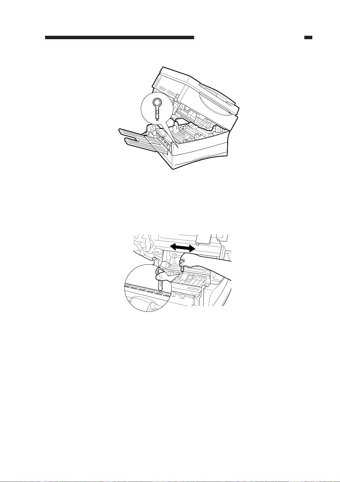
a. Static Eliminator
1) Remove the static eliminator cleaner from the machine.
Figure 1-503 (Copyboard type)
1-18
COPYRIGHT © 1999 CANON INC. CANON PC800s/900s REV.0 AUG. 1999 PRINTED IN JAPAN (IMPRIME AU JAPON)
Page 31
CHAPTER 1 GENERAL DESCRIPTION
Figure 1-504 (ADF type)
2) Pull the open/close lever to open the machine.
3) Using the static eliminator cleaner, clean the static eliminator.
• Brush out the paper lint or the like from the groove of the static eliminator.
Figure 1-505
4) Close the machine as soon as you have finished cleaning. (Work briskly.)
COPYRIGHT © 1999 CANON INC. CANON PC800s/900s REV.0 AUG. 1999 PRINTED IN JAPAN (IMPRIME AU JAPON)
1-19
Page 32
CHAPTER 1 GENERAL DESCRIPTION
VI. IMAGE FORMATION
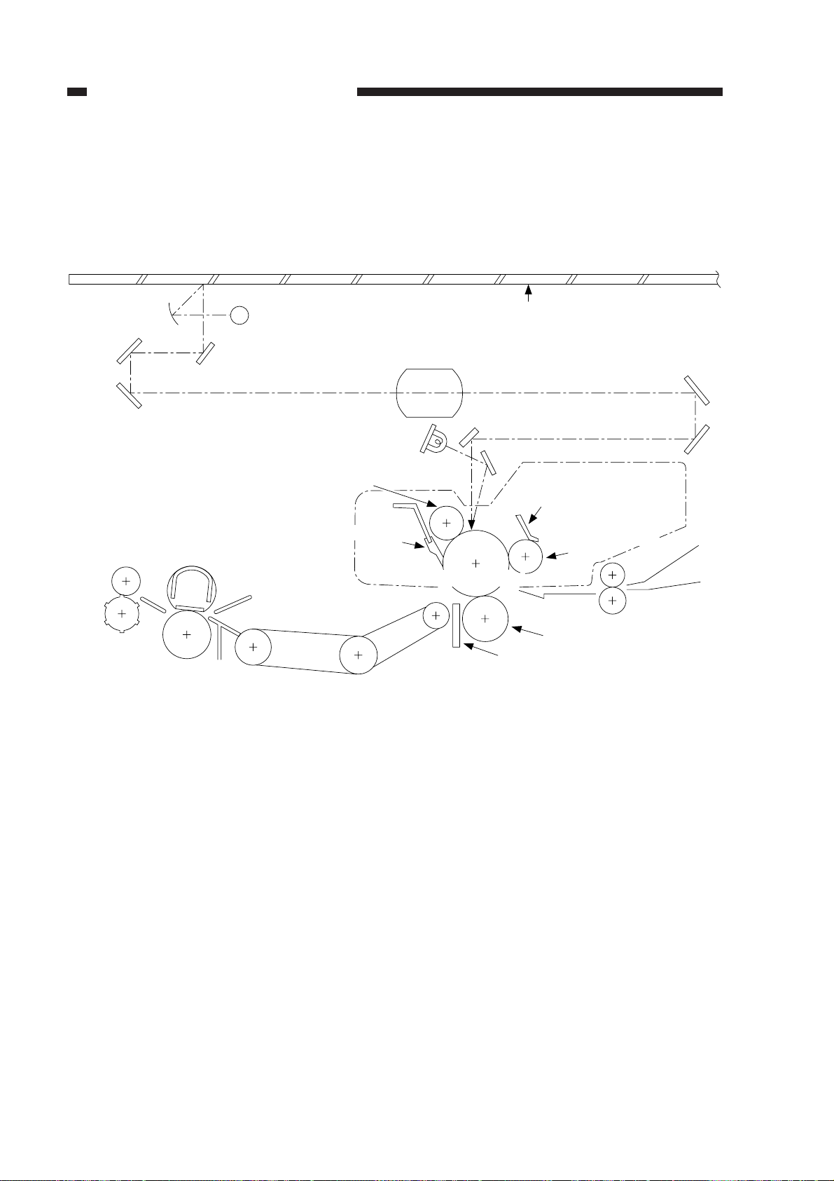
A. Outline
The construction of the machine is as follows:
Primary charging roller
Fixing assembly
Scanning lamp
Side blanking lamp
(front, rear)
Cleaning blade
Copyboard glass
Fixed focal point lens
Developing blade
Developing cylinder
Photosensitive drum
Transfer charging roller
Static eliminator
Figure 1-601
1-20
COPYRIGHT © 1999 CANON INC. CANON PC800s/900s REV.0 AUG. 1999 PRINTED IN JAPAN (IMPRIME AU JAPON)
Page 33
CHAPTER 1 GENERAL DESCRIPTION
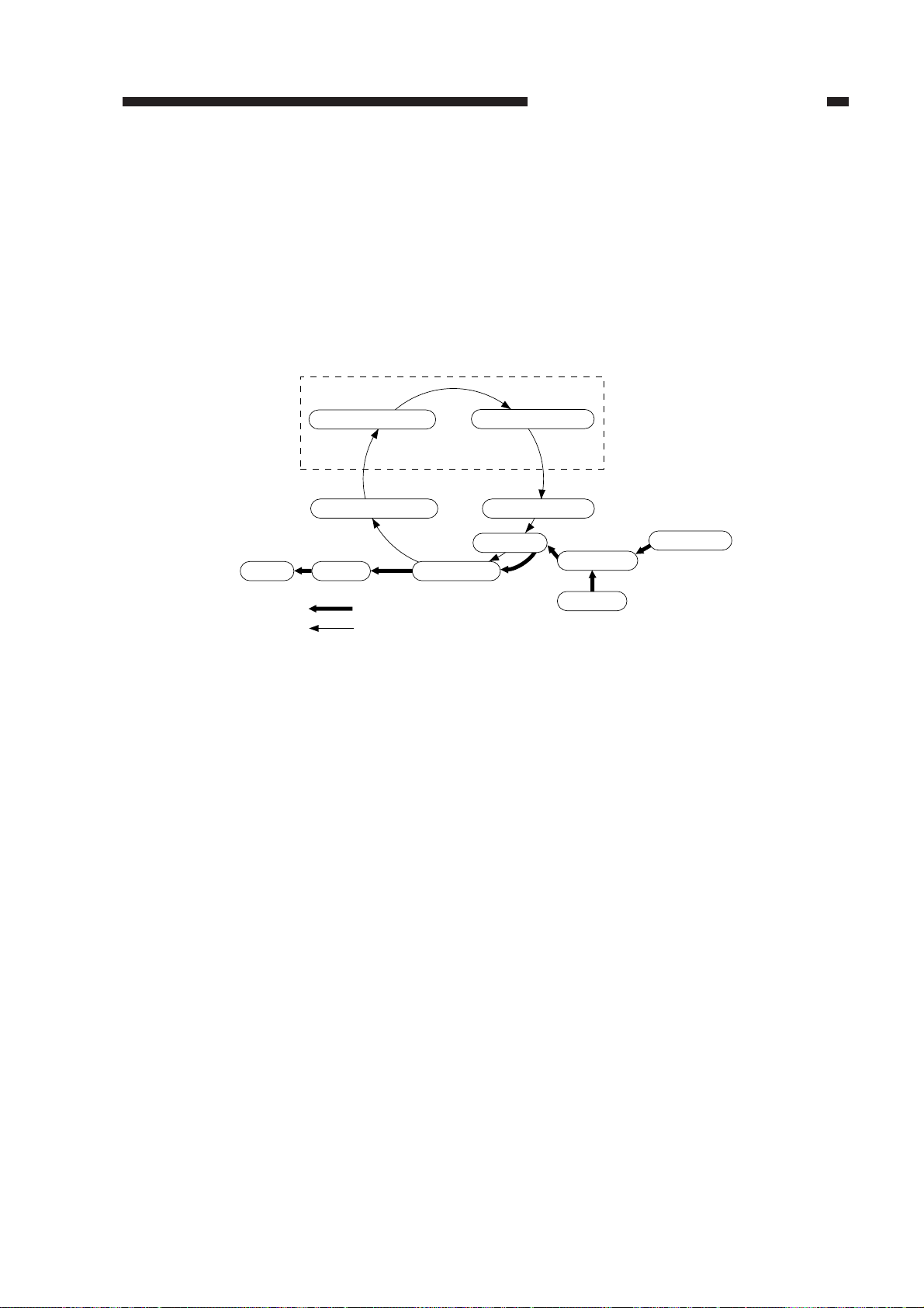
The machine’s image formation process consists of the following seven steps:
Step 1 Primary charging (AC + negative DC)
Step 2 Image exposure
Step 3 Development (AC + negative DC)
Step 4 Transfer (negative DC)
Step 5 Separation (curvature separation + static eliminator; positive DC)
Step 6 Fixing
Step 7 Drum cleaning
Static latent image formation block
Delivery
1. Primary charging
7. Drum cleaning
6. Fixing
: Flow of copy paper
: Rotation of the photosensitive drum
5. Separation
2. Image exposure
3. Development
4. Transfer
Figure 1-602
Manual feed
Registration
Cassette
COPYRIGHT © 1999 CANON INC. CANON PC800s/900s REV.0 AUG. 1999 PRINTED IN JAPAN (IMPRIME AU JAPON)
1-21
Page 34

Page 35

CHAPTER 2
BASIC OPERATION
This chapter provides descriptions on basic operations, functions of each operation,
relationships between electrical and mechanical systems, and timing at which each
associated part is turned on.
Process speed 96 mm/sec
I. BASIC OPERATIONS .................. 2-1
A. Functional Constr uction ........2-1
B. Outline of Electr ical
Circuitry .................................2-2
C. Basic Sequence of
Operations.............................2-3
COPYRIGHT © 1999 CANON INC. CANON PC800s/900s REV.0 AU G. 1999 PRINTED IN JAPAN (IMPRIME AU JAPON)
D. Controlling the Main Motor
(M1) .......................................2-5
E. Inputs to and Outputs from
the DC Controller ..................2-7
Page 36

Page 37
CHAPTER 2 BASIC OPERATION
I. BASIC OPERATIONS
A. Functional Construction
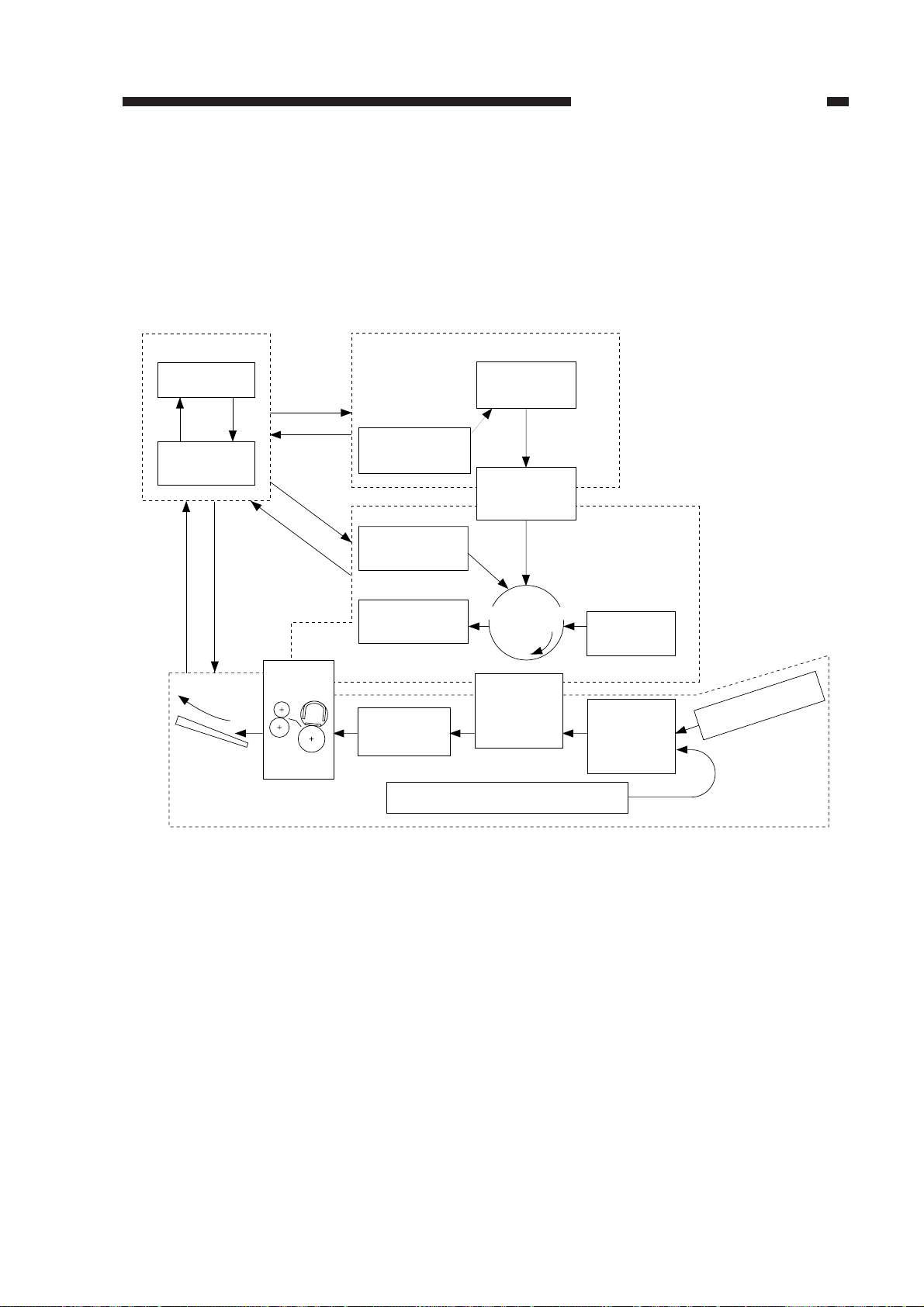
The machine consists of four functional blocks: pickup/feeding system, exposure system, im-
age formation system, and control system.
Control system
Control panel
Control circuit
Copy tray
Fixing assembly/
delivery assembly
Exposure system
Original
illuminating block
Primary charging
roller
Drum
cleaning block
Feeding
Copyboard
Optical block
Photosensitive
drum
Transfer/
separation
Cassette
Image formation
system
Developing
assembly
Pickup
control block
Manual feed block
Pickup/
feeding system
Figure 2-101
COPYRIGHT © 1999 CANON INC. CANON PC800s/900s REV.0 AUG. 1999 PRINTED IN JAPAN (IMPRIME AU JAPON)
2-1
Page 38
CHAPTER 2 BASIC OPERATION
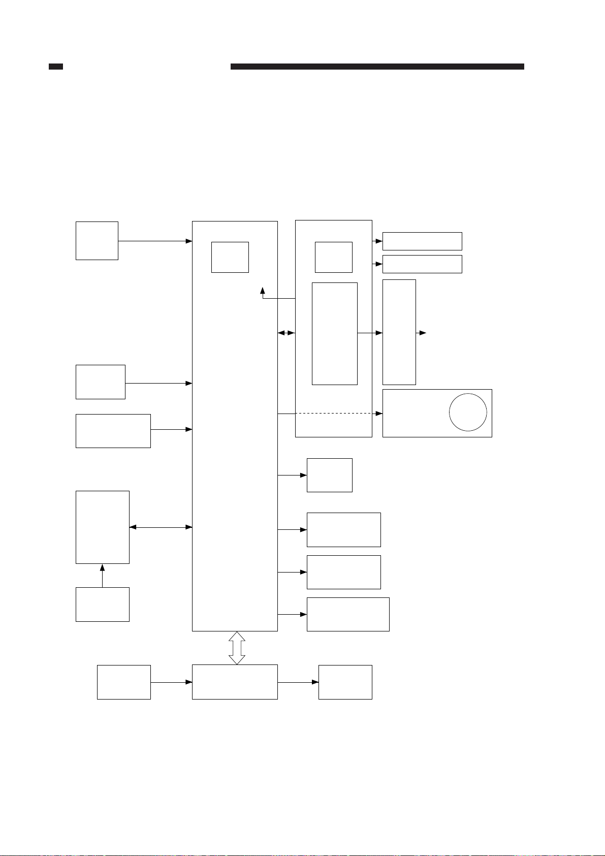
B. Outline of Electrical Circuitry
The machine’s major electric mechanisms are controlled by the microprocessor mounted on
the DC controller PCB, which reads input signals from sensors and operating keys according to the
instructions of the program stored in advance and sends signals used to drive motors, solenoids,
lamps, and other loads as needed.
<Loads><Sensor Block> <Control Block>
Composite
power supply PCB
Q900
CPU
High-
voltage
circuit
block
Scanning lamp
Fixing heater
Contact
PCB
• Primary charging roller
• Developing cylinder
• Transfer charging roller
• Static eliminator
Sensor
• Scanner home position detection
• Lens home position detection
• Pre-registration roller paper
detection
• Delivery paper detection
• Vertical path roller paper detection
• Single-feeder paper detection
DC controller PCB
Q101
CPU
+5V
+24V
AE sensor
PCB
Thermistor
• Scanner thermistor
• Fixing thermistor
Control
panel
Power
switch
• Pickup clutch solenoid
• Registration clutch solenoid
Solenoid
Side blanking
Scanner/
lens drive motor
Scanner cooling fan
• Lens solenoid
• Multifeeder pickup solenoid
• Cassette pickup solenoid
lamp
Main motor
driver PCB
Main
motor
2-2
Sensor/
switch
ADF
ADF load
Figure 2-102
COPYRIGHT © 1999 CANON INC. CANON PC800s/900s REV.0 AUG. 1999 PRINTED IN JAPAN (IMPRIME AU JAPON)
Page 39
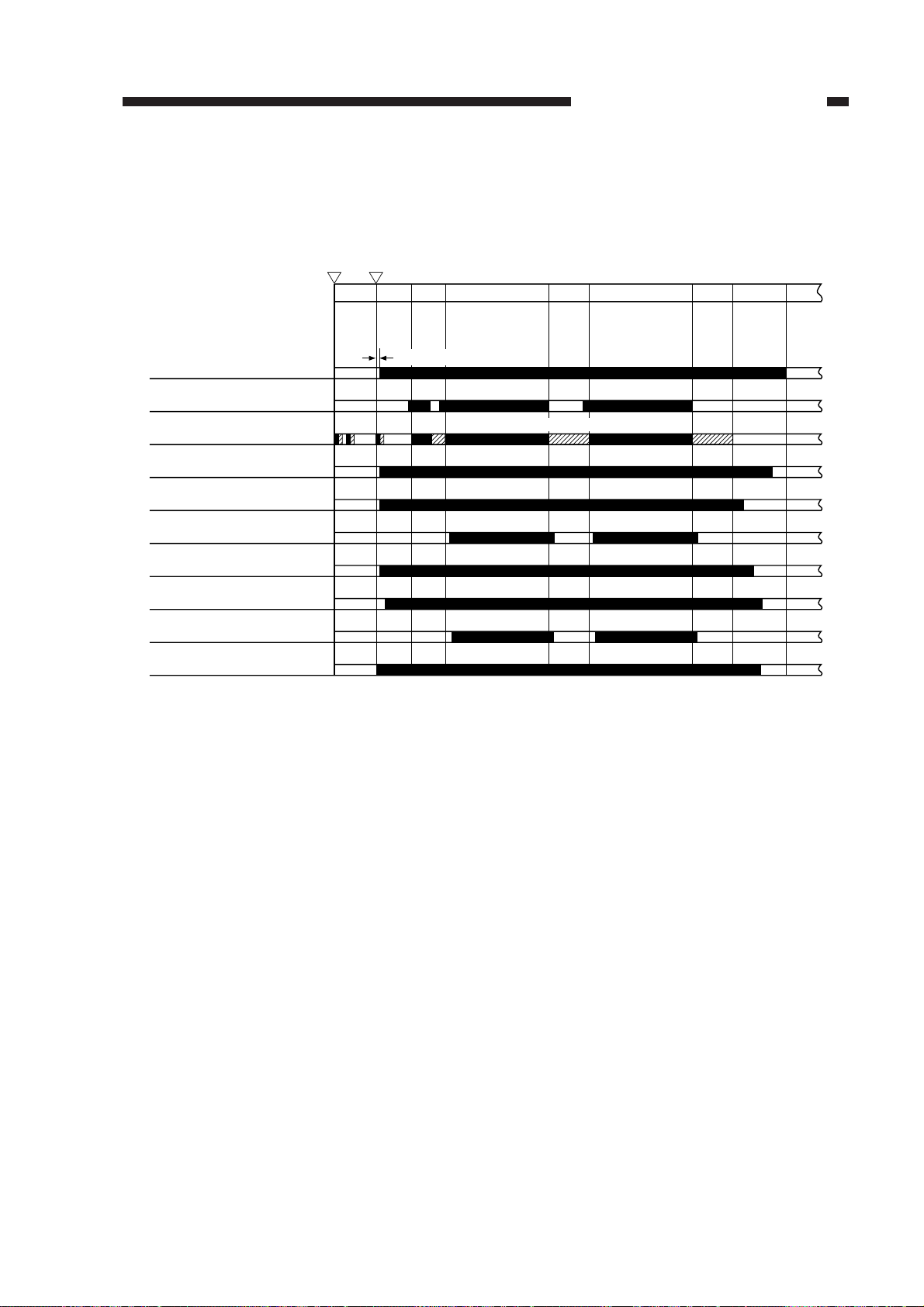
C. Basic Sequence of Operations
• A4R, Direct, 2 Copies, Continuous, Cassette
Copy Start keyPower switch
ONON
CHAPTER 2 BASIC OPERATION
STBY INTR AER
Main motor (M1)
Scanning lamp (LA1)
Scanner
Primary AC bias
Primary DC bias
Developing AC bias
Developing DC bias
Transfer bias
Static eliminator bias
Fixing heater (H1)
III I
0.3sec (approx.)
I : Scanner home position detection
II : Lens home position detection
SCFW
Forward
SCRV
Reverse
SCFW
SCRV
LSTR
STBY
Figure 2-103
COPYRIGHT © 1999 CANON INC. CANON PC800s/900s REV.0 AUG. 1999 PRINTED IN JAPAN (IMPRIME AU JAPON)
2-3
Page 40

CHAPTER 2 BASIC OPERATION
STBY
(standby)
INTR
(initial rotation)
AER
(AE rotation)
SCFW
(scanner forward)
SCRV
(scanner reverse)
LSTR
(last rotation)
Period
• From when he power switch is turned
on to when the Copy Start key is
pressed.
• From when LSTR ends to when the
Copy Start key is pressed.
From when the Copy Start key is
pressed to when the scanner moves forward.
While the scanner moves forward about
10 cm and then moves it in reverse.
While the scanner is moving forward.
• The distance varies according to the
selected copy size and reproduction
ratio.
• The forward speed varies according to
the selected reproduction ratio.
While the scanner is moving in reverse.
• The reverse speed is about 3.3 as fast
as the forward speed used in Direct.
From when SCRV ends to when the
main motor stops.
Description
Waits until the Copy Start key is
pressed.
Removes residual charges from the
photosensitive drum, thereby ensuring
a stable drum sensitivity.
Measures the density of the original.
Illuminates the original by the scanning
lamp, and the reflected optical image is
projected to the photosensitive drum
through mirrors and lenses.
Moves the scanner to the home position
in preparation for the next copying run.
Neutralizes the drum surface potential
as post-processing.
Table 2-101
2-4
COPYRIGHT © 1999 CANON INC. CANON PC800s/900s REV.0 AUG. 1999 PRINTED IN JAPAN (IMPRIME AU JAPON)
Page 41
CHAPTER 2 BASIC OPERATION
D. Controlling the Main Motor (M1)
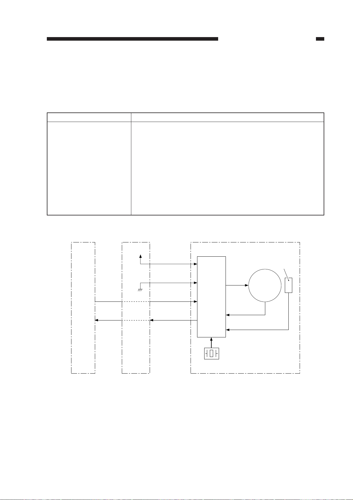
1. Outline
Table 2-102 shows the functions of the main motor control circuit, and Figure 2-104 is a block
diagram of the circuit.
Item
Power supply
Drive signal
Moving/drive parts
Control
Error detection
DC
controller
PCB
J103
-6
J203
-3
Description
24 VDC from the composite power supply.
Signal (MMD) from the DC controller PCB.
Photosensitive drum, primary charging roller, developing assembly,
transfer charging roller, pickup roller, vertical roller, registration roller,
feeding assembly, fixing assembly, delivery roller, heat exhaust fan
Executes on/off control.
Executes constant speed rotation control.
Issues ‘E010’.
Table 2-102
+24V
J205
-4
-3
-2
24V
GND
MMD
J901
-1
-2
-3
Phase
control
drive
circuit
Drive
current
Clock pulse
generator
Main motor
(M1)
J104-1J204
-7
Composite
power
supply
PCB
-1
MLOCK
-4
Reference signal
Hall IC output
MMCLK
Main motor drive PCB
Figure 2-104
COPYRIGHT © 1999 CANON INC. CANON PC800s/900s REV.0 AUG. 1999 PRINTED IN JAPAN (IMPRIME AU JAPON)
2-5
Page 42

CHAPTER 2 BASIC OPERATION
2. Operations
The main motor (M1) is a DC motor with a built-in clock pulse generator, which generates
clock pulses (MMCLK) in relation to the rotation of the motor while the motor is rotating.
The speed control circuit controls the main motor (M1) so that it rotates at a specific speed by
matching the frequency of these clock pulses and that of the reference signals.
When the main motor drive signal (MMD) from the DC controller circuit goes ‘1’, the motor
diver drive circuit turns on, causing the main motor (M1) to rotate at a specific speed.
While the main motor is rotating at a specific speed, the main motor driver PCB keeps sending
the constant speed state signal (MLOCK=0) to the DC controller PCB. If the rotation of the motor
starts to have fluctuations, the MLOCK signal goes ‘1’.
Related Error Code
E010
While the main motor drive signal is generated, the rotation of the main motor deviates from
a specific number for 1 sec or more.
a. Turning On/Off the Main Motor
When the main motor drive signal (MMD) from the DC controller circuit goes ‘1’, the main motor
driver turns on to rotate the main motor (M1).
b. Rotating the Main Motor at a Constant Speed
The drive circuit on the motor driver PCB controls the main motor so that the phase of the frequency of the clock pulse signals (MMCLK) occurring when the motor rotates and that of the
frequency of the reference signals match. The main motor driver PCB sends the constant speed
state signal (MLOCK=0) to the DC controller circuit.
c. Detecting an Error (E010)
If the rotation of the main motor starts to have fluctuations for some reason, the MLOCK signal
goes ‘1’. If the signal remains ‘1’ for about 1 sec, the DC controller will find the condition to be a
fault in the main motor, and will stop the main motor and, at the same time, indicate ‘E010’ in the
display.
2-6
COPYRIGHT © 1999 CANON INC. CANON PC800s/900s REV.0 AUG. 1999 PRINTED IN JAPAN (IMPRIME AU JAPON)
Page 43
CHAPTER 2 BASIC OPERATION
PS1
PS2
PS3
TH1
TH2
J101-1
-3
-2
J109-11
-10
-9
J102-7
-9
-8
J132-3
-5
-4
J108-4
-3
-5
J102-1
-6
J131-1
-2
SCHP
LHP
DPD
DIG3
PDP
+5V
+5V
+5V
RPD
+5V
TH1
TH2
DC controller PCB
When the scanner is in the home position, ‘1’.
(The light-blocking plate is at PS1, ‘1’.)
When the lens is in the home position, ‘1’.
(The light-blocking plate is at PS2, ‘1’.)
When PS3 has detected paper, ‘0’.
(The light-blocking plate is at PS3, ‘1’.)
When PS4 has detected paper, ‘1’.
(The light-blocking plate is at PS4, ‘1’.)
When Q751 has detected paper, ‘1’.
(The light-blocking plate is at PS751, ‘0’.)
When the surface temperature of the fixing
heater increases, the voltage decreases.
(analog signal)
When the temperature of the scanner increases,
the voltage decreases. (analog signal)
Scanner home
position sensor
Lens home
position sensor
Delivery sensor
Vertical path roller
paper sensor
Pre-registration
roller paper sensor
Fixing thermistor
Scanner thermistor
PS4
J113-1
-3
-2
SFPD
DIG2
When PS5 has detected paper, ‘0’.
(The light-blocking plate is at PS5, ‘1’.)
Single-feeder
paper sensor
(Single-feeder type only)
PS5
J62
J62J433
Q751
Sensor PCB
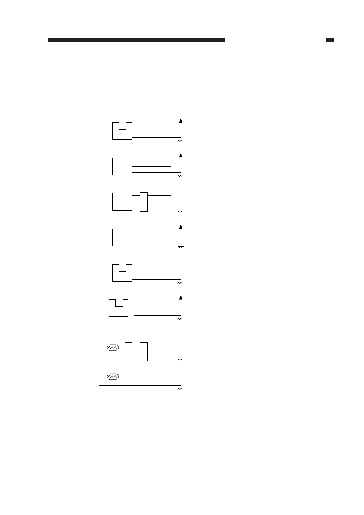
E. Inputs to and Outputs from the DC Controller
1. Inputs to the DC Control (1/2)
Figure 2-105
COPYRIGHT © 1999 CANON INC. CANON PC800s/900s REV.0 AUG. 1999 PRINTED IN JAPAN (IMPRIME AU JAPON)
2-7
Page 44
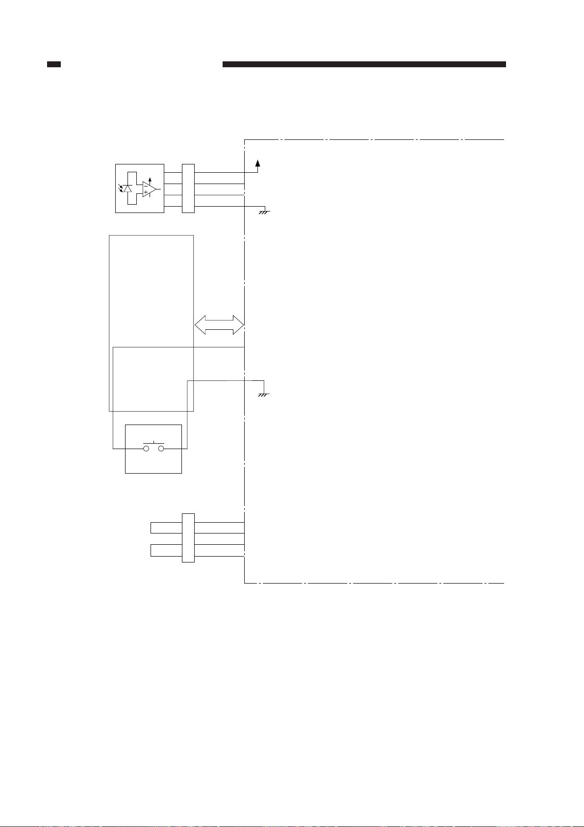
CHAPTER 2 BASIC OPERATION
2. Inputs to the DC Controller (2/2)
DC controller PCB
AE sensor PCB
Control panel
PCB
+24V
SW309
J601
J107-4
J111J301
J111-15
J111-16
-3
-2
-1
+24V
AE
AEREF
PWOFF
When the light reflected by the original increases,
the voltage increases.
The keys and the LEDs are wired in a matrix
in the control panel PCB, and the DC controller
turns on or flashes the LEDs and reads key inputs.
2-8
J62
J102-2
-3
-4
-5
DIG1
HEAT0
DIG1
HEAT1
The variation in the resistance of the fixing heater
is corrected in three levels based on combinations
of 2-bit signals.
Figure 2-106
COPYRIGHT © 1999 CANON INC. CANON PC800s/900s REV.0 AUG. 1999 PRINTED IN JAPAN (IMPRIME AU JAPON)
Page 45
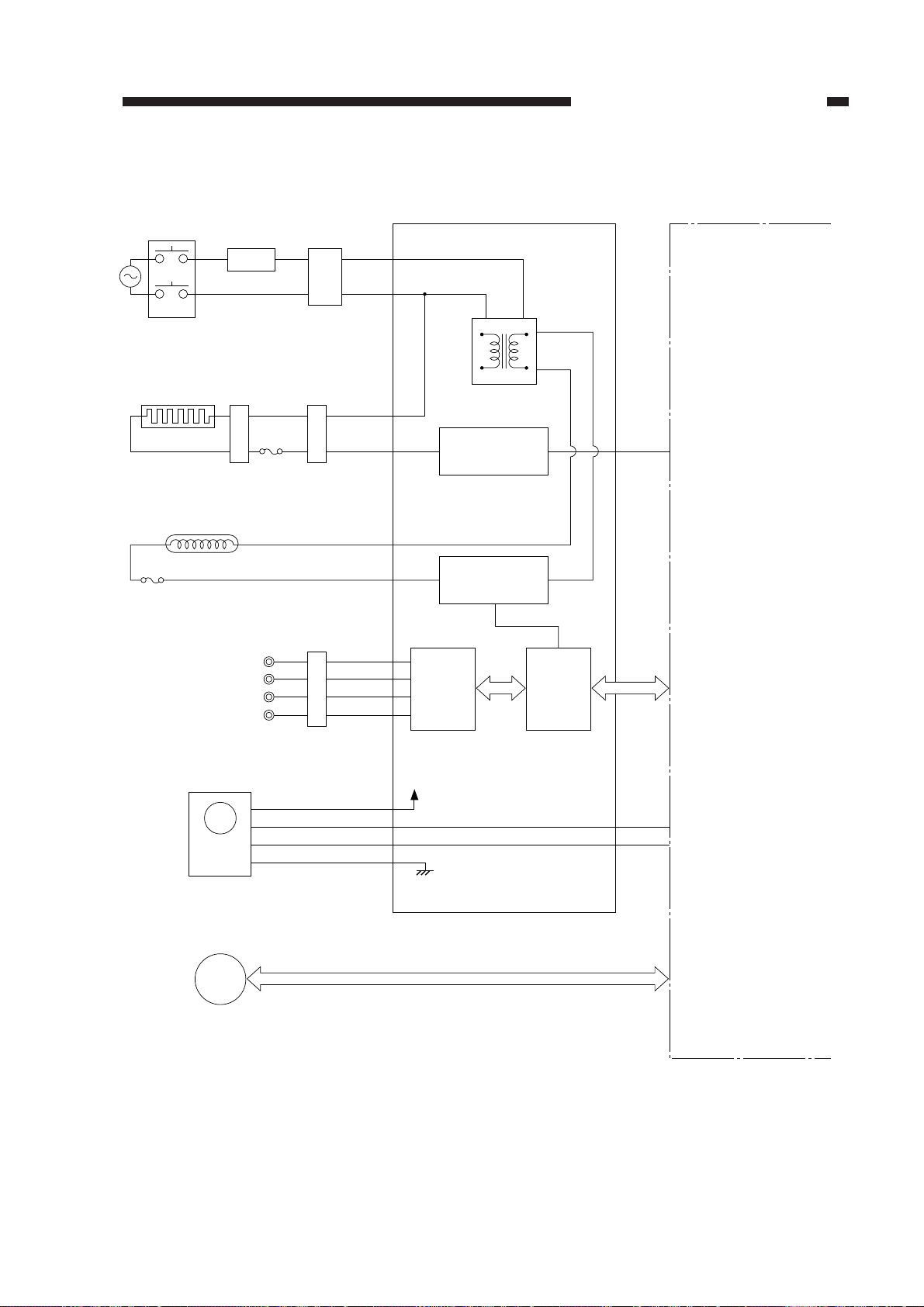
3. Outputs from the DC Controller (1/2)
DS1
Door switch
Line filter
LF1
(220/240V model only)
Noise filter
NF1
J201-2
-1
CHAPTER 2 BASIC OPERATION
DC controller PCBComposite power supply PCB
Fixing heater
H1
Thermal fuse 2
Scanning lamp
FU1
Thermal fuse 1
Primary charging roller
Developing cylinder
Transfer charging roller
Static eliminator
LA1
M1
Main
motor
FU2
HVT board
J434J16
J207-1
-2
J910-3
-1
voltage
+24V
Transformer
Fixing heater
activation circuit
Scanning lamp
activation circuit
High-
circuit
block
Micro-
processor
J104-2
J103-6
J104-1
HEAT_TRG
Communication with
the composite power
supply
MMD
MLOCK
When ‘0’,
the fixing heater
turns on.
See p. 2-5.
Main motor
driver PCB
M2
Scanner/
lens drive motor
See p. 3-7.
Figure 2-107
COPYRIGHT © 1999 CANON INC. CANON PC800s/900s REV.0 AUG. 1999 PRINTED IN JAPAN (IMPRIME AU JAPON)
2-9
Page 46
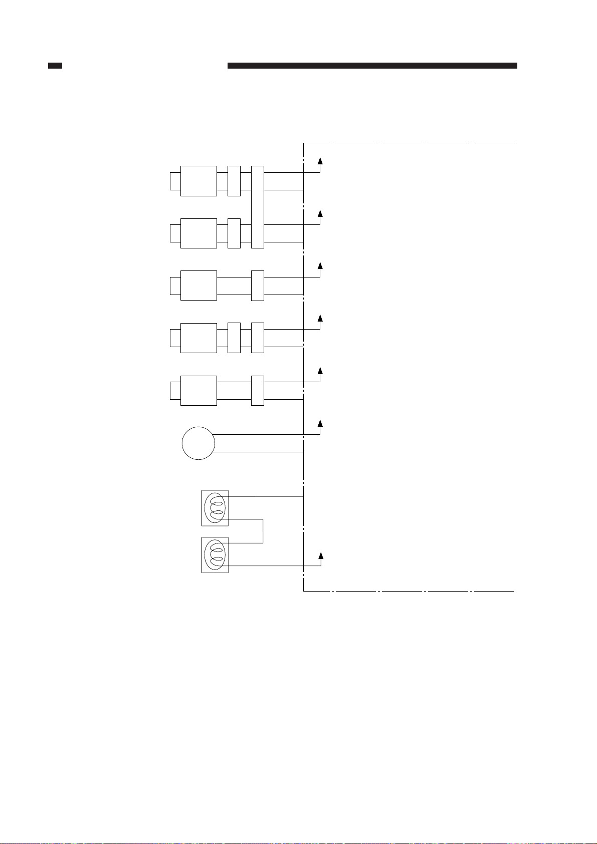
CHAPTER 2 BASIC OPERATION
4. Outputs from the DC Control PCB (2/2)
DC controller PCB
Pickup clutch solenoid
Registration clutch solenoid
Lens solenoid
Multifeeder pickup solenoid
(Multifeeder type only)
Cassette pickup solenoid
Scanner cooling fan
SL1
SL2
SL3
SL4
SL5
FM1
J53
J54
J55
J51
J52
J51
J58
J109-4
J109-6
J109-2
J109-8
J132-2
J130-1
-3
-5
-1
-7
-1
-2
+24V
PUSLD*
+24V
RGSLD*
+24V
LNSLD*
+24V
MFSLD*
+24V
CPUSD*
+24V
FM1D*
When ‘0’, the pickup clutch solenoid
turns on.
When ‘0’, the registration clutch
solenoid turns on.
When ‘0’, the lens solenoid turns on.
When ‘0’, the multifeeder pickup
solenoid turns on.
When ‘0’, the cassette pickup solenoid
turns on.
When ‘0’, the scanner cooling fan
turns on.
Side blanking lamp (rear)
Side blanking lamp (front)
J106-1
SB_LP*
+24V
-2
Figure 2-108
When ‘0’, the blanking lamp turns on.
2-10
COPYRIGHT © 1999 CANON INC. CANON PC800s/900s REV.0 AUG. 1999 PRINTED IN JAPAN (IMPRIME AU JAPON)
Page 47
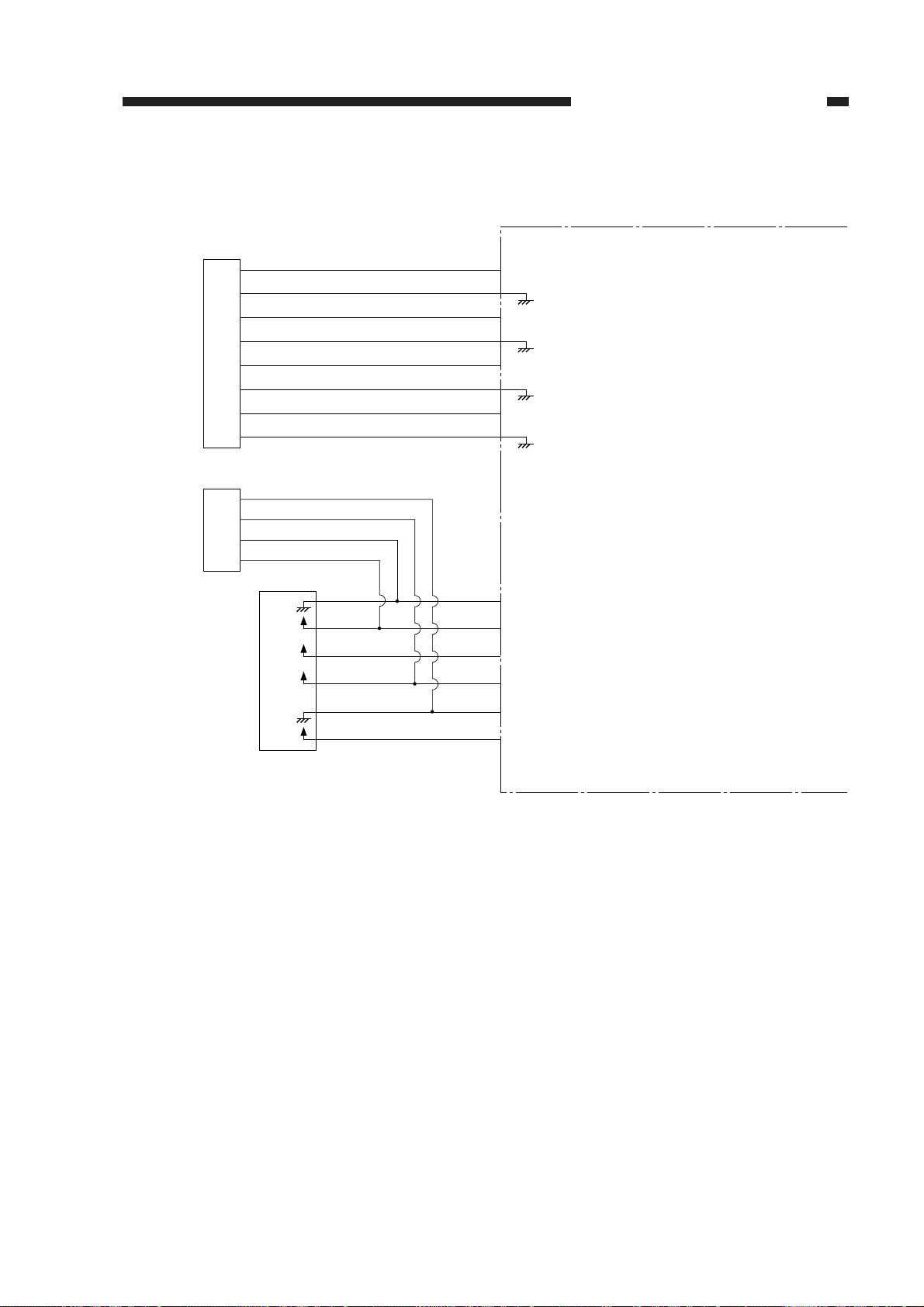
5. Inputs to and Outputs from the ADF
Composite power supply PCB
+24V
+5V
+5V
+24V
J114-1
-2
REQ
-3
-4
ACK
-5
-6
TXD
-7
-8
-8
-7
-6
-5
-4
-3
-2
-1
RXD
DC controller PCB
See Chapter 8.
To the ADF
-4
-3
-2
-1
To the ADF
J60
J105-6
-5
-4
-3
-2
-1
J202-1
-2
-3
-4
-5
-6
J24
CHAPTER 2 BASIC OPERATION
Figure 2-109
COPYRIGHT © 1999 CANON INC. CANON PC800s/900s REV.0 AUG. 1999 PRINTED IN JAPAN (IMPRIME AU JAPON)
2-11
Page 48

Page 49

CHAPTER 3
EXPOSURE SYSTEM
This chapter discusses the principles of operation used for the machine's lens drive
unit and scanner drive unit. It also explains the timing at which these drive units are
operated, and shows how they may be disassembled/assmbled and adjusted.
I. OPERATIONS ..............................3-1
A. Outline ...................................3-1
B. Varying the Reproduction
Ratio......................................3-2
C. Lens Drive System ................3-3
D. Scanner Drive System ..........3-4
II. EXPOSURE SYSTEM .................3-9
COPYRIGHT © 1999 CANON INC. CANON PC800s/900s REV.0 AU G. 1999 PRINTED IN JAPAN (IMPRIME AU JAPON)
A. Controlling the Scanning
Lamp .....................................3-9
III. DISASSEMBLY/ASSEMBLY ..... 3-12
A. Scanner Dr ive Assembly.... 3-13
B. Lens Dr ive Assembly ......... 3-31
C. Exposure System ............... 3-37
Page 50

Page 51
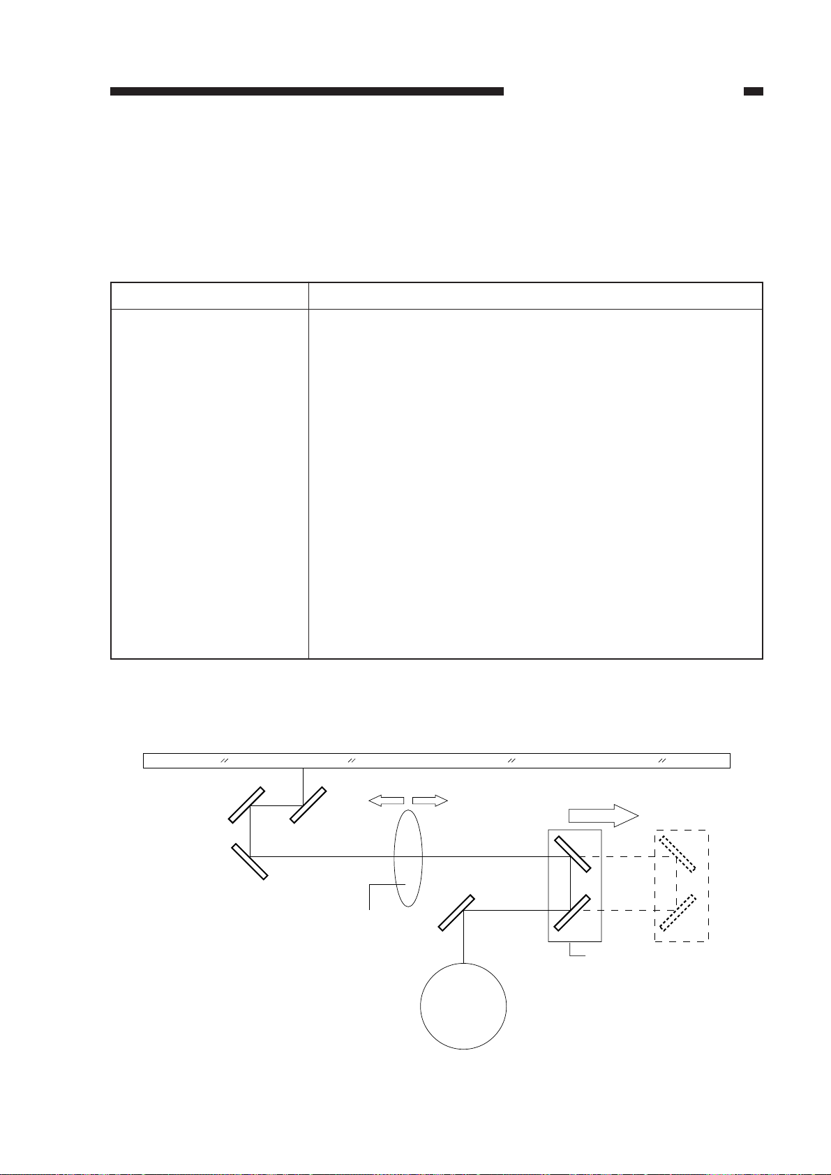
I. OPERATIONS
A. Outline
Table 3-101 shows the major functions of the exposure system.
CHAPTER 3 EXPOSURE SYSTEM
Item
Lamp
Scanning
Scanner position detection
Ratio variation
Lens drive control
Scanner drive control
Protective function
Description
Halogen
By moving the No. 1 mirror mount
By a sensor (scanner home position sensor; PS1)
Main scanning direction:by varying the optical length
Sub scanning direction:by varying the speed of the No. 1 mirror mount
Scanner/lens drive motor (M2)
Fixed focal point lens unit
Mobile No. 4/5 mirror unit
Scanner/lens drive motor (M2)
Scanner thermistor (TH2)
By a fuse (blows in response to overheating of the scanning lamp to cut
power to the lamp)
• Thermal fuse (FU1; blows at 128°C)
Table 3-101
Copyboard glass
Enlarge Reduce
Fixed focal point lens
Photosensitive
drum
Moves for enlargement/
reduction
No. 4/5 mirror unit
Figure 3-101
COPYRIGHT © 1999 CANON INC. CANON PC800s/900s REV.0 AUG. 1999 PRINTED IN JAPAN (IMPRIME AU JAPON)
3-1
Page 52
CHAPTER 3 EXPOSURE SYSTEM
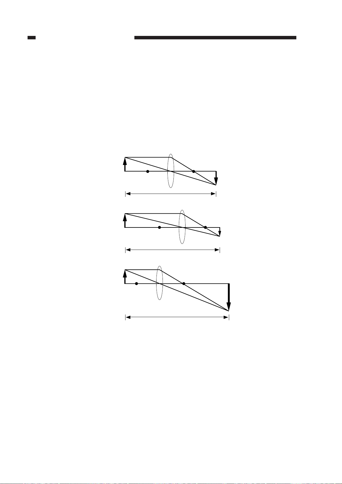
B. Varying the Reproduction Ratio
The reproduction ratio in the drum axial direction (main scanning direction) is varied by the
lens drive system, and that in the drum peripheral direction (sub scanning direction) is changed by
the scanner drive system.
In the lens drive system, the positions of the fixed focal point lens and the No. 4/5 mirror are
changed to vary the reproduction ratio.
In the scanner system, the relative speed of the No. 1 mirror mount is made higher (for reduction) or lower (for enlargement) than the drum peripheral speed.
F'
Direct
F
Optical length
Reduction
F
Optical length
Enlargement
F
Optical length
Optical length: L1 < L2, L1 < L3
Figure 3-102
L1
F'
L2
F'
L3
3-2
COPYRIGHT © 1999 CANON INC. CANON PC800s/900s REV.0 AUG. 1999 PRINTED IN JAPAN (IMPRIME AU JAPON)
Page 53
CHAPTER 3 EXPOSURE SYSTEM
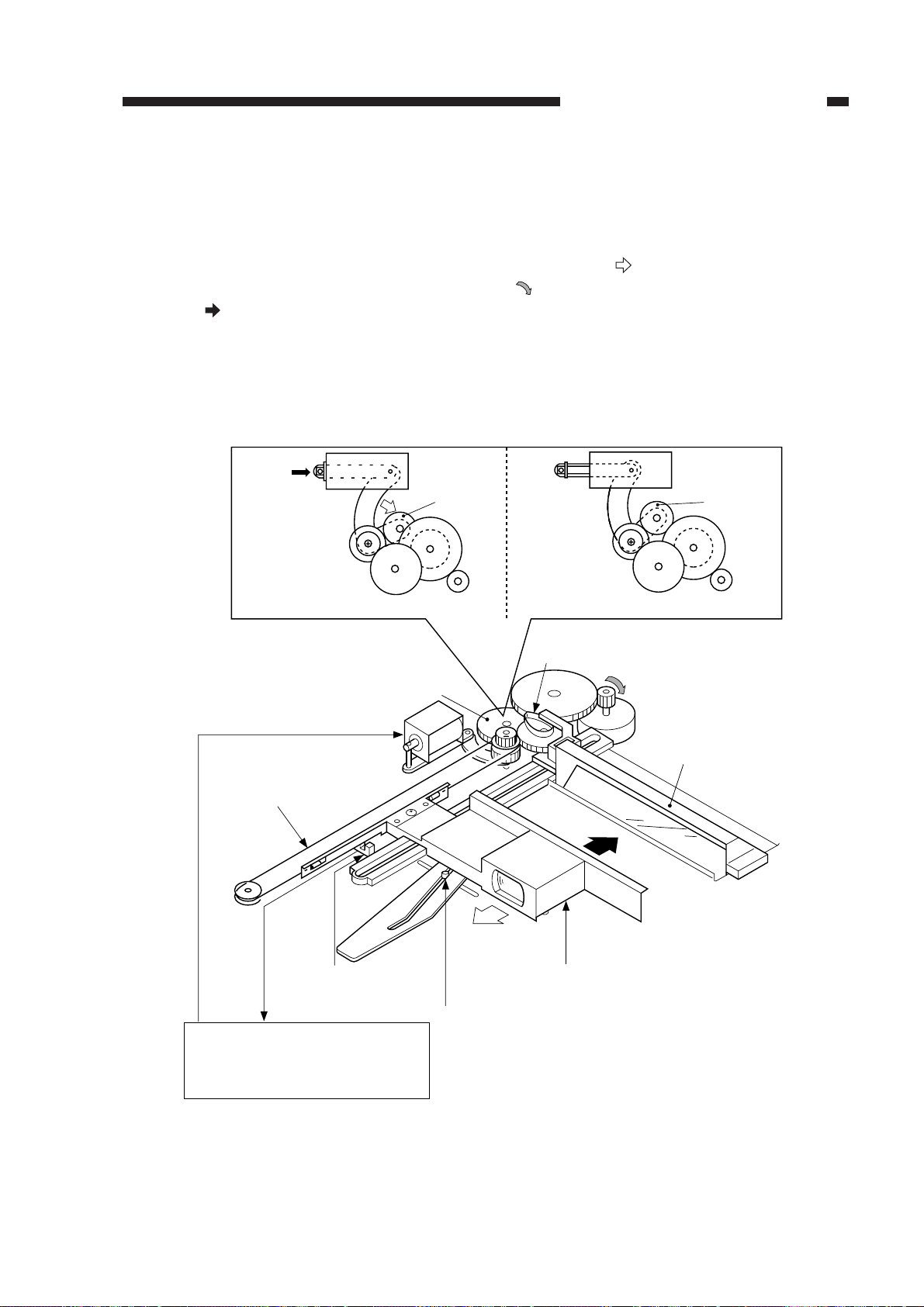
C. Lens Drive System
1. Outline
The lens drive system is driven by the scanner/lens drive motor (M2). When the lens solenoid
(SL3) turns on, the switching gear is pushed in the direction of
scanner/lens drive motor rotates in reverse direction (
reduction (
) by the work of the gear and the lens cable.
), the lens unit will move in the direction of
At the same time, the No. 4/5 mirror unit operates according to the distance over which the lens
unit is moved by the work of the gear and the cam, thereby varying the optical length.
At this time, the blanking lamp also moves in conjunction with the lens to blank out the appropriate front/rear widths to suit the selected reduction ratio.
SL3 SL3
ON OFF
Switching
gear
. In this condition, when the
Switching
gear
While the lens is moving
Switching gear
Lens cable
Lens home position
Lens home position detection
Lens solenoid drive signal(LNSLD*)
signal(LHP)
DC controller PCB
sensor (PS2)
Top View
Cam
SL3
Enlargement
Lens unit
Lens shift detecting shaft
for side blanking lamp
While the scanner is moving
Scanner/lens drive motor
(M2)
No. 4/5 mirror unit
Reduction
Figure 3-103
COPYRIGHT © 1999 CANON INC. CANON PC800s/900s REV.0 AUG. 1999 PRINTED IN JAPAN (IMPRIME AU JAPON)
3-3
Page 54
CHAPTER 3 EXPOSURE SYSTEM
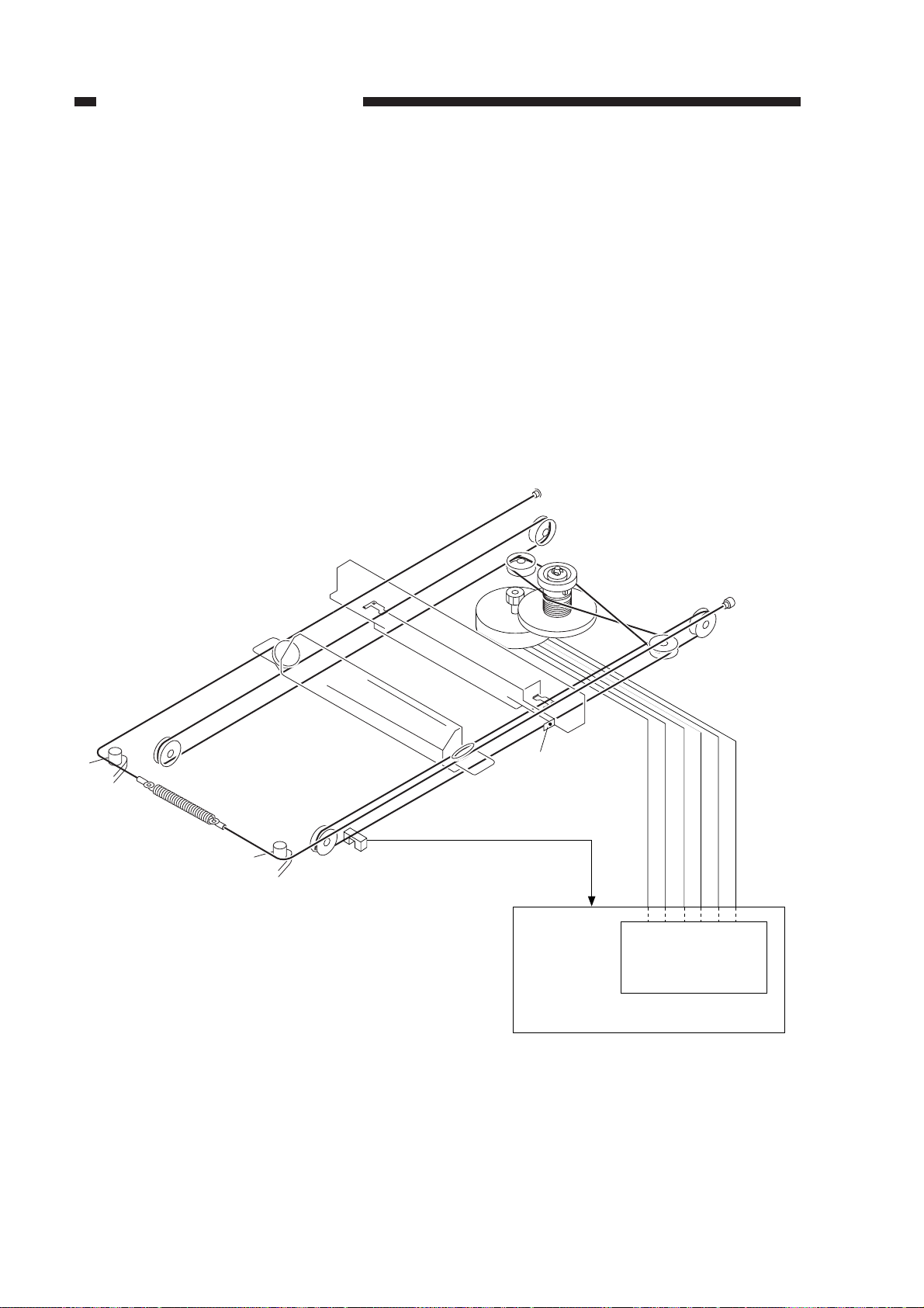
D. Scanner Drive System
1. Outline
The scanner is driven by the scanner/lens drive motor (M2), whose direction of rotation
changes to move the scanner forward or in reverse.
When moving the scanner forward, the speed of rotation of the motor varies according to the
selected reproduction ratio on a continuous basis; when moving the scanner in reverse, on the other
hand, its speed remains the same regardless of the selected reproduction ratio in normal copying
(312mm/sec, about 3.3 as fast as when moving the scanner forward in Direct).
The distance over which the scanner is moved varies according to the length of copy paper and
the selected reproduction ratio.
The scanner/lens drive motor dives the lens drive system as well as the scanner.
M2
PS1 Light-blocking
plate
Scanner home position signal (SCHP)
Scanner home position sensor (PS1)
J101-1
-2 SC_B*
-4 SC_COM
-5 SC_A*
-6 SC_A
J110-1 SC_COM
-3 SC_B
Q109
Motor driver circuit
DC controller PCB
3-4
Figure 3-104
COPYRIGHT © 1999 CANON INC. CANON PC800s/900s REV.0 AUG. 1999 PRINTED IN JAPAN (IMPRIME AU JAPON)
Page 55
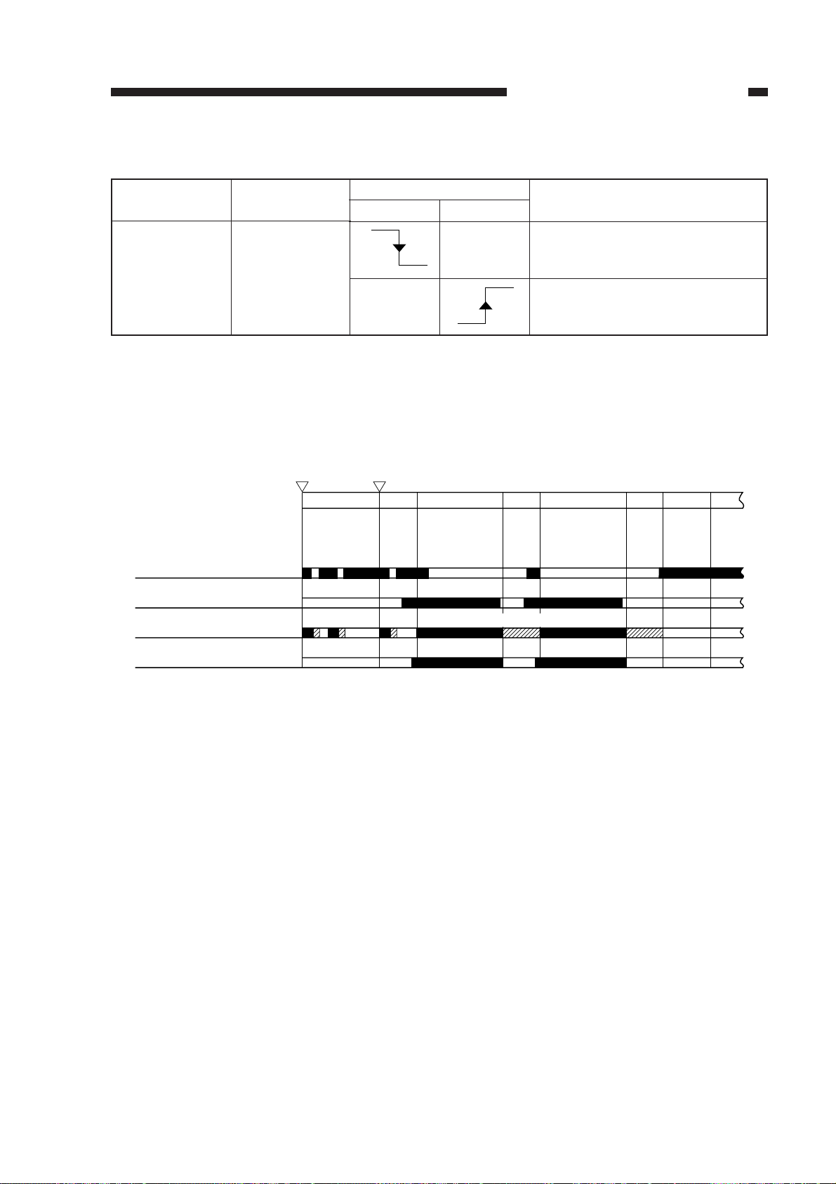
CHAPTER 3 EXPOSURE SYSTEM
2. Relationship between Scanner Sensor and Signal
Scanner sensor
Signal
Forward Reverse
PS1(scanner
home position
Scanner
sensor)
SCHP
Table 3-102
3. Basic Sequence of Operations (scanner)
Power switch
Scanner home position
sensor (PS1)
Pre-registration roller
paper sensor (Q751)
Scanner
Copy Start key
STBY
III
ONON
INTR
I
SCFW
Forward
Description
• Provides a means of reference for
determining forward movement
distance.
• Stops the scanner moving in reverse in 0.1 sec.
SCRV
Reverse
SCFW
SCRV
LSTR
STBY
Scanning lamp(LA1)
I : Scanner home position detection
II : Lens home position detection
Figure 3-105
The microprocessor on the DC controller PCB controls the forward movement distance of the
scanner with reference to the falling edge of the scanner home position signal. The forward movement distance of the scanner varies according to the length of copy paper and reproduction ratio. If
the ratio is less than 130%, the scanner is moved forward as if for A4 (297 mm); if it is 130% or
more, the scanner is moved forward as if for LTR (279 mm).
For descriptions on how length is detected, see p. 5-10.
COPYRIGHT © 1999 CANON INC. CANON PC800s/900s REV.0 AUG. 1999 PRINTED IN JAPAN (IMPRIME AU JAPON)
3-5
Page 56
CHAPTER 3 EXPOSURE SYSTEM
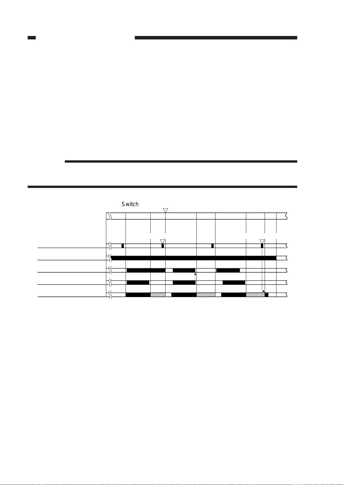
4. Controlling the Copying Speed
The machine uses a halogen lamp for scanning, and the heat of the lamp increases the tempera-
ture of the copyboard.
To prevent possible overheating of the copyboard glass, the temperature of the scanner is
monitored by a thermistor (TH2); if its reading reaches 37.5°C or higher, the copying speed is
reduced to 6 cpm.
If this mechanism turns on during continuous copying, it remains on until the end of the copying job.
At the end of copying, if the reading of the thermistor is 34.5°C or higher, the No. 1 mirror
mount is moved forward 105 mm from the home position and stopped, thereby lowering the temperature of the copyboard fast.
Reference:
While the copying speed is controlled to 6 cpm, the speed of the reverse movement of the
scanner is reduced to prevent overheating of the copyboard glass. (about 75 mm/sec)
Switching to 6-cpm copying speed
SCRV
Check timing by thermistor
(TH2)
Main motor (M1)
Pickup clutch solenoid (SL1)
Registration clutch
solenoid (SL2)
Scanner
SCFW
SCRV
37.5˚C or higher 34.5˚C or higher
SCFW SCRV SCFW SCRV
I
II
LSTR
STBY
I : When the pre-registration roller paper sensor (Q751) is off, the pickup clutch solenoid is
turned off to prevent overheating of the pickup clutch solenoid (SL1).
II : By the time the Copy Start key is pressed or the power switch is turned off and then on again
next time, the scanner is moved to and stopped at 105 mm forward from the home position.
Figure 3-106
3-6
COPYRIGHT © 1999 CANON INC. CANON PC800s/900s REV.0 AUG. 1999 PRINTED IN JAPAN (IMPRIME AU JAPON)
Page 57
CHAPTER 3 EXPOSURE SYSTEM
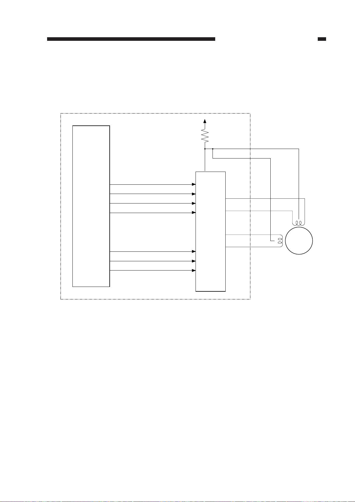
5. Controlling the Scanner/Lens Drive Motor
a. Outline
The scanner/lens drive motor (M2) is a 4-phase stepping motor. The timing at which the drive
power (SC-COM) and pulses (SC-A, SCA*, SC-B, SC-B*) are generated is controlled to turn on/
off the scanner/lens drive motor (M2) or to switch the direction of its rotation.
(Q101)
Microprocessor
DC controller PCB
A
A*
B
B*
Current switching signal 1
Current switching signal 2
Current switching signal 3
+24VU
R399
(Q109)
Motor
driver
circuit
J110
SC-COM
SC-COM
SC-A
SC-A*
SC-B
SC-B*
M2
COPYRIGHT © 1999 CANON INC. CANON PC800s/900s REV.0 AUG. 1999 PRINTED IN JAPAN (IMPRIME AU JAPON)
3-7
Page 58

CHAPTER 3 EXPOSURE SYSTEM
b. Operations
The microprocessor (Q101) mounted on the DC controller PCB receives instructions from the
control panel PCB copying mode settings (e.g., reproduction ratio). In response, it applies drive
pulses to the scanner/lens drive motor (M2) through the motor driver circuit.
The scanner motor is a 4-phase stepping motor, and changes the direction and speed of its
rotation according to the sequence and frequency of drive pulses (SC-A*through SC-B*).
The motor drive voltage is switched on and off by pulse signals (A through B*) generated by
the microprocessor (Q101). Any of these pulse signals is generated when the motor is in operation,
while no pulse signal is generated when the motor is at rest.
The current switching signals from 1 to 3 generated by the microprocessor (Q101) are used to
control the current flowing to the motor so that it varies according to the state of the scanner and the
lens.
Forwarding the
scanner
Current switching signal 1
Current switching signal 2
Current switching signal 3
Starting the lens
0
0
0
Moving the lens
0
0
1
Reversing the
scanner
0
1
1
c. Detecting Overcurrent for the Scanner/Lens Drive Motor
If overcurrent flows to the scanner/lens drive motor for some reason, the fuse (R339) on the DC
controller PCB will blow to cut the power to the motor.
Caution:
The fuse (R339) will not recover once it has blown.
1
1
1
3-8
COPYRIGHT © 1999 CANON INC. CANON PC800s/900s REV.0 AUG. 1999 PRINTED IN JAPAN (IMPRIME AU JAPON)
Page 59
CHAPTER 3 EXPOSURE SYSTEM
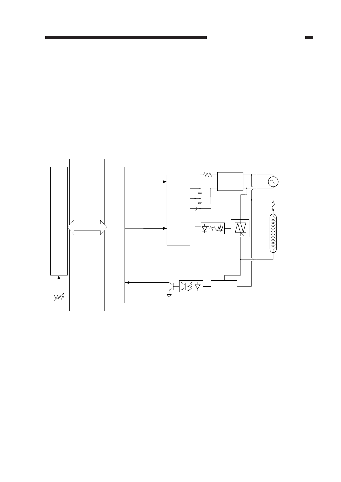
(Q101)
Serial
communication
VR107
DC controller PCB
Microprocessor
(Q900)
Intensity adjustment
signal
PWM_1KHz
Lamp activation
signal
LAMP_ON
Activation detection
signal
LAMP_DETECT
Composite power supply PCB
9
4
2
7
(HIC001)
Phase
control
circuit
Arcing circuit
Scanning lamp
(LA1)
Thermal fuse
(FU1)
Activation detection circuit
Rectifying
circuit
Microprocessor
Rectifying
circuit
+
-
+
-
II. EXPOSURE SYSTEM
A. Controlling the Scanning Lamp
1. Outline
Figure 3-201 shows the circuit used to control the scanning lamp, and has the following func-
tions:
• Turning on/off the scanning lamp.
• Controlling the intensity of the scanning lamp.
• Monitoring the state (on/off) of the scanning lamp.
COPYRIGHT © 1999 CANON INC. CANON PC800s/900s REV.0 AUG. 1999 PRINTED IN JAPAN (IMPRIME AU JAPON)
Figure 3-201
3-9
Page 60

CHAPTER 3 EXPOSURE SYSTEM
2. Operations
a. Turning On/Off the Scanning Lamp
The DC controller PCB and the composite power supply exchange signals in serial communication to control the scanning lamp. According to the scanner lamp active voltage signal, the microprocessor (Q900) on the composite power supply PCB controls the intensity adjustment signal
(PWM_1KHz) and the lamp activation signal (LAMP_ON) to turn on/off the scanning lamp
(LA1).
When LAMP_ON is ‘0’,
The phase control circuit turns on.
The arcing circuit turns on.
The scanning lamp turns on.
When LAMP_ON is ‘1’,
The phase control circuit turns off.
The arcing circuit turns off.
The scanning lamp turns off.
3-10
COPYRIGHT © 1999 CANON INC. CANON PC800s/900s REV.0 AUG. 1999 PRINTED IN JAPAN (IMPRIME AU JAPON)
Page 61
CHAPTER 3 EXPOSURE SYSTEM
b. Controlling the Intensity of the Scanning Lamp
The intensity of the lamp is controlled by the scanning lamp active voltage signal sent by the
DC controller PCB in serial.
The microprocessor (Q900) on the composite power supply PCB sends the intensity adjustment signal (PWM_1KHz) in response to the scanning lamp active voltage signal. In turn, the
phase control circuit (HIC 001) controls the voltage supplied to the scanning lamp.
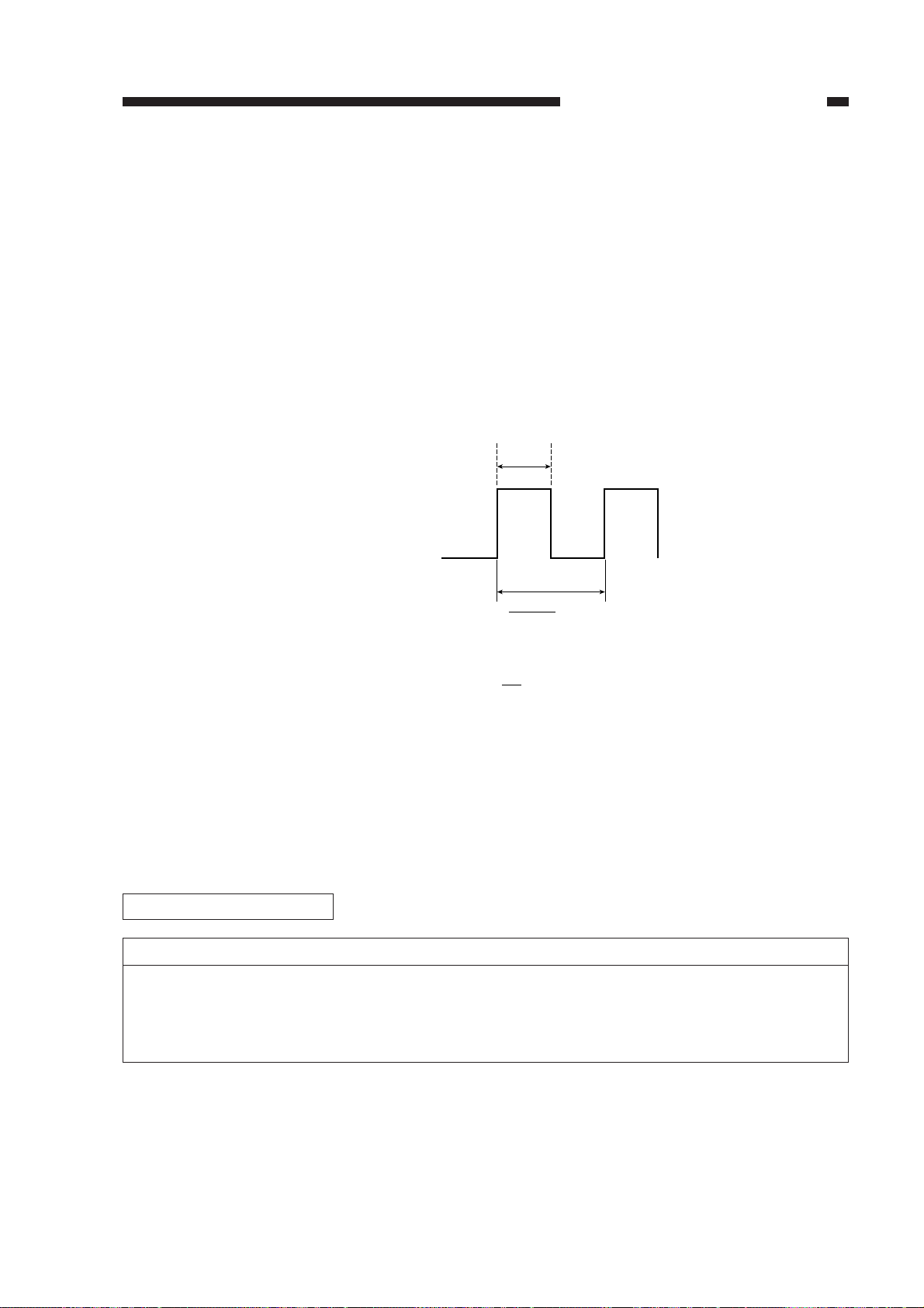
The PWM_1KHz signal varies according to the setting of VR107 mounted on the DC controller PCB between 10% and 90% in terms of pulse duty ratio or between 50.5 and 80 V for the 120 V
model (between 85.7 and 145.8 V for the 220/240 V model) in terms of actual voltage by way of
phase control.
However, the intensity remains a specific value for AE exposure so that it is 56 V for the 120 V
model (108.5 V for the 220/240 V model) in terms of actual voltage.
t [msec]
1
1k
ON
1kHz
1
OFF
[msec]
<PWM_1KHz signal>
Pulse duty= t/ × 100 [%]
Figure 3-202
c. Monitoring the Activation of the Scanning Lamp
The activation detection signal (LAMP_DETECT) is sent to the microprocessor (Q900) on the
composite power supply PCB as long as the scanning lamp remains on.
The composite power supply PCB sends the lamp activation signal to the DC controller PCB in
serial by way of monitoring the activation of the scanning lamp (LA1).
Related Error Code
E220
• The lamp activation detection signal is not detected for 1 sec or more although the scanning lamp activation signal has been sent.
• The lamp activation detection signal has been detected for 1 sec or more although the
scanning lamp activation signal is not sent.
If an error has been detected, the power switch will be turned off after indicating an error code
for 2 sec.
COPYRIGHT © 1999 CANON INC. CANON PC800s/900s REV.0 AUG. 1999 PRINTED IN JAPAN (IMPRIME AU JAPON)
3-11
Page 62

CHAPTER 3 EXPOSURE SYSTEM
III. DISASSEMBLY/ASSEMBLY
As needed, disassemble/assemble the machine with the following in mind:
!
Before starting the work, turn off the power switch and disconnect the power plug for
1.
safety.
2. Unless otherwise instructed, assemble the parts by reversing the steps used to disassemble
it.
3. Identify the screws by type (length, diameter) and location.
4. Use the washers where necessary. (The screws used to mount the grounding wire and
Varistors come with a washer to ensure electrical continuity.)
5. As necessary, cut the harness band.
6. As a rule, do not operate the machine with any of its part removed.
7. A few of the screws used are special screws (with wider thread intervals). Do not use any
screws indiscriminately.
3-12
COPYRIGHT © 1999 CANON INC. CANON PC800s/900s REV.0 AUG. 1999 PRINTED IN JAPAN (IMPRIME AU JAPON)
Page 63
A. Scanner Drive Assembly
1. Removing the Scanner/Lens Drive
Motor
1) Remove the front lower cover.
(See Chapter 7.III.A.2.“Removing the
Front Lower Cover.”)
2) Remove the copyboard glass.
(See Chapter 7.III.C.1.“Removing the
Copyboard Glass.”)
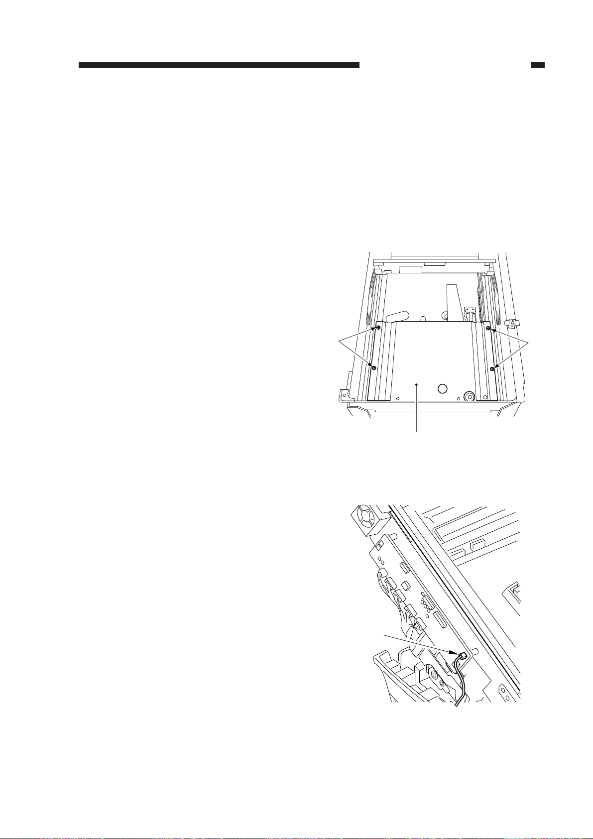
3) Remove the four screws [1], and detach
the lens cover [2].
CHAPTER 3 EXPOSURE SYSTEM
4) Disconnect the connector (J110) [3] from
the DC controller PCB.
[1]
[1]
[2]
Figure 3-301
[3]
Figure 3-302
COPYRIGHT © 1999 CANON INC. CANON PC800s/900s REV.0 AUG. 1999 PRINTED IN JAPAN (IMPRIME AU JAPON)
3-13
Page 64
CHAPTER 3 EXPOSURE SYSTEM
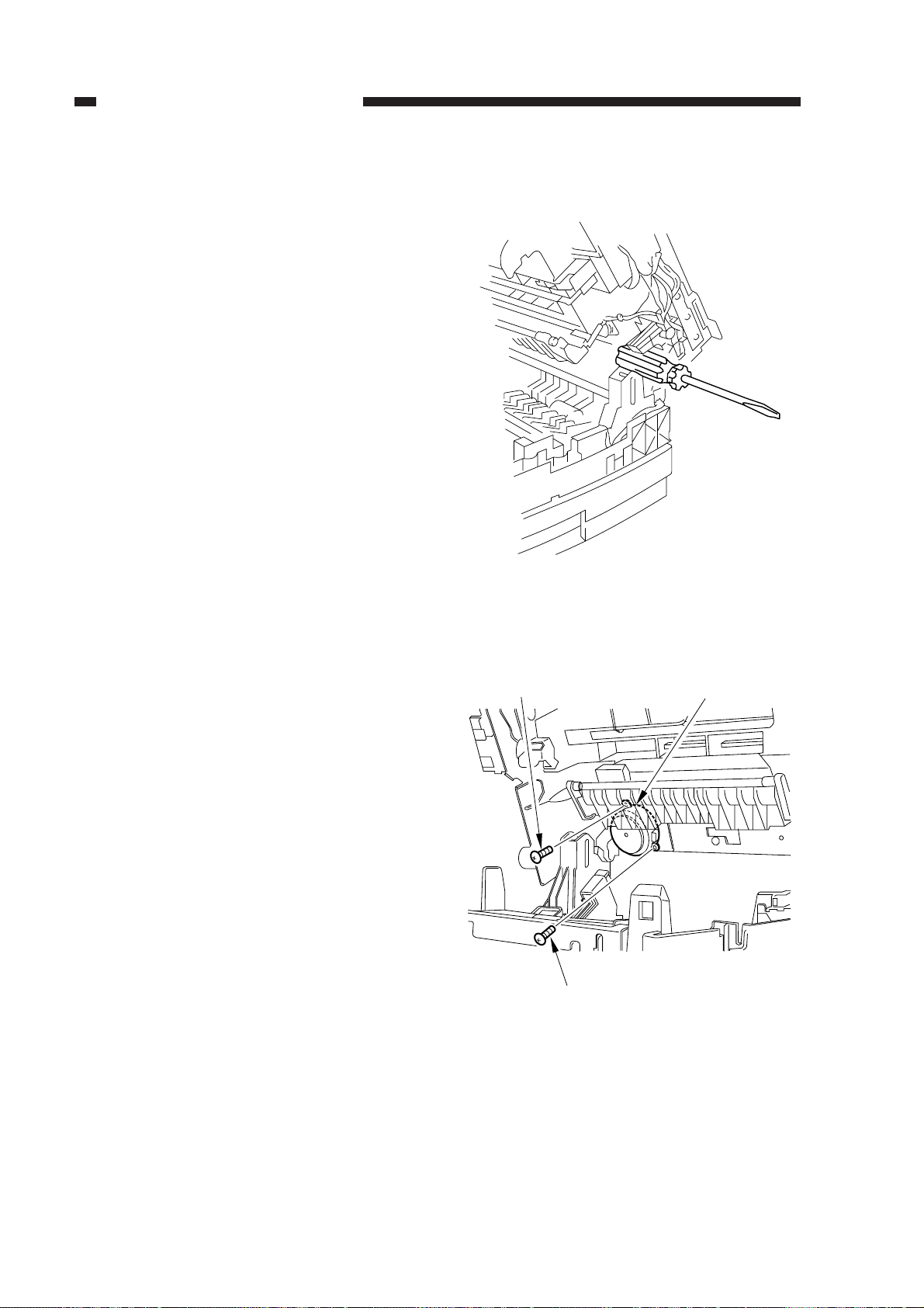
5) Open the machine’s top unit farther, and
hold it in position using the handle (about
30 mm in diameter) of a screwdriver.
6) Remove the machine’s two fixing screws
[4] from the scanner/lens drive motor [5].
[4]
Figure 3-303
[5]
[4]
Figure 3-304
3-14
COPYRIGHT © 1999 CANON INC. CANON PC800s/900s REV.0 AUG. 1999 PRINTED IN JAPAN (IMPRIME AU JAPON)
Page 65
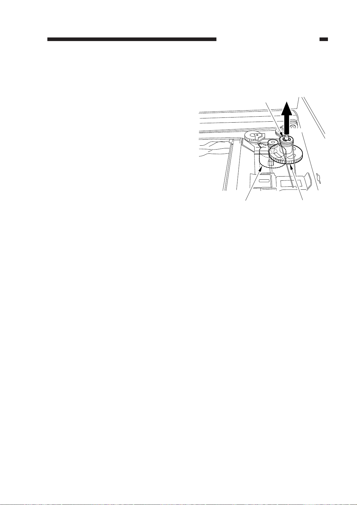
7) Free the top unit (by removing the screwdriver), and close the top unit.
8) Remove the E-ring [6]; then, lift the cable
drive pulley [7] slightly, and detach the
scanner/lens drive motor [5].
CHAPTER 3 EXPOSURE SYSTEM
[6]
Lift.
[5]
Figure 3-305
[7]
COPYRIGHT © 1999 CANON INC. CANON PC800s/900s REV.0 AUG. 1999 PRINTED IN JAPAN (IMPRIME AU JAPON)
3-15
Page 66
CHAPTER 3 EXPOSURE SYSTEM
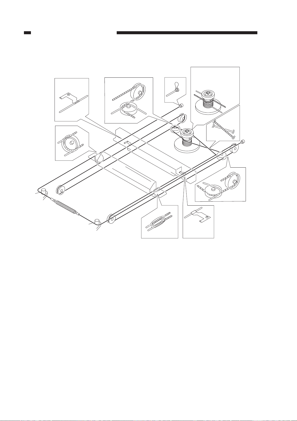
2. Outline of the Scanner Drive Cable
Wind 1.5 times.
(black cable)
Wind 7.5 times.
(silver-colored cable)
Figure 3-306
3-16
COPYRIGHT © 1999 CANON INC. CANON PC800s/900s REV.0 AUG. 1999 PRINTED IN JAPAN (IMPRIME AU JAPON)
Page 67
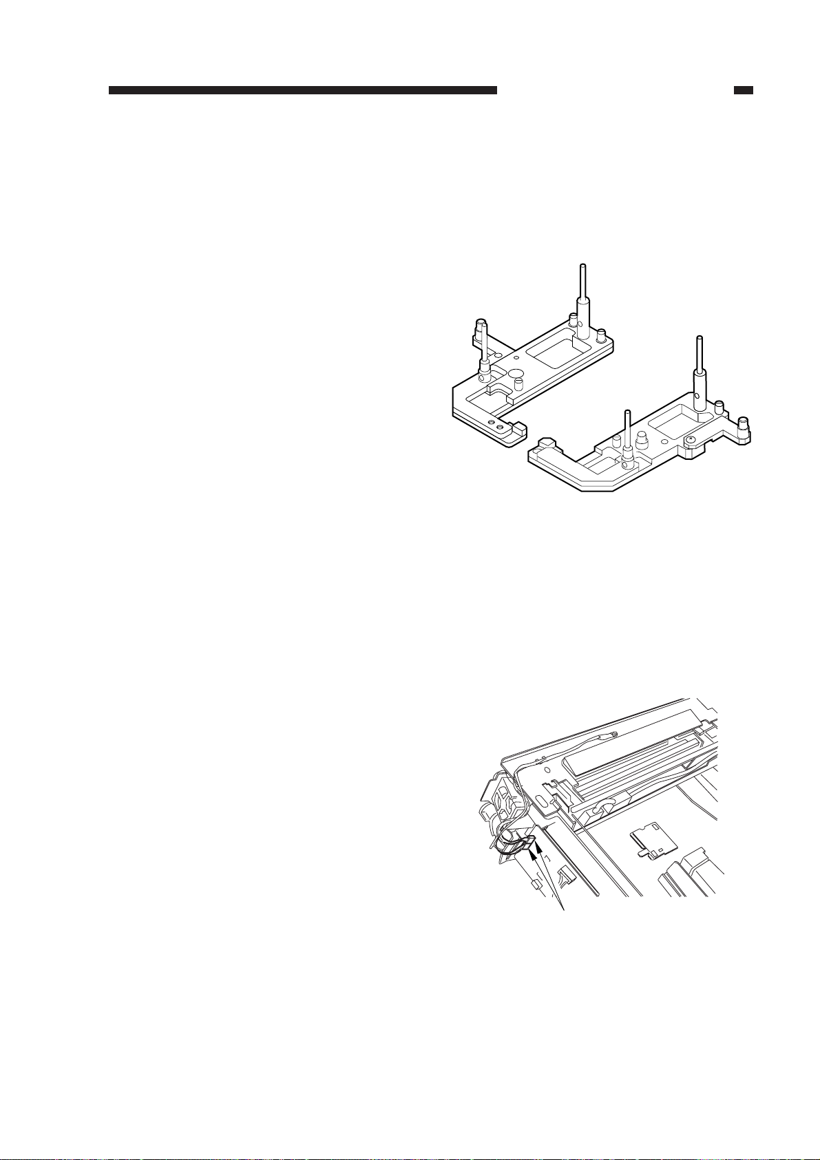
3. Routing the Scanner Drive Cable
a. Before Starting the Work
Prepare the following:
• Mirror positioning tool
• Cable clip
• Adhesive tape
1) Set the mirror positioning tool as shown.
CHAPTER 3 EXPOSURE SYSTEM
2) Prepare about five strips of adhesive tape
(each one about 20 × 50 mm).
3) Remove the copyboard glass.
(See Chapter 7.III.C.1.“Removing the
Copyboard Glass.”)
4) Disconnect the connectors (J101, J131)
[1] from the DC controller PCB.
Figure 3-307
[1]
Figure 3-308
COPYRIGHT © 1999 CANON INC. CANON PC800s/900s REV.0 AUG. 1999 PRINTED IN JAPAN (IMPRIME AU JAPON)
3-17
Page 68
CHAPTER 3 EXPOSURE SYSTEM
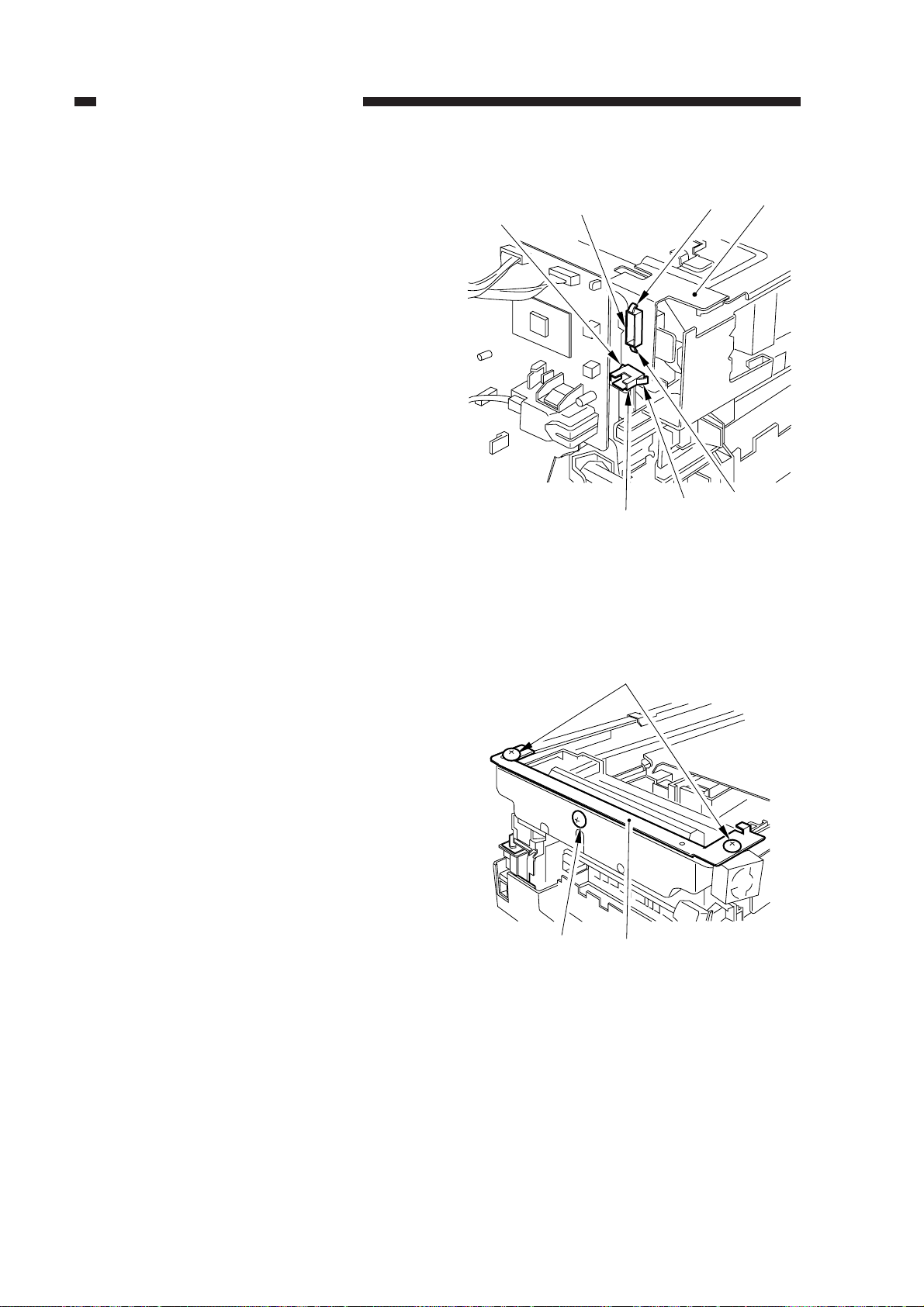
5) If the machine is equipped with an ADF,
free the hook [2], and disconnect the two
relay connectors [3] from the left upper
stay [4].
[2]
[3]
[2]
[4]
6) Remove the three screws [5], and detach
the left upper stay [4].
[3]
Figure 3-309
[5]
[5]
[4]
[2]
[2]
3-18
Figure 3-310
COPYRIGHT © 1999 CANON INC. CANON PC800s/900s REV.0 AUG. 1999 PRINTED IN JAPAN (IMPRIME AU JAPON)
Page 69
[6]
[6]
[7]
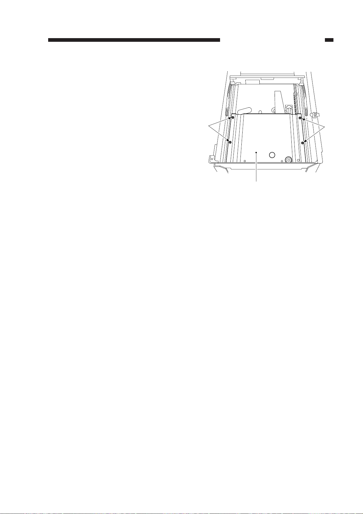
7) Remove the four screws [6], and detach
the lens cover [7].
CHAPTER 3 EXPOSURE SYSTEM
Figure 3-311
COPYRIGHT © 1999 CANON INC. CANON PC800s/900s REV.0 AUG. 1999 PRINTED IN JAPAN (IMPRIME AU JAPON)
3-19
Page 70
CHAPTER 3 EXPOSURE SYSTEM
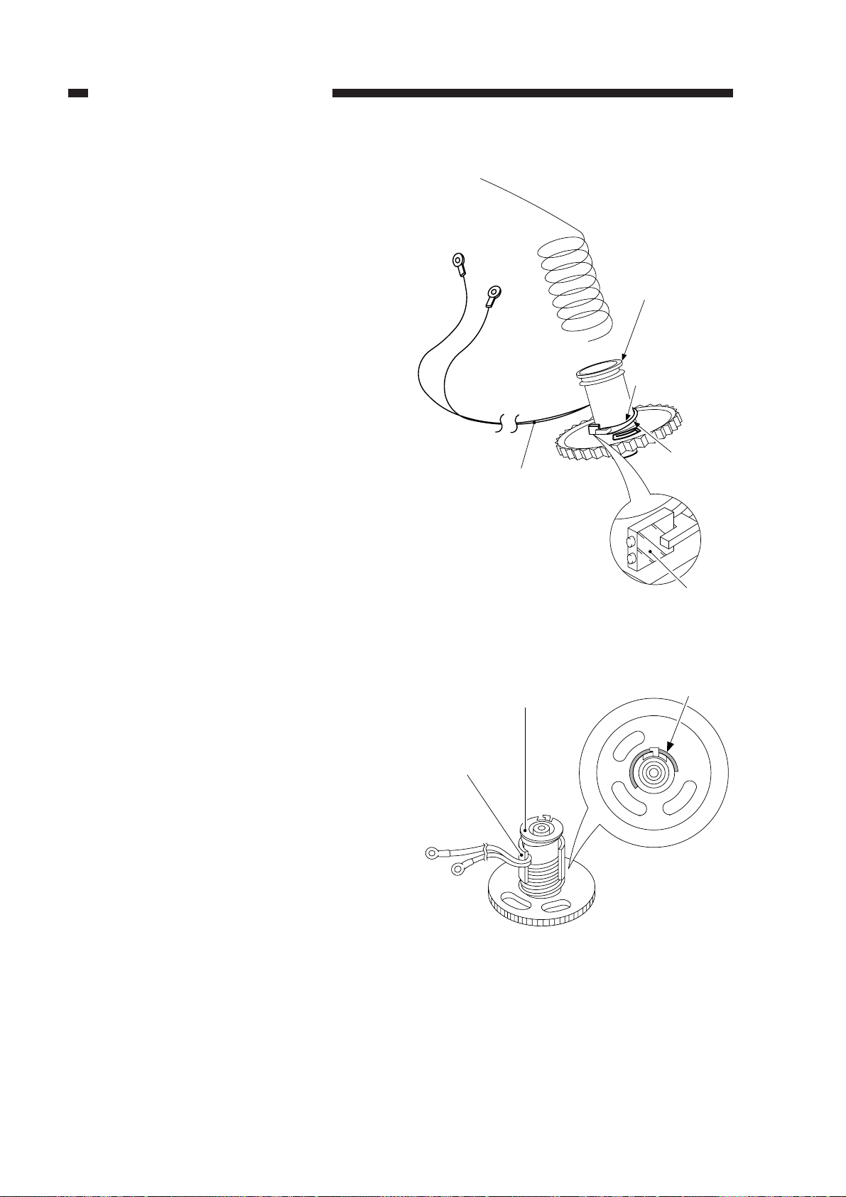
b. Routing the Reversing Cable
1) Wind the reversing cables (silver-colored)
[2] on the cable drive pulley [1] 7.5 times
with the longer end on top; then, secure it
in position with a cable clip [3].
[1]
Longer end
[3]
[2]
Shorter end
Face with a marking
Figure 3-312
[3]
[1]
Top View
3-20
Figure 3-313
COPYRIGHT © 1999 CANON INC. CANON PC800s/900s REV.0 AUG. 1999 PRINTED IN JAPAN (IMPRIME AU JAPON)
Page 71
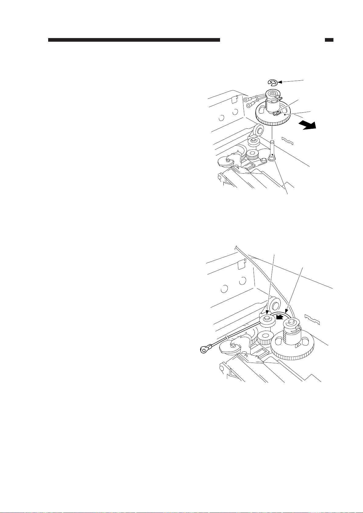
[7]
[6]
2) Put the cable drive pulley [1] into the shaft
[4], and secure it in position with an Ering [5].
When putting the cable drive pulley into
the shaft, be sure that the hook is at the
front.
CHAPTER 3 EXPOSURE SYSTEM
[5]
Hook
[1]
(front)
[4]
Figure 3-314
3) Hook the shorter end [6] on the pulley [7].
Figure 3-315
COPYRIGHT © 1999 CANON INC. CANON PC800s/900s REV.0 AUG. 1999 PRINTED IN JAPAN (IMPRIME AU JAPON)
3-21
Page 72
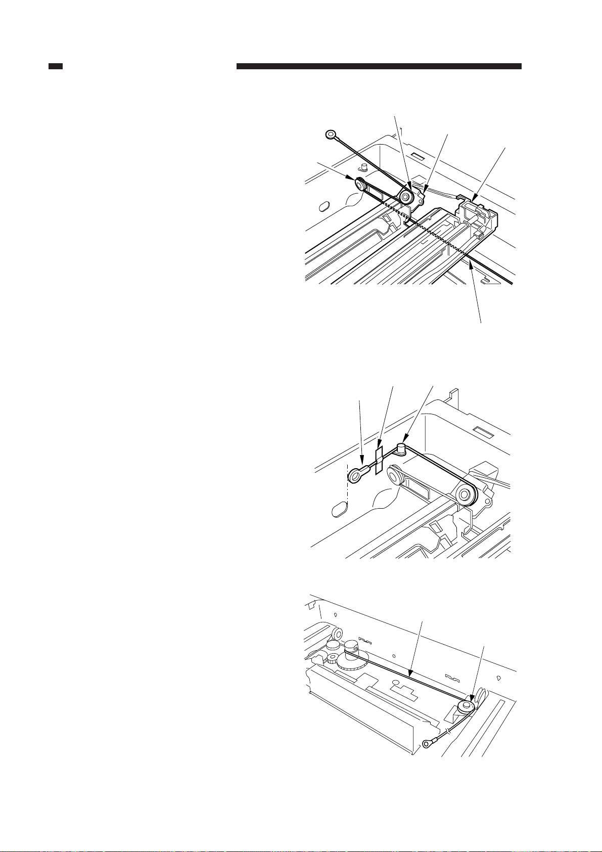
CHAPTER 3 EXPOSURE SYSTEM
4) Lead the shorter end [6] under the No. 1
mirror mount [8] and the No. 2/3 mirror
mount [9]; then, hook it on the left rear
pulley [10] and the pulley [11] of the No.
2/3 mirror mount.
5) After fitting the shorter end [6] on the
cable hook [12], secure its end with adhesive tape [13].
Be sure that the secured end of the cable is
found where the hole in the left side plate
and the tip of the cable matches.
[10]
[11]
Figure 3-316
[13]
[6]
[9]
[8]
[6]
[12]
6) Lead the longer end [14] along the cable
drive pulley, and hook it on the pulley
[15] on the right front side.
3-22
COPYRIGHT © 1999 CANON INC. CANON PC800s/900s REV.0 AUG. 1999 PRINTED IN JAPAN (IMPRIME AU JAPON)
Figure 3-317
[14]
[15]
Figure 3-318
Page 73
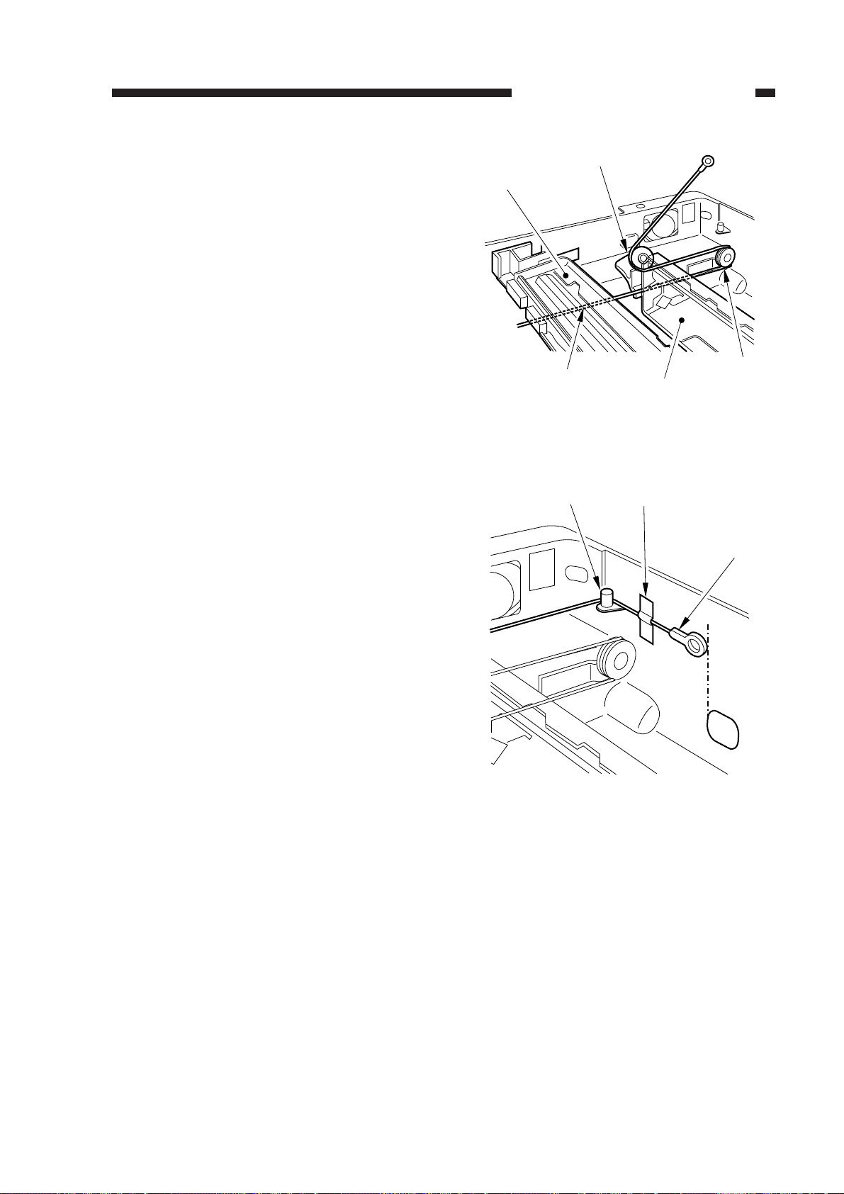
CHAPTER 3 EXPOSURE SYSTEM
7) Lead the longer end [14] under the No. 1
mirror mount [8] and the No. 2/3 mirror
mount [9]; then, hook it on the pulley [16]
on the left front side and the pulley [17] of
the No. 2/3 mirror mount.
8) Hook the longer end [14] on the cable
hook [18]; then, secure its end to the left
side with adhesive tape [19].
Be sure that the secured end of the cable is
found where the hole in the left side plate
and the tip of the cable matches.
[8]
[17]
[14]
Figure 3-319
[18]
[19]
[16]
[9]
[14]
Figure 3-320
COPYRIGHT © 1999 CANON INC. CANON PC800s/900s REV.0 AUG. 1999 PRINTED IN JAPAN (IMPRIME AU JAPON)
3-23
Page 74
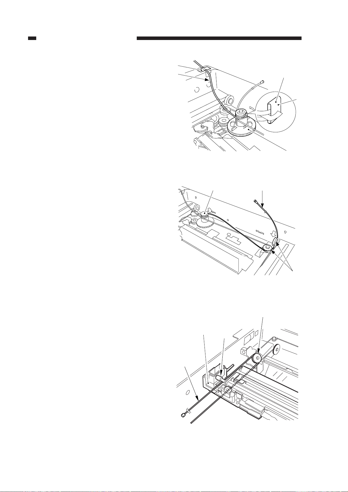
CHAPTER 3 EXPOSURE SYSTEM
c. Routing the Forwarding Cable
1) Fit the longer end forwarding cable
(black) [2] on the top hook of the cable
drive pulley [1], and wind it 1.5 times.
Then, secure the shorter end [3] as shown
with adhesive tape [4].
2) Lead the longer end [5] along the cable
drive pulley [1] as shown, and hook it on
the pulley [6] on the right front side.
[4]
[3]
Face without a marking
[2]
[1]
Figure 3-321
[5][1]
3) Lead the longer end [5] under the No. 1
mirror mount [7]; then, hook it on the pulley [8] of the No. 2/3 mirror mount, and
lead it between the No. 1 mirror mount [7]
and the scanning lamp [9].
[5]
Figure 3-322
[7]
Figure 3-323
[6]
[8]
[9]
3-24
COPYRIGHT © 1999 CANON INC. CANON PC800s/900s REV.0 AUG. 1999 PRINTED IN JAPAN (IMPRIME AU JAPON)
Page 75
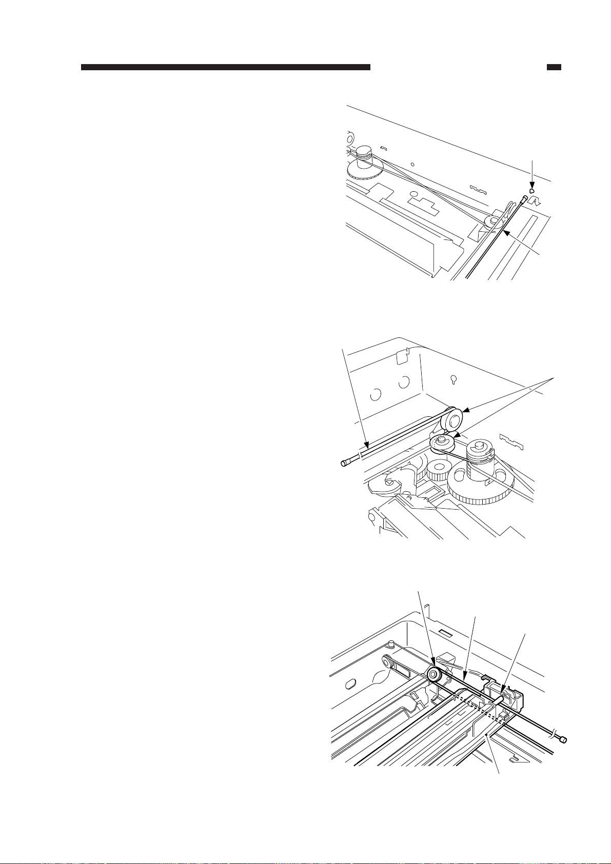
[11]
[3]
[7]
[9]
[3]
[12]
4) Hook the end of the longer end [5] on the
hole [10] on the right side.
5) Free the shorter end [3], and hook it on the
pulley [11] on the right rear side.
CHAPTER 3 EXPOSURE SYSTEM
[10]
[5]
Figure 3-324
Figure 3-325
6) Lead the shorter end [3] under the No. 1
mirror mount [7], and hook it on the pulley [12] of the No. 2/3 mirror mount as
shown; then, lead it between the No. 1
mirror mount [7] and the scanning lamp
[9].
Figure 3-326
COPYRIGHT © 1999 CANON INC. CANON PC800s/900s REV.0 AUG. 1999 PRINTED IN JAPAN (IMPRIME AU JAPON)
3-25
Page 76
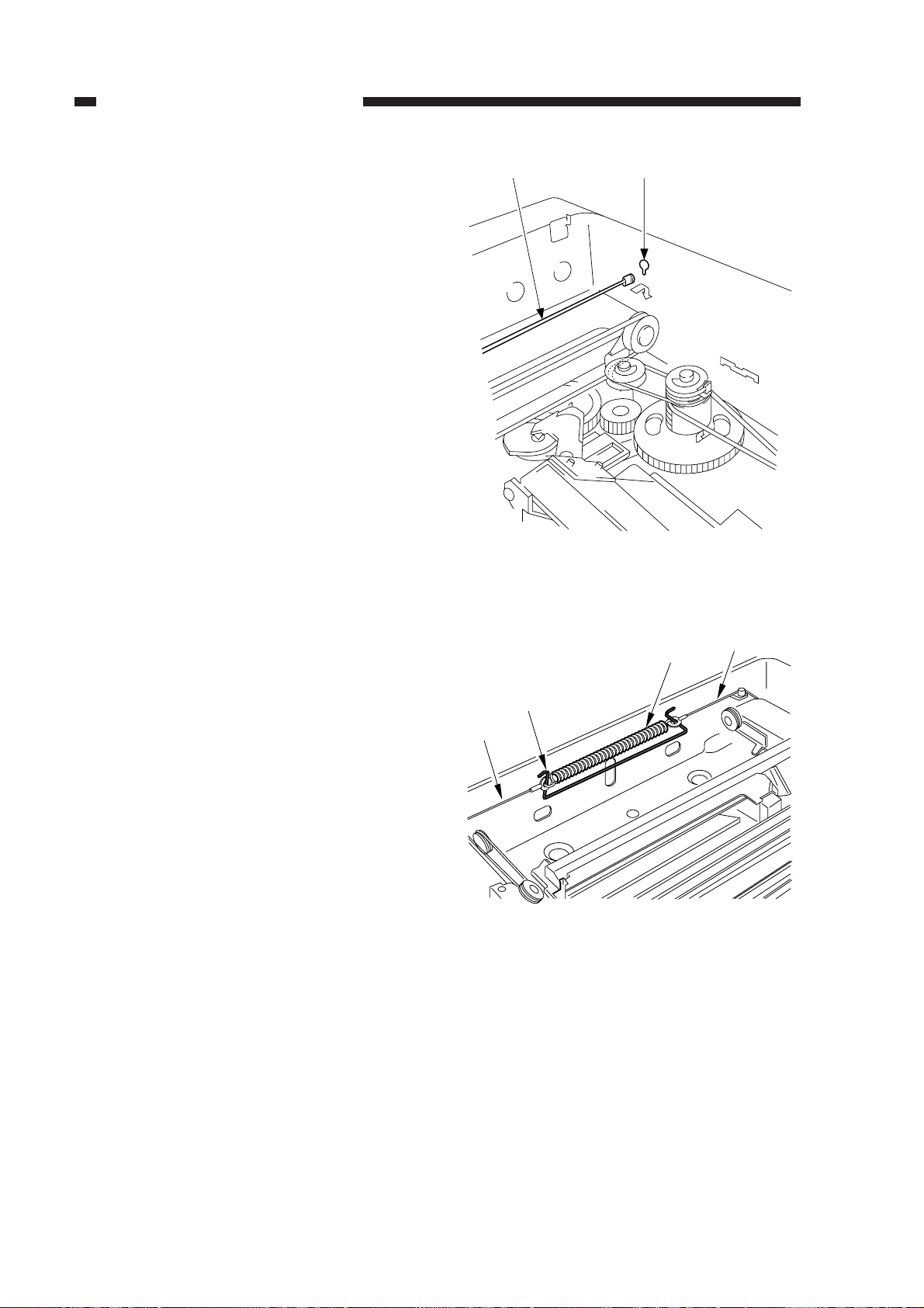
CHAPTER 3 EXPOSURE SYSTEM
7) Hook the end of the shorter end [3] on the
hole [13] on the right side.
8) Free the shorter end [3] and the longer end
[5] (reversing cable), and connect both
with a spring [14]; then, fit the stopper
[15].
[3] [13]
Figure 3-327
[15]
[14]
[3]
[5]
Figure 3-328
3-26
COPYRIGHT © 1999 CANON INC. CANON PC800s/900s REV.0 AUG. 1999 PRINTED IN JAPAN (IMPRIME AU JAPON)
Page 77

9) Detach the pulley clip [16] from the cable
drive pulley [1].
CHAPTER 3 EXPOSURE SYSTEM
[1] [16]
Figure 3-329
COPYRIGHT © 1999 CANON INC. CANON PC800s/900s REV.0 AUG. 1999 PRINTED IN JAPAN (IMPRIME AU JAPON)
3-27
Page 78
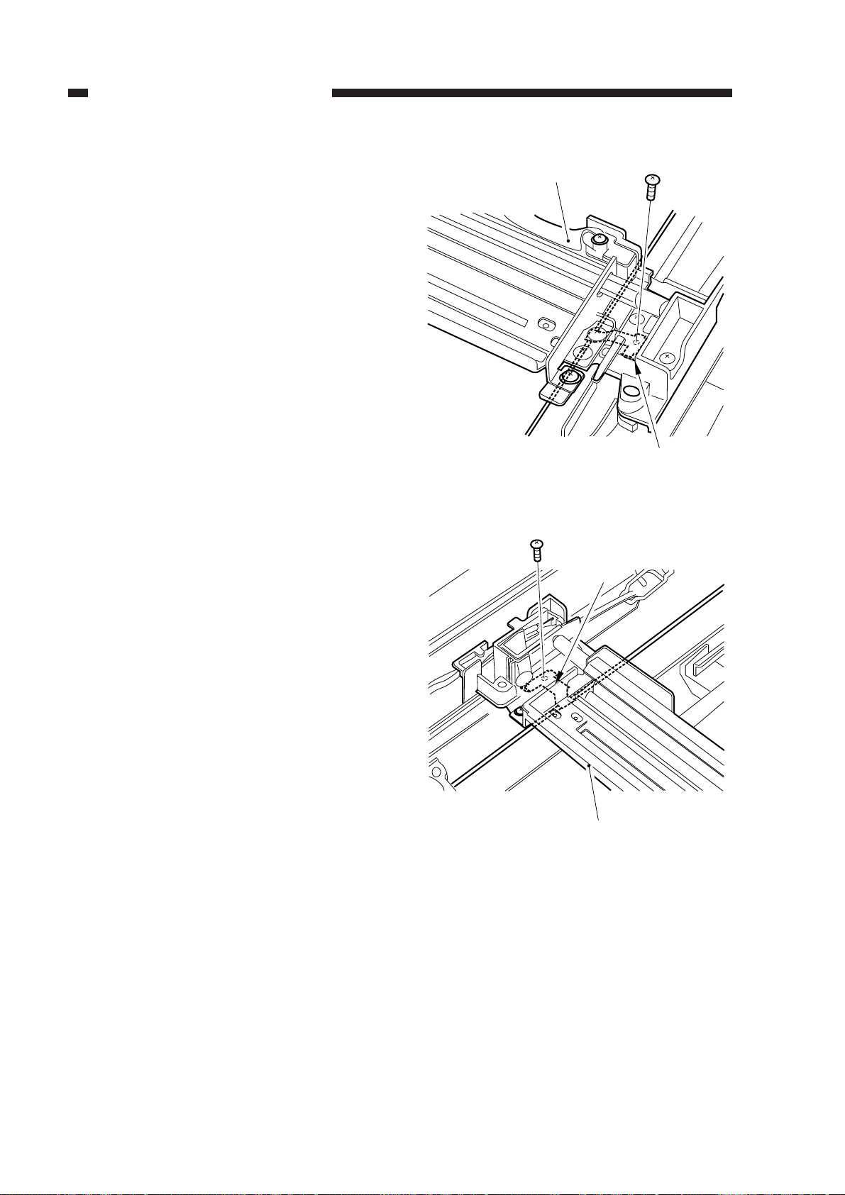
CHAPTER 3 EXPOSURE SYSTEM
d. Positioning the No. 1 Mirror Mount
1) Fix the rear and the front of the No. 1 mirror mount [1] temporarily to the metal fixing [2] of the forwarding cable.
[1]
[2]
Figure 3-330 (rear)
[2]
[1]
Figure 3-331 (front)
3-28
COPYRIGHT © 1999 CANON INC. CANON PC800s/900s REV.0 AUG. 1999 PRINTED IN JAPAN (IMPRIME AU JAPON)
Page 79
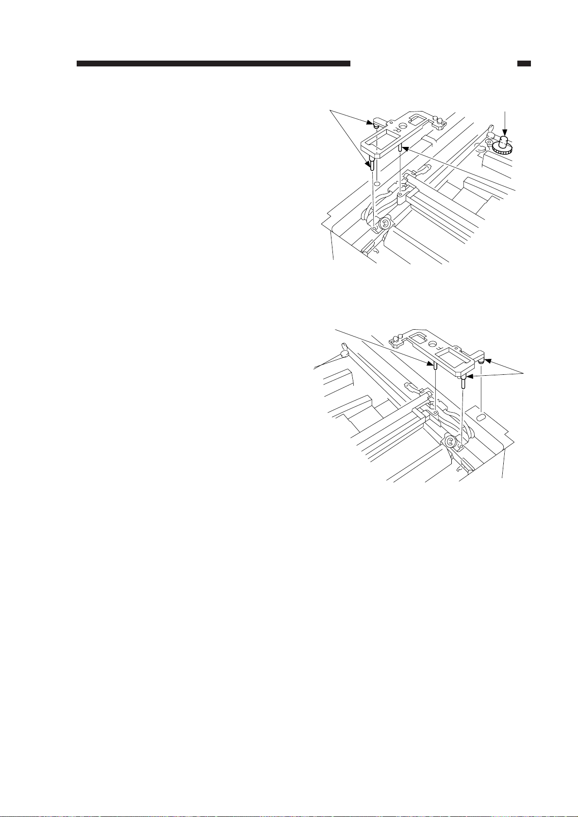
CHAPTER 3 EXPOSURE SYSTEM
[3]
[3]
2) Turn the cable drive pulley [4] so that the
three shafts [3] of the mirror positioning
tool for rear and front is as shown.
[3]
[4]
[3]
Figure 3-332 (rear)
Figure 3-333 (front)
COPYRIGHT © 1999 CANON INC. CANON PC800s/900s REV.0 AUG. 1999 PRINTED IN JAPAN (IMPRIME AU JAPON)
3-29
Page 80
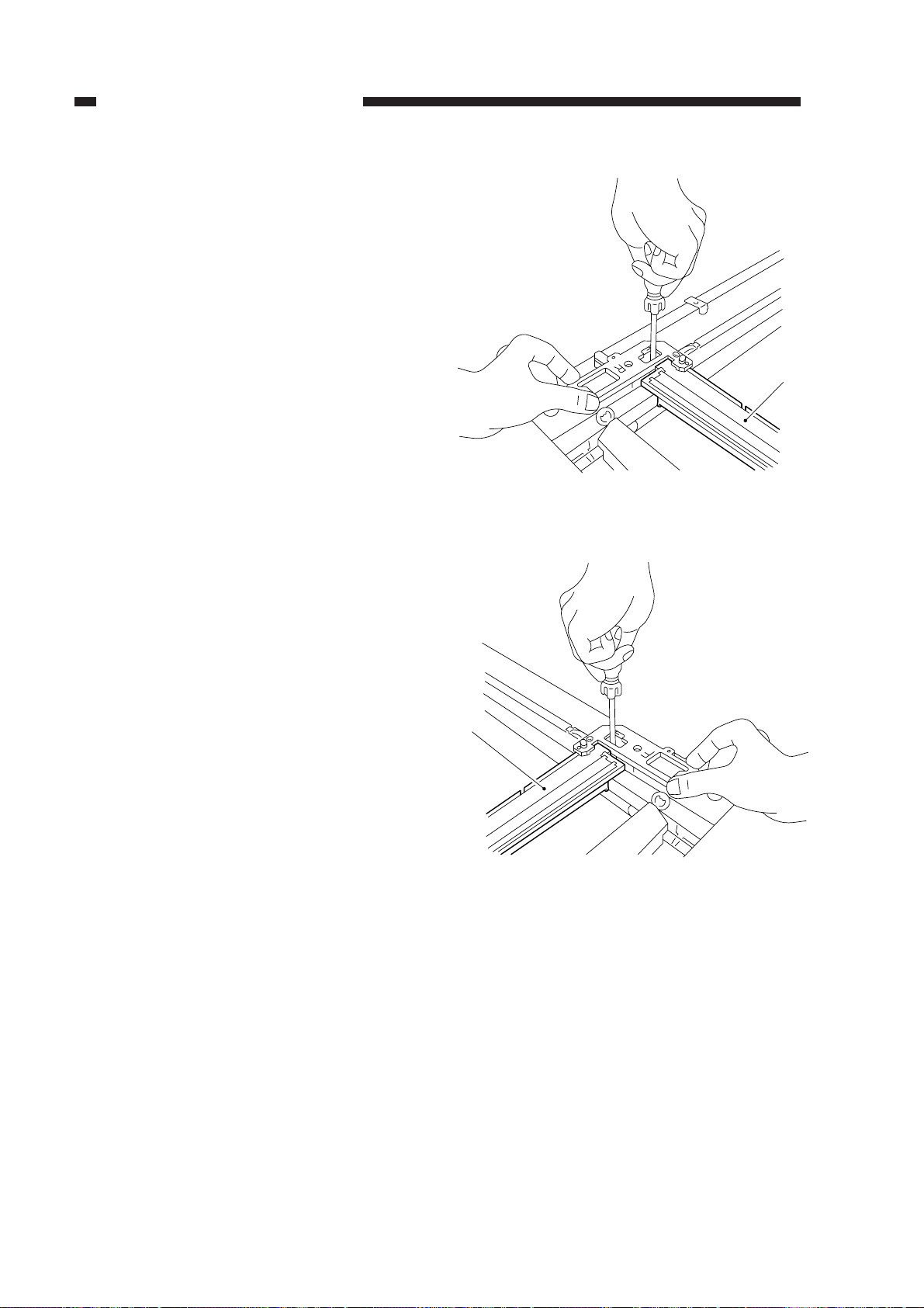
CHAPTER 3 EXPOSURE SYSTEM
3) While keeping the condition of step 2),
tighten the positioning screw on the rear
and front of the No. 1 mirror mount [1].
[1]
Figure 3-334 (rear)
[1]
Figure 3-335 (front)
3-30
COPYRIGHT © 1999 CANON INC. CANON PC800s/900s REV.0 AUG. 1999 PRINTED IN JAPAN (IMPRIME AU JAPON)
Page 81
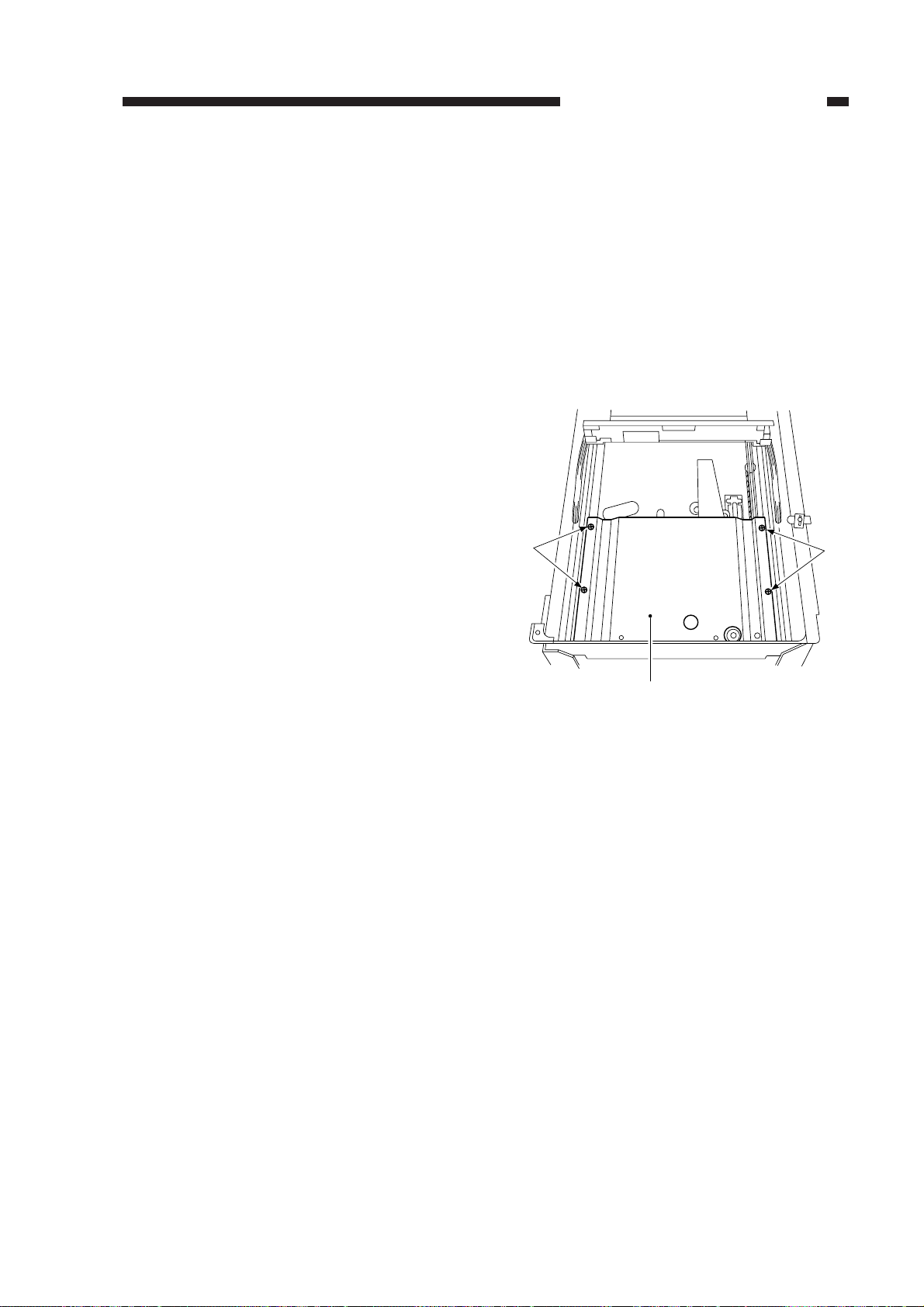
B. Lens Drive Assembly
1. Removing the Lens Cable
1) Turn on the power; when the lens has
moved to the Direct position, disconnect
the power plug.
2) Remove the copyboard glass.
(See Chapter 7.III.C.1.“Removing the
Copyboard Glass.”)
3) Remove the main drive assembly.
(See Chapter 7.III.D.2.“Removing the
Main Drive Assembly.”)
4) Remove the four screws [1], and detach
the lens cover [2].
CHAPTER 3 EXPOSURE SYSTEM
[1]
[1]
[2]
Figure 3-336
COPYRIGHT © 1999 CANON INC. CANON PC800s/900s REV.0 AUG. 1999 PRINTED IN JAPAN (IMPRIME AU JAPON)
3-31
Page 82
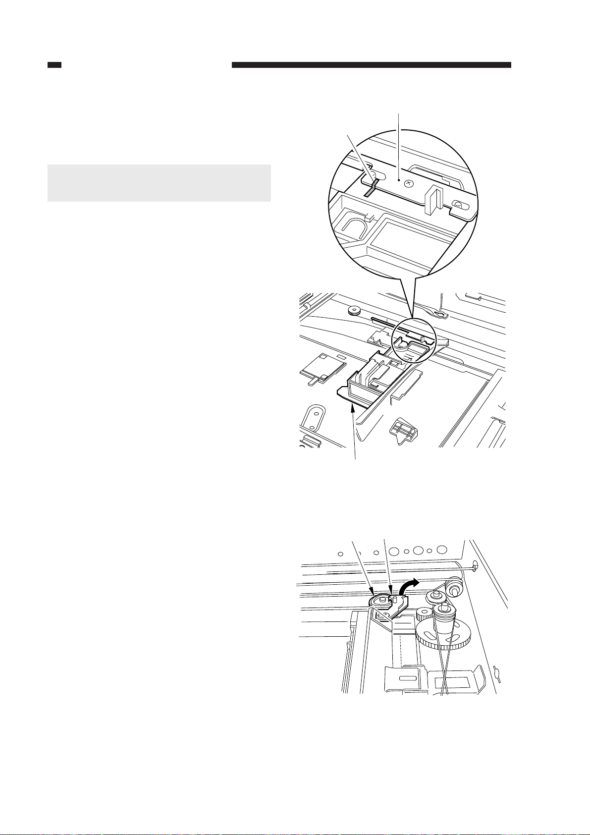
CHAPTER 3 EXPOSURE SYSTEM
5) Mark the position of the lens cable fixing
plate [3] and the lens mount [4] with a
scriber.
Caution:
When routing the lens cable, be sure to
refer to the marking made with a scriber.
[3]
Marking
6) Disengage the lever [5] of the No. 4/5 mirror mount and the gear [6].
[4]
Figure 3-337
[6]
[5]
Figure 3-338
3-32
COPYRIGHT © 1999 CANON INC. CANON PC800s/900s REV.0 AUG. 1999 PRINTED IN JAPAN (IMPRIME AU JAPON)
Page 83
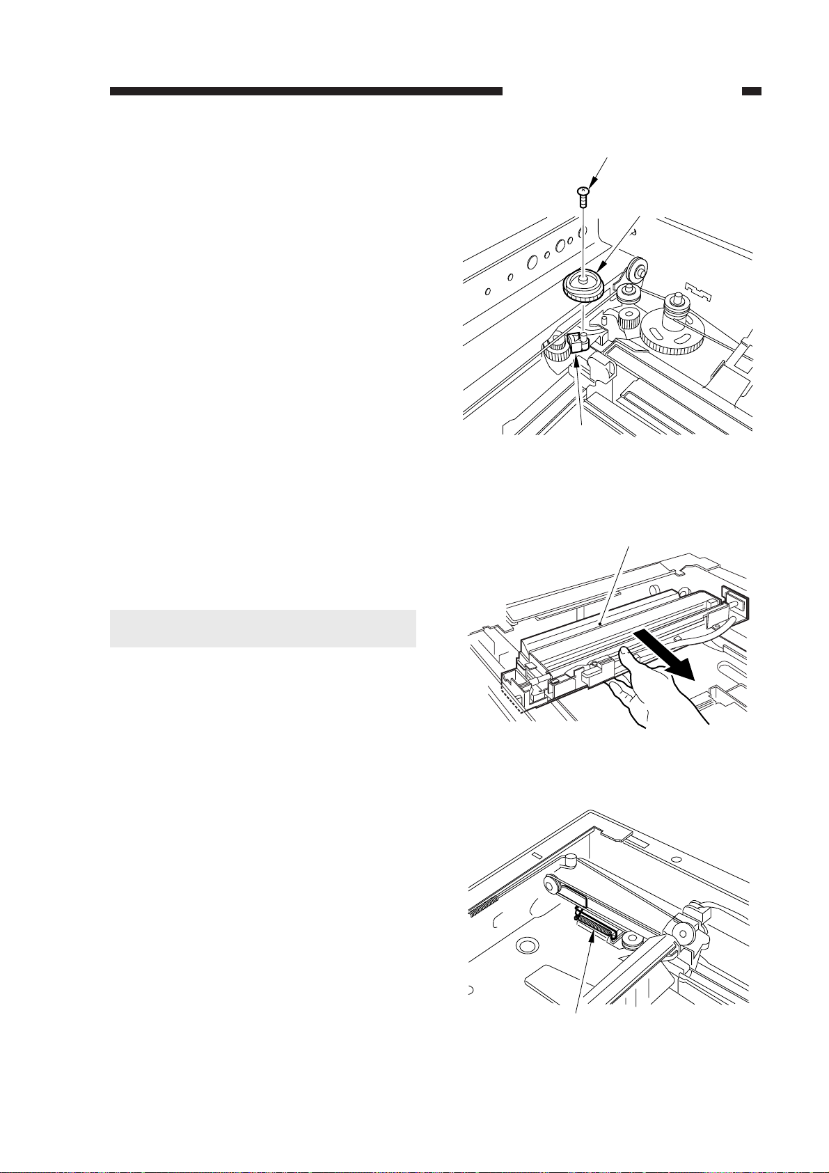
CHAPTER 3 EXPOSURE SYSTEM
7) Remove the screw [7], and detach the cam
gear [6] and the cable retainer [8].
8) Holding the middle of the No. 1 mirror
mount [9], move it to the center of the
machine.
[7]
[6]
[8]
Figure 3-339
[9]
Caution:
Do not hold the reflecting plate.
9) Remove the spring [10].
Figure 3-340
[10]
Figure 3-341
COPYRIGHT © 1999 CANON INC. CANON PC800s/900s REV.0 AUG. 1999 PRINTED IN JAPAN (IMPRIME AU JAPON)
3-33
Page 84
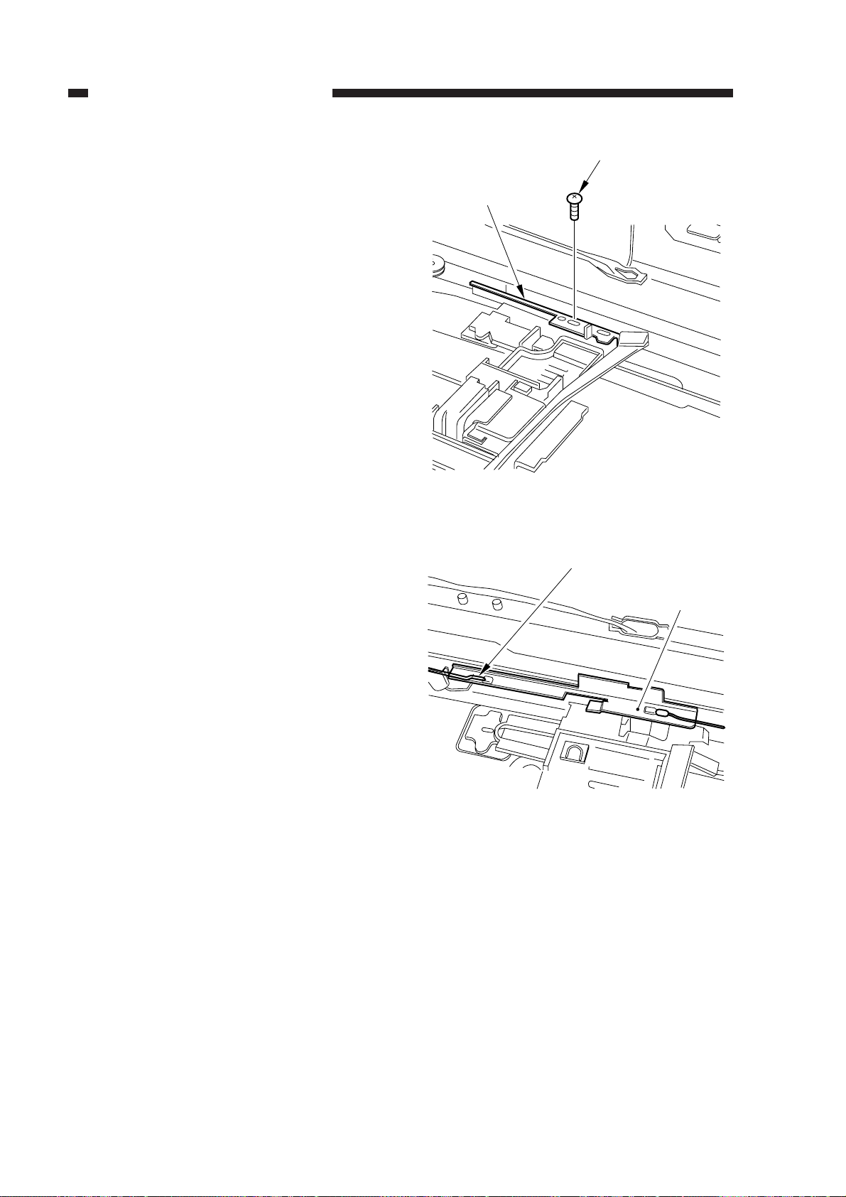
CHAPTER 3 EXPOSURE SYSTEM
10) Remove the screw [11], and detach the
lens cable fixing plate [12].
11) Free the lens cable [13] from the lens
cable fixing plate [12]; then, detach the
lens cable from the machine.
[11]
[12]
Figure 3-342
[13]
[12]
3-34
Figure 3-343
COPYRIGHT © 1999 CANON INC. CANON PC800s/900s REV.0 AUG. 1999 PRINTED IN JAPAN (IMPRIME AU JAPON)
Page 85
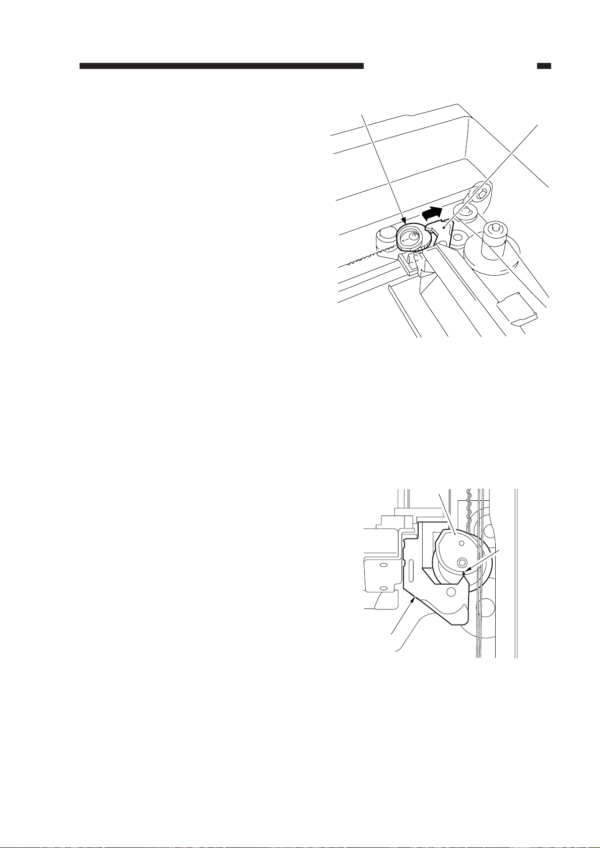
[2]
[1]
2. Routing the Lens Cable
1) After routing the lens cable, keep the lever
[1] of the No. 4/5 mirror mount disengaged from the cam gear [2] (so that the
lever will not come into contact when the
cam gear rotates).
CHAPTER 3 EXPOSURE SYSTEM
2) While keeping the condition in step 1),
turn on the power; when the No. 1 mirror
mount and the lens stopped moving, turn
off the power.
• The lens will move to the Direct posi-
tion.
3) Check to make sure that the tip of the lever [1] of the No. 4/5 mirror mount and
the marking [3] on the top face of the cam
gear [2] match; then, engage the lever [1]
and the cam gear [2].
Figure 3-344
[2]
[3]
[1]
Figure 3-345
COPYRIGHT © 1999 CANON INC. CANON PC800s/900s REV.0 AUG. 1999 PRINTED IN JAPAN (IMPRIME AU JAPON)
3-35
Page 86
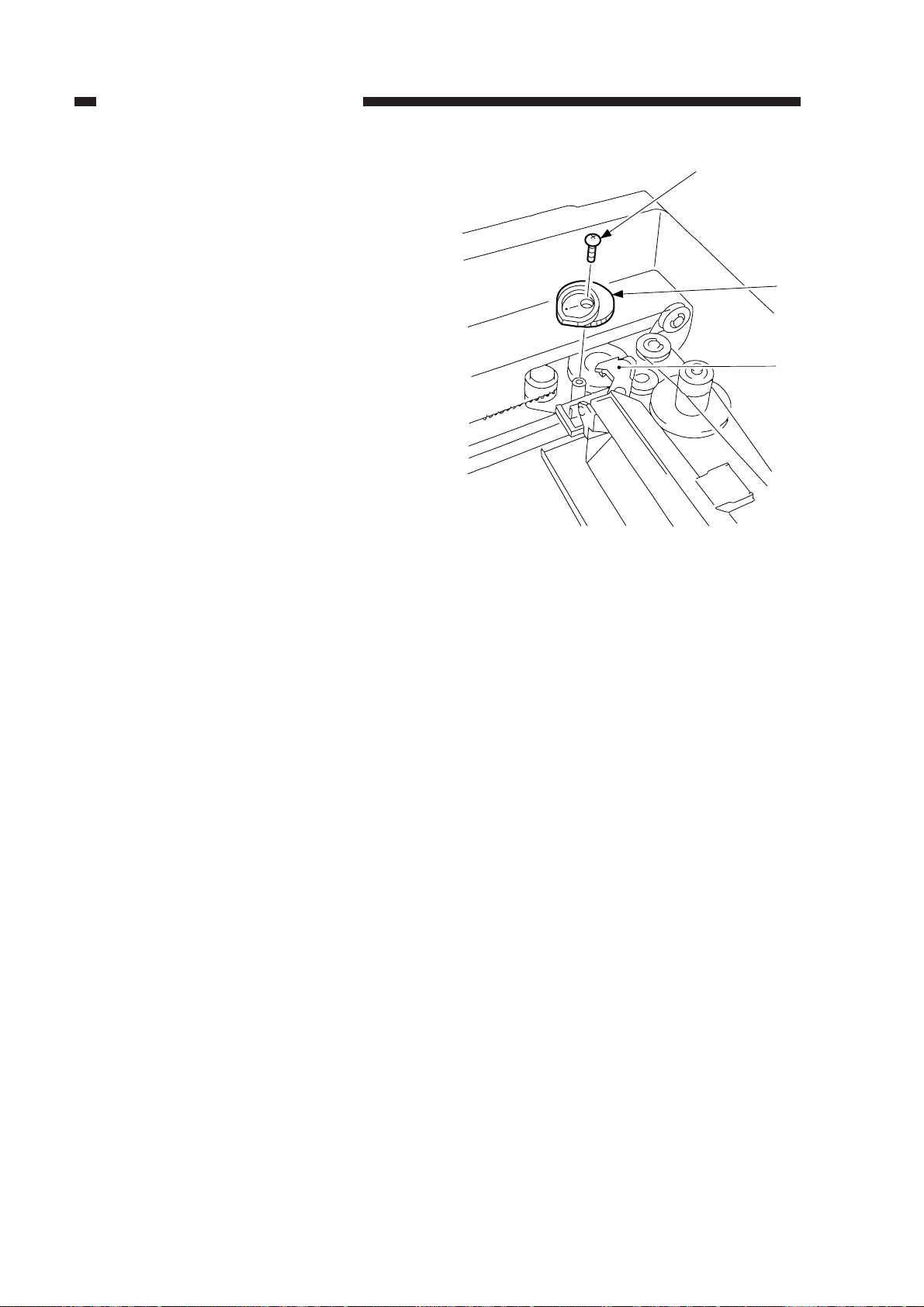
CHAPTER 3 EXPOSURE SYSTEM
4) If the tip of the lever [1] and the marking
on the cam gear [2] do not match, remove
the fixing screw [4] of the cam gear [2]
and detach the cam gear; then, mount the
cam gear once again so that the marking
on it and the tip of the lever match.
[4]
[2]
[1]
Figure 3-346
3-36
COPYRIGHT © 1999 CANON INC. CANON PC800s/900s REV.0 AUG. 1999 PRINTED IN JAPAN (IMPRIME AU JAPON)
Page 87
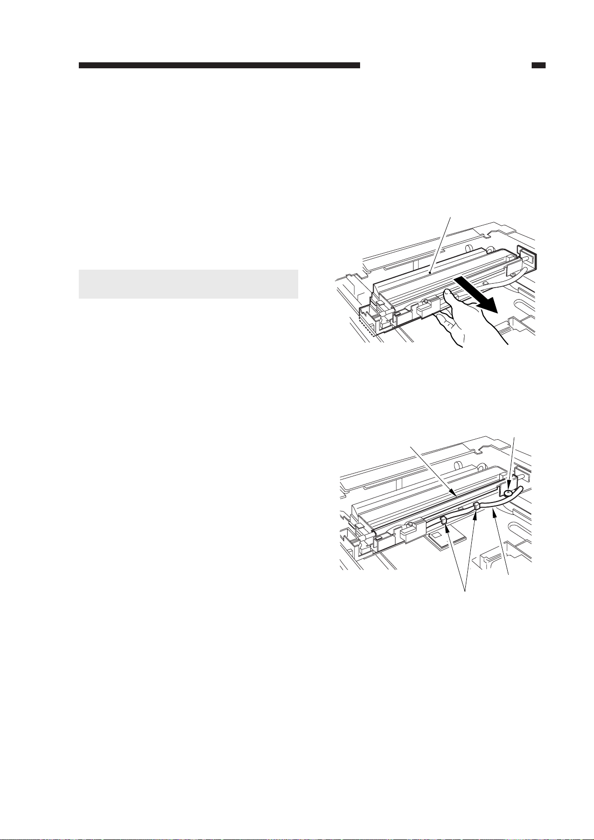
C. Exposure System
1. Removing the Scanning Lamp
1) Disconnect the power plug.
2) Remove the copyboard glass.
(See Chapter 7.III.C.1. “Removing the
Copyboard Glass.”)
3) Holding the middle of the No. 1 mirror
mount [1], move the No. 1 mirror mount
[1] to the right by about 5 cm.
Cauiton:
Do not hold the reflecting plate.
CHAPTER 3 EXPOSURE SYSTEM
[1]
4) Free the harness [3] from the guide [2];
then, remove the screw [4], and detach the
reflecting plate [5].
Figure 3-347
[4]
[5]
[3]
[2]
Figure 3-348
COPYRIGHT © 1999 CANON INC. CANON PC800s/900s REV.0 AUG. 1999 PRINTED IN JAPAN (IMPRIME AU JAPON)
3-37
Page 88
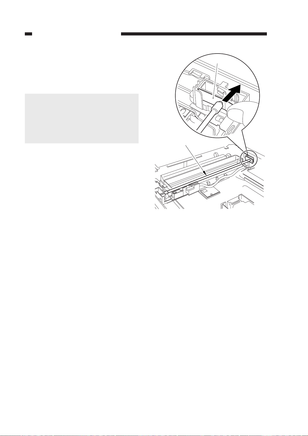
CHAPTER 3 EXPOSURE SYSTEM
5) While pushing the electrode mount [6]
found at the rear of the machine in the direction of the arrow, detach the scanning
lamp [7].
Caution:
1. Do not start the work if the scanning
lamp is hot.
2. Do not leave fingerprints on the surface of the scanning lamp.
3. If the surface of the scanning lamp is
soiled, dry wipe it.
[6]
[7]
Figure 3-349
3-38
COPYRIGHT © 1999 CANON INC. CANON PC800s/900s REV.0 AUG. 1999 PRINTED IN JAPAN (IMPRIME AU JAPON)
Page 89
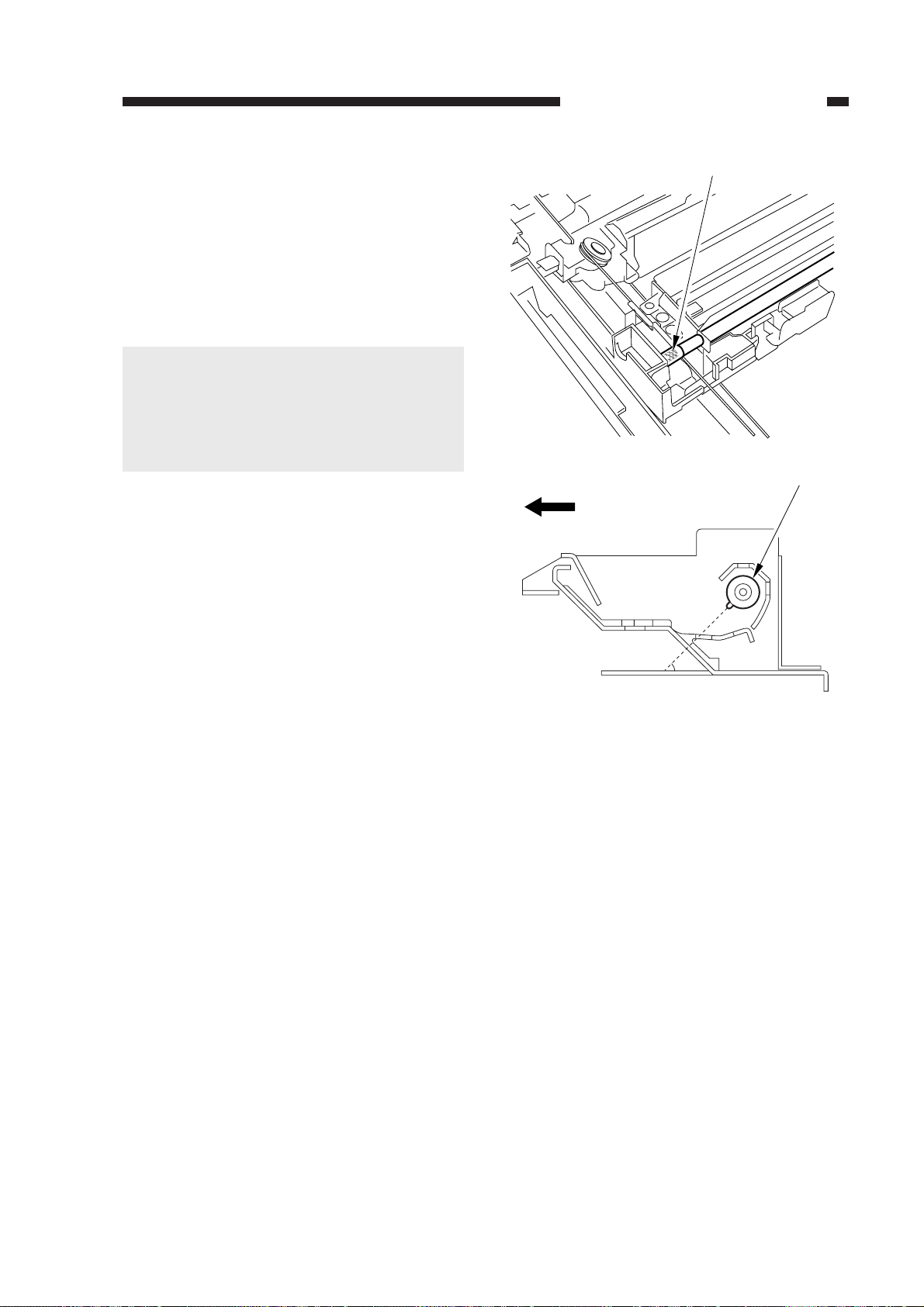
Logo mark
Scanning lamp
45 (approx.)
(mirror mount moving in reverse)
(front)
2. Points to Note When Mounting the
Lamp
When mounting the scanning lamp, be
sure that the logo mark (or the name of the
manufacturer) is toward the front. Further, be
sure that the protrusion near the middle of the
lamp is as shown.
Caution:
• Do not touch the lamp portion.
• If you have replaced the scanning lamp,
be sure to perform intensity adjustment (p.
11-42) and AE adjustment (p. 11-43).
CHAPTER 3 EXPOSURE SYSTEM
Figure 3-350
COPYRIGHT © 1999 CANON INC. CANON PC800s/900s REV.0 AUG. 1999 PRINTED IN JAPAN (IMPRIME AU JAPON)
3-39
Page 90
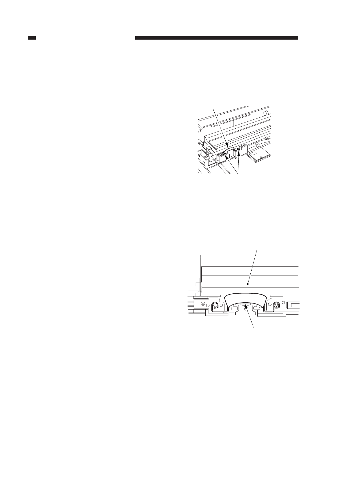
CHAPTER 3 EXPOSURE SYSTEM
3. Removing the Thermal Fuse
1) Disconnect the power plug.
2) Remove the copyboard glass.
(See Chapter 7.III.C.1.“Removing the
Copyboard Glass.”)
3) Remove the two screws [1], and detach
the thermal fuse [2].
[2]
[1]
Figure 3-351
4. Points to Note When Mounting the
Fuse
When mounting the thermal fuse, be sure
that the thermal fuse is oriented as shown.
Make sure that the fuse is in contact with
the reflecting plate.
Reflecting plate
(front)
Thermal fuse
Figure 3-352
3-40
COPYRIGHT © 1999 CANON INC. CANON PC800s/900s REV.0 AUG. 1999 PRINTED IN JAPAN (IMPRIME AU JAPON)
Page 91
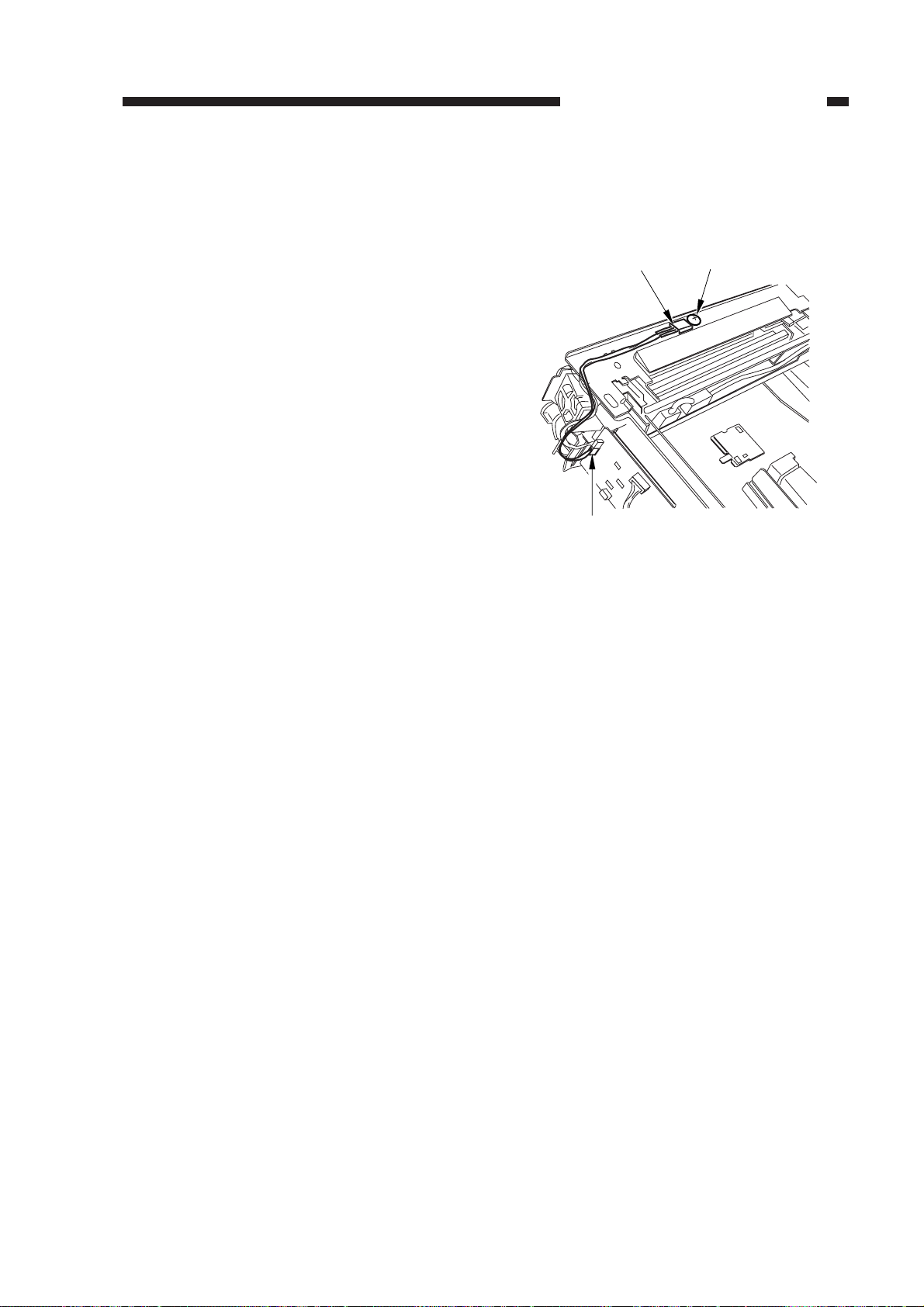
5. Removing the Thermistor Unit
1) Remove the top cover.
(See Chapter 7.III.A.1. “Removing the
Top Cover.”)
2) Disconnect the connector (J131) [1] from
the DC controller PCB; remove the screw
[2], and detach the thermistor unit [3].
CHAPTER 3 EXPOSURE SYSTEM
[3]
[1]
[2]
Figure 3-353
COPYRIGHT © 1999 CANON INC. CANON PC800s/900s REV.0 AUG. 1999 PRINTED IN JAPAN (IMPRIME AU JAPON)
3-41
Page 92

Page 93

CHAPTER 4
IMAGE FORMATION SYSTEM
This chapter discusses the principles of how images are formed. It also explains the
timing at which the various units involved in image formation are operated, and shows
how they may be disassembled/assembled and adjusted.
I. IMAGE FORMATION SYSTEM ...4-1
A. Outline ...................................4-1
B. Timing Chart for the Image
Formation System .................4-3
C. Controlling the Pr imar y
Charging Roller Bias .............4-4
D. Controlling the Transfer
Roller Bias.............................4-8
E. Controlling the Developing/
Separation Static Eliminator
Bias .................................... 4-11
COPYRIGHT © 1999 CANON INC. CANON PC800s/900s REV.0 AU G. 1999 PRINTED IN JAPAN (IMPRIME AU JAPON)
F. Measuring the Density of
Originals ............................. 4-16
G. Controlling the Side Blanking
Mechanism......................... 4-21
II. DISASSEMBLY/ASSEMBLY ..... 4-22
A. Cartridge ............................ 4-23
B. Transfer Charging
Assembly............................ 4-25
C. Blank Exposure .................. 4-26
Page 94

Page 95

CHAPTER 4 IMAGE FORMATION SYSTEM
I. IMAGE FORMATION SYSTEM
A. Outline
The major functions of the image formation system are as follows:
Item
Controlling the primary charging
roller bias
Transfer roller bias control
Developing/separation static
eliminator bias control
Density control
Blanking control
Description
AC constant current control, on/off control
DC constant voltage control, on/off control
DC voltage level control
DC constant voltage control, on/off control
DC constant current control (ATVC, cleaning bias)
Voltage level control
Polarity switching
DC constant voltage control, on/off control
AC constant voltage control, on/off control
DC voltage level control
Developing DC bias control
Side blanking lamp
Table 4-101
COPYRIGHT © 1999 CANON INC. CANON PC800s/900s REV.0 AUG. 1999 PRINTED IN JAPAN (IMPRIME AU JAPON)
4-1
Page 96
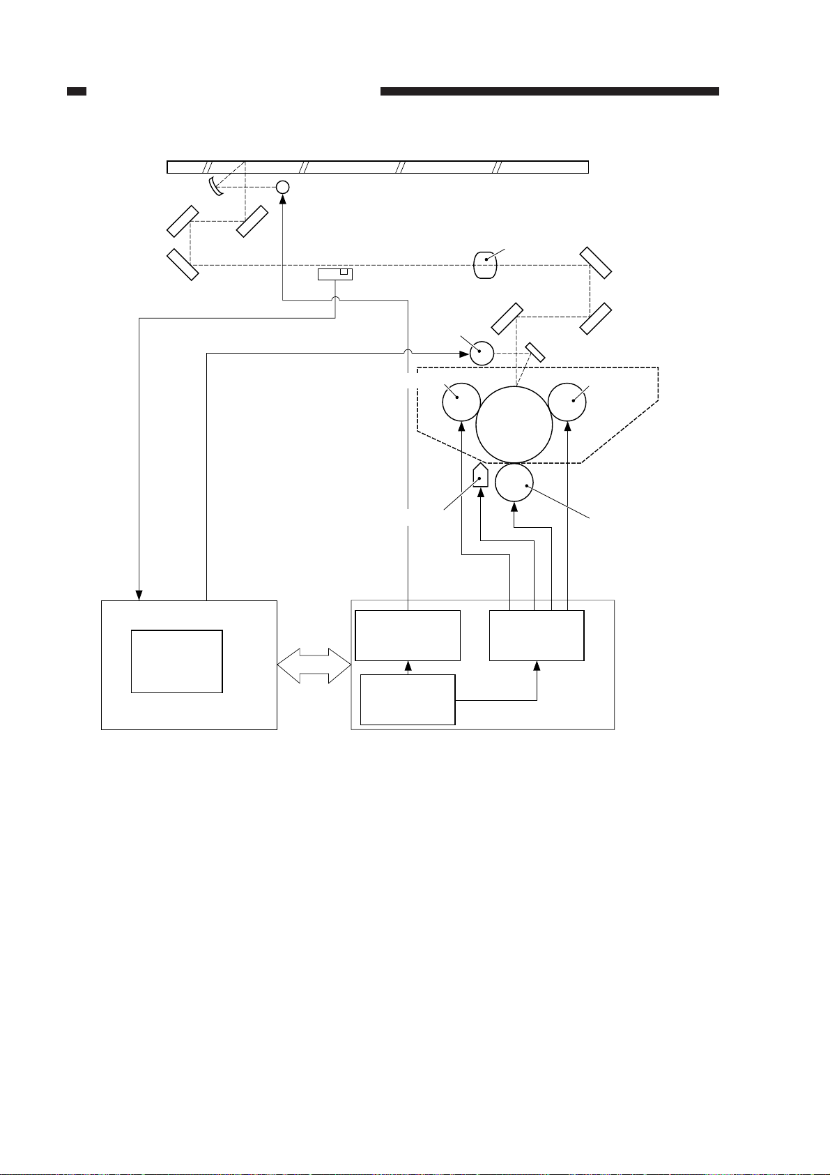
CHAPTER 4 IMAGE FORMATION SYSTEM
Copyboard glass
Scanning lamp
AE sensor
Lens
Side
blanking
lamp
Q101
Microprocessor
DC controller PCB
Primary charging roller
Static eliminator
Lamp regulator
block
Q900
Microprocessor
Figure 4-101
Developing cylinder
Photo-
sensitive
drum
Drum cartridge
Transfer roller
High-voltage
circuit block
Composite power supply
PCB
4-2
COPYRIGHT © 1999 CANON INC. CANON PC800s/900s REV.0 AUG. 1999 PRINTED IN JAPAN (IMPRIME AU JAPON)
Page 97
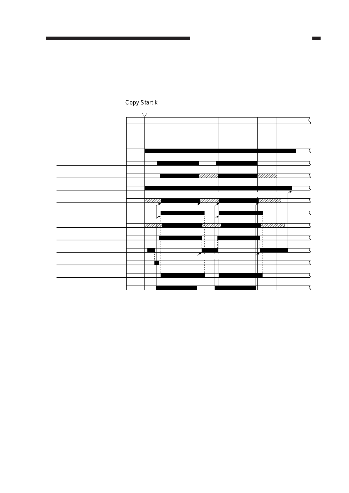
CHAPTER 4 IMAGE FORMATION SYSTEM
B. Timing Chart for the Image Formation System
Basic Sequence of Operations (Direct, 2 copies, continuous)
Copy Start key
ON
Main motor (M1)
Scanning lamp (LA1)
Scanner
Primary AC bias
Primary DC bias
Developing AC bias
Developing DC bias
Transfer bias
Transfer cleaning bias
Transfer reference
bias (ATVC)
Static eliminator bias
Pre-registration roller
paper sensor (Q751)
STBY
INTR
-400V
-500V
SCFW
forward
-625V
3200V
SCFWSCRV
Reverse
0.5sec.(approx.)
0.6sec.(approx.)
SCRV
0.6sec.(approx.)
LSTR
STBY
Figure 4-102
COPYRIGHT © 1999 CANON INC. CANON PC800s/900s REV.0 AUG. 1999 PRINTED IN JAPAN (IMPRIME AU JAPON)
4-3
Page 98

CHAPTER 4 IMAGE FORMATION SYSTEM
C. Controlling the Primary Charging Roller Bias
1. Outline
The circuit shown in Figure 4-103 is used to control the voltage applied to the primary charging
roller, and has the following functions:
• Turning on and off the DC/AC bias
• Controlling the DC bias to a specific voltage
• Controlling the AC bias to a specific voltage
• Switching the level of the DC bias
Both DC bias and AC bias are applied to the primary charging roller so as to ensure that the
surface potential of the photosensitive drum will be uniform. The level of the DC bias is switched
between when forming copy images and when not forming copy images.
Reference:
DC component: -400 V (non-image area)/-625 V (image area)
AC component: 2000 Vpp to 3000 Vpp (885µA)
4-4
COPYRIGHT © 1999 CANON INC. CANON PC800s/900s REV.0 AUG. 1999 PRINTED IN JAPAN (IMPRIME AU JAPON)
Page 99
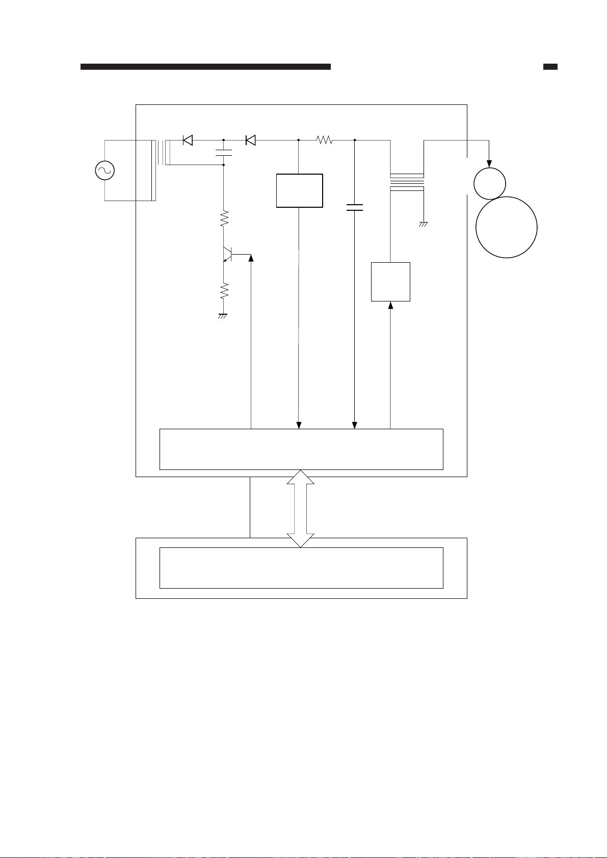
Main
transformer
CHAPTER 4 IMAGE FORMATION SYSTEM
T101
Voltage
separation
circuit
PDC_PWM
DC bias control signal
Microprocessor (Q900)
PDC_S
DC voltage monitor signal
High-voltage
T508
Amplifier
PAC_S
AC component current monitor signal
AC bias output signal
transformer
for primary
charging
Photosensitive
PAC_OUT
Primary
charging
roller
drum
-5
J203
PR_DC_ON
J103
-4
Microprocessor (Q101)
Figure 4-103
Composite power supply PCB
Serial communication
DC controller PCB
COPYRIGHT © 1999 CANON INC. CANON PC800s/900s REV.0 AUG. 1999 PRINTED IN JAPAN (IMPRIME AU JAPON)
4-5
Page 100

CHAPTER 4 IMAGE FORMATION SYSTEM
2. Operations
a. Turning On and Off the DC Bias
The DC bias applied to the primary charging roller is turned on or off by the serial communication signal and the primary charging bias ON signal (PR_DC_ON) from the DC controller PCB.
When the Copy Start key is pressed, the DC bias ON signal (serial) and the primary charging
bias ON signal (PR_DC_ON) are sent. The microprocessor (Q900) on the composite power supply
PCB generates the DC bias control signal (PDC_PWM) based on the combination of the serial
signal and the PR_DC_ON signal, applying a DC bias to the primary charging roller.
PR_DC_ON
(J103-4)
0
1
1
DC bias ON
(image area)
DC bias ON
(non-image area)
DC bias OFF
DC bias ON signal
(8-bit signal communication)
bit0 bit1
1–
10
00
Table 4-102 Relationship between DC Bias Output and Signal
b. Turning On and Off the AC Bias
The AC bias applied to the primary charging roller is turned on and off by the serial communication signal from the DC controller PCB.
When the AC bias ON signal arrives from the DC controller PCB, the microprocessor (Q900)
on the composite power supply PCB generates the AC bias output signal (PAC_OUT), thereby
applying an AC bias to the primary charging roller.
c. Controlling the DC/AC Bias to a Specific Voltage/Current
The DC bias and the AC bias applied to the primary charging roller are controlled by the
microprocessor (Q900) on the composite power supply PCB so that they remain a specific level.
When a DC/AC bias is generated, the microprocessor (Q900) on the composite power supply
PCB detects the DC voltage monitor signal (PDC_S) and the AC component current monitor signal
(PAC_S), compares their levels against the reference levels, and varies the DC bias control signal
(PDC_PWM) and the AC bias output signal (PAC_OUT) according to the differences so as to
ensure that they remain specific levels.
Reference:
The DC bias control signal varies its pulse duty ratio while the AC bias output signal varies its
amplitude to change the level of the DC/AC bias.
4-6
COPYRIGHT © 1999 CANON INC. CANON PC800s/900s REV.0 AUG. 1999 PRINTED IN JAPAN (IMPRIME AU JAPON)
 Loading...