

Page 1
ZR10A
CHAPTER 4. DISASSEMBLING ADJUSTMENT
1. Disassembling and Reassembling
Notes :
(1) When replacing the flat cable with a new one, allow it to remain folded the same as the original part.
(2) The contact orientation for how the flat cable engages with the counter is specified. Refer to the instructions in the
disassembly procedure diagram and interconnection diagram for the boards.
• Lateral engaging connector
(The instructions are given in the disassembly procedure diagram and board interconnection diagram.)
: Contacts are positioned downward. (board side)
* : Contacts are positioned upward.
• Lengthwise engaging connector
(The instructions are given only in the board interconnection diagram.)
Indicated by →. Arrowheads indicate contacts, then shafts indicate noncontacts.
(3) To secure screws, apply Three Bond 1401B (CY9-8012-000)
(4) When UL tape is applied on the original part that is to be replaced, apply the tape after replacement.
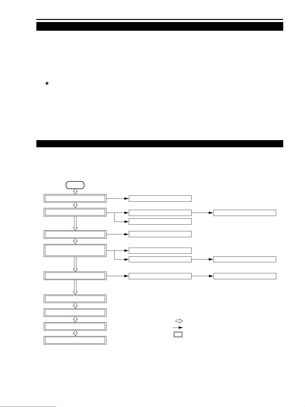
1-1 General Disassembling / Reassembling Flowchart
(1) Find the replacement part on the chart, then disassemble it following the instructions on the chart.
(2) Reassemble by reversing the disassembling procedures.
START
FRONT COVER UNIT (P.4-4)
R COVER UNIT (P.4-5)
L COVER UNIT (P.4-5)
REAR COVER UNIT
CVF UNIT (P.4-6)
CAMERA UNIT (P.4-7)
PMCA P.C.B. (P.4-7)
MAIN P.C.B. (P.4-8)
RECORDER HOLDER (P.4-8)
DMC
MIC UNIT (P.4-9)
LCD UNIT (01) (P.4-9)
R COVER UNIT (small part) (P.4-11)
L COVER UNIT (small part) (P.4-12)
REAR COVER UNIT (small part) (P.4-13)
CVF UNIT (01) (P.4-14)
CCD ASS'Y (P.4-15)
: MAIN FLOW
: SUB FLOW
: MAIN UNIT
LCD UNIT (02) (P.4-10)
CVF UNIT (02) (P.4-15)
LENS UNIT (P.4-16)
4-3
Page 2
ZR10A
CHAPTER 4. DISASSEMBLING ADJUSTMENT
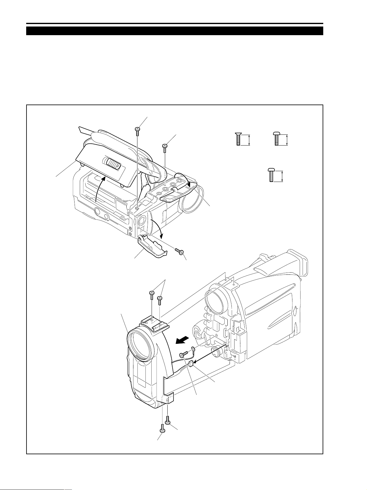
1-2 Front Cover Unit
(1) Open the AV Cover and remove the screw (b × 1).
(2) Open the Jack Cover and remove the screw (b × 1).
(3) Open the Cassette Cover and remove the screw (b × 1).
(4) Remove the five screws (a × 2, b × 2, d × 1).
(5) Remove CN701 and remove the Front Cover.
<Note on assembling>
(1) Route the MIC Cable under the R Cover.
(3)-b
Cassette Cover
(3)
Jack Cover
(2)
(4)-a
(1)-b
(1)
(2)-b
AV Cover
ab
4.0mm 3.0mm
METAL
M1.7
METAL
M1.7
d
4.5mm
METAL
M1.7
(SELF TAP)
Front Cover Unit
(5)
CN701
(4)-b
(4)-d
(4)-b
Fig. 4-1
4-4
Page 3
CHAPTER 4. DISASSEMBLING ADJUSTMENT
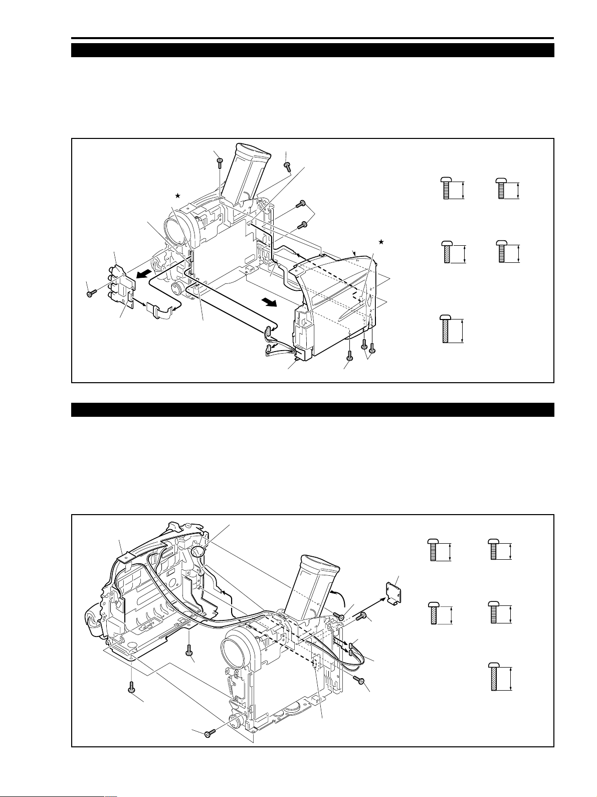
1-3 R Cover Unit
(1) Remove the seven screws (b × 1, r × 1, j × 2, e × 1, f × 2).
(2) Remove CN1502, CN3202, CN102 and CN150, then remove the R cover.
(3) Remove the screw (b × 1), CN01, CN801 and remove the JACK P.C.B..
<Note on assembling>
(1) Route the LCD Cable under the R Cover.
(1)-e
CN801
CN1502
(1)-b
CN102
(1)-j
b
METAL
M1.7
3.0mm
ZR10A
r
4.0mm
BLACK
M1.7
JACK P.C.B.
(3)-b
CN01
(3)
(3)
CN3202
(2)
(2)
(2)
(2)
(2)
R Cover Unit
CN150
(1)-f
(1)-r
Fig. 4-2
1-4 L Cover Unit
(1) Remove the four screws (b × 2, j × 1, r × 1).
(2) Lift up the CVF Unit and remove the screw (f × 1).
(3) Remove the LI BATT Cover and remove the screw (c × 1).
(4) Remove CN252, CN253 and CN254 and remove the L Cover.
<Note on assembling>
(1) Route the cords of CN252 and CN253 under the Rear Cover of the CVF Unit.
α :
When assembling, let portion α of the Power Key
L Cover Unit
ASS'Y Flexible Board face upward so that it is not
pinched by LI P.C.B.
j
BLACK
M1.7
(SELF TAP)
f
BLACK
M1.7
(SELF TAP)
b
3.0mm
4.5mm
6.0mm
e
4.0mm
METAL
M1.7
c
2.5mm
(1)-b
(1)-b
(1)-r
(4)
CN254 *
Fig. 4-3
4-5
(2)
(4)
(4)
(2)-f
CN252
LI BATT Cover
(3)
(3)-c
CN253
(1)-j
METAL
M1.7
j
BLACK
M1.7
(SELF TAP)
4.5mm
METAL
M1.7
r
4.0mm
BLACK
M1.7
f
6.0mm
BLACK
M1.7
(SELF TAP)
Page 4
ZR10A
(1)
CHAPTER 4. DISASSEMBLING ADJUSTMENT
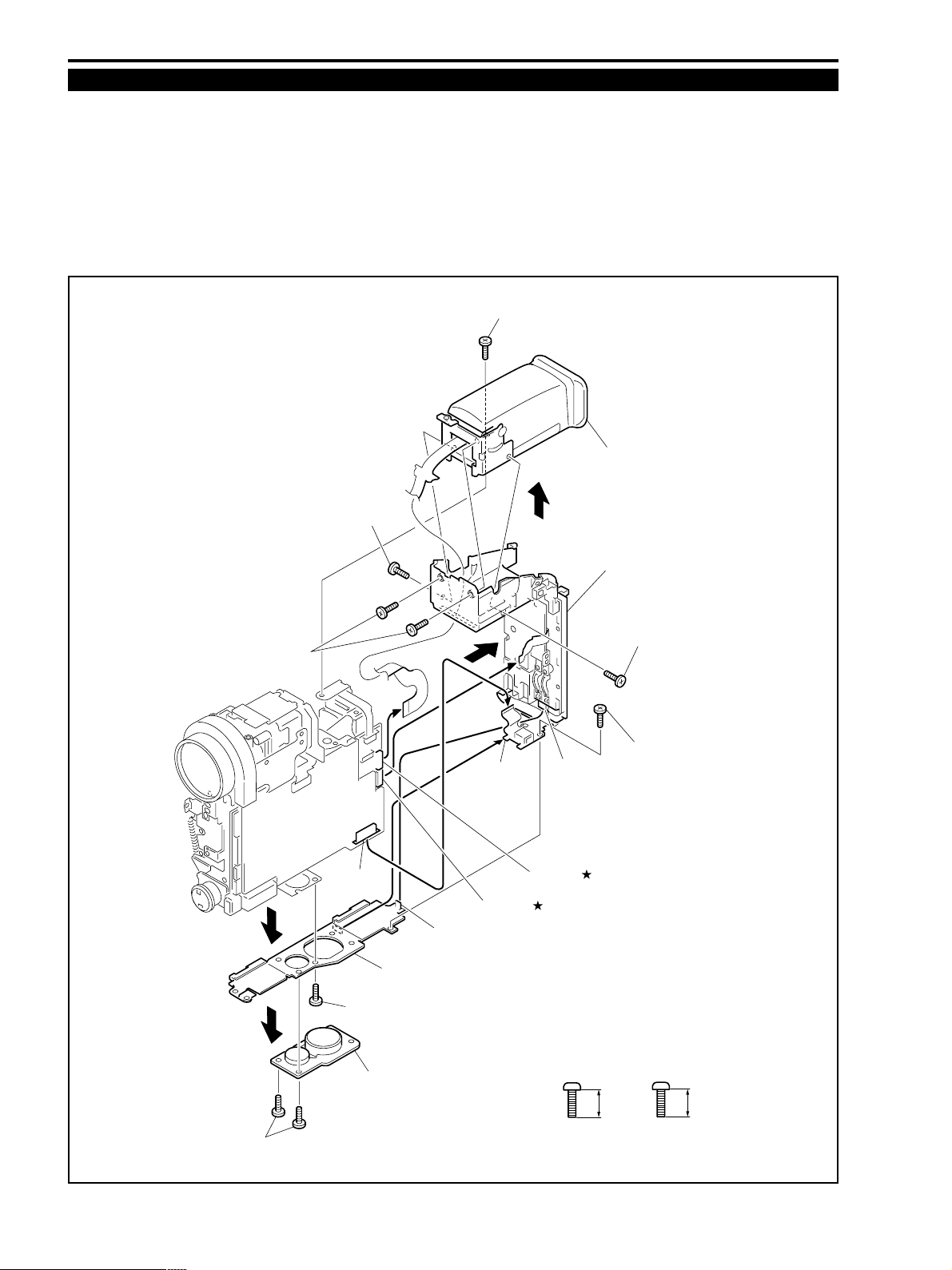
1-5 Rear Cover and CVF Unit
(1) Remove the two screws (b × 2), then remove the TRIPOD Socket.
(2) Remove the screw (b × 1), then remove the C Lock Holder.
(3) Remove CN3201 and screw (h × 1), then remove the claw of BATT FPC from the C Lock Holder.
(4) Remove the claw of the C Lock Holder from the Rear Cover Unit.
(5) Remove the screw (b × 1) that secures CN1201, CN1501, the CVF Hinge Block and the Recorder Holder and remove
the Rear Cover Unit.
(6) Remove the four screws (b × 4), then remove the CVF Unit.
(5)-b
CVF Unit
(6)
(2)
(6)-b
(6)-b
* CN3201
(5)
Claw
C Lock Holder
(5)
(5)
(3)
Claw
CN1201
(3)
Rear Cover Unit
(6)-b
(3)-h
(4)
CN1501
(1)
-b
(2)-b
TRIPOD Socket
Fig. 4-4
4-6
b
METAL
M1.7
3.0mm
h
2.0mm
METAL
M1.7
Page 5
CHAPTER 4. DISASSEMBLING ADJUSTMENT
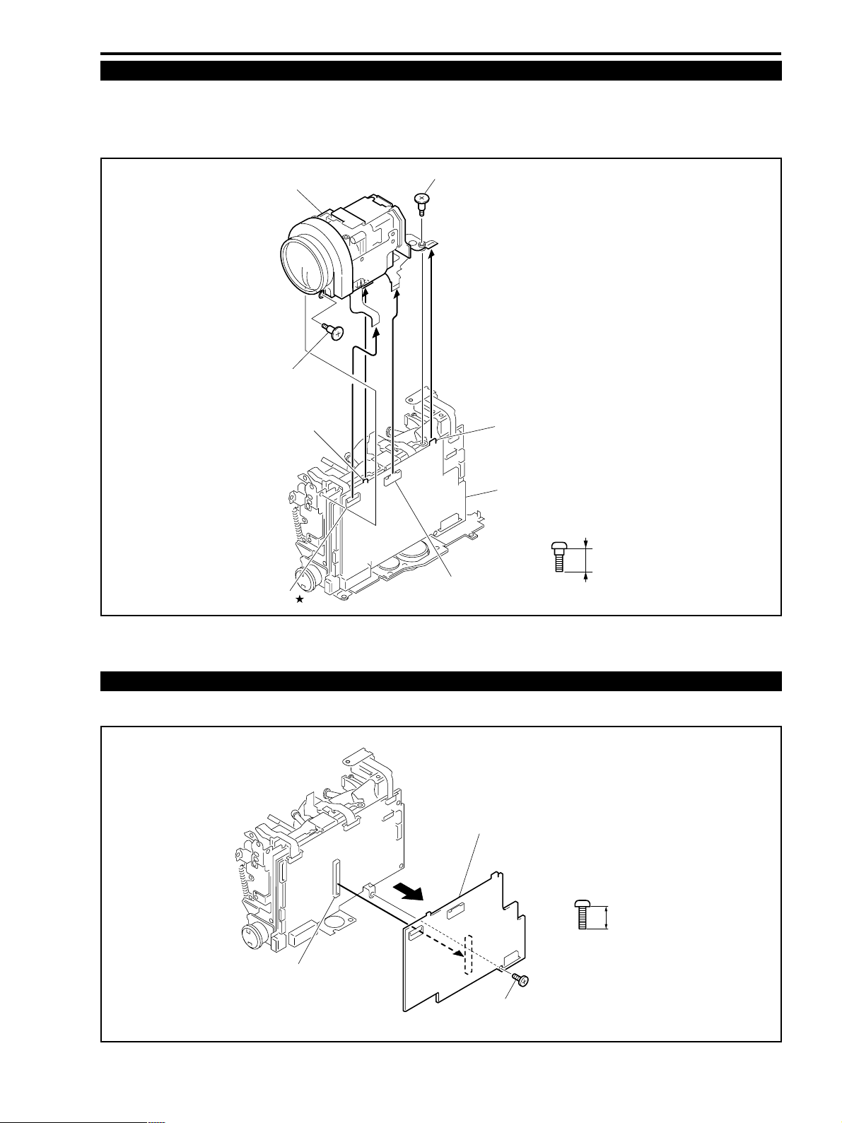
1-6 Camera Unit
(1) Remove the two screws (i × 2).
(2) Remove CN1300 and CN1001.
(3) Remove the Camera Unit by lifting up it from the two claws of the PMCA P.C.B..
ZR10A
Camera Unit
(1)-i
Claw
(1)-i
(2)
(2)
Claw
PMCA P.C.B.
i
3.4mm
CN1300
CN1001 *
Fig. 4-5
1-7 PMCA P.C.B.
(1) Remove the screw (c × 1) and CN1400, then remove the PMCA P.C.B..
PMCA P.C.B.
(1)
CN1400
METAL
M1.4
c
2.5mm
METAL
M1.7
Fig. 4-6
4-7
(1)-c
Page 6
ZR10A
CHAPTER 4. DISASSEMBLING ADJUSTMENT
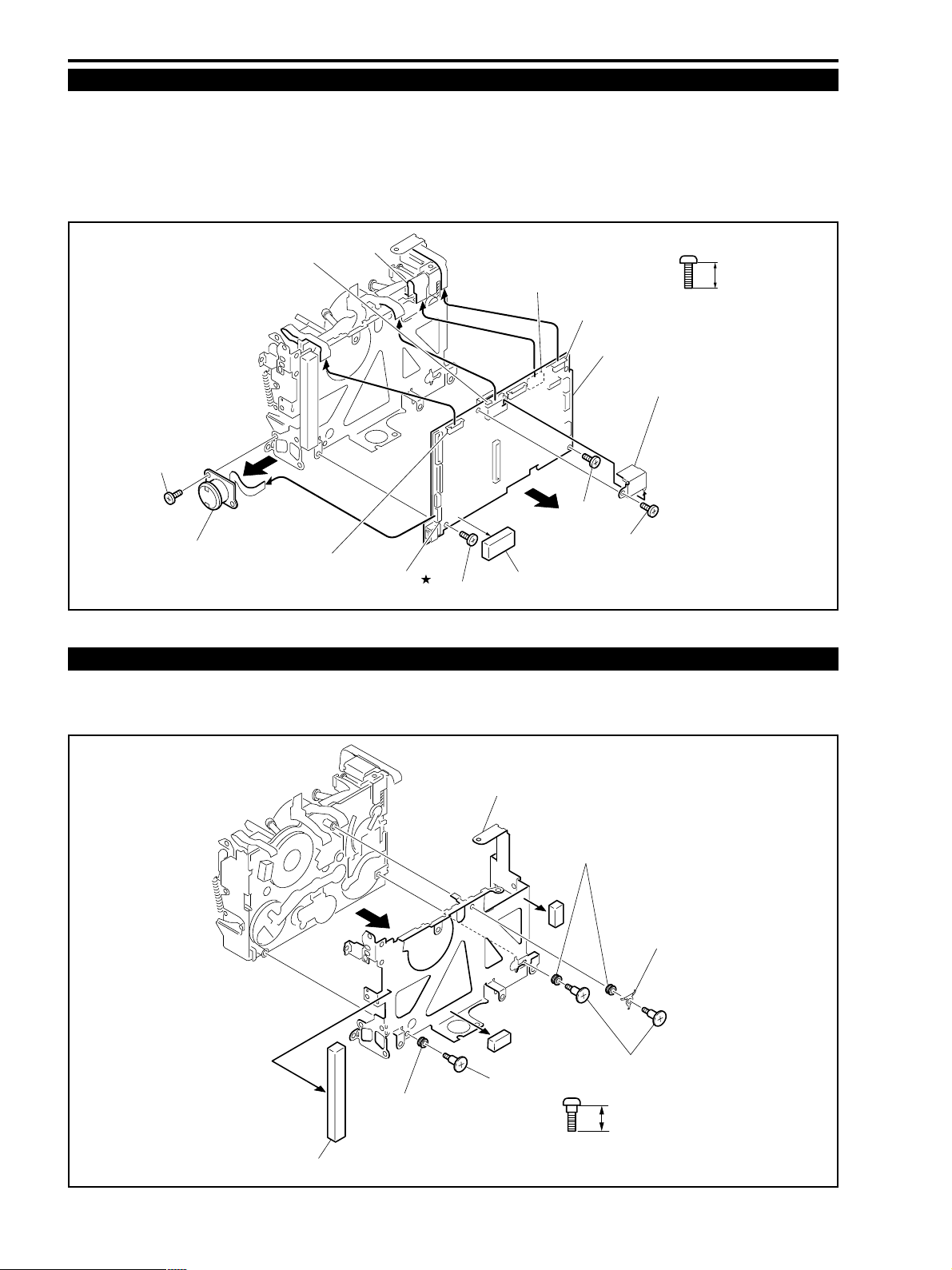
1-8 MAIN P.C.B.
(1) Remove the screw (c × 1), remove CN2103, then remove the SJ P.C.B..
(2) Remove the Rubber and the Shield HA F Case, then remove the three screws (c × 3).
(3) Remove CN1300, CN2000, CN1302 and CN303, then remove the MAIN P.C.B..
Note) Be sure to remove the Flexible Board connected to CN303 at the MAIN P.C.B. side. (connector protec-
tion at the DMC II side)
(1)-c
SJ P.C.B.
(1)
CN2000 *
(1)
CN1300 *
(3)
Note)
(3)
CN2103
(3)
(3)
(2)-c
(2)
CN303
CN1302 *
MAIN P.C.B.
Shield HA F Case
(3)
(2)-c
(2)-c
Rubber
c
2.5mm
METAL
M1.7
Fig. 4-7
1-9 Recorder Holder
(1) Remove the Rubber.
(2) Remove the three screws (i × 3), three Rubbers and the Plate Spring, then remove the Recorder Holder.
(1)
Rubber
(2)
Rubbers
Recorder Holder
Fig. 4-8
4-8
(1)
(2)-i
Rubbers
(1)
Plate Spring
(2)-i
i
3.4mm
METAL
M1.4
Page 7
CHAPTER 4. DISASSEMBLING ADJUSTMENT
(
)
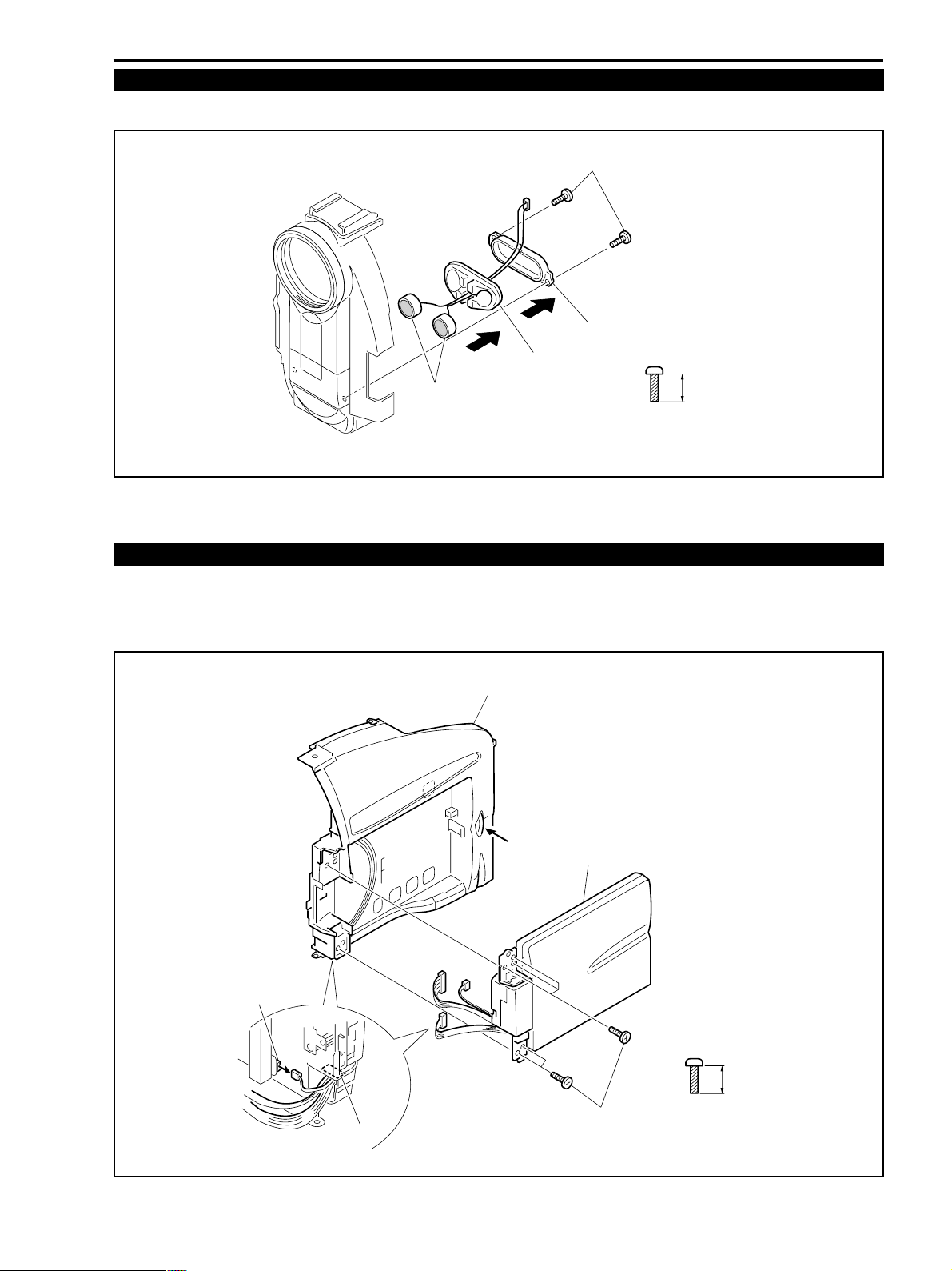
1-10 MIC Unit
(1) Remove the two screws (k × 2), then remove the MIC Holder, the MIC Rubber and the MIC ASS’Ys.
(1)-k
(1)
MIC Holder
MIC ASS'Ys
(1)
MIC Rubber
k
5.0mm
METAL
M1.7
SELF TAP
ZR10A
Fig. 4-9
1-11 LCD Unit (01)
(1) Remove the five screws (d × 5) and CN1, then remove the LCD Unit.
<Note on assembling>
(1) Route the three cords coming from the LCD Unit under the hole of the R Cover Unit.
R Cover Unit
LCD Unit
CN1
Hole
d
4.5mm
(1)-d
METAL
M1.7
(SELF TAP)
Fig. 4-10
4-9
Page 8
ZR10A
CHAPTER 4. DISASSEMBLING ADJUSTMENT
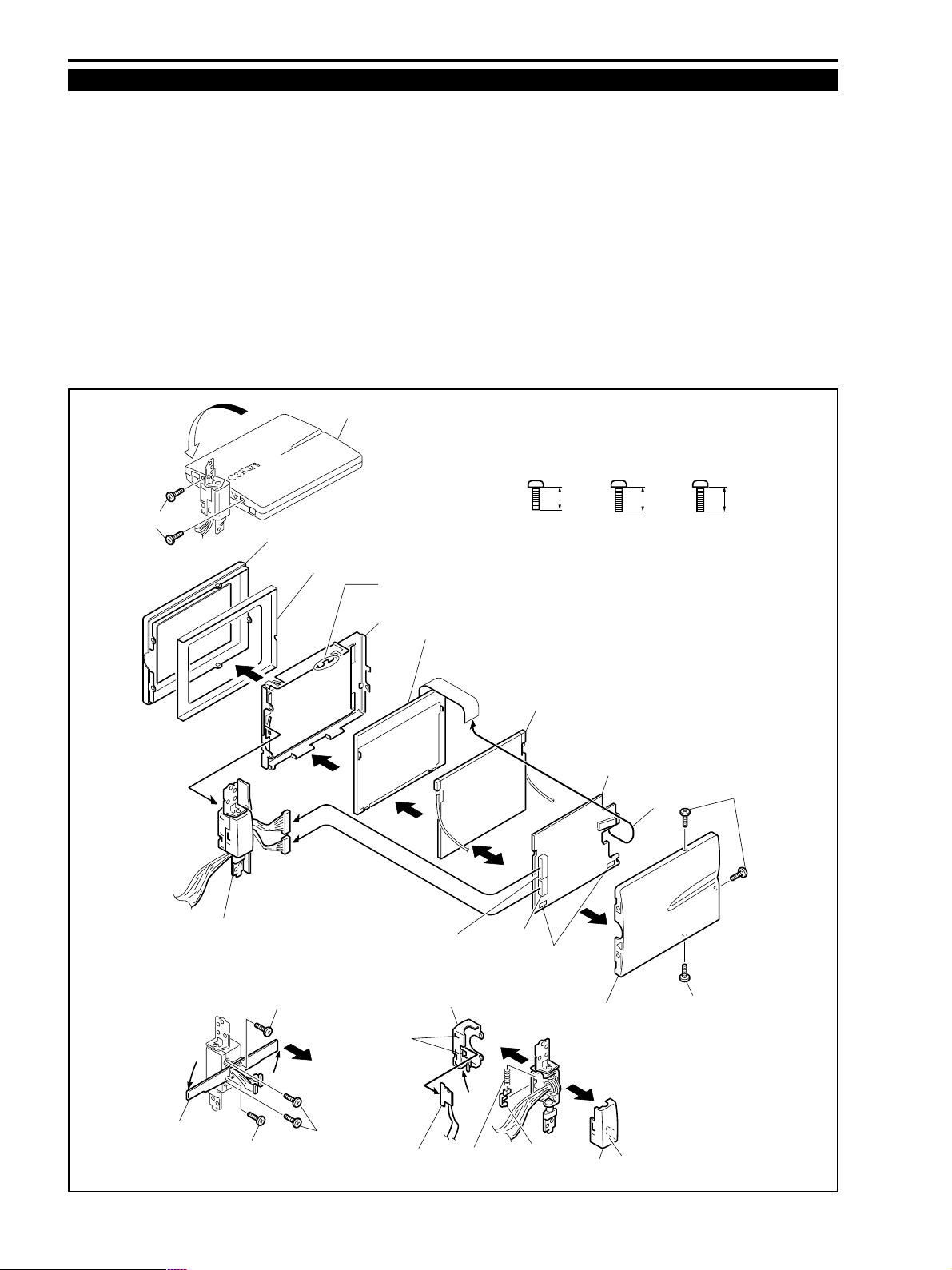
1-12 LCD Unit (02)
(1) Rotate the LCD by 90° and remove the two screws (e × 2).
(2) Remove the three screws (c × 3), then remove the LCD Top Cover ASS’Y.
(3) Remove the LCD Hinge ASS’Y, the LCD B-CD Sheet and the LCD Bottom Cover from the LCD Holder.
(4) Remove CN901 and CN902, then remove the LCD Hinge ASS’Y.
(5) Remove soldering (α), then remove the LCD holder.
(6) Remove CN903 and remove the LCD ASS’Y.
(7) Remove soldering (β), then detach the Back Light ASS’Y and the LCD P.C.B..
(8) Rotate the Hinge LCD Holder by 90° in the direction of the arrow and remove the four screws (c × 2, q × 2).
(9) Detach the Hinge L Cover and the Hinge R Cover, then remove the DSW P.C.B., the Hinge Cover and the Spring.
<Note on assembling>
(1) Route the cord through portion (∂) of the Hinge L and the R Cover.
(2) Confirm from the hole of (ε) that the DSW P.C.B. contacts the Hinge L Cover.
(1)-e
(1)
(3)
LCD Bottom Cover
(3)
(4)
(4)
LCD
LCD B-CD Sheet
(5)-α
LCD Holder
(5)
LCD ASS'Y
(6)
METAL
M1.7
Back Light ASS'Y
(6)
(7)
ceq
2.5mm 4.0mm 3.2mm
METAL
M1.7
LCD P.C.B.
CN903 *
METAL
M2.0
(2)-c
LCD Hinge ASS'Y
Hinge LCD Holder
(8)-c
(8)-c
(8)-q
Hinge L Cover
(ε)
(9)
DSW P.C.B.
Fig. 4-11
CN902
Spring
4-10
(∂)
CN901
(9)
Hinge Lever
(2)
(7)-β
LCD Top Cover ASS'Y
(9)
(∂)
Hinge R Cover
(2)-c
Page 9
CHAPTER 4. DISASSEMBLING ADJUSTMENT
(
)
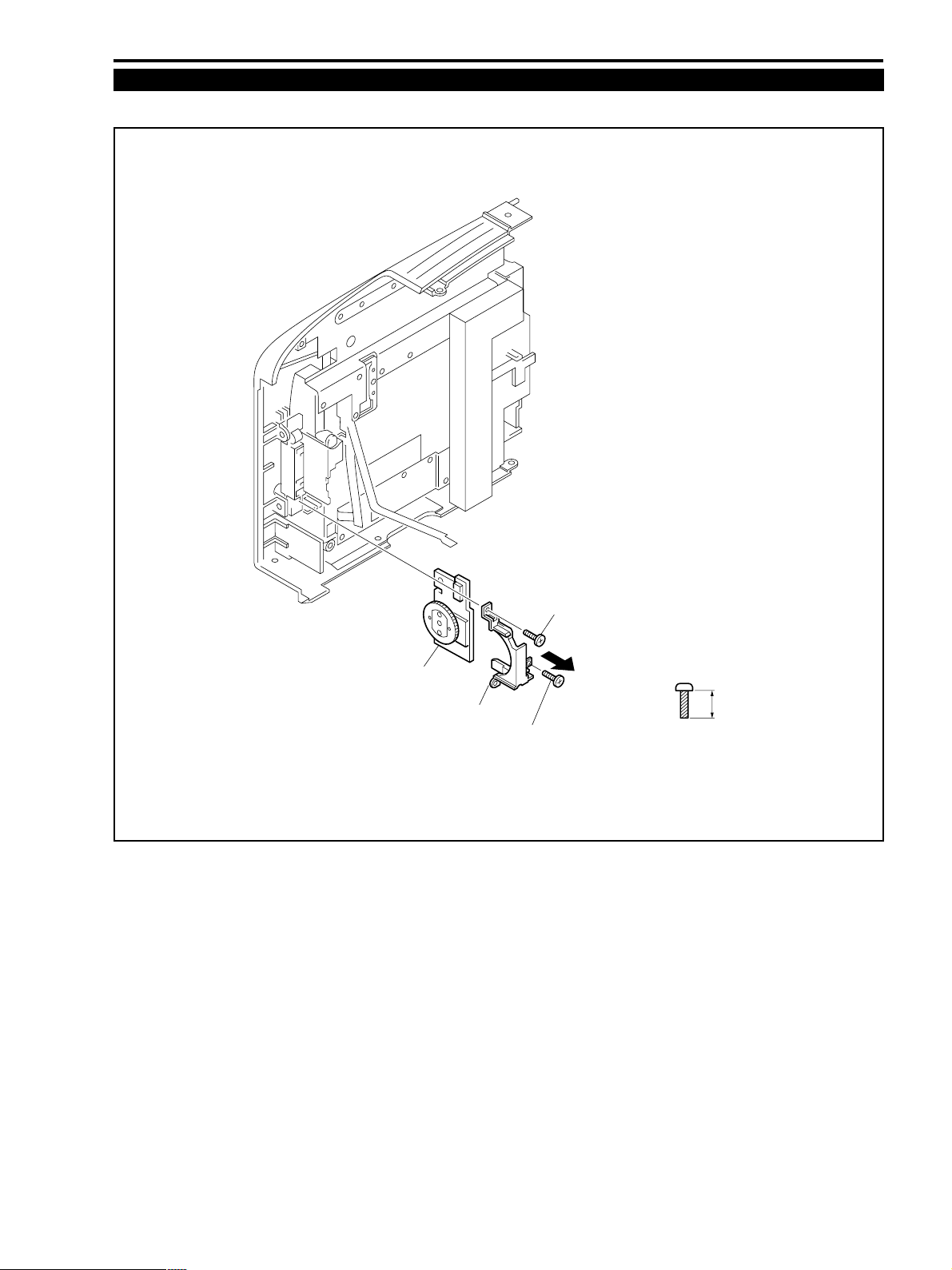
1-13 R Cover Unit (small part)
(1) Remove the two screws (d × 2), then remove the LED Cover and the JOG P.C.B..
ZR10A
JOG P.C.B.
LED Cover
Fig. 4-12
(1)-d
(1)-d
d
4.5mm
METAL
M1.7
SELF TAP
4-11
Page 10
ZR10A
CHAPTER 4. DISASSEMBLING ADJUSTMENT
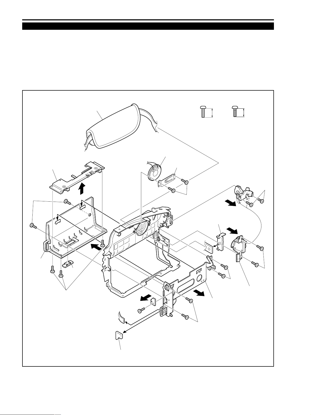
1-14 L Cover Unit (small part)
(1) Remove the two screws (j × 2), then remove the Speaker Holder and the Speaker.
(2) Remove the four screws (j × 4), then remove the Power Key ASS’Y.
(3) Remove the Grip Stopper, then remove the Hand Strap.
(4) Remove the two screws (c × 2), then remove the Cassette Cover.
(Then, remove the claw of the Cassette Cover from the Cassette Arm ASS’Y.)
(5) Remove the three screws (c × 3), then remove the Cassette Lock ASS’Y and the Open Knob.
(6) Remove the Rubber and the four screws (j × 4), then remove the Cassette Arm ASS’Y.
Cassette Lock ASS'Y
(4)-c
Cassette
Cover
(4)
(4)
Open
Knob
Hand Strap
(5)
(4)
Speaker
Speaker Holder
(1)-j
j
BLACK
M1.7
(SELF TAP)
Grip Stopper
(3)
4.5mm
c
2.5mm
METAL
M1.7
(2)-j
(2)-j
(6)-j
(5)-c
Power Key ASS'Y
Cassette Arm ASS'Y
(3)
(6)-j
(6)
Rubber
Fig. 4-13
4-12
Page 11
ZR10A
(
)
(
)
(
)
CHAPTER 4. DISASSEMBLING ADJUSTMENT
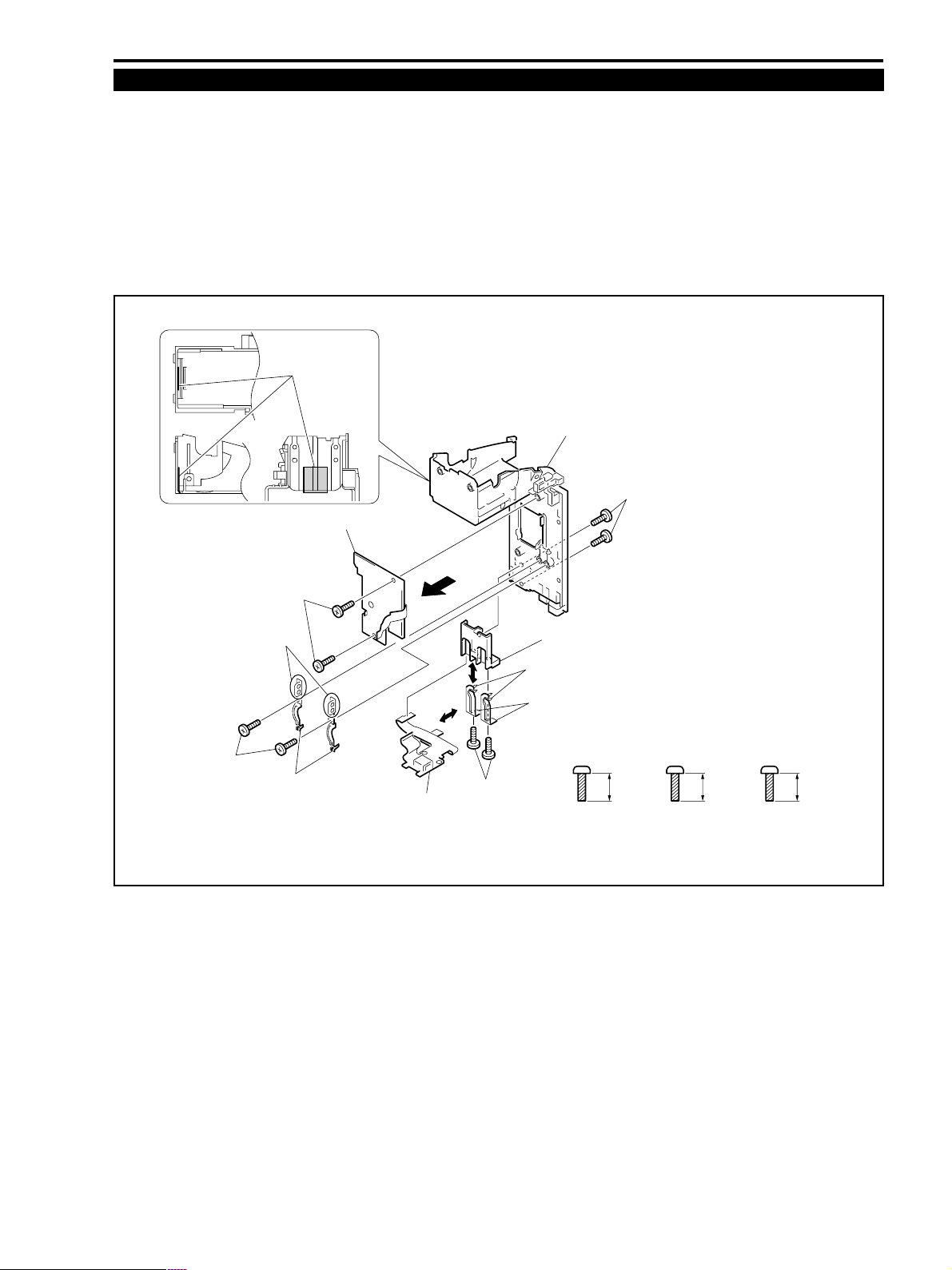
1-15 Rear Cover Unit (small part)
(1) Remove soldering (α) of the LI P.C.B. and the battery terminal, remove the two screws (j × 2), then remove the LI
P.C.B..
(2) Remove the two screws (l × 2), then remove the Battery D terminals.
(3) Remove the two screws (j × 2), then remove the Rear Cover ASS’Y.
(4) Remove the two screws (m × 2), remove soldering (β), then detach the Terminal Holder, Terminal Batteries and
BATT FPC.
<Supply>
A Rear Cover Block : HANARL KS-50 (DY9-3047-000)
Grease coating
position
A
Rear Cover ASS'Y
(2)-j
(2)-l
LI P.C.B.
(1)-j
(1)-α
Battery D terminals
(4)
BATT FPC
(4)
(4)-m
Fig. 4-14
Terminal Holder
Terminal Batteries
(4)-β
j
4.5mm
BLACK
M1.7
SELF TAP
l
METAL
M1.7
SELF TAP
3.5mm
m
3.5mm
BLACK
M1.7
SELF TAP
4-13
Page 12
ZR10A
CHAPTER 4. DISASSEMBLING ADJUSTMENT
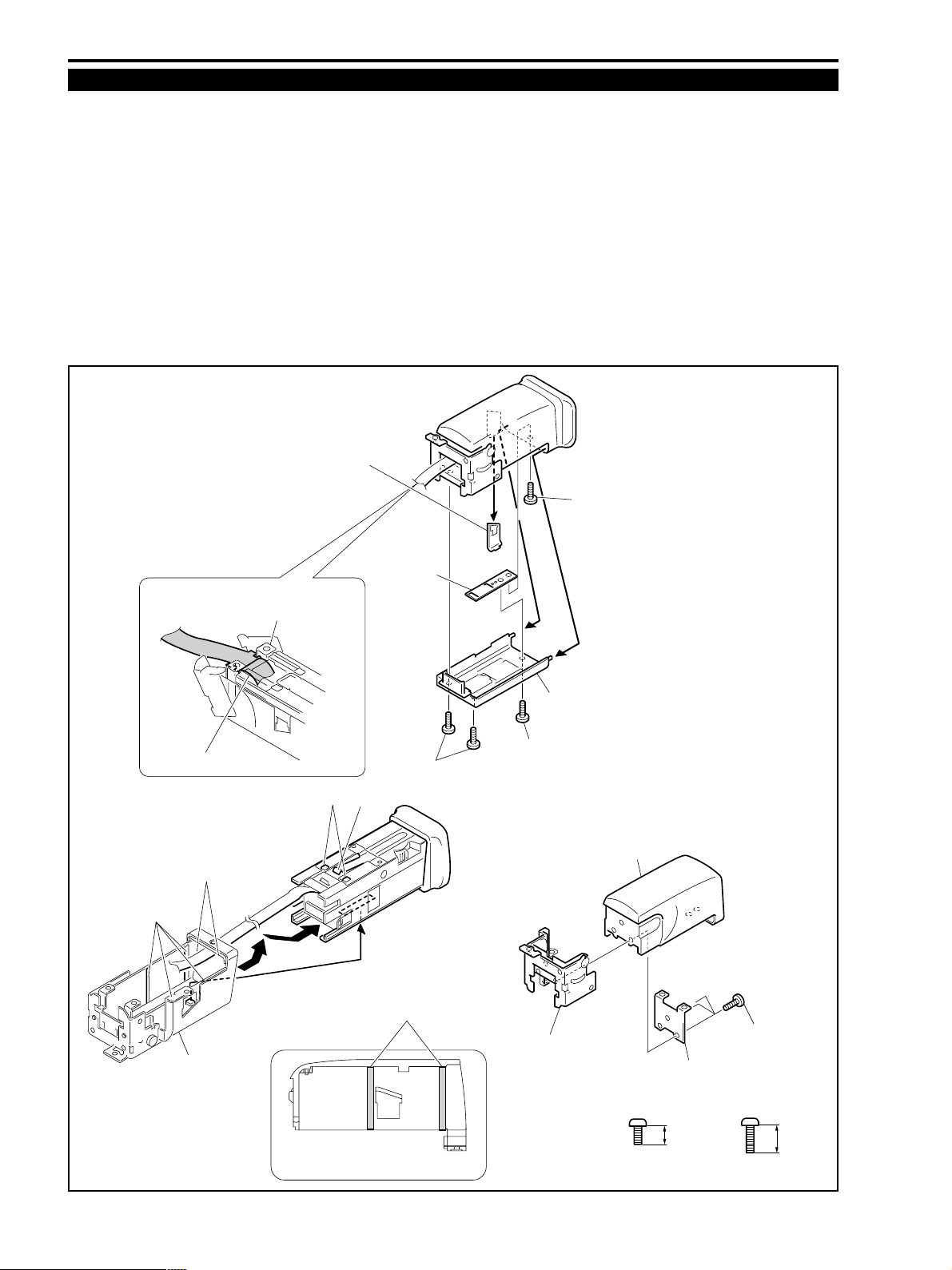
1-16 CVF Unit (01)
(1) Remove the Dust Cover from the side of the CVF Unit.
(2) Remove the four screws (n × 2, h × 2), then remove the CVF Bottom Cover and the CVF Plate in the direction of the
arrows.
(3) When removing the ASS’Y, turn over the CVF Unit, pull out the ASS’Y until it stops, then pull again the ASS’Y over
the projecting portion of the CVF Top Cover in the direction of the bold arrows. (Pull out the ASS’Y by removing the
projecting portion (α) from (β).)
(4) Remove the three screws (n × 3), then remove the CVF Top Holder and the CVF Hinge ASS’Y.
<Note on assembling>
(1) Align the groove of the Flexible Board and the Hinge ASS’Y as shown in the figure.
<Supply>
A CVF Top Cover, Click Spring Block : HANARL KS-50 (DY9-3047-000)
Dust Cover
Note for assembling
Flexible Board
(3)-β
A
Hinge ASS'Y
(3)-α
(3)
CVF Plate
A
(3)
(2)-n
(1)
(2)-h
(2)
(2)
CVF Bottom Cover
(2)-h
CVF Top Cover
CVF Top Cover
A
Grease coating position
Fig. 4-15
4-14
CVF Hinge ASS'Y
CVF Top Holder
h
METAL
M1.7
2.0mm
(4)-n
n
3.5mm
METAL
M1.7
Page 13
ZR10A
CHAPTER 4. DISASSEMBLING ADJUSTMENT
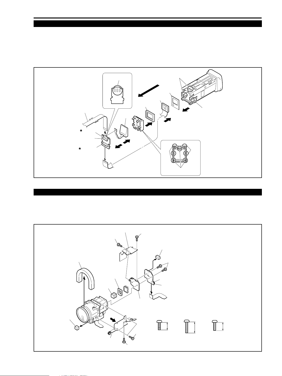
1-17 CVF Unit (02)
(1) Remove CN4101 and remove EVF-MAIN FPC.
(2) Remove the three claws (α), pull out the parts inside the FINDER ASS’Y, remove CN4102, then remove the LCD
ASS’Y.
(3) Remove the four claws (β) and soldering of portion (ε), remove CVF P.C.B.. Remove the three claws (∂), then remove
the Back Light ASS’Y.
(4) Remove the Cushion and the Mask Plate.
(3)
(3)-β
(2)
(2)-α
(3)-∂
(4)
(2)-α
(3)-β
EVF-MAIN FPC
CN4101
CVF P.C.B.
CN4102
(1)
(2)
(3)-ε
Mask Plate
LCD ASS'Y
Cushion
Back Light
ASS'Y
(4)
(3)
(3)
Fig. 4-16
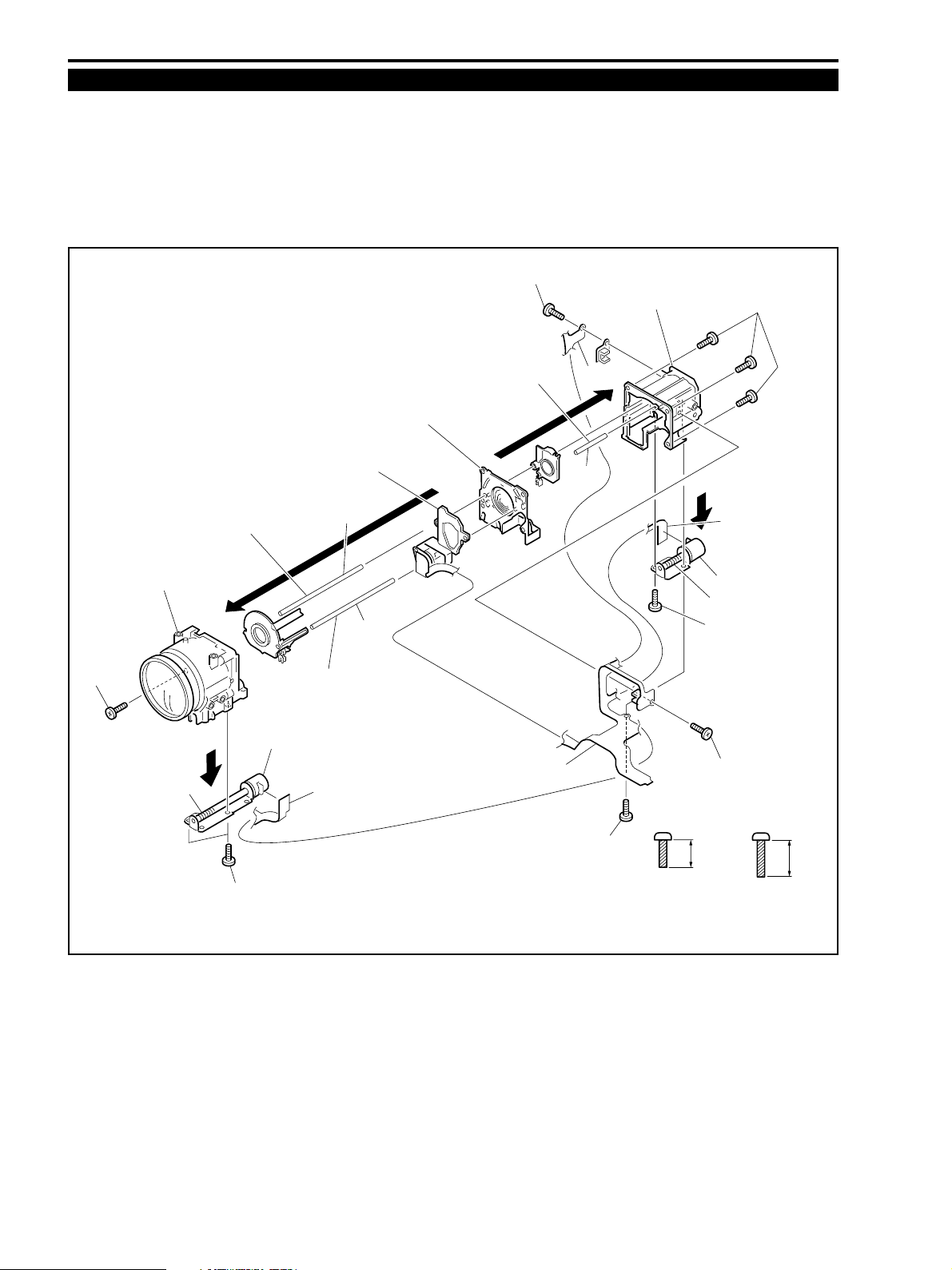
1-18 CCD ASS’Y
(1) Remove the two screws (c × 2), then remove the CCD FIN Plate.
(2) Remove the two screws (m × 3), then remove the Camera Holder.
(3) Remove the two screws (f × 2), then remove the CCD P.C.B., the CCD ASS’Y, the Rubber and the IR Filter.
(4) Remove the Rubbers.
Rubber
Rubber
(4)
(4)
CCD Pin Plate
(1)-c
Rubber
IR Filter
Camera Holder
(1)-c
CCD ASS'Y
(2)-m
(2)-m
Fig. 4-17
4-15
(4)
Rubber
CN1701
c
METAL
M1.7
(3)-f
CCD P.C.B.
2.5mm
(SELF TAP)
f
BLACK
M1.7
6.0mm
m
3.5mm
BLACK
M1.7
(SELF TAP)
Page 14
ZR10A
CHAPTER 4. DISASSEMBLING ADJUSTMENT
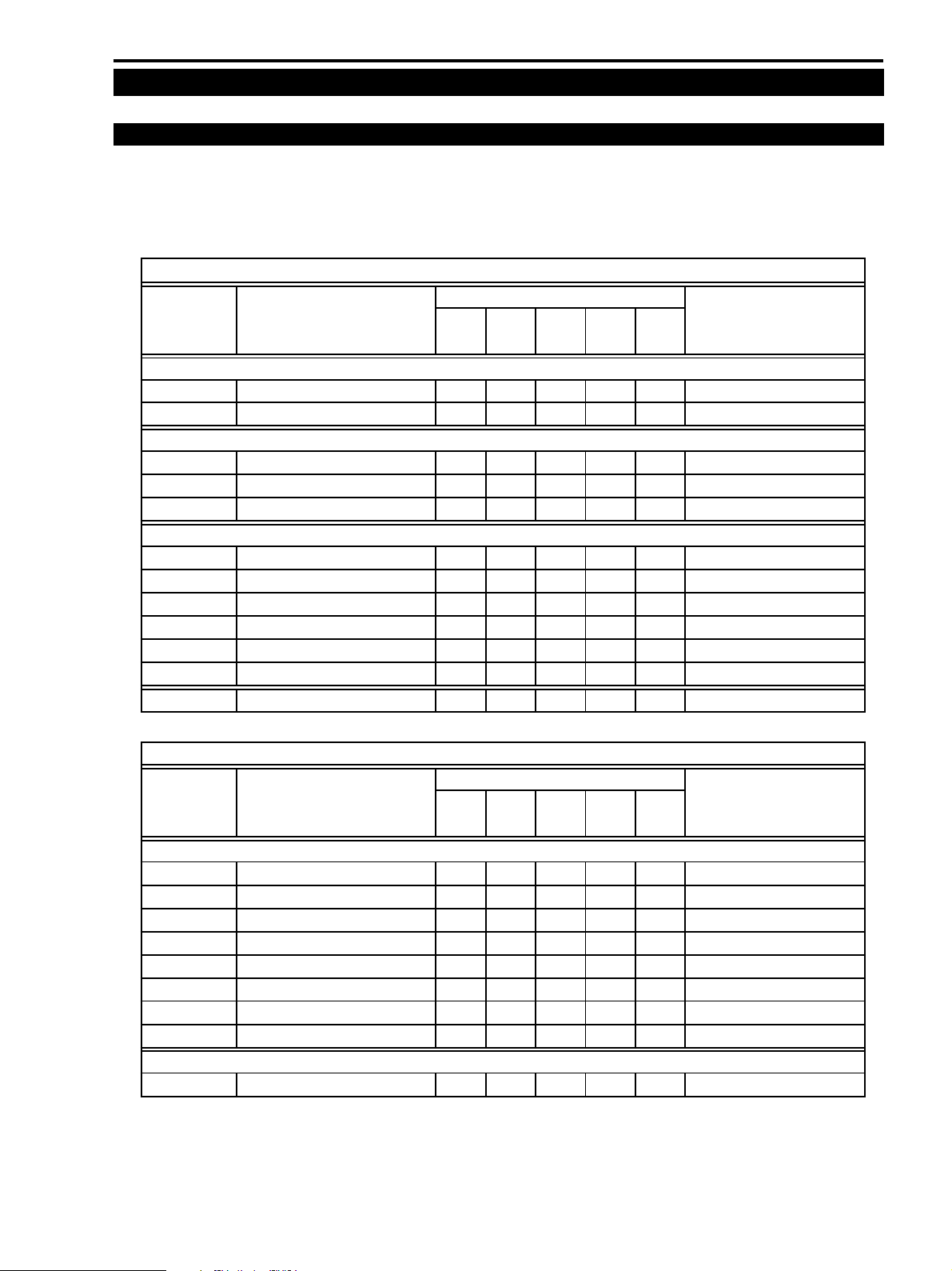
1-19 Lens Unit
(1) Remove the four screws (p × 4), then detach the Front Lens ASS’Y, the Lens ASS’Y, the IG Meter and the Relay Lens
Holder.
(2) Remove the six screws (d × 6) and soldering (α), then remove the PZ Motor, the AF Motor, and the IG Motor ASS’Y.
<Supply>
A AF/PZ Motor Shaft, Guide Bar 1, then 3 : Logenest Lambda A-74 (CY9-8102-000)
B Guide Bar 2 : Mixture of GE-C9 (CY9-8043-000) and GE-X8 (CY9-8044-000) in ratio of 1 : 1
(2)-d
Relay Lens Holder
(1)-p
Front Lens ASS'Y
(1)-p
A
Guide Bar 3
PZ Motor
(2)-d
IG Meter ASS'Y
A
(1)
Guide Bar 2
(2)-α
Lens ASS'Y
B
Guide Bar 1
(1)
IG Meter ASS'Y
(2)-α
A
(2)-d
d
METAL
M1.7
(SELF TAP)
A
(2)-d
(2)-d
4.5mm
(2)-α
AF Motor
p
6.5mm
METAL
M1.7
(SELF TAP)
Fig. 4-18
4-16
Page 15
ZR10A
CHAPTER 4. DISASSEMBLING ADJUSTMENT
2. Adjustment Procedures
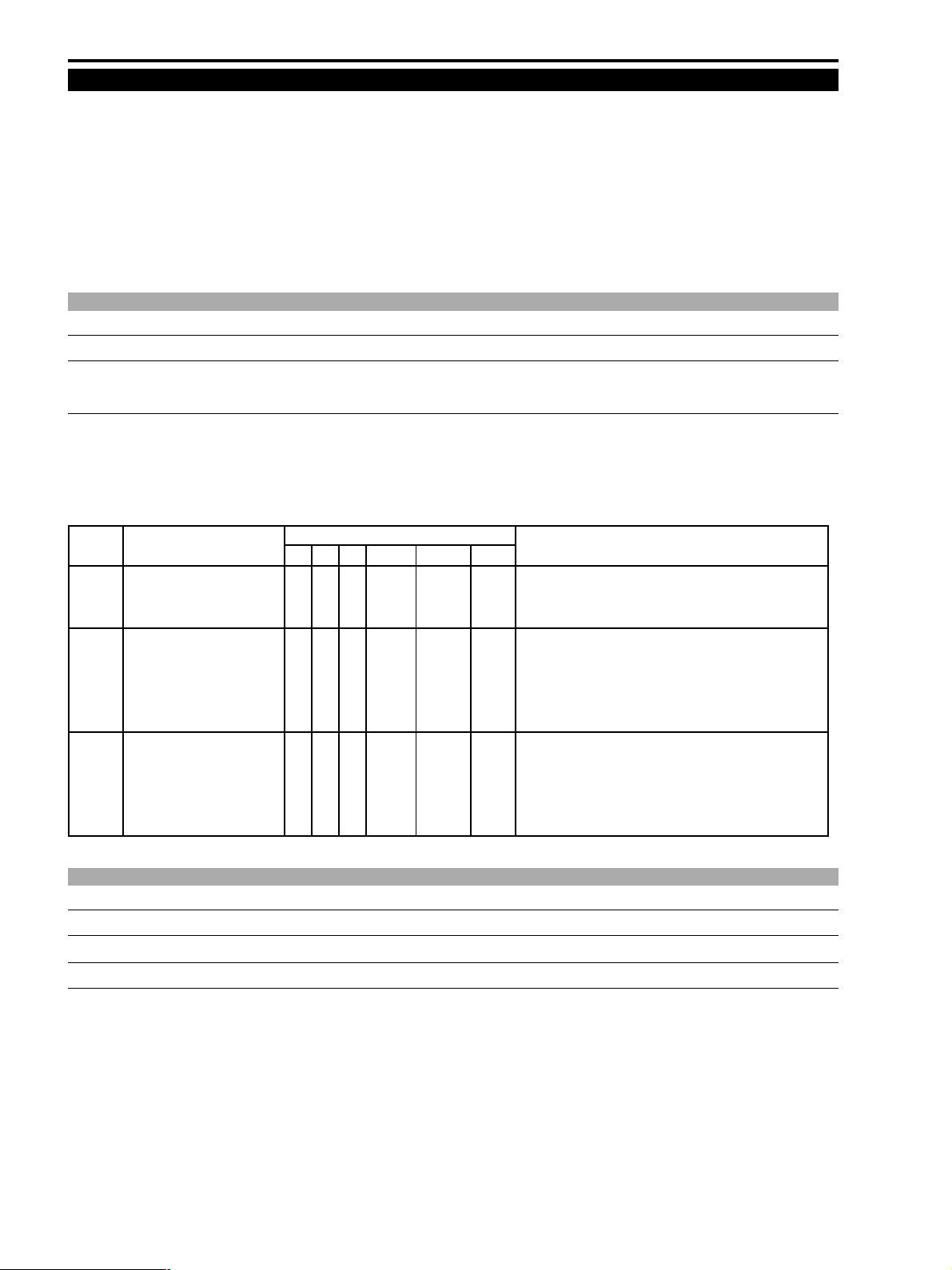
2-1 Adjustments after Part Replacement
When any of the following major parts is replaced, adjustment is required referring to the table shown below. Note that the
following table shows minimum required adjustments to be performed after any major part is replaced. Depending upon
the faulty condition or in case that two or more parts have been replaced, appropriate adjustments are required accordingly.
K : Adjustment is required
Camera system
Name of Part
No. Name of Adjustment
2-2 AF section
2-2-1 CZ Automatic Adjustment KKKProduct state
2-2-2 Zoom Performance Check KKKProduct state
2-3 IS section
2-3-1
2-3-2 GYRO GAIN Adjustment K Product state
2-3-3 E2PROM Write KKProduct state
2-4 Camera section
2-4-1 IRIS Encoder Adjustment K KKKProduct state
2-4-2 WB Adjustment (1) KKProduct state
2-4-3 Color Balance Adjustment KKProduct state
2-4-4 WB Automatic Adjustment (2) KKProduct state
2-4-5 WB Automatic Adjustment (3) KKProduct state
2-4-6 E2PROM Write K KKKProduct state
2-5 CCD Pixel Defect Compensation KKProduct state
GYRO OFFSET AUTO Adjustment
Lens
JACK
PCB PCB PCB
KKProduct state
CCD
PMCA MAIN
Setting during Adjustment
Recorder system
Name of Part
No. Name of Adjustment
2-6 Recorder section
2-6-1 Recorder Setting for Destination K Product state
2-6-2, 2-6-3 Y LEVEL/C LEVEL Adjustment K Product state
2-6-4 AGC Initial Value Adjustment K Product state
2-6-5 EQ Automatic Adjustment KK Product state
2-6-6 SWP Automatic Adjustment KK Product state
2-6-7 C. FG Automatic Adjustment KK Product state
2-6-8 Low Battery Voltage Adjustment K Product state
2-6-9 Charging Voltage Adjustment KK Product state
DMC II
2-7 Tape Path Adjustment Tape path adjustment setting
MAIN
DMC II
PCB PCB
PMCA
Setting during Adjustment
4-17
Page 16
ZR10A
CHAPTER 4. DISASSEMBLING ADJUSTMENT
2-2 AF Section Adjustment
Preparation)
(1) Perform the CZ automatic adjustment and zoom performance check after the machine is re-assembled to the product state.
(2) Adjustment conditions (default conditions)
Program AE : Auto Mode
ZOOM : Telephoto-end
CZ adjustment chart : 2.4±0.02 m from lens front
Chart luminance : 500 lux or more (High illumination object should be avoided at the wide-angle end.)
2-2-1 CZ Automatic Adjustment
CHART CZ adjustment chart (DY9-1372-000 : Same as conventional model’s)
SPEC. Data (DT) must become AA at the following step 3 and the specifications of the zoom performance check
must be satisfied.
Procedure)
(1) At the telephoto-end zoom position, bring the center of CZ adjustment chart to the center of monitor TV screen.
(2) Referring to the table shown below, perform the CZ automatic adjustment in the service mode.
(3) Upon completion of the adjustment, turn off the main power once then back on. Check the zoom performance.
STEP PROCEDURE MONITOR Microcomputer operation
CZ PG BK MD ADDR DT ST
1 1) Establish the setup as 5 3 WR **00 31 WAIT
shown in the right.
2) Press the STORE key. ↑↑RD ↑↑OK Setting the high address “31” is complete.
2 1) Establish the setup as 5 2 WR 3100 00 WAIT
shown in the right.
2) Press the STORE key. ↑↑↑ ↑ 01-08 BUSY Automatic adjustment starts. The adjustment completes in
about 30 seconds. If any trouble occurs during the
automatic adjustment, check the parts inside the lens block.
3 Make judgment depending 5 2 RD 3100 AA OK Adjustment is completed. (Result is successful.)
upon result of the adjustment Advance to the zoom performance check.
↑↑RD ↑ FF NG Adjustment is completed. (Result is unsuccessful.) Repeat
the above-described adjustment procedure again from the
beginning.
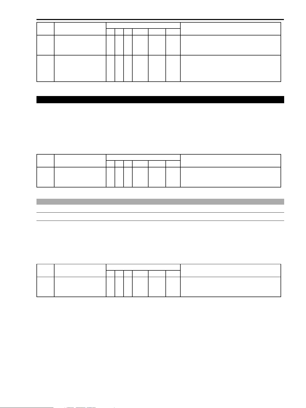
2-2-2 Zoom Performance Check
CHART CZ adjustment chart (DY9-1372-000 : Same as conventional model’s)
SPEC. “Data (DT) at address 19FC” must be equal to = “Data (DT) at address 19FE” must be equal to = “00”
“ Data (DT) at address 19FD” must be within “ Data (DT) at address 19FF±2 hexadecimal numbers”
Procedure)
(1) At the telephoto-end zoom position, bring the center of CZ adjustment chart to the center of monitor TV screen.
(2) Using the slow-speed zooming, move the lens zoom from the telephoto position to the wide-angle position. Make sure
that defocusing does not occur all the way.
(3) At the wide-angle position, focus the chart and then turn off AF.
(4) Referring to the following table, read out data at addresses 19FC to 19FF. Check them against the specified data
values.
(5) Turn off the main power then back on. Check that defocusing does not occur in ordinary zooming operation. (AF ON)
(6) If the results check at steps (2), (4) and (5) satisfy the specifications, this is the end of the adjustment. If the result does
not satisfy the specifications, perform CZ automatic adjustment again.
4-18
Page 17
CHAPTER 4. DISASSEMBLING ADJUSTMENT
STEP PROCEDURE MONITOR Microcomputer operation
ZOOMCHECK PG BK MD ADDR DT ST
1 1) Establish the setup as 5 3 WR **00 19 WAIT
shown in the right.
2) Press the STORE key. ↑↑RD ↑↑OK Setting the high address “19” is complete.
2
1) Read out DT (data) in the
setting shown in the right
5 2 RD 19FC “--” WAIT Data at address 19FC is indicated.
↑↑↑19FD “--” ↑ Data at address 19FD is indicated.
↑↑↑19FE “--” ↑ Data at address 19FE is indicated.
↑↑↑ 19FF “--” ↑ Data at address 19FF is indicated.
2-3 IS Section Adjustment
Preparation)
(1) Perform the IS adjustment after machine is re-assembled to a product status.
(2) Prepare a tripod or stable work bench.
<Preparation for IS adjustment>
(1) According to the following table, set the high address to enter the IS adjustment mode.
STEP PROCEDURE MONITOR Microcomputer operation
CZ PG BK MD ADDR DT ST
1 1) Establish the setup as 5 3 WR **00 32 WAIT
shown in the right.
2) Press the STORE key. ↑↑RD ↑↑OK Setting the high address “32” is complete.
ZR10A
2-3-1 GYRO OFFSET ATUO Adjustment
SPEC. Automatic adjustment
Procedure)
(1) Wait for 30 seconds or more without shaking the camera.
(2) Perform the adjustment referring to the table shown below.
Note) After the STORE key is pressed, it will take about 25 seconds at a maximum before completion of
adjustment (OK) message appears.
STEP PROCEDURE MONITOR Microcomputer operation
GYRO OFFSET PG BK MD ADDR DT ST
1 1) Establish the setup as 5 2 WR 3206 00 WAIT
shown in the right.
2) Press the STORE key. ↑↑RD ↑↑OK Adjustment is complete.
4-19
Page 18
ZR10A
CHAPTER 4. DISASSEMBLING ADJUSTMENT
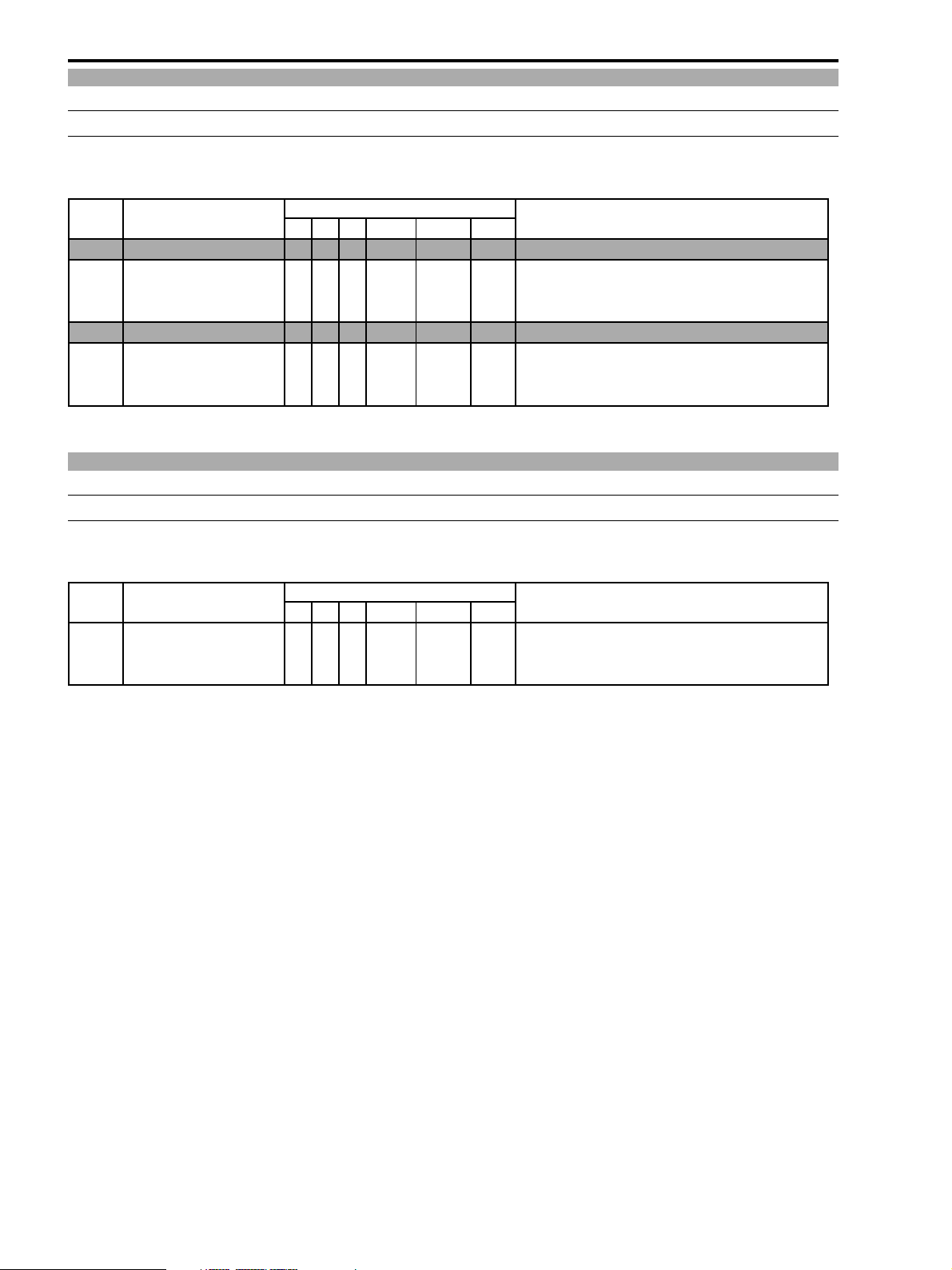
2-3-2 GYRO GAIN Adjustment
SPEC. Data writing
Procedure)
(1) Write the data referring to the table shown below.
STEP PROCEDURE MONITOR Microcomputer operation
GYRO GAIN PG BK MD ADDR DT ST
1 Gyro YAW gain adjustment
1-1 1) Establish the setup as 5 2 WR 3200 83 WAIT
shown in the right.
2) Press the STORE key. ↑↑RD ↑↑OK Adjustment is complete.
2 Gyro PITCH gain adjustment
2-1 1) Establish the setup as 5 2 WR 3201 81 WAIT
shown in the right.
2) Press the STORE key. ↑↑RD ↑↑↑Adjustment is complete.
2-3-3 E2PROM Write
SPEC. Automatic write
Procedure)
(1) Write the adjustment data of 2-3-1 and 2-3-2 referring to the table shown below.
STEP PROCEDURE MONITOR Microcomputer operation
E2PROM WRITING PG BK MD ADDR DT ST
1 1) Establish the setup as 5 2 WR 3208 00 WAIT
shown in the right.
2) Press the STORE key. ↑↑RD ↑↑OK Writing is complete.
4-20
Page 19
ZR10A
CHAPTER 4. DISASSEMBLING ADJUSTMENT
2-4 Camera Section Adjustment
Note)
1) Each adjustment data (section 2-4-1 to section 2-4-5) becomes valid after it is written into the E2PROM as described
in section 2-4-6. Before turning the main power off or on during each adjustment, be sure to perform the write
procedure of data to E2PROM write procedure following the description in section 2-4-6.
2) Perform the adjustments 2-4-2 to 2-4-5 consecutively. If they are performed independently, the result may not be
accurate.
Preparation)
(1) Perform the camera section adjustment after the machine is re-assembled to the product state with the camera adjust-
ment setup.
(2) Adjusting conditions (default setting)
Program AE : Auto Mode
AF : OFF
Camera-shake compensation : OFF
Chart : Standard view angle (Set the angle after setting the high address.)
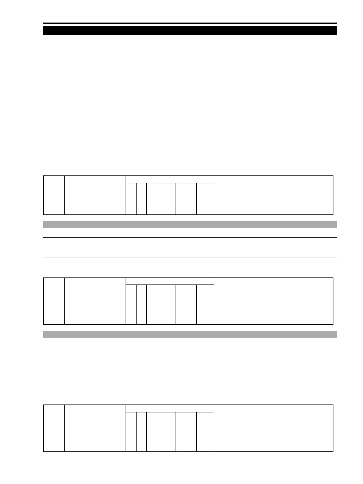
<Preparation for camera adjustment>
(1) Set the high address for camera adjustment mode referring to the table shown below.
STEP PROCEDURE MONITOR Microcomputer operation
CAM ADJ MODE PG BK MD ADDR DT ST
1 1) Establish the setup as 5 3 WR **00 30 WAIT
shown in the right.
2) Press the STORE key. ↑↑RD ↑↑OK Setting the high address “30” is complete.
2-4-1 IRIS Encoder Adjustment
CHART Light box (5600° K)
SPEC. Automatic adjustment
Procedure)
(1) Adjust the IRIS encoder referring to the table shown below.
STEP PROCEDURE MONITOR Microcomputer operation
IRIS ENC./AGC TRACKING PG BK MD ADDR DT ST
1 1) Establish the setup as 5 2 WR 3000 00 WAIT
shown in the right.
2) Press the STORE key. ↑↑WR ↑↑BUSY Adjustment is in progress.
↑↑RD ↑↑OK Adjustment is complete.
2-4-2 WB Adjustment (1)
CHART Light box (5600° K)
SPEC. Automatic adjustment
Note)
This adjustment sets the gain data of color balance as “FF”. So, be sure to perform the color balance adjustment (2-4-3).
Procedure)
(1) Perform the WB adjustment (1) referring to the table below.
STEP PROCEDURE MONITOR Microcomputer operation
WB (1) PG BK MD ADDR DT ST
1 1) Establish the setup as 5 2 WR 3002 00 WAIT
shown in the right.
2) Press the STORE key. ↑↑WR ↑↑BUSY Adjustment is in progress.
↑↑RD ↑↑OK Adjustment is complete.
4-21
Page 20
ZR10A
CHAPTER 4. DISASSEMBLING ADJUSTMENT
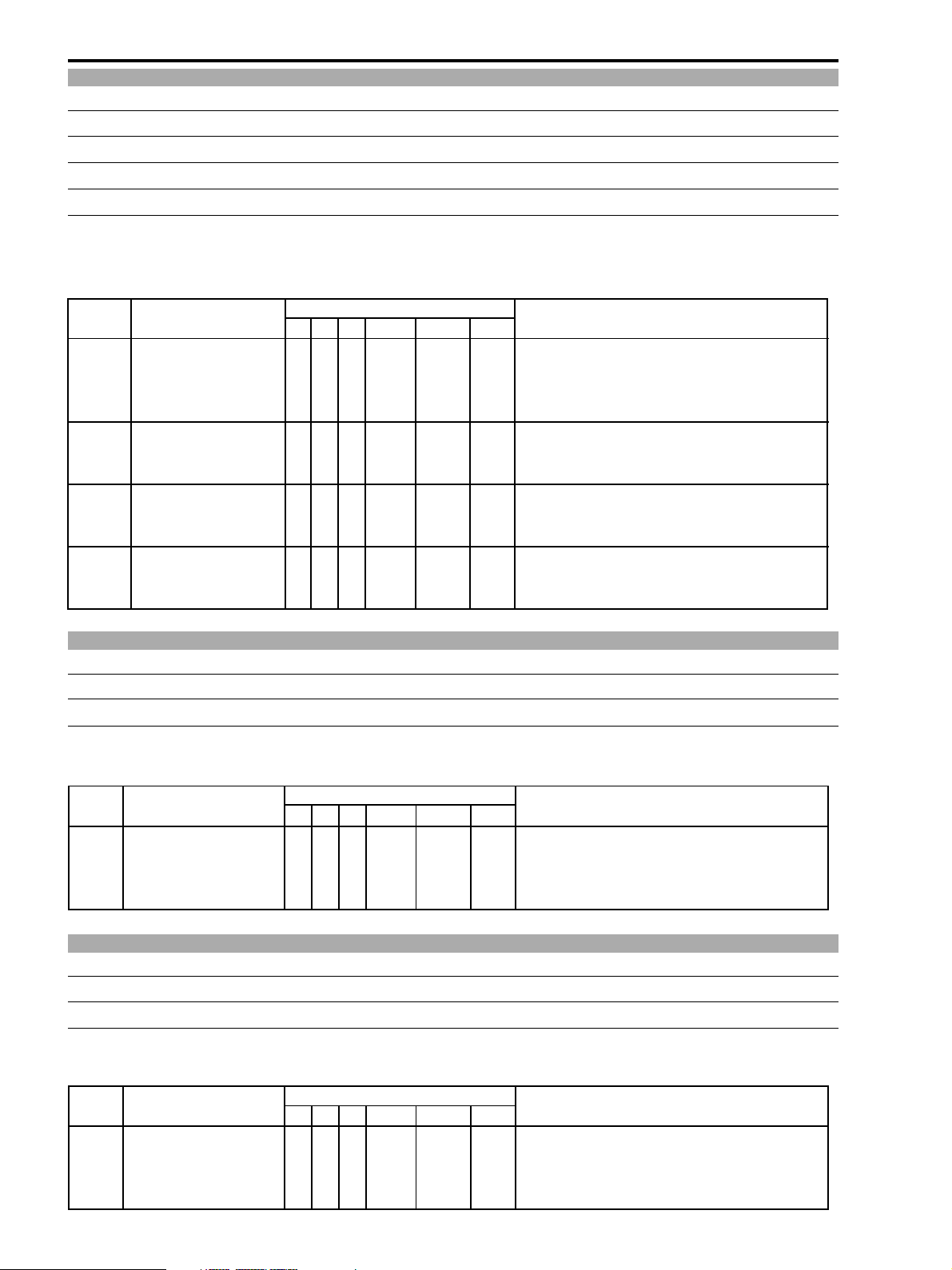
2-4-3 Color Balance Adjustment
CHART Light box (5600° K), and color bar chart
M. EQ. Vector scope
TP/TRIG. VIDEO OUT
SPEC. Red : ×2.0 (ratio to burst) 106°, Yellow : ×1.4 (ratio to burst) 162°
Procedure)
(1) Perform the manual color balance adjustment by changing data at the following four addresses while observing the red
and yellow spots on a vector scope.
STEP PROCEDURE MONITOR Microcomputer operation
CB (MANUAL) PG BK MD ADDR DT ST
R-Y GAIN
B-Y GAIN 1) Establish the setup as ↑↑↑ 3008 “ADJ” WAIT Adjustment is in progress.
R-Y MAT 1) Establish the setup as ↑↑↑ 3009 “ADJ” WAIT Adjustment is in progress.
B-Y MAT 1) Establish the setup as ↑↑↑ 300A “ADJ” WAIT Adjustment is in progress.
1) With the setting shown in the
right, adjust data for the
desired value.
2) Press the STORE key. ↑↑↑ ↑ ADJ OK Adjustment is complete.
shown in the right.
2) Press the STORE key. ↑↑↑ ↑ ADJ OK Adjustment is complete.
shown in the right.
2) Press the STORE key. ↑↑↑ ↑ ADJ OK Adjustment is complete.
shown in the right.
2) Press the STORE key. ↑↑↑ ↑ ADJ OK Adjustment is complete.
5 2 WR 3007 “ADJ” WAIT Adjustment is in progress.
2-4-4 WB Automatic Adjustment (2)
CHART Light box (5600° K), and CCA12 filter
SPEC. Automatic adjustment
Procedure)
(1) Perform the WB automatic adjustment (2) referring to the table below.
STEP PROCEDURE MONITOR Microcomputer operation
WB (2) PG BK MD ADDR DT ST
1 1) Establish the setup as 5 2 WR 3004 00 WAIT
shown in the right.
2) Press the STORE key. ↑↑WR ↑↑BUSY Adjustment is in progress.
↑↑RD ↑↑OK Adjustment is complete.
2-4-5 WB Automatic Adjustment (3)
CHART Light box (5600° K)
SPEC. Automatic adjustment
Procedure)
(1) Perform the WB automatic adjustment (3) referring to the table below.
STEP PROCEDURE MONITOR Microcomputer operation
WB (3) PG BK MD ADDR DT ST
1 1) Establish the setup as 5 2 WR 3005 00 WAIT
shown in the right.
2) Press the STORE key. ↑↑WR ↑↑BUSY Adjustment is in progress.
↑↑RD ↑↑OK Adjustment is complete.
4-22
Page 21
ZR10A
CHAPTER 4. DISASSEMBLING ADJUSTMENT
2-4-6 E2PROM Write
SPEC. Automatic write.
Procedure)
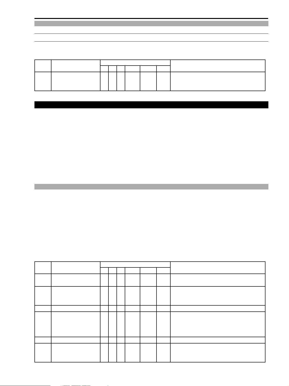
(1) Write the adjustment data (section 2-4-1 to section 2-4-5) into the E2PROM referring to the table below.
STEP PROCEDURE MONITOR Microcomputer operation
E2PROM WRITING PG BK MD ADDR DT ST
1 1) Establish the setup as 5 2 WR 3006 00 WAIT
shown in the right.
2) Press the STORE key. ↑↑RD ↑↑OK Writing is complete.
2-5 CCD Pixel Defect Compensation
Note)
(1) Perform this adjustment only if defective pixel of the CCD is visible on screen.
(2) Before starting this adjustment, turn on the main power for more than 30 minutes.
(3) The automatic mode (2-5-1) and the manual mode (2-5-2) are available for this adjustment. In the automatic adjust-
ment mode, “NG” is recognized, if there are more than two defective pixels in the center area of the screen or more
than eight defective pixels over the entire area of a screen. (If “NG” is recognized, the automatic pixel defect compen-
sation is not performed.) In the manual adjustment mode, it is allowed to correct up to eight defective pixels over the
entire area of a screen. In the manual adjustment mode, an arbitrary point up to a maximum of eight points can be
selected for correction.
2-5-1 CCD Pixel Defect Compensation (Automatic Compensation)
Preparation)
(1) Perform this compensation after machine is re-assembled to a product status.
(2) Adjustment Conditions
Program AE : AUTO
AF : OFF
Camera-shake compensation : OFF
Electronic zoom : OFF
Procedure)
(1) Perform the CCD pixel defect compensation (automatic compensation mode) according to the table shown below.
STEP PROCEDURE MONITOR Microcomputer operation
PG BK MD ADDR DT ST
1 Setting the high address to
enter the compensation mode.
1-1 1) Establish the setup as 5 3 WR **00 30 WAIT
shown in the right.
2) Press the STORE key. ↑↑RD ↑↑OK Setting the high address “30” is complete.
2 CCD pixel defect compensation
2-1 1) Establish the setup as 5 2 WR 300E 00 WAIT
shown in the right.
2) Press the STORE key. ↑↑↑ ↑ ↑ BUSY Adjustment is in progress.
↑↑RD ↑ -- OK Adjustment is complete. (*)
3 E2PROM writing
3-1 1) Establish the setup as 5 2 WR 300F 00 WAIT
shown in the right.
2) Press the STORE key. ↑↑RD ↑↑OK Writing is complete.
* “NG” appears in case that data (DT) is FF even “OK” is shown on status (ST).
4-23
Page 22
ZR10A
CHAPTER 4. DISASSEMBLING ADJUSTMENT
2-5-2 CCD Pixel Defect Compensation (Manual Compensation)
Note)
(1) Use of a full-scanned monitor is recommended for this adjustment.
Preparation)
(1) Perform this compensation after machine is re-assembled to a product status.
(2) Adjustment Conditions
Program AE : LOW LIGHT
AF : OFF
Camera-shake compensation : OFF
Electronic zoom : OFF
M.E.Q. Monitor TV
Procedure)
(1) Before entering the service mode, press the data screen key on the LANC remote controller to turn off the data screen.
(2) Enter the service mode, then set up the CCD pixel defect compensation mode (manual compensation mode) following
the table given below.
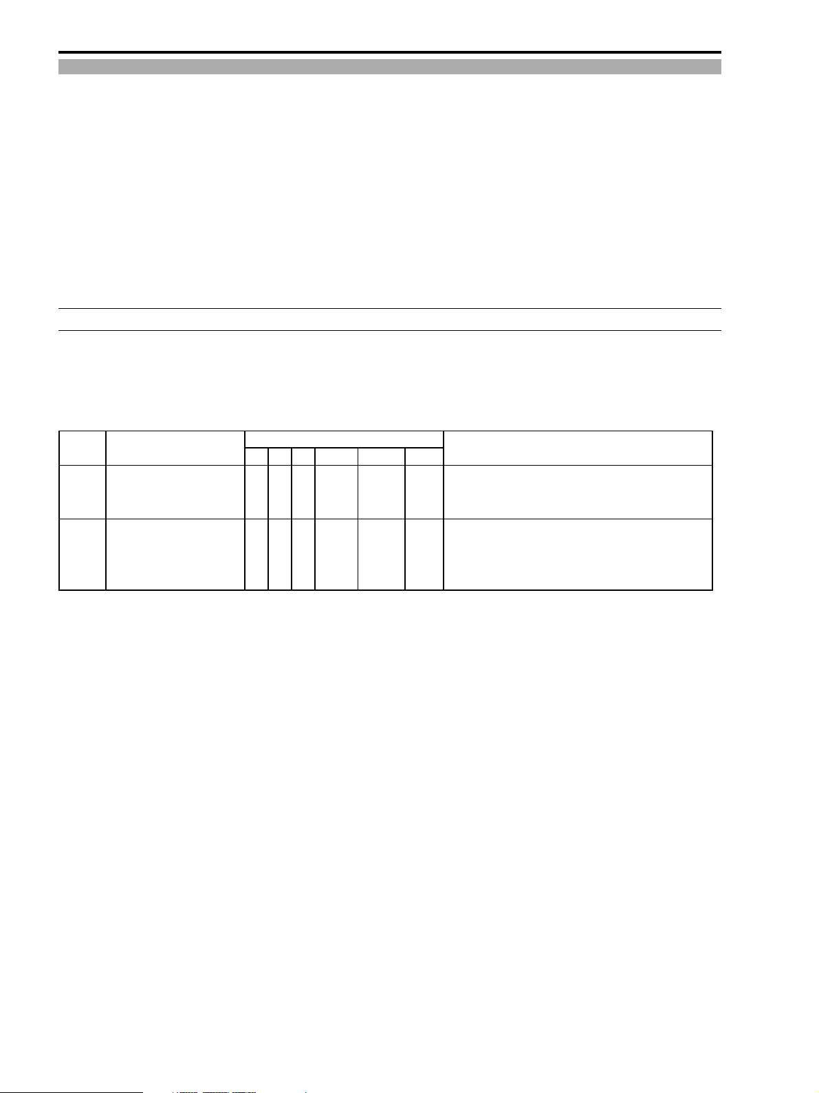
STEP PROCEDURE MONITOR Microcomputer operation
CCD PIXEL MISSING COMP. PG BK MD ADDR DT ST
1 1) Establish the setup as 5 3 WR **00 FF WAIT
shown in the right.
2) Press the STORE key. ↑↑RD ↑↑OK Setting the high address “FF” is complete.
2 1) Establish the setup as 5 2 RD FF00 00 WAIT Entering the CCD pixel missing compensation mode is
shown in the right. complete. (AGC MAX., Iris close, H-direction enlargement
for electronic processing for camera-shake compensation is
canceled)
(3) Press the data screen key on the LANC remote controller to turn off the data screen.
(4) Move an un-used marker (positioned in the left of the screen) to the position where a pixel is missing. The un-used
marker can be moved by changing the data at the address corresponding to each marker. The addresses corresponding
to the markers are shown in Fig. 4-19.
Note) The markers having odd numbers correspond to the odd number lines. The markers having numbers correspond to
the even number lines. When the marker that corresponds to the line containing the pixel defect, cannot be used,
use the marker of different line.
(5) When a pixel defect in the area (vertical direction) that is used for the camera-shake compensation, is going to be
compensated, move the picture area as follows : Select PG-5, BK-2, ADDR FFFF and set data DT-01 then the picture
moved upward in the CCD area. Select the same page, block and address, and set data DT-03 then the picture moved
downward in the CCD area. After accessing the desired area of CCD, perform compensation. (As to the horizontal
direction, the horizontal area including the camera-shake compensation area is shown on screen when the camera
enters the compensation mode.)
4-24
Page 23
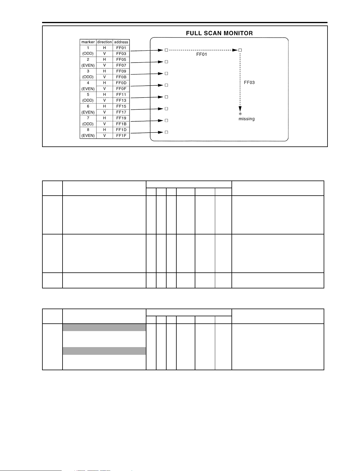
Fig. 4-19
* The following table shows the procedure to move the marker 1.
ZR10A
CHAPTER 4. DISASSEMBLING ADJUSTMENT
STEP PROCEDURE MONITOR Microcomputer operation
CCD PIXEL MISSING COMP. PG BK MD ADDR DT ST
1 1) Specify address in the H direction and 5 2 WR FF01 36 WAIT
enter the WR mode.
2) Change the data then move the marker ↑↑↑ ↑ ADJ ↑
(H direction).
3) Press the STORE key. ↑↑↑ ↑ ↑ OK
2 1) Specify address in the V direction and 5 2 WR FF03 70 WAIT
enter the WR mode.
2) Change the data then move the marker ↑↑↑ ↑ ADJ ↑
(H direction).
2) Press the STORE key. ↑↑↑ ↑ ↑ OK
3 Repeat steps 1 and 2, and align the marker
with the position where pixel is missing.
(6) Write the compensation data into E2PROM according to the table below.
STEP PROCEDURE MONITOR Microcomputer operation
CCD PIXEL MISSING COMP. PG BK MD ADDR DT ST
1 In case that marker is either one of 1 to 4
1) Establish the setup as shown in the right. 5 2 WR FF20 00 WAIT
2) Press the STORE key. ↑↑RD ↑↑OK Writing is complete.
In case that marker is either one of 5 to 8
1) Establish the setup as shown in the right. 5 2 WR FF21 00 WAIT
2) Press the STORE key. ↑↑RD ↑↑OK Writing is complete.
(7) Exit the service mode and close the lens. Ten seconds later, check that pixel defects have been compensated.
Notes)
(1) Because size of marker is larger than that of a pixel, that can be cases that a marker does not agree with the desired
pixel although they look superposed each other during adjustment.
(2) When two markers are overlapped each other or they are located as close as ±2 hexadecimal addresses in both the V
and H directions, writing the compensation data is impossible.
4-25
Page 24
ZR10A
CHAPTER 4. DISASSEMBLING ADJUSTMENT
2-6 Recorder Section Adjustment
Preparation)
(1) Except the Tape Path Adjustment, perform the Recorder Section Adjustment after the machine is re-assembled to the
product state.
2-6-1 Recorder Setting for Destination
SPEC. Automatic write
Procedure)
(1) Set the recorder for destination market referring to the table shown below.
STEP PROCEDURE MONITOR Microcomputer operation
RECORDER DESTINATION PG BK MD ADDR DT ST
1 1) Establish the setup as shown in the right. 6 5 WR **00 01
2) Press the STORE key. ↑↑RD ↑↑* Setting the high address “01” is complete.
2 1) Establish the setup as shown in the right. 6 4 WR 0112 F0 Function Select bit for USA
(USA MODEL)
1) Establish the setup as shown in the right. 6 4 WR 0112 F1 Function Select bit for JPN
(JPN MODEL)
2) Press the STORE key. ↑↑RD ↑ F0orF1 * The recorder setting for destination market is
complete.
2-6-2 Y LEVEL Adjustment
TP/TRIG. VIDEO OUT
M. EQ. Oscilloscope
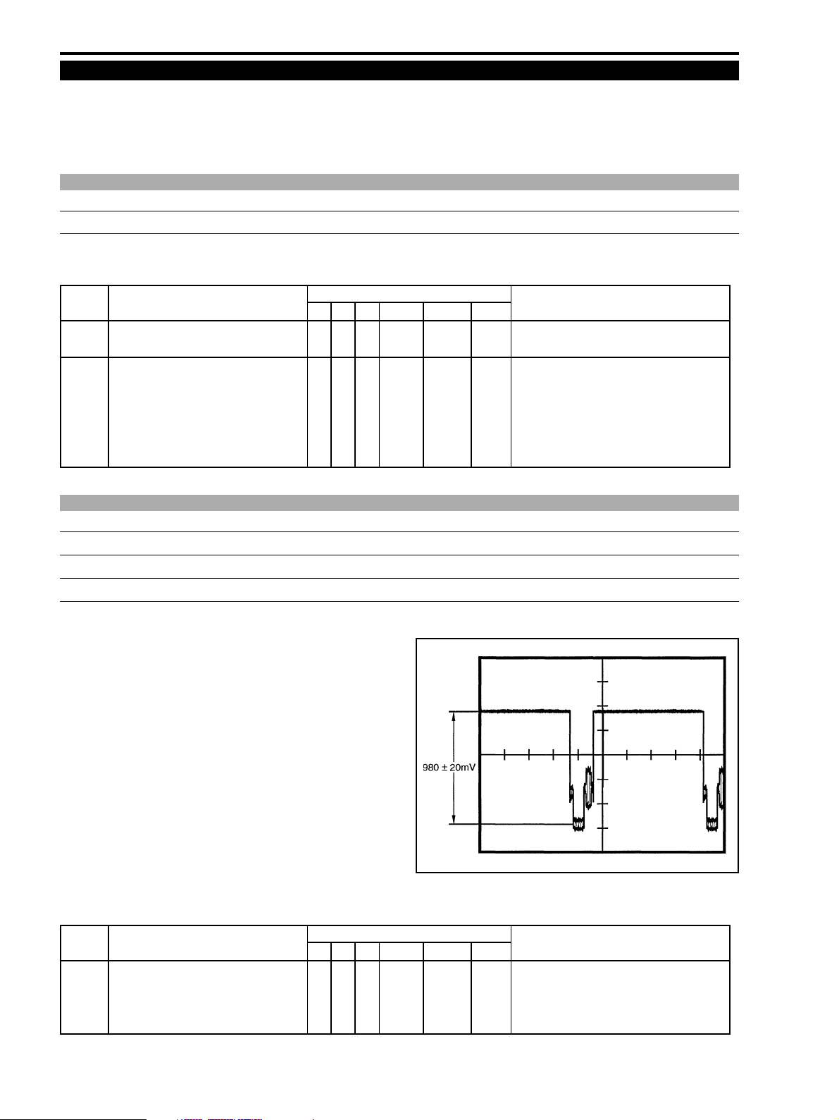
SPEC. Y : 980±20 [mV]
Procedure)
(1) Perform the Y level adjustment referring to the table shown
below.
Fig. 4-20
STEP PROCEDURE MONITOR Microcomputer operation
Y LEVEL PG BK MD ADDR DT ST
1 1) Establish the setup as shown in the right. 6 4 WR 001E ADJ White raster output.
2) Change data (DT) to satisfy the ↑↑↑ ↑ “ADJ” Adjustment is in progress.
specifications.
2) Press the STORE key. ↑↑RD ↑↑* Adjustment is complete.
4-26
Page 25
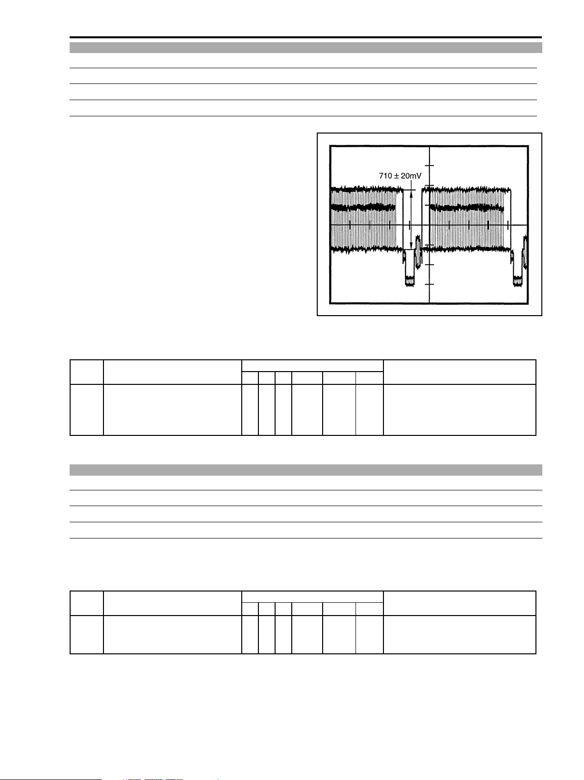
2-6-3 C LEVEL Adjustment
TP/TRIG. VIDEO OUT
M. EQ. Oscilloscope
SPEC. Y : 710±20 [mV]
Procedure)
(1) Perform the C level adjustment referring to the table
shown below.
ZR10A
CHAPTER 4. DISASSEMBLING ADJUSTMENT
Fig. 4-21
STEP PROCEDURE MONITOR Microcomputer operation
C LEVEL PG BK MD ADDR DT ST
1 1) Establish the setup as shown in the right. 6 4 WR 001F ADJ Green raster output.
2) Change data (DT) to satisfy the ↑↑↑ ↑ “ADJ” Adjustment is in progress.
specifications.
2) Press the STORE key. ↑↑RD ↑↑* Adjustment is complete.
2-6-4 AGC Initial Value Adjustment
SIGNAL COLOR BAR
MODE E-E (ANALOG LINE IN)
SPEC. Automatic write
Procedure)
(1) Connect color bar signal from a pattern generator to the analog LINE IN connector.
(2) Perform the AGC initial value adjustment following the table below.
STEP PROCEDURE MONITOR Microcomputer operation
PG BK MD ADDR DT ST
1 1) Establish the setup as shown in the right. 7 0 WR **04 --
2) Change data (DT) to satisfy the ↑↑↑ ↑ ↑ + Automatic adjustment is in progress.
specifications. ↑↑RD ↑↑* Adjustment is complete.
4-27
Page 26
ZR10A
CHAPTER 4. DISASSEMBLING ADJUSTMENT
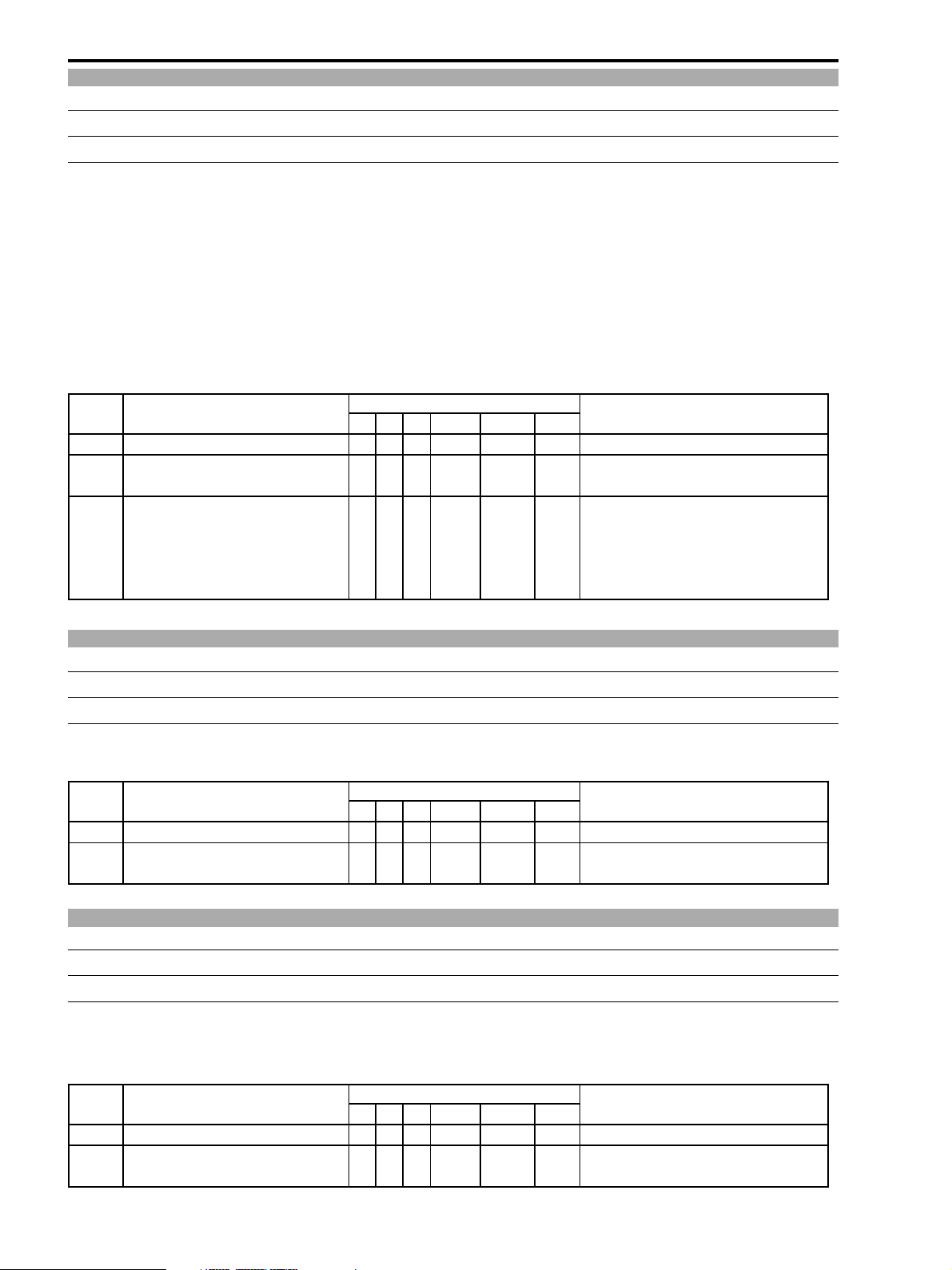
2-6-5 EQ Automatic Adjustment
MODE Playing back the self-recorded LP tape. (The tape conforming to the LP tape manufactured by Panasonic)
SPEC. The error rate should be 2×10⁻⁵ or less after adjustment.
Notes)
(1) For error rate measurement, use a tape conforming to the LP tape manufactured by Panasonic.
(2) Use the Recorder menu in order to select either SP or LP mode for recording.
Procedure)
(1) Perform the EQ automatic adjustment referring to the table shown below.
(2) Upon completion of adjustment, play back the self-recorded segment of the LP tape again and check that the error rate
is within the allowable range of specifications.
(3) If the result of check is NG, perform the EQ automatic adjustment using the self-recording SP tape. Then, with this LP
tape, perform EQ automatic adjustment again.
STEP PROCEDURE MONITOR Microcomputer operation
EQ (AUTO) PG BK MD ADDR DT ST
1 1) Start LP recording.
2 1) Rewind the recorded segment and start
playing back in LP.
3 1) During LP playback, establish the setup 7 0 WR **02 --
as shown in the right.
2) Press the STORE key. ↑↑↑ ↑ ↑ + Automatic adjustment is in progress.
(For about ten seconds)
↑↑RD ↑↑* Adjustment is complete.
2-6-6 SWP Automatic Adjustment
MODE Playing back the color bar master tape (DY9-1321-000)
SPEC. Automatic adjustment
Procedure)
(1) While playing back the color bar master, perform the SWP automatic adjustment referring the table shown below.
STEP PROCEDURE MONITOR Microcomputer operation
SWP (AUTO) PG BK MD ADDR DT ST
1 1) Establish the setup as shown in the right. 7 0 WR **01 --
2) Press the STORE key. ↑↑↑ ↑ ↑ + Automatic adjustment is in progress.
↑↑RD ↑↑* Adjustment is complete.
2-6-7 C.FG Automatic Adjustment
MODE Playing back the color bar master tape (DY9-1321-000)
SPEC. Automatic adjustment
Procedure)
(1) While playing back the color bar master tape, perform the C.FG automatic adjustment referring the table shown
below.
STEP PROCEDURE MONITOR Microcomputer operation
C.FG (AUTO) PG BK MD ADDR DT ST
1 1) Establish the setup as shown in the right. 7 0 WR **03 --
2) Press the STORE key. ↑↑↑ ↑ ↑ + Automatic adjustment is in progress.
↑↑RD ↑↑* Adjustment is complete.
4-28
Page 27
CHAPTER 4. DISASSEMBLING ADJUSTMENT
2-6-8 Low Battery Voltage Adjustment
MODE During the camera recording mode after the machine is re-assembled to the product state.
(AF : OFF, LCD PANEL : ON)
SPEC. Power supply voltage : 5.80±0.02 [V]
Procedure)
(1) Under the above-described conditions, set an external DC power voltage at 5.80±0.02 [V].
(2) Perform the low battery voltage adjustment referring to the table shown below.
Note)
Be sure to start adjustment after 4 seconds have elapsed since the start of recording.
STEP PROCEDURE MONITOR Microcomputer operation
Low battery voltage PG BK MD ADDR DT ST
1 1) Establish the setup as shown in the right. 7 2 WR **FF “ADJ”
2) Press the STORE key. ↑↑RD ↑↑* Adjustment is complete.
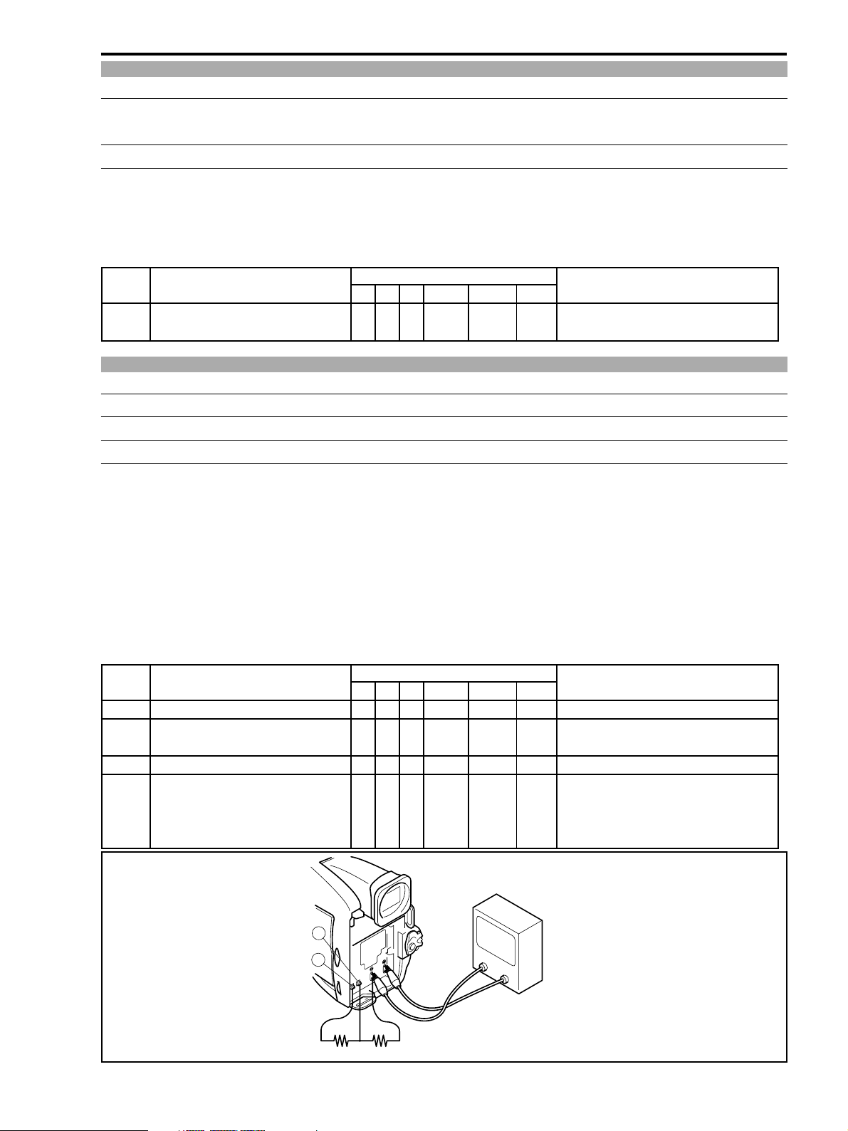
2-6-9 Charging Voltage Adjustment
MODE VTR STOP
TP Battery terminals + and -
SPEC. 8.40±0.02 V
ZR10A
Preparation)
(1) Connect a resistor to the terminals B and D as shown in Fig. 4-22.
(2) Supply an external DC power to the DC IN terminal of the main unit from the CA-56 or CG-560.
Procedure)
(1) Measure voltage between the positive (+) and negative (-) terminal of the battery terminal.
(2) Referring to the following table, change data as much as difference between the actual measured voltage and specifi-
cation voltage, and press the STORE key. (Increasing the data by one bit raises the voltage by 20 mV. Decreasing the
data by one bit lowers the voltage by 20 mV.
Note)
The changed data is reflected on the charging voltage only after the POWER is once turned off then back on.
STEP PROCEDURE MONITOR Microcomputer operation
PG BK MD ADDR DT ST
1 Setting the high address
1-1 1) Establish the setup as shown in the right. 6 5 WR **00 01
2) Press the STORE key. ↑↑RD ↑↑* Setting the high address “01” is complete.
2 Charging voltage adjustment
2-1 1) Establish the setup as shown in the right. 6 4 WR 01A5 ADJ
2) Change data (DT) to satisfy the ↑↑↑ ↑ “ADJ” ↑ Adjustment is in progress.
specifications.
3) Press the STORE key. ↑↑RD ↑↑* Adjustment is complete.
D
B
43 KΩ 56 KΩ
VOLTAGE METER
Fig. 4-22
4-29
Page 28
ZR10A
CHAPTER 4. DISASSEMBLING ADJUSTMENT
2-7 Tape Path Adjustment
Note)
(1) The service mode must be established in order to perform the tape path adjustment. For the details of the “Tape Path
Adjustment” procedure, refer to the DMC II Service Manual separately issued.
Preparation)
(1) For the tape path adjustment, use the recorder adjustment setting. (P.3-4)
Procedure)
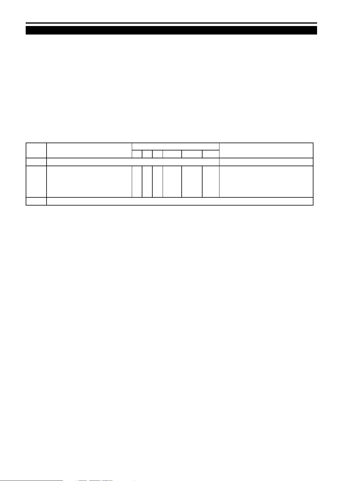
(1) Perform the tape path adjustment by playing back the tracking master (DY9-1345-000) referring to the table given
below. At step 2 of the following adjustment, adjust data (DT) in a range of 01 to 0F to shift the tracking so that the RF
envelope amplitude becomes 70% of the standard tracking. Then perform the tape path adjustment at step 3.
(2) After adjustment is complete, restore tracking shift back to the normal condition (DT : 00) of the product specifica-
tions.
STEP PROCEDURE MONITOR Microcomputer operation
TRACKINGTAPE PG BK MD ADDR DT ST
1 1) Play back the tracking tape.
2 1) Establish the setup as shown in the right 7 0 WR **FE 00 Standard product specifications.
while playing back the tracking tape.
2) Perform 70% tracking shift by changing ↑↑↑ ↑ 01-0F Amount of tracking shift is being changed.
data (DT) in a range of 01 to 0F.
3 1) Perform the tape path adjustment with the RF envelope shifted to the 70% tracking position.
4-30
 Loading...