

Page 1
CHAPTER 3. INFORMATION FOR REPAIR • SERVICE HINTS
1. Lists of Maintenance Tools and Materials
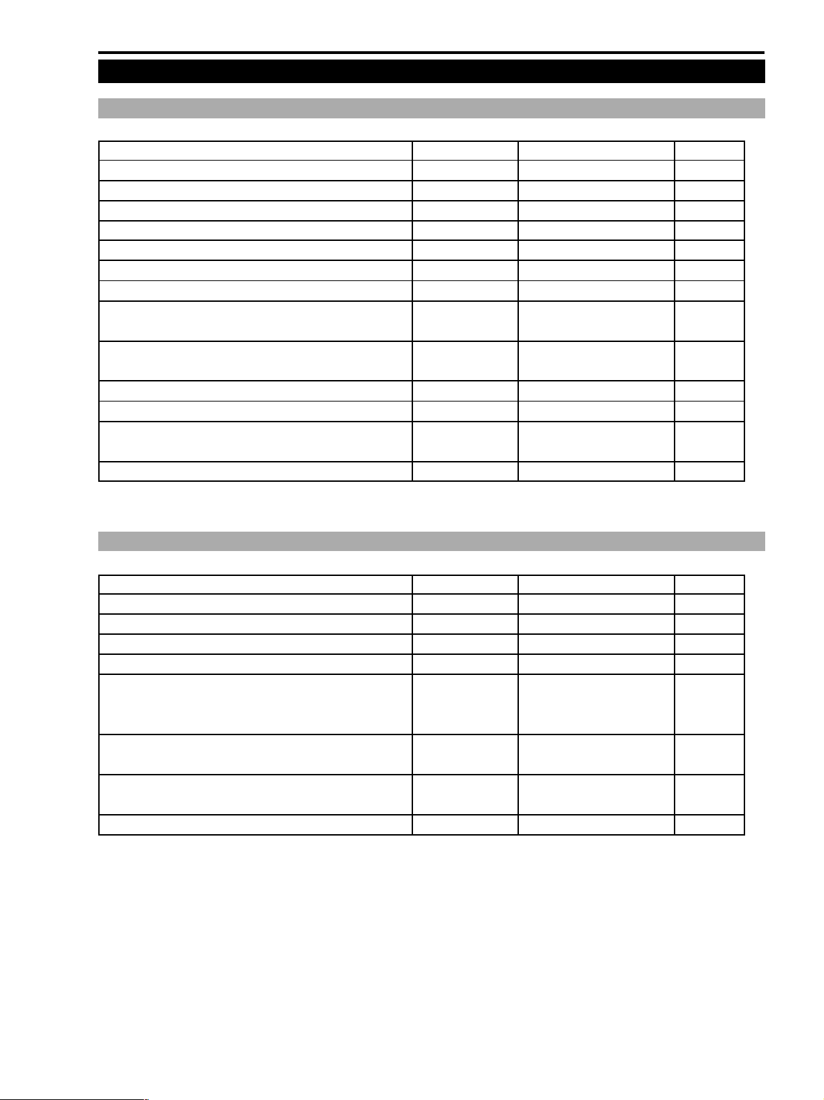
1-1 List of Maintenance Tools
Name Tool number Used for Remarks
Alignment Tape (Color bar master/NTSC) DY9-1321-000 Recorder electrical adjustment
Alignment tape (tracking) DY9-1345-000 Tape run adjustment DMC II
Torque gauge cassette for DV DY9-1346-000 Tape run adjustment DMC II
Cleaning tape (normal) — Commercially available DMC II
DV cleaning tape (hard) DY9-1359-000 Head cleaning DMC II
Driver bit for running adjustment DY9-2053-000 Tape run adjustment DMC II
Color bar chart DY9-2002-000 Camera electrical adjustment
Color Viewer 5600° K for 100V DY9-2039-100 Camera electrical adjustment
(JPN)
Color Viewer 5600° K for 115V DY9-2039-115 Camera electrical adjustment
(USA)
Lamp for Color Viewer 5600K DY9-2040-000 Replacement
Filter, CCA W12ø 46mm DY9-2046-000 Camera electrical adjustment
Remote commander RM-95 DY9-1349-000 Service mode, electrical
adjustment
CZ/Siemens Chart DY9-1372-000 CZ adjustment *
* Same chart as the conventional model’s.
ZR10A
1-2 List of Materials
Name Tool number Used for Remarks
Logenest Lambda A-74 CY9-8102-000 Lubrication Lens
Grease GE-C9 CY9-8443-000 Lubrication Lens
Grease GE-X8 CY9-8044-000 Lubrication Lens
Hanarl KS-50 DY9-3047-000 Lubrication Cover
Sponge (W×H×T : 300 mm×200 mm×6 mm) DY9-4001-000 General-purpose vibration
isolating/sound absorbing
material
Adhesive tape, No. 354E DY9-3032-000 General-purpose adhesive tape
(W×L×T : 9 mm×50 m×0.15 mm, UL type)
Adhesive tape, No. 501F DY9-3034-000 General-purpose double-side(W×L×T : 10 mm×50 m×0.16 mm, UL type) coated adhesive tape
Sheet, Shield (W×H : 250 mm×250 mm) DY9-3036-000 General-purpose shield material
3-3
Page 2
ZR10A
CHAPTER 3. INFORMATION FOR REPAIR • SERVICE HINTS
2. Settings
The AF/EIS/CAMERA adjustments must be performed after the disassembled parts and blocks, if they are disassembled
for service, are completely re-assembled back to a complete product.
2-1 Setting for Recorder Adjustment
<Purpose>
Each block is checked, tape run is adjusted and electrical adjustments of recorder are performed.
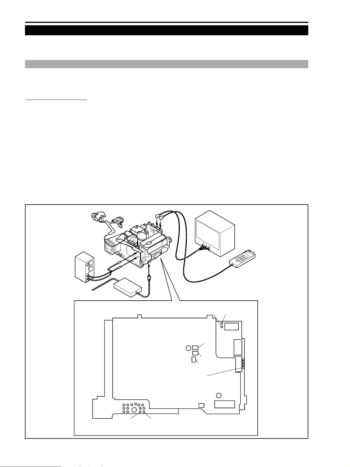
2-1-1 Setup Procedure
(1) Remove all the covers except the rear cover.
(2) Remove the POWER KEY UNIT from the LEFT COVER UNIT. Connect the POWER KEY UNIT to the CN254 of
LI P.C.B. (For turning on and off the main power.) Alternately, the main power can be turned on by connecting
TP202 (CAM PW SW) or TP203 (VTR PW SW) to GND on the MAIN P.C.B. in stead of the POWER KEY UNIT.
(3) Connecting the main power
The main power can be connected by any of the following three methods.
1 Supplying the DC power to the DC IN connector of the main unit using the CA-560.
2 Supplying the DC power to the battery terminal of the main unit using an external constant power supply (7.4 V).
3 Supplying the DC power across TP3201 (UNREG) and TP3202 (GND) on the PMCA P.C.B. using an external
constant power supply (7.4 V). (In this connection, the main unit can be operated without connecting the LI P.C.B.
and by turning on the main power by TP201 and TP202.)
POWER-KEY UNIT
LI P.C.B. CN254
CA-560
A/V JACK
DC IN
PMCA P.C.B.
LANC
JACK
TP2001
(PB-RF)
FU3201
TP3201
(UNREG)
FP212
(EJECT SW)
Short to GND: EJECT
FU3203
FU3202
MONITOR TV
REMOTE
COMMANDER
RM-95
TP2002
(SWP)
TP3202
(GND)
MAIN P.C.B.
TP202
(CAM PW SW)
GND: ON
FU3204
TP203
(VTR PW SW)
GND: ON
Fig. 3-1
3-4
Page 3
CHAPTER 3. INFORMATION FOR REPAIR • SERVICE HINTS
3. How to Use Service Remote Controller (DY9-1349-000)
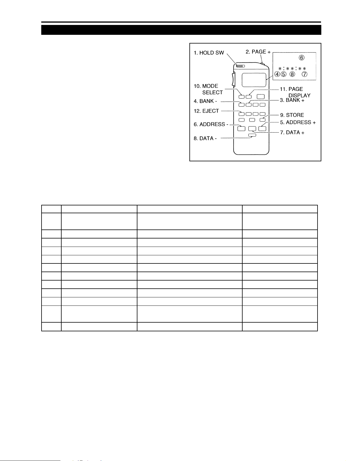
(1) Connect the service remote controller to the LANC termi-
nal.
(2) To establish the service mode, set the HOLD SW to the
HOLD position. When the HOLD SW is set back to its
original position, the product is controlled normally using
its original functions.
(3) LCD indications in the service mode :
4 PAGE is indicated while the FOCUS KEY is pressed
down.
5 BANK is indicated.
6 MODE is indicated.
WR (data write) when the BATT mark is presented.
7 ADDR is indicated.
8 DT is indicated (hexadecimal number).
(4) The following table shows the key functions available in
the service mode.
Fig. 3-2
ZR10A
No. Key name (in service mode) Function Key name (in normal operation)
1 HOLD Enters the service mode by setting the key to the HOLD
HOLD position
2 PAGE+ PAGE No. is incremented by one START/STOP
3 BANK+ BANK No. is incremented by one EDIT SEARCH+
4 BANK- BANK No. is decremented by one EDIT SEARCH-
5 ADDRESS+ ADDRESS is incremented by one FF
6 ADDRESS- ADDRESS is decremented by one REW
7 DATA+ DATA is incremented by one PLAY
8 DATA- DATA is decremented by one STOP
9 STORE Confirmation/writing DATA PAUSE
10 MODE SELECT RD or WR mode is selected REC REVIEW
11 PAGE DISPLAY PAGE is indicated on LED of the service remote FOCUS
controller
12 EJECT EJECT operation is performed COUNTER RESET
3-5
Page 4
ZR10A
CHAPTER 3. INFORMATION FOR REPAIR • SERVICE HINTS
4. Service Modes
4-1 Introduction
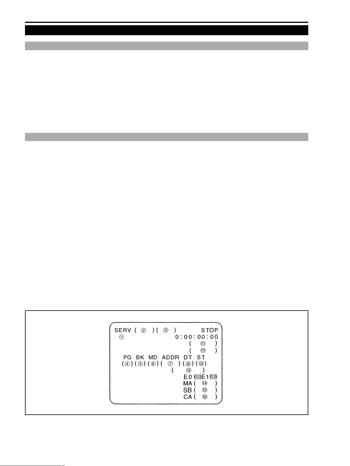
(1) The service mode of this product is the command-input-type service mode using the LANC communication.
(2) In the command-input-type service mode, the main unit can enter the normal operation modes using the keys of the
main unit. Also, when the HOLD SW is set back to the normal position, the main unit can be operated in the normal
operation modes from the service remote controller.
(3) In the command-input-type service mode, safety functions such as detection and protection of mechanism errors, dew
condensation detection and the safety system, low voltage detection and protection when the main power voltage is
decreased and others are disabled.
(4) In the command-input-type service mode, the LCD mirror function is disabled.
4-2 Service Mode Indications
On-screen indications in the service modes are shown as follows.
1 Indicates that the service mode is set up (“SERV”).
2 Indicates which block is subjected to the command (“MAIN”, “CAM”, “SUB” microcomputer etc.)
3 Indicates a message for special command (“DATA”, “SUB” etc.).
4 PG : Indicates the PAGE being selected (“4” to “7”).
5 BK : Indicates the BANK being selected (“0” to “7”).
6 MD : Indicates the MODE being selected (RD/WR).
7 ADDR : Indicates the ADDRESS being selected in hexadecimal (**00 to **FF, 0000 to FFFF).
8 DT : Indicates the DATA being read or set in hexadecimal (00 to FF).
9 DT : Indicates the DATA being read or set in binary (********), except for some special functions.
!0 ST : Indicates the STATUS in progress (“OK”, “NG”, “BUSY”, * etc.).
!1 Indicates an absolute track number.
!2 C0 : Indicates an error rate on a track traced by the CH0 (low channel) head.
!3 C1 : Indicates an error rate on a track traced by the CH1 (high channel) head.
!4 Indicates a version number of the MAIN microcomputer.
!5 Indicates a version number of the SUB microcomputer.
!6 Indicates a version number of the CAMERA microcomputer.
!7 Indicates the state of the mechanism. (“POPUP”, “STBY”, “LOAD1”, “LOAD2”, “STOP”, “PLAY”)
Fig. 3-3
3-6
Page 5
ZR10A
CHAPTER 3. INFORMATION FOR REPAIR • SERVICE HINTS
5. Description of Service Modes
5-1 Error Rate
<General>
(1) The video error rate (VIDEO + AUDIO) and the AUDIO error rate can be checked.
(2) Note that the error increases (error rate is worsened) when tape run is defective, tape is deteriorated, head output is
decreased, head amplifier is defective, drum shield is not appropriate.
<How to read the VIDEO error rate>
Average error rate of the video and audio sectors over the 64
tracks is indicated in exponential representation.
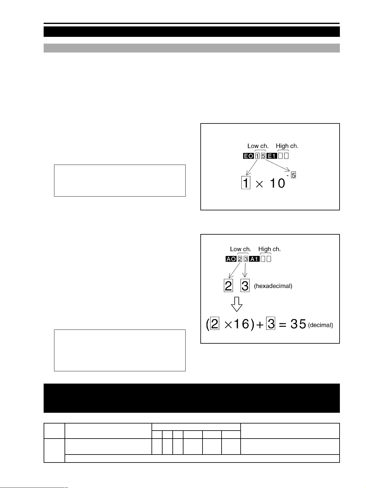
Example) When ‘15’ is indicated :
Error rate = 1×10
The product specifications requires that the error
rate on both channels by self-record/playback
in LP is as follows : Error rate = 2×10⁻⁵ or less
-5
Fig. 3-4
<How to read the AUDIO error rate>
To read error rate of AUDIO tracks, switch the display refer-
ring to the following table.
Number of sync blocks that contain error over the 64 tracks of
audio sync blocks is indicated in two hexadecimal digits.
(A maximum of 255 error blocks can be indicated by “FF”.
This is the limit and the number of error blocks more than that
is simply indicated by “FF”.)
Example) When ‘23’ is indicated :
Number of sync blocks containing error = 35
The product specifications requires that the error
rate on both channels by self-record/playback in
Fig. 3-5
LP is as follows : Error rate = 28H or less
(Number of sync blocks containing error = 40 or less)
Important
When the adjustment is complete, be sure to set the DT setup to the default setup of the product.
Press STORE key at the state of STEP 1 - PROCEDURE 1 as follows.)
STEP PROCEDURE MONITOR Microcomputer operation
ERROR RATE PG BK MD ADDR DT ST
1 1) Establish the setup as shown in the right. 6 4 WR --1D 00 Default setting.
2) Set DT to 03. ↑↑↑ ↑ 03 Audio error rate indication.
Reference) Default setting can be selected by resetting DT to 00. Thus, the Audio + Video error rate is indicated.
3-7
Page 6
ZR10A
CHAPTER 3. INFORMATION FOR REPAIR • SERVICE HINTS
5-2 Mechanical Error Indications
<Generals>
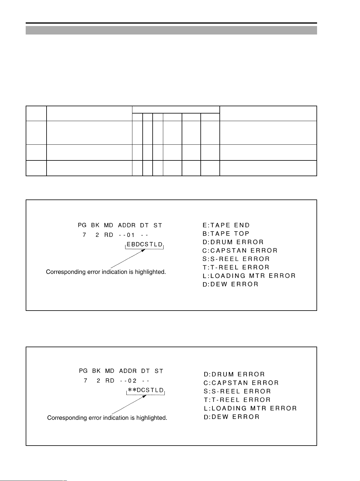
(1) When the camcoder is stopped as it detects a mechanical error, the POWER LED indicator blinks and the message
“EJECT CASSETTE” appears on screen. At this step, the error condition can be checked in the service mode.
(2) A mechanical error indication is given in either one of the following two manners : A group of mechanical errors
whose data is kept memorized only by the main battery and another group of mechanical errors whose data is backed
up by LITHIUM 3V. Referring to the table shown below, select the desired indication mode.
(3) Data backed up by the LITHIUM 3V can be reset at step 3.
STEP PROCEDURE MONITOR Microcomputer operation
MECH.ERROR PG BK MD ADDR DT ST
1 1) Establish the setup as shown in the right. 7 2 RD --01 -- Error data that can be kept memorized only
during the period of POWER-ON state is
indicated.
2 1) Establish the setup as shown in the right. 7 2 RD --02 -- Error data backed up by the EEPROM is
indicated.
3 1) Establish the setup as shown in the right. 7 2 WR --02 00
2) Press the STORE key. ↑↑RD ↑↑* Completion of resetting the backed-up data.
<Indications of mechanical errors whose data is kept memorized only by the main battery >
Fig. 3-6
<Indication of mechanical errors whose data is backed up by LITHIUM 3V >
Fig. 3-7
3-8
Page 7
CHAPTER 3. INFORMATION FOR REPAIR • SERVICE HINTS
5-3 Camera Special Commands
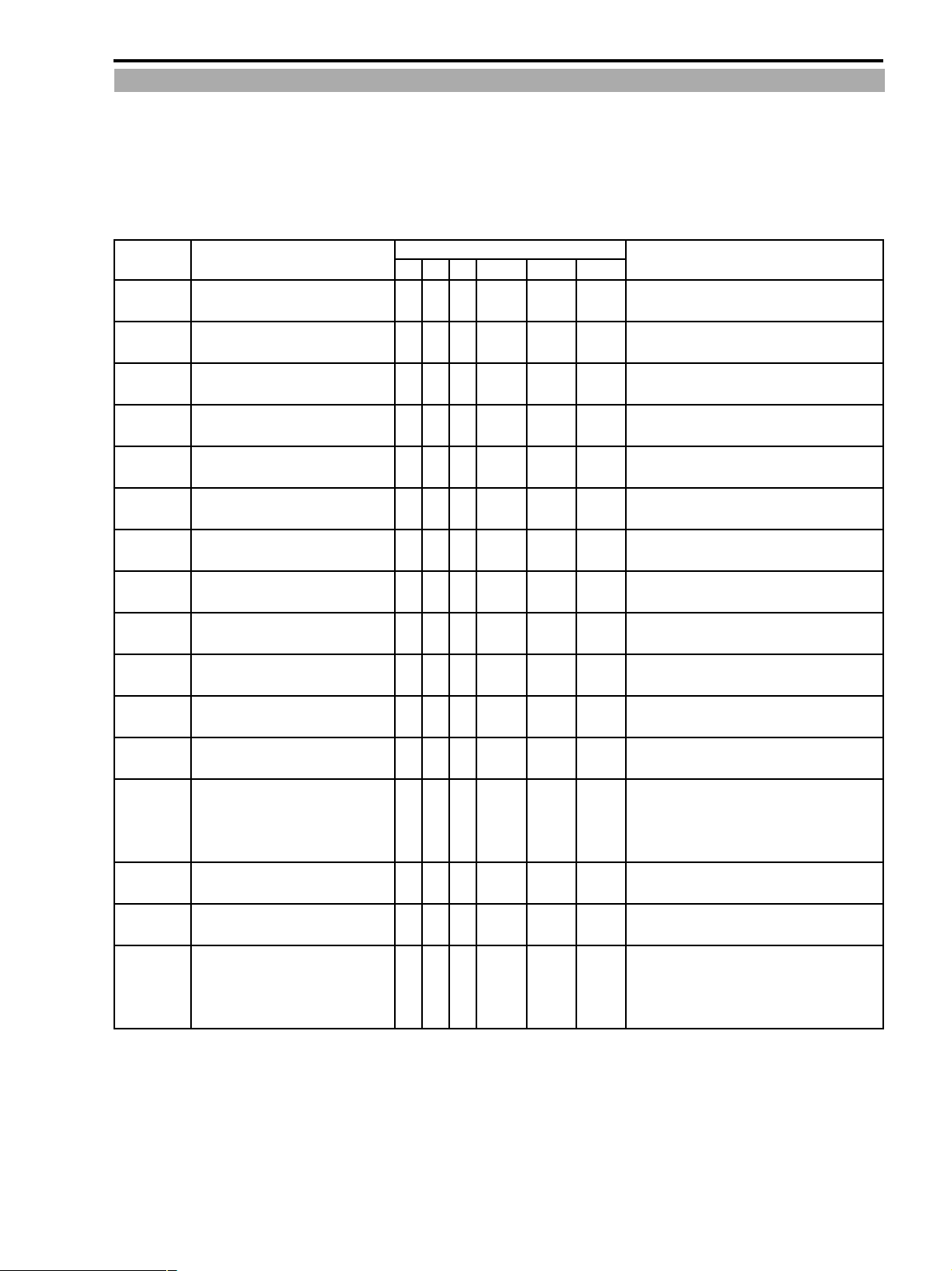
<Generals>
(1) The camera special commands are prepared for checking various operations of a camera.
(2) Referring to the table shown below, make preparation and use any camera special commands as required.
(3) Setting of each item can be reset when the STORE key is pressed in the “WR” mode.
Also all commands are reset by turning the main power off once and back on again.
STEP PROCEDURE MONITOR Microcomputer operation
CAM SPECIAL COMMAND PG BK MD ADDR DT ST
Preparation
WB SET
WB LOCK
WB TURBO
WB
OUTDOOR
WB
INDOOR
IRIS OPEN
IRIS CLOSE
AGC MAX
AGC MIN
White 100%
(DIC)
White 50%
(DIC)
White,
arbitrary
(DIC)
White 100%
(FIC)
White 50%
(FIC)
White,
arbitrary
(FIC)
1)
Establish the setup as shown in the right.
2) Press the STORE key.
1)
Establish the setup as shown in the right.
2) Press the STORE key.
1)
Establish the setup as shown in the right.
2) Press the STORE key.
1)
Establish the setup as shown in the right.
2) Press the STORE key.
1)
Establish the setup as shown in the right.
2) Press the STORE key.
1)
Establish the setup as shown in the right.
2) Press the STORE key.
1)
Establish the setup as shown in the right.
2) Press the STORE key.
1)
Establish the setup as shown in the right.
2) Press the STORE key.
1)
Establish the setup as shown in the right.
2) Press the STORE key.
1)
Establish the setup as shown in the right.
2) Press the STORE key.
1)
Establish the setup as shown in the right.
2) Press the STORE key.
1)
Establish the setup as shown in the right.
2) Press the STORE key.
1)
Establish the setup as shown in the right.
2) Press the STORE key.
1)
Establish the setup as shown in the right.
2) Press the STORE key.
1)
Establish the setup as shown in the right.
2) Press the STORE key.
1)
Establish the setup as shown in the right.
2) Press the STORE key.
5 3 WR **00 33 WAIT
↑↑RD ↑↑OK
5 2 WR 3300 -- WAIT
↑↑RD ↑ -- OK
5 2 WR 3301 -- WAIT
↑↑RD ↑ -- OK
5 2 WR 3302 -- WAIT
↑↑RD ↑ -- OK
5 2 WR 3303 -- WAIT
↑↑RD ↑ -- OK
5 2 WR 3304 -- WAIT
↑↑RD ↑ -- OK
5 2 WR 3305 -- WAIT
↑↑RD ↑ -- OK
5 2 WR 3306 -- WAIT
↑↑RD ↑ -- OK
5 2 WR 3307 -- WAIT
↑↑RD ↑ -- OK
5 2 WR 3308 -- WAIT
↑↑RD ↑ -- OK
5 2 WR 330A -- WAIT
↑↑RD ↑ -- OK
5 2 WR 330B -- WAIT
↑↑RD ↑ -- OK
5 2 WR 330C -- WAIT
↑↑RD ↑ -- OK
5 2 WR 330D -- WAIT
↑↑RD ↑ -- OK
5 2 WR 330E -- WAIT
↑↑RD ↑ -- OK
5 2 WR 330F -- WAIT
↑↑RD ↑ -- OK
Completion of setting at high address “33”.
WB is set.
WB is locked.
WB high-speed pull-in mode.
White balance outdoor mode.
White balance indoor mode.
The iris is opened forcibly.
The iris is closed forcibly.
AGC gain is set to its maximum value.
AGC gain is set to its minimum value.
Output a white 100% signal of DIC output.
Output a white 50% signal of DIC output.
White signal of DIC output (Brightness can be
changed as desired by changing DT of “PG : 5,
BK : 2, AD : 181C”.)
Output a white 100% signal of FIC output.
Output a white 50% signal of FIC output.
White signal of DIC output (Brightness can be
changed as desired by changing DT of “PG : 5,
BK : 2, AD : 181C”.)
ZR10A
3-9
Page 8
ZR10A
CHAPTER 3. INFORMATION FOR REPAIR • SERVICE HINTS
5-4 Checking The Lens Resetting
<Generals>
(1) Setting the address according to the table below allows to check whether the lens resetting has successfully ended or
not.
(2) The 1st digit of binary number indication (Fig. 3-4 9) of data is for zoom, and the 2nd is for focus resetting. Resetting
is ended when “1” is indicated.
STEP PROCEDURE MONITOR Microcomputer operation
LENS RESET PG BK MD ADDR DT ST
Preparation 1)
LENS RESET Set to status shown in the right and 5 2 RD 19F5 -- WAIT
Establish the setup as shown in the right.
2) Press the STORE key. ↑↑RD ↑↑OK Completion of setting at high address “1A”
check the binary number indication
data.
5 3 WR **00 19 WAIT
5-5 Operational Check of Control Keys and Switches
<Generals>
(1) Terminals of the MAIN and SUB microcomputers can be checked using the service mode. Thereby, it is allowed to
check key-related operations and key-microcomputer connections in the completely re-assembled product state.
(2) Addressees of the microcomputer terminals that can be checked with the service mode are shown in the ‘Remarks’
column in the I/O port table (p. 2-18 to p. 2-25). Note that since serial communication data signals are not synchro-
nous with the LANC communication cycle (field) in the service mode, operations related to these signals are not
indicated accurately. So, use indications for these signals just as reference data.
(3) The following explanations are provided for the data contents of terminals that seem rather complicated. For opera-
tional check of other key-related terminals than below, use the addresses shown in the ‘Remarks’ column of the I/O
port table and implement the operational checks.
(4) In order to perform the operational checks, select the RD mode.
5-5-1 Voltage range of A/D input key
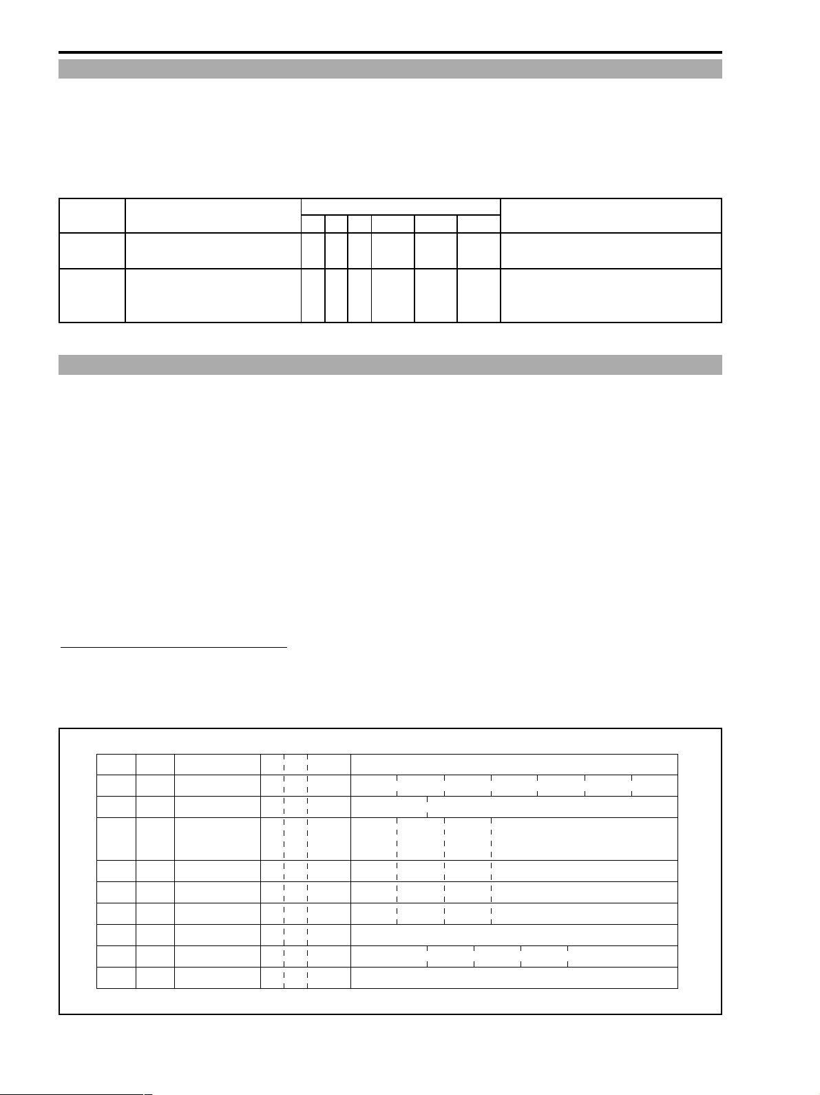
(1) The terminals that are shown in Fig. 3-8 are the analog voltage input keys of the MAIN and SUB microcomputers.
The key operations and the operational modes can be checked by detecting the A/D-converted voltages at the micro-
computer pins as shown in Fig. 3-8.
MI-COM
Pin No. NAME PG BK ADDR A/D DATA (00-FF)
MAIN 193 MSW AD 7 2 CA
MAIN 183 DEW DET 7 2 C0
MAIN 184 KEY A/D 0 7 2 C1
MAIN 185 KEY A/D 1 7 2 C2
MAIN 186 KEY A/D 2 7 2 C3
MAIN 187 KEY A/D 3 7 2 C4
SUB 40 CHARGE SENS 7 3 F2
SUB 41 BATT INFO A/D 7 3 F1
SUB 42 BATT A/D 7 3 F0
(00-36) (37-64) (65-87) (88-A2) (A3-BA) (BB-E3) (E4-FF)
LOAD1 STBY POP UP PLAY STOP LOAD2 GAP
(00-12) (16-FF)
DEW RELEASE DEW DET
(00-2C) (2D-67) (68-A7) (A8-FF)
ON/OFF DIGITAL MENU --
EXECUTE -- -- --
Charging current/voltage (unable to measure)
Voltage value of the main power
EFFECTS
PLAY FF -- --
STOP REW -- --
(DIAL)
(00-33) (34-65) (66-99) (9A-FF)
No battery -- BP-522 BP-511
Fig. 3-8
3-10
Page 9
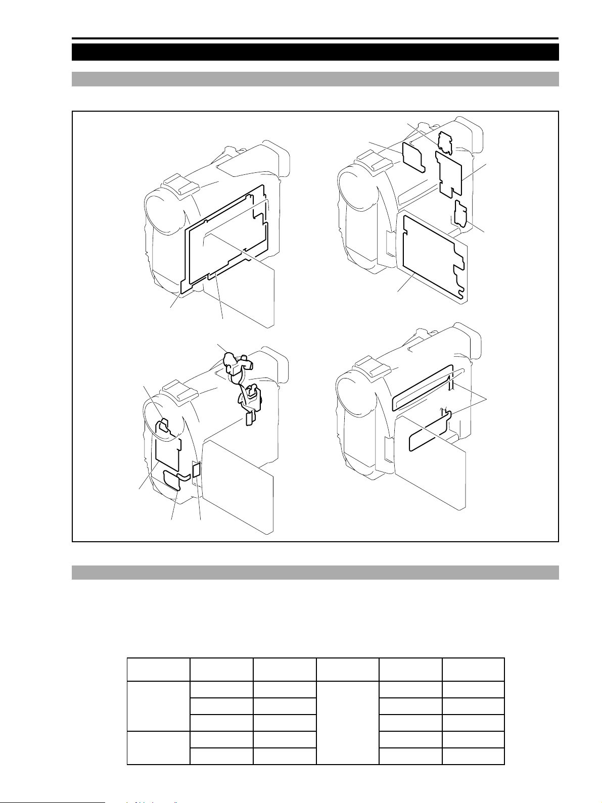
6. Service Hints
6-1 Circuit Board Layout
Layout of the printed circuit boards are shown below.
MAIN P.C.B.
PMCA P.C.B.
POWER KEY UNIT
ZR10A
CHAPTER 3. INFORMATION FOR REPAIR • SERVICE HINTS
CVF P.C.B.
CCD P.C.B.
LI P.C.B.
JOG P.C.B.
LCD P.C.B.
EJ P.C.B.
R-KEY FPC
JACK P.C.B.
SJ FPC DSW P.C.B
Fig. 3-9
6-2 Current Consumption Check
Actual measurement values of current consumption in each mode are shown in the following table.
Measurement condition : Completely re-assembled product status, camera auto mode (AF, IS OFF), LCD ON
(When CVF is used, current value becomes smaller by 0.1A in each mode.)
Power voltage : 7.4 V
POWER SW MODE
CAMERA REC PAUSE 0.56
REC 0.61
STOP 0.51
VTR STOP 0.44
PLAY 0.54
Current
consumption (A)
POWER SW MODE
VTR STILL 0.47
FF 0.70
REW 0.72
CUE/REV 0.59
Current
consumption (A)
3-11
Page 10

ZR10A
CHAPTER 3. INFORMATION FOR REPAIR • SERVICE HINTS
7. Troubleshooting
To detect the failure part for repair, if any, use the following hints and check points.
7-1 Power Supply
<Hints> :
When the main power is connected, the machine enters the standby mode in the following sequence.
Main power is connected. → POWER UNREG is supplied to the MAIN P.C.B. → SUB microcomputer starts up.→SUB
microcomputer establishes communication with MAIN microcomputer. → MAIN microcomputer initializes mechanism.
→ Enters the standby mode upon completion of initialization.
Then the power supply starts up in the following sequence.
Power mode switch is operated. → Upon receipt of command, SUB microcomputer outputs VTR ON “H” signal. →
PWM driver starts up and turns on each power supply. → Each microcomputer (SUB, MAIN, CAMERA) starts up to
implement system control.
<Check Points> :
1 Checking the key inputs
Check the key inputs at the POWER SW in the service mode.
2 Checking the microcomputer-to-microcomputer communications
Version number of each microcomputer appears in the service mode if microcomputer-microcomputer communica-
tion is normal. Otherwise, the communication line or microcomputer may be faulty.
3 Checking Errors in Mechanism (P. 3-8)
If initialization becomes faulty due to errors in mechanism, the error is detected.
Even if the mechanical error is detected, the main power can be turned on, but the machine enters the “ERROR STOP”
state. In this case, check the error data using the service mode.
4 Checking The Control Signal From SUB microcomputer VTR ON “H” Outputs
Check the output control signal using the LANC remote controller.
5 Checking Fuses
Check conduction of fuses FU3201, FU3202, FU3203 and FU3204. If any fuse is faulty, replace it and check the
current consumption.
6 Replace the PMCA P.C.B with a service part and check the operation.
3-12
Page 11

CHAPTER 3. INFORMATION FOR REPAIR • SERVICE HINTS
7-2 Camera Picture Faulty
<Hints> :
Flow of camera picture (EE) is shown below.
CCD → PMCA P.C.B. → MAIN P.C.B. (DIC IC → VIC → VIF) → JACK P.C.B.
<Check Points> :
1 Checking Lens Reset (P. 3-10)
If the camera picture does not appear at all, check that the lens is successfully reset using the service mode. If the lens
is not reset, check the lens.
2 Checking The Blue-Background Output Signal
The blue-background signal is generated by VIC on the MAIN P.C.B. in the VCR mode. When the blue-background
signal is confirmed to be output normally using the service mode, the signal line after VIC can be judged normal.
3 Checking The 100% White (FIC or DIC) Output Signal (P. 3-9)
The 100% white (FIC or DIC signal) signal is generated by DIC2S on the MAIN P.C.B. When the 100% white (FIC
or DIC signal) signal is confirmed to be output normally using the service mode, the signal line after DIC2S can be
judged normal.
4 CCD Output
The CCD output signal is sampled by the CDS/AGC/AD IC. Check this signal.
5 Checking with The Camera Special Command (P. 3-9)
Check operations such as white balance, AGC, IRIS control and others using the service mode.
ZR10A
7-3 Playback Picture Faulty
<Hints> :
In the DV format, deterioration of picture quality means that block noise appears on screen. This failure occurs when
errors occur exceeding capability of the error correction circuit occur so that the lacking picture information is compen-
sated by the picture information of the previous picture because the original picture information in block units cannot be
reproduced.
Normally, this failure occurs when error rate considerably increases due to deterioration of tape or decrease of head output
amplitude.
For this reason, be sure to evaluate the playback picture by measuring the error rate. Also, in order to evaluate the error
rate at an absolute value, use several kinds of tape.
<Check Points> :
1 Checking Deterioration of Tape
Check if scars, kinks, or the like are found on a magnetic surface of a tape or not. Compare it with the error rate of
other machines.
2 Error Rate (P. 3-7)
Check an error rate of the self-record/playback in LP picture using the service mode.
If the result shows that the error rate is poor, check the followings.
3 Checking Head Output (Refer to the DMCII Service Manual.)
Referring to the DMCII service manual, check the RF output amplitude and linearity. (Including cleaning of head)
Relation between amplitude of RF envelope waveform and the faulty symptom is as below.
• When amplitude of RF envelope at its entrance side is poor : Abnormal sound, block noise in the left part of screen.
• When amplitude of RF envelope at its exit side is poor : Defective timecode signal output, block noise in the right
part of screen and others.
4 Implementing The EQ Automatic Adjustment (P. 4-28)
Referring to the adjustment procedures, perform the EQ automatic adjustment. By this adjustment, the playback
amplifier in the VRP IC (on the MAIN P.C.B.) and the playback RF output are matched so that the adjustment to
minimize the error rate is performed automatically.
3-13
 Loading...