

Page 1
ZR10A
CHAPTER 1. GENERAL DESCRIPTION OF PRODUCT
1. Product Overview
• While maintaining the basic features, such as the 10X optical zoom, 2.5 inch LCD monitor, analog input, etc., these models were
designed aiming at considerable cost cuts in order to increase our share in the digital camcorder market by offering popular price
products.
• Despite being popular price models, their design has not been sacrificed for that purpose and they feature compaction being at the
same time stylish.
2. Main Features
(1) 10X optical zoom lens, 40X, 200X, digital zoom.
(2) Electronic stabilizer
(3) 1/4 inch CCD, total number of pixels : 460,000
(4) 2.5 inch, approx 112,000 pixels color LCD monitor (+color viewfinder)
(5) Digital input/output (DV terminal), analog input/output/audio dubbing function
(6) New compact lithium ion battery (Common for the OPTURA Pi)
(7) Main unit internal charging
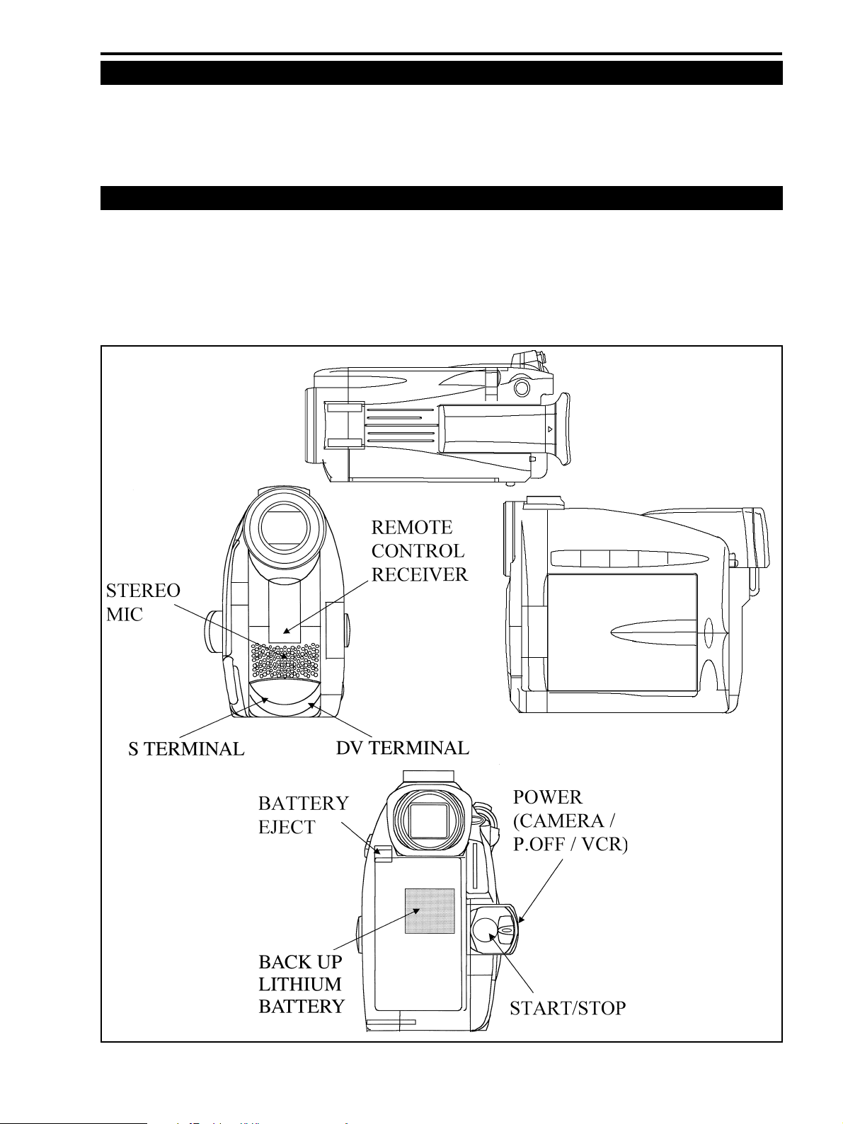
Fig. 1-1
1-3
Page 2
ZR10A
CHAPTER 1. GENERAL DESCRIPTION OF PRODUCT
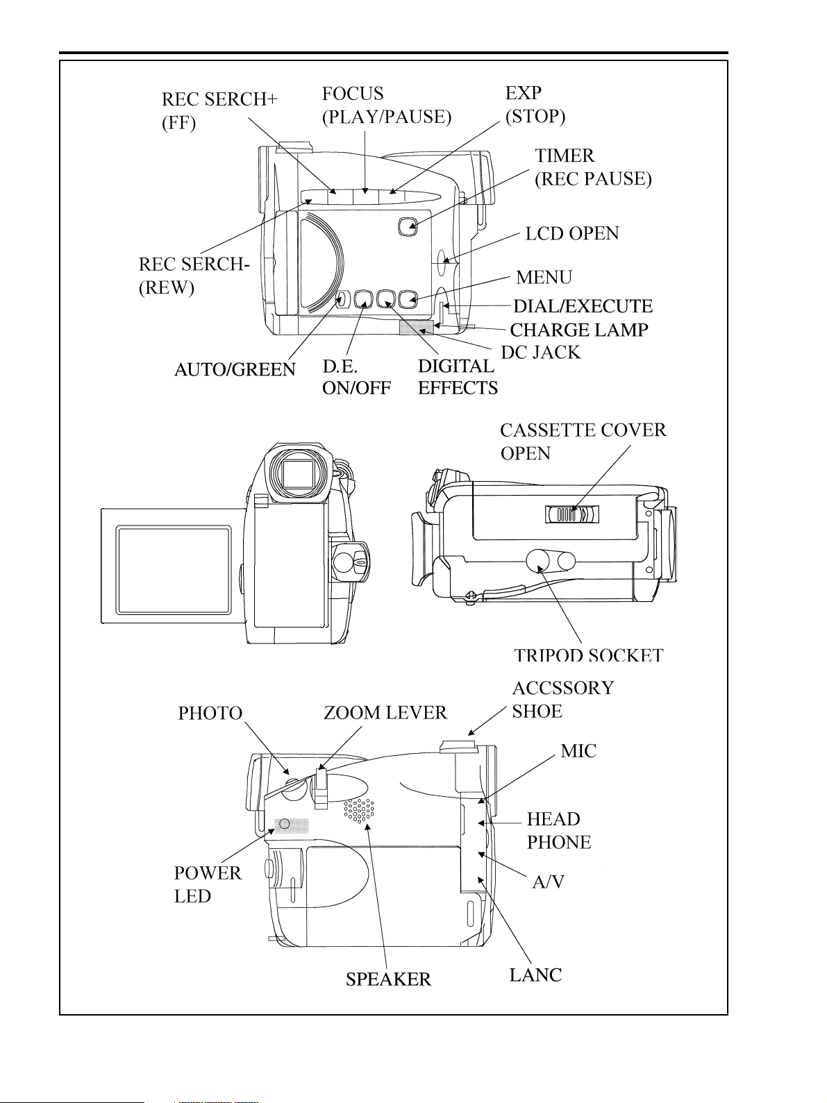
Fig. 1-2
1-4
Page 3
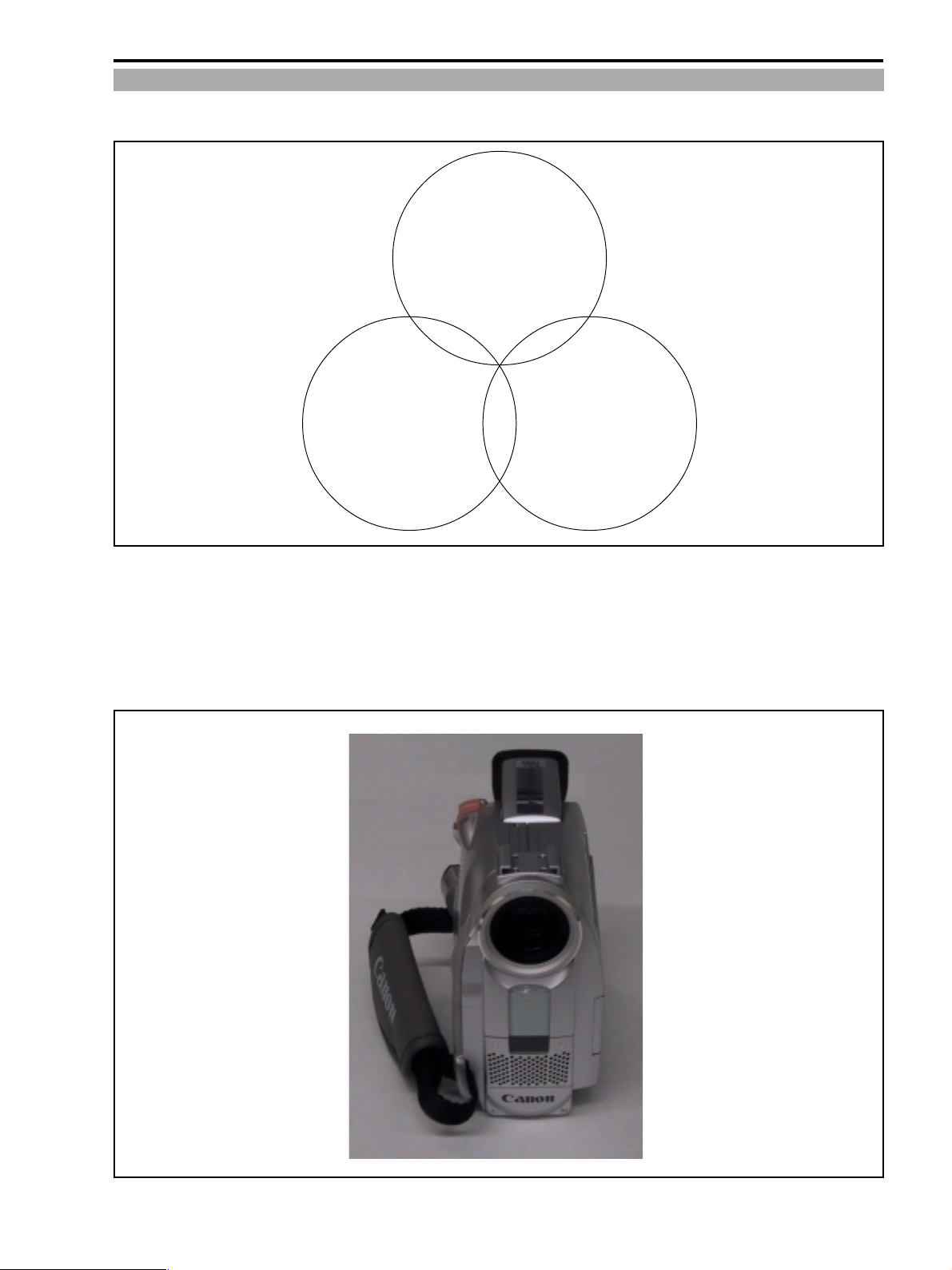
2-1 Designs
Stylish Concept
Traditional Frame
Modern Details
ZR10A
CHAPTER 1. GENERAL DESCRIPTION OF PRODUCT
Convenience
&
Operability
Traditional Frame
■ Slim & Right-to-Left Symmetrical Layout
■ Lens in the upper section, cassette in the lower section
■ Battery attached at the back
Long-time battery applicable
Fig. 1-3
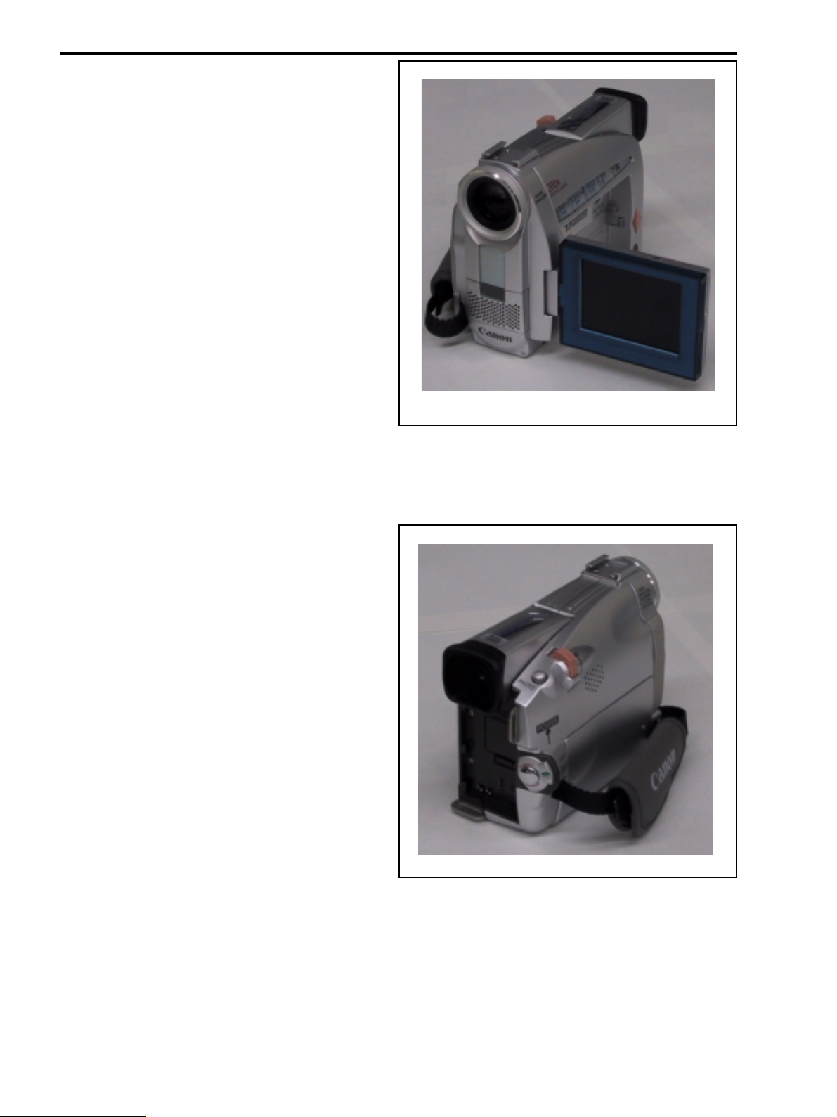
Fig. 1-4
1-5
Page 4
ZR10A
CHAPTER 1. GENERAL DESCRIPTION OF PRODUCT
Modern Details
■ Metallic & transparent material
Appeals to the new life style
■ Transparent material; affinity with personal computers, new
appearance
LCD periphery; Camera/Playback key; Remote Controller
Sensor
■ Metallic lock gives luxurious feel
• Filter Ring section : aluminum cut ring
• Movie trigger : chromium-plated
Convenience & Operability
■ Narrow grip allowing efficient use
■ Power Switch
On the same axle with the trigger, round cylinder layout
■ Consideration given based on the series of OPTURA,
OPTURA Pi, etc.
Fig. 1-5
1-6
Fig. 1-6
Page 5

ZR10A
CHAPTER 1. GENERAL DESCRIPTION OF PRODUCT
3. Performance and Functions
NTSC Models ZR10
1 Type Video Camcorder
2 Recording system Rotary 2-head helical scan azimuth recording Digital DVC for commercial use (SD specifica-
tions) In conformity to NTSC (525 lines, 60 fields)
2-1 Video signal recording system Digital component recording
Sampling frequency Y=13.5 MHz
R-Y, B-Y =3.375 MHz
Quantization bit number 8 bit
2-2 Audio signal recording system PCM digital recording
16 bit, 48 kHz, 2 channel
12 bit, 32 kHz, 4 channel (stereo 1)
2-3 Tracking 2-cycle pilot type
2-4 Tape speed Approx. 18.81 mm/s (SP mode)
Approx. 12.56 mm/s (LP mode)
2-5 Head drum
Drum diameter 21.7 mm
Rotation speed 9,000 rev./min.
Number of heads Video head : 2 pcs.
3 Recording/playback time Max. 120 minutes (on a 80 min. tape, for recording/playback in LP mode)
Continuous recording time When using the CVF : approx. 150 min.; when using the LCD monitor : approx. 120 min. (on
the BP-511) When using the CVF : approx. 310 min. ; when using the LCD monitor : approx.245
min. (on the BP-522)
4 Cassette tape used Mini DVC specifications
4-1 Tape type Vaporization type metal tape
4-2 Tape width 6.35 mm
4-3 Tape thickness 7µm
5 Camera
5-1 Imaging device 1/4 inch interlace CCD
5-1-1 Number of pixels Total number of pixels : approx. 460,000; number of effective pixels : 290,000
5-1-2 Filter Mosaic complementary color filter
5-1-3 Color separation system Differential signal obtained by mixturing the pixels are synchronized to generate the RGB
signals.
5-1-4 Signal configuration NTSC standard color video signal
5-1-5 Scan system 525 lines, 60 fields/30 frames
5-1-6 Minimum subject illumination Approx. 2.5 lux (in the low light mode)
Approx. 2.5 lux (in the low light mode)
Approx 10 lux (in the auto mode)
5-1-7 Subject illumination range Approx. 2.5 lux to approx. 100,000 lux
5-2 Lens
5-2-1 Nominal focal length 4.2 to 42 mm
Zoom ratio 10X (optical lens); electronic zoom 40X (10×4=40); 200X (10×20=200)
(35 mm film converted) 48 mm to 480 mm ; 1,920 mm (equivalent) to 9,600 (equivalent)
5-2-2 Nominal aperture ratio 1 : 1.8 (F2.9 at TELE)
5-2-3 Lens configuration 7 groups, 10 elements, using 2 aspherical lenses
5-2-4 Focusing Inner focus type/manually adjustable (with the FF/REW seesaw switch)
5-2-5 Minimum shooting distance 10 mm (AF linkage : WIDE); 1 m in the entire zoom range (from the lens surface)
5-2-6 Power zoom Multi-step variable speed power zoom. Rotation lever. Zooming speed can be changed with
the rotation angle of the lever. Approx. 40 sec. to approx. 3 (3.2) sec. (optical zoom) Approx.
44 sec. to approx. 4.5 (4.6) sec. (when using the digital zoom) No manual zooming (no zoom
ring).
5-2-7 Focal distance indication None. Simple shape indication of the zooming status shown in the finder.
5-2-8 Macro mechanism WIDE macro
5-2-9 Macro shooting distance 10 mm (from the lens surface)
5-2-10 Filter diameter Provided. 30.5 mm, P=0.5 mm ; 46 mm dia. filter or accessory lens can be attached after
installing the optional SR-30.5/46 step up ring.
5-2-11 Accessory lens Attachable. 46 mm dia. filter or accessory lens can be attached after installing the optional SR-
30.5/46 step up ring.
1-7
Page 6
ZR10A
CHAPTER 1. GENERAL DESCRIPTION OF PRODUCT
5-2-12 Lens hood None
5-2-13 Lens cap Provided. Covering type.
5-3 Stabilizer Provided
5-3-1 System Electronic stabilizer
5-3-2 Hand jitter detection system Angular velocity detection
5-4 Shooting modes Motion picture mode and photo shooting mode
5-4-1 Movie mode Normal recording
5-4-2 Photo mode Approx. 6.5 sec. still picture recording LOCK indication appears when pressing the Start/Stop
button halfway within the finder ( : when the AF is locked, lights in green).
5-5 Exposure control
5-5-1 Photometric method Center-lower-weighted average photometry : Full Auto mode, Auto mode, Sports mode, Por-
trait mode, Low light mode Full screen average photometry +64 section evaluation photom-
etry : Spotlight mode, Surf (sand) & Snow mode
Screen division 64 sections (8V×8H)
5-5-2 AE function
Program AE Full auto mode, Auto mode, Sports mode, Portrait mode, Spotlight mode, Surf (sand) & Snow
mode, Low light mode
5-5-3 Exposure compensation function
EXP Lock EXP Lock by pressing the exposure button. Exposure compensation adjustable with the multidial
after executing EXP lock (except for the Full Auto mode).
Compensation range ±11 levels (±2.75 EV), 0.25 aperture per 1 step, with bar ( ) indication in
the finder.
5-5-4 Electronic shutter
High speed shutter 1/60 sec., 1/100 sec., 1/250 sec., 1/500 sec., 1/1000 sec., 1/2000 sec., 1/4000 sec... 1/8000 sec.
(in the auto mode)
Low speed shutter 1/15 sec. (in the low light mode : fixed speed)
5-6 AF (Auto Focus)
5-6-1 Type TTL video signal detection type AF.
5-6-2 AF measurement frame indication Screen center
5-6-3 Measurement area None.
5-6-4 AF operational range 10 mm - ∞ (WIDE); the entire zoom range : 1 m - ∞ (from the lens surface)
5-6-5 AF operational illumination range 50 lux to 100,000 lux
5-6-6 AF mode selection Continuous AF / manual focus. AF ON/OFF selection available except for the Full Auto mode
(by pressing the focus button).
Manual focus Manual focus available by rotating the multidial ring (when in the manual focus mode). When
in the manual focus mode (AF is off), “M. Focus” appears in the finder.
5-7 Viewfinder 0.44 inch color LCD (approx. 113,000 pixels); fixed length. Turned off in all modes except for
the case when the LCD monitor is closed in its storage position (with the panel facing the main
unit).
Rotation Possible (up 70° : applicable for low angle)
Eyepiece removing Impossible.
Visibility adjustment range +1.0 to -5.0 diopters (when looking through the viewfinder)
Lens configuration 1 group, 1 element
5-8 LCD panel 2.5 inch color LCD, 112,000 pixels [480 (H)×234 (V)]; TFT active matrix drive. RGB delta
array. Turned on in all modes except for the case when the monitor is closed in its storage
position (with the panel facing the main unit).
Angle adjustment Possible. High angle, low angle. also monitoring available in the self-shooting mode.
Information display Operation modes, simple zoom position, battery status, tape status, time code, various warn-
ings, color indications. The indications are limited while in the self-shooting mode.
1-8
Page 7
CHAPTER 1. GENERAL DESCRIPTION OF PRODUCT
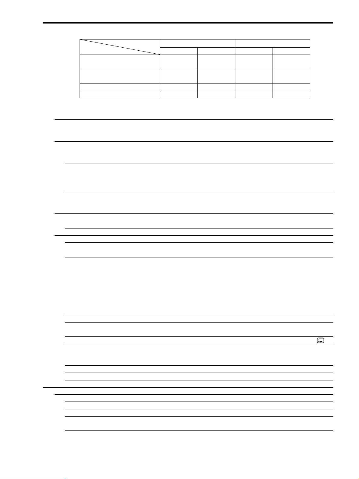
Relation with the viewfinder (EVF)
Camera Mode VTR Mode
LCD Panel Positioning LCD Panel EVF LCD Panel EVF
With the panel closed OFF ON OFF ON
(the panel surface facing the main body)
With the panel closed ON OFF ON OFF
(the panel surface facing outside)
With the panel opened ON OFF ON OFF
In the self-shooting mode* ON*1 ON ON OFF
*1 : Can be set as a mirror in the menu.
In the mirror mode (when in the recording search, etc. playback screen output, the mirror mode is temporarily canceled.)
5-9 White balance adjustment TTL 64-section with the new white extraction type FAWB. With the Set, Preset (outdoors :
5,600K ; indoors : 3,200K) features (selection in the camera menu).
Adjustment range 2,800 K to 8,000K
5-10 Digital features There are such modes as fading and effects. Fading : When combining with the Start/Stop
button, can be once executed while the fading mode indication is on (the mode indication
disappears after fading is completed). Effects : Remain on until turning them off.
5-10-1 Fader Operable only in the movie mode (cannot be executed in the photo mode). Fading simulta-
neously with sound. Auto fading (domestic model : white fading ; overseas model : black
fading), vertical wipe. horizontal wipe, mosaic fading.
Fading time Approx. 4 sec.
5-10-2 Effects Art, black&white, sepia, mosaic. The mode indications appear while executing the effects ;
when the mode indications blink, it means that the effects are off. The effect functions are
toggled on/off by pressing the D.E. ON/OFF button.
5-11 Internal microphone Stereo microphone (electret condenser microphone) Omnidirectional microphone ×2+stereo
via an electronic circuit
5-11-1 Wind reduction function Provided. With an ON/OFF switch (menu selection ; for the internal microphone only)
5-12 Additional functions
5-12-1 Time code The recording time (0 : 00 : 00-7 : 59 : 59 : 59) is being displayed, recorded in the sub-code
area.
5-12-2 Data code Not displayed in the recording mode, however the date and the camera information are re-
corded and can be displayed during playback.
Time & date Period covered : January 1, 2000 to December 31, 2050 (factory preset to January 1, 2000).
World clock (by selecting cities names while traveling, appropriate date and time are set auto-
matically ; summer time). 3 display modes can be displayed while playing back : date, date &
time, or time (covered range : January 1, 1990 to December 31,2089).
Camcorder information Recording the shutter speed, aperture value (no display while recording), can be displayed
while playing back.
5-12-3 Accessory shoe Provided
5-12-4 Recording search function Available. While in the recording pause mode, it is possible to check the picture by playing the
tape forward/reverse using the recording search buttons.
5-12-5 Recording review function Available. While in the recording pause mode, operate the recording check button ( ).
5-12-6 Zero set memory Available. It is possible to fast forward or rewind the tape to the point where the zero set
memory key of the WL-D74 was pressed (the counter is set to 0 : 00 : 00) (when recording only
zero setting is available. This function can be used in the playback mode).
5-12-7 Remote control on/off Available. Possible during shooting, in the VCR mode (menu selection).
5-12-8 Self timer Available. 10 sec. Note : 2 sec. possible while operating with WL-D74 wireless controller.
5-12-9 Headphone volume Adjustable by multi dial.
6 Recorder
6-1 Recording function Camera recording, DV input recording, analog-in recording
6-1-1 Recording format Digital DVC for commercial use (SD specifications)
6-1-2 Tape speed Approx. 18.81 mm/s (SP mode); approx.12.56 mm/s (LP mode)
6-1-3 DV input recording In confirmity to IEEE1394
Recording of video and audio signals from a digital video camera connected with a DV cable
6-1-4 Analog input recording Recording of video and audio analog signals through the S-video terminal or audio/video mini
terminals.
ZR10A
1-9
Page 8

ZR10A
CHAPTER 1. GENERAL DESCRIPTION OF PRODUCT
6-1-5 Priority order of terminals DV terminal > S-video terminal >
while recording AV mini terminals
6-2 Insert recording Possible.
6-2-1 Insert recording applicable tape With a tape for SP recording only.
6-3 Audio dubbing Possible.
6-3-1 Audio dubbing applicable tape With a tape for 12 bit SP recording only. except for 4 channel simultaneous recording
6-3-2 Audio dubbing signal input Line (AV mini terminal) or microphone (external > built-in) audio signal
6-3-3 Switching to audio dubbing With the audio dubbing button on the remote controller in paused playback mode
6-4 Playback functions Standard playback and special playback
6-4-1 Standard playback
a. Video Playback of video recorded on SP or LP mode
b. Audio 16 bit For frequency sampling of 48 kHz, 44.1kHz, 32 kHz
12 bit For frequency sampling of 32 kHz Playback in stereo 1, stereo 2, or a mixed stereo 1 and 2
mode (mixing ratio adjustable).
6-4-2 Special playback Video only (SP, LP mode)
a. Still picture Frame still
b. FF playback Approx. 9.5x normal speed
c. REW playback Approx. 9.5x normal speed
d. Frame-by-frame playback Both direction frame-by-frame playback
e. Slow playback Both direction at 1/5 normal speed ; both directions at 1/10 normal speed
f. 1x normal speed playback Normal speed in both directions
g. 2x normal speed playback Double speed in both directions
h. Edit search Normal speed in both directions
6-5 Tape FF/REW time Approx. 2 min. 30 sec. (on a 60 min. tape)
6-6 Input signal
6-6-1 DV terminal In conformity to the IEEE1394-AV/C protocol
6-6-2 Microphone terminal 3.5 mm dia. stereo minijack
Impedance 5 kΩ or more
Level -61 dBv (when using a 600Ω microphone)
6-7 Output signal
6-7-1 DV terminal In conformity to the IEEE1394-AV/C protocol
6-7-2 Video /audio terminals 3.5 mm dia. 4-pole minijack
a. Video signal
Signal configuration NTSC standard color video signal
Impedance 75Ω
Signal level 1 Vp-p (composite)
b. Audio signal
Signal type Stereo audio signal
AV mini terminal Headphones terminal
Output impedance 3kΩ or less 150Ω
Output signal level -10dBv (at 47 kΩ load) With the maximum volume
(at 47 kΩ load) volume : -25 dBv (at 16 Ω load)
Frequency characteristics 60Hz to 16 kHz (a range of 1 kHz standard ±3dB)
Audio signal S/N
With the microphone input 48 dB or more
With the external microphone input 48 dB or more
6-7-3 S-video terminal
Signal configuration NTSC Y/C separated video signal
Video signal 1 Vp-p (brightness + sync signal)
Color signal 0.286 Vp-p (color burst signal)
Brightness signal S/N 45dB or more
1-10
Page 9
CHAPTER 1. GENERAL DESCRIPTION OF PRODUCT
6-8 Other functions
6-8-1 Inter-scene shooting, mechanism Possible between scenes after recording pause, stop mode, or switching power off, except
cassette ejection.
6-8-2 Automatic stop mechanism Activates when the playback pause mode continues for approx. 5 min., when the dew conden-
sation warning appears, or when the tape reaches the end or beginning.
6-8-3 Automatic power off mechanism Activates when the recording pause continues for approx. 5 min., or when the battery voltage
drops below the specified level.
6-8-4 Time code Automatic recording in the recording mode. 0 : 00 : 00 : 00-7 : 59 : 59 : 29
(hr : min. : sec. : frame)
6-8-5 Photo search Mode for searching for images taken in the photo mode. Photo searching in both directions
(operation with the , keys after choosing photo-search with the search select key on the
remote controller) Possible to set to the ±10th position from the current position.
6-8-6 Date search In case of a multiple day of recording, the unit searches for the point where the date changed.
Reverse date search (operation with the , keys after choosing date search with the search
select key on the remote controller) Possible to set to the ±10th position from the current
position.
6-8-7 World clock display After having set a standard city (the city for which the clock time is set), when selecting a city
name where shooting is carried out, the unit automatically switches to that local date and time
and records the date code.
6-8-8 Speaker Built-in. With volume adjustment.
6-8-9 Battery charging function When using the Canon Compact Power Adapter CA-560, the battery pack attached to the
battery pack slot can be charged (when the main unit power switch is off, or in the VCR stop
mode).
Charging indication 1 blink (up to approx. 50% charged), 2 blinks (approx. 50% to 75% charged), 3 blinks (up to
approx. 90% charged), continuously on (90% or more charged). Abnormality alert : blinking
(0.2 sec. period)
Charging current 1.2A DC
Charging time (continuous charging) Approx. 95 min. (with the BP-511), approx. 155 min. (with the BP-522) until the charging
complete indication.
7 Terminals
7-1 DV terminal Special 4-pin terminal (in conformity to IEEE 1394), input/output combined
7-2 S-video signal terminal 4-pin mini DIN, input/output combined
7-3 Video/audio terminal 3.5 mm dia. 4-pole pin jack (yellow), input/output combined
7-4 External microphone input terminal 3.5 mm dia. stereo minijack (red)
7-5 Headphone terminal 3.5 mm dia. stereo minijack (green)
7-6 Edit terminal 2.5 mm dia. mini minijack, for LANC
7-7 Battery terminal 2 terminals
7-8 DC power input terminal Special multi terminal (9.5 V DC)
8 Power supply
8-1 Power supply voltage 7.4 V DC (battery pack), 9.5 V DC (DC IN)
8-2 Power consumption
During recording : (with AF) Approx. 3.7 W (when using the CVF),
approx. 4.6 W (when using the LCD monitor )
9 Dimensions (W×H×D) Approx. 57×101×129 mm
(small projecting parts excluded) (Approx. 2 1/4×4×5 1/8 in.)
10 Weight
10-1Main body Approx. 550 g (approx. 1lb 3 3/8 oz)
10-2 When ready for use Approx. 645 g (approx. 1lb 6 3/4 oz) (Including BP-511, DVM-E30, lens cap, button type
lithium battery)
11 Operating environment
11-1 Guaranteed performance conditions 0°C to +40°C 85% RH
11-2 Guaranteed operation conditions -5°C to +45°C 60% RH
ZR10A
1-11
Page 10
ZR10A
CHAPTER 1. GENERAL DESCRIPTION OF PRODUCT
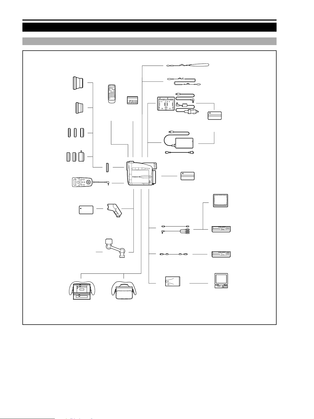
4. System Chart
4-1 NTSC Model
WS-20 Wrist Strap
WD-46 Wideconverter
TL-46 Teleconverter
FS-46U
Filter Set
FS-46
Filter Set
ZR-1000 Zoom
Remote Controller
BP-900 Series
Battery Pack
WL-D74
Wireless
Controller
SR-30.5/46
Step-up Ring
VL-10Li
Battery
Video Light
MiniDV
Video
Cassette
SS-600 Shoulder Strap
CR-560 Charge Adapter/
Car Battery Cable Kit
CA-560 Compact
Power Adapter
S-150 S-video Cable
STV-250 Stereo Video Cable
BP-500 Series
Battery Pack
BP-500 Series
Battery Pack
TV
VCR
Stereo Microphone
(commercially
available)
SC-1000 Soft
Carrying Case
MB-100
Microphone Boom
SC-A50 Soft
Carrying Case
Fig. 1-7
CV-150F DV Cable
FR-100 Floppy Disk
Still Image Recorder
Digital Device
Personal Computer
1-12
Page 11
CHAPTER 1. GENERAL DESCRIPTION OF PRODUCT
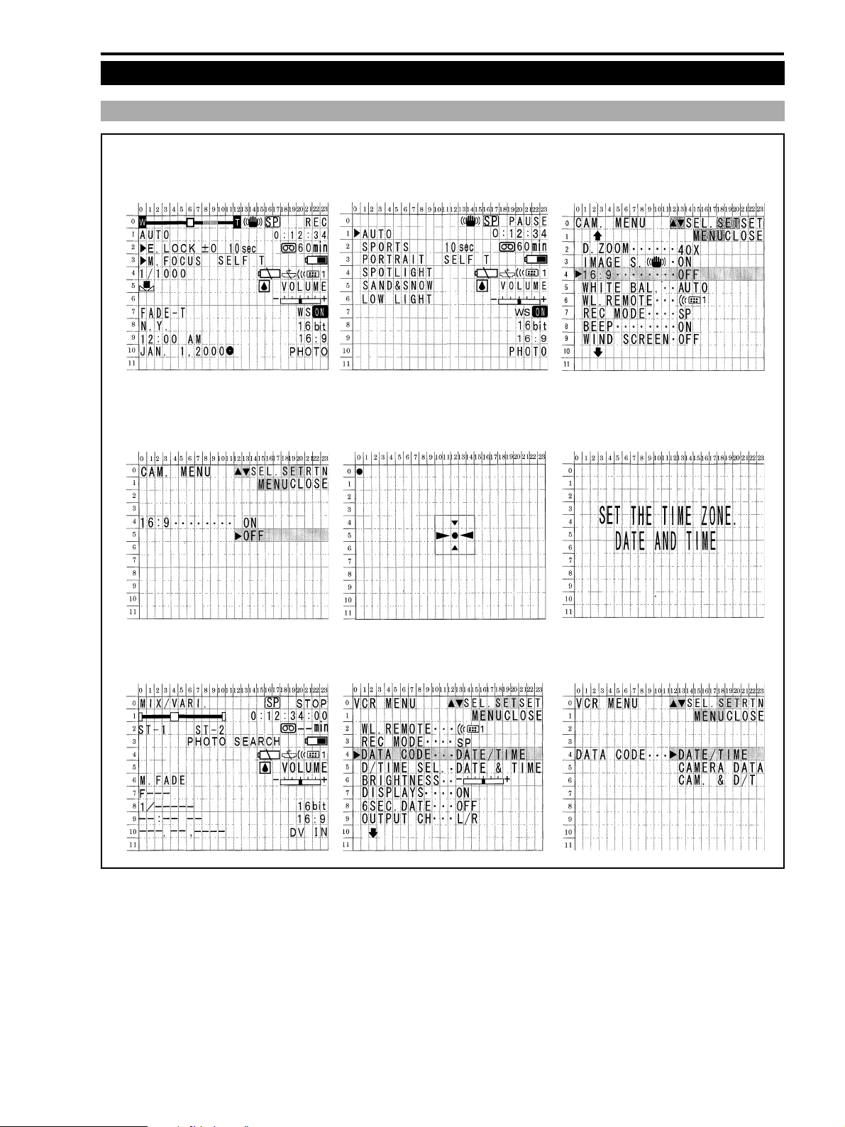
5 Finder/LCD Panel Indications
5-1 NTSC Model
Camera shooting mode Camera program AE menu Camera menu screen
Camera menu selection Camera self-shooting mode Warning
(in the mirror mode, LCD panel)
ZR10A
VCR mode VCR menu screen While selecting in the VCR menu
Fig. 1-8
1-13
Page 12
ZR10A
CHAPTER 1. GENERAL DESCRIPTION OF PRODUCT
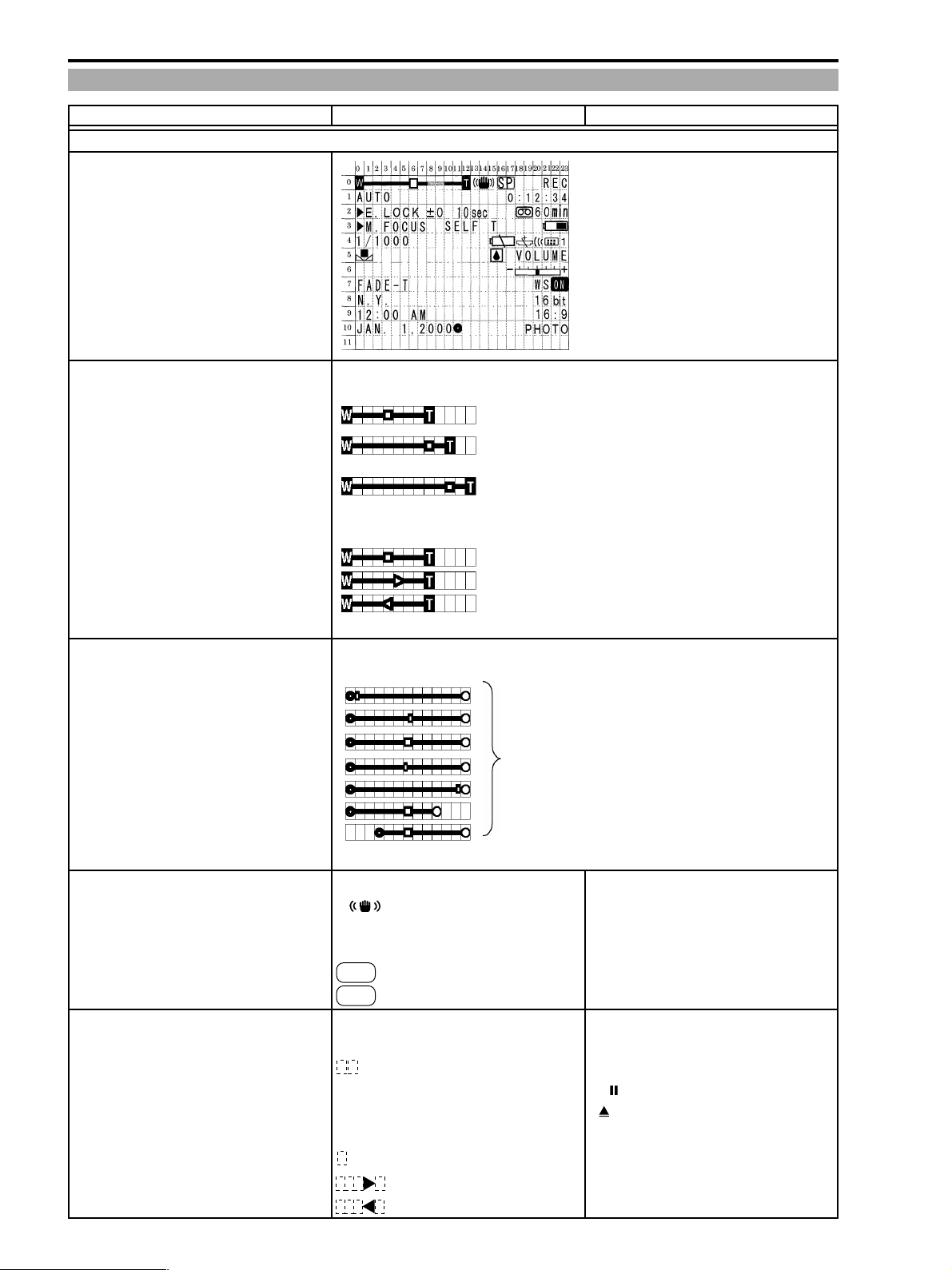
5-2 List of the Finder/LCD Panel Indications
Menu indication NTSC Model Remarks
1 : Camera Mode
Zoom indications (displayed for approx.
4 sec. after zooming)
With the optical zoom
With the 40X digital zoom Displayed in sky blue when in the
range of over 11x
With the 200X digital zoom Displayed in blue when in the range of
over 41x
Zoom stopped
Zooming towards TELE
Zooming towards WIDE
Exposure compensation indications
AE No indication
Minimum exposure-11 levels
Preset exposure Multidial operation after executing
EXP lock
Maximum exposure +11 levels
Indicated by exposure variable range
indication
Stabilizer indications
Stabilizer on
Stabilizer off No indication
Tape speed indications
SP mode selected
LP mode selected LP
Operation mode indications With the self shooting mirror mode set
SP
(LCD)
Recording REC Green indication ●
Recording pause PAUSE Green indication ●
When removing the cassette EJECT Green indication, flashes
in red when error occurs.
Stop STOP Green indication
+ Rec Search Green indication
- Rec Search Green indication
1-14
Page 13
CHAPTER 1. GENERAL DESCRIPTION OF PRODUCT
Menu indication NTSC Model Remarks
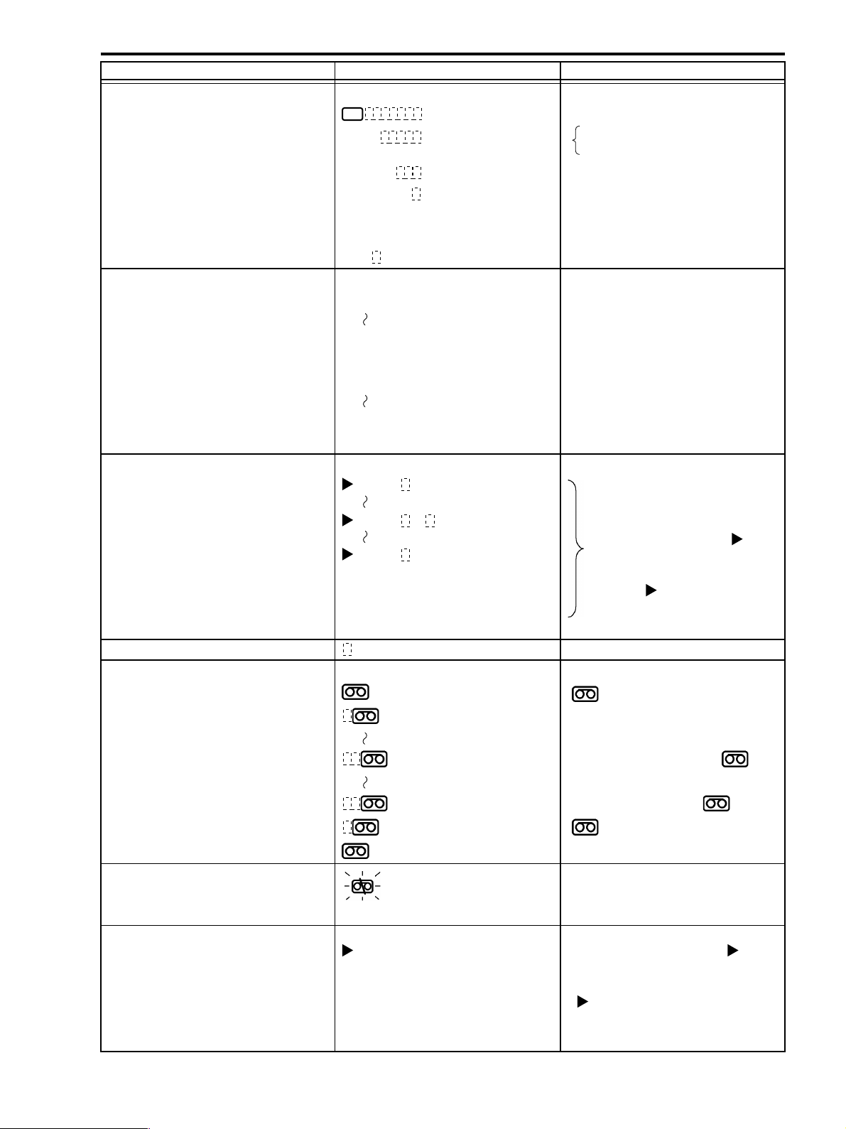
Program AE Mode Indications
Full Auto mode selected Green indication
Auto mode selected AUTO
Sports mode selected SPORTS
Portrait mode selected
Spotlight mode selected
Sand & Snow mode selected SAND & SNOW
Low light mode selected LOW LIGHT
Tape Counter
Time code indication (no frame indication)
Undetermined – : - - : - -
Memory set to zero. 0 : 00 : 00M
Undetermined – : - - : - - M
AE Lock indications In the EXP lock
Exposure minimal value
AE lock
Exposure maximal value
AE No indication
Alarm timer indications 0 sec-10 sec
Remaining tape indicator
PORTRAIT
SPOTLIGHT
0 : 00 : 00
7 : 59 : 59
7 : 59 : 59M
E.LOCK -11 * The digits blink when in the minimal
E.LOCK ±0 per 1 step. When exposure
E.LOCK +11 “blue” characters are displayed.
255 min
99 min
Displayed for approx. 4 sec. after
switching, exiting the menu.
or maximal exposure. 0.25 aperture
compensation is possible, “
When exposure compensation is not
possible, “
are displayed.
mark - green ; Time is displayed
in 1 minute units.
ZR10A
” +
” + “white” characters
5 min Less than 5 minutes : yellow
mark
0 min Less than 1 minutes : red mark
Tape end
Undetermined – –min
Tape warnings Erasure protection tap set to on :
Other No indication
Focus mode indications Except for the Full Auto mode When
AF off M. Focus focus adjustment is possible, “ ”+
AF on No indication
END mark and END red indication min
indication blinking in red
“blue” characters are displayed.
When focus adjustment is not possible,
“
”+ “white” characters are dis
played.
1-15
Page 14
ZR10A
CHAPTER 1. GENERAL DESCRIPTION OF PRODUCT
Menu indication NTSC Model Remarks
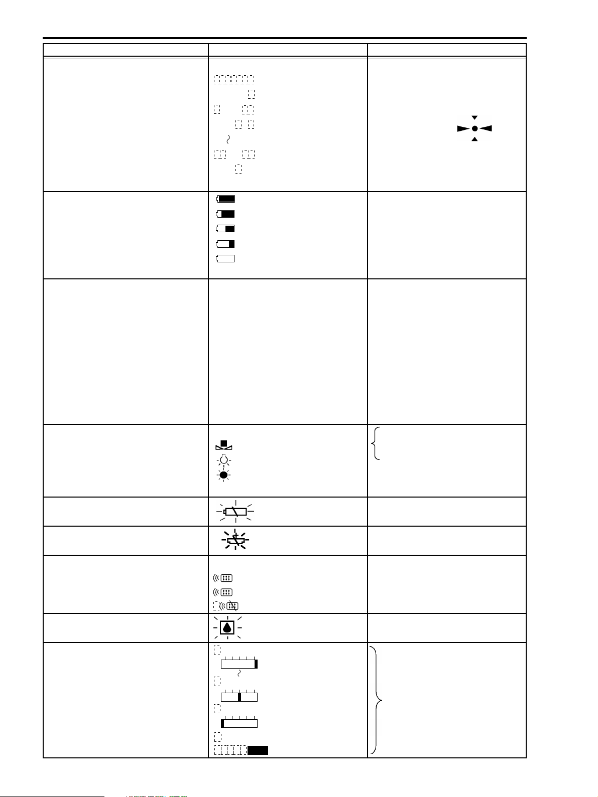
Self timer indications
Timer standing-by
SELF-T
Timer activated
SELF
SELF
Other No indication
Battery status Approx. 100% power left
With the power adapter attached No indication
Shutter speed indications
1/60 sec. 1/60
1/100 sec. 1/100
1/250 sec. 1/250
1/500 sec. 1/500
1/1000 sec. 1/1000
1/2000 sec. 1/2000
1/4000 sec. 1/4000
1/8000 sec. 1/8000
Auto mode No indication
White Balance Indications Blinks when setting white balance and
Setting
Outdoors preset
Indoors preset
Auto No indication
Battery warning Indication blinking in red
10
sec
T
1
sec
T.
In the self shooting mode shown in the
LCD panel indication only.
The indication blinks during count
down.
Approx. 75% power left
Approx. 50% power left
Approx. 25% power left
Approx. 0% power left
NG. Lights up continuously after
the mode setting completed.
Button lithium battery low warning Indication blinking in red
indication
Remote controller code indications
Code setting, selection 1
Code setting, selection 2
Remote control signal reception off
Dew condensation warning Indication blinking in red
Volume indications
1
2
VOLUME
+–
VOLUME
+–
VOLUME
Indicated for approx. 4 sec. after
adjustment. Indicated in 15 levels
+–
VOLUME
OFF
1-16
Page 15
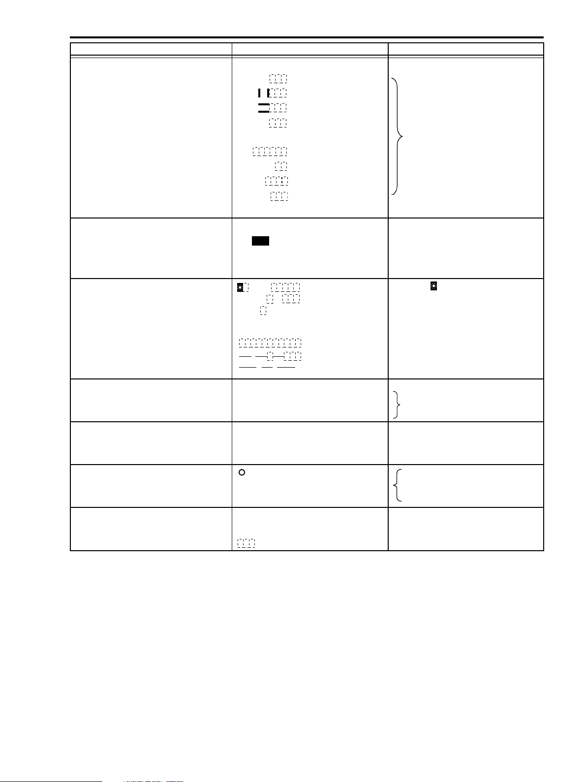
ZR10A
CHAPTER 1. GENERAL DESCRIPTION OF PRODUCT
Menu indication NTSC Model Remarks
Digital feature indications
Auto fading selected FADE-T
Horizontal wipe selected
Vertical wipe selected
Mosaic fading selected M.
Art selected
Black & White selected
Sepia selected
Mosaic selected
Effects off No indication
Wind screen indication
Wind screen feature ON
Wind screen feature OFF No indication
With the external microphone connected
Date & time indication Area and are indicated for approx.
WIPE
WIPE
FADE
ART
BLK&WHT
SEPIA
MOSAIC
WS ON
N. Y.
12 :00
JAN. 1.2000
AM
No indication when the digital feature
effects are turned off. The indications
are blinking in the stand-by mode
and light up steadily in executing.
4 sec.
Date & time not set
:
..
Audio mode indications
16 bit selected 16 bit Displayed approx. 4 sec. after the
12 bit selected 12 bit
16 : 9 mode indications
16 : 9 mode selected 16 : 9
Other No indication
Half-button lock indications
(when operating the photo button) operation. Indicated in green after
Movie picture/photo mode indication
Movie picture selection No indication
Photo mode selection
PHOTO
menu disappears.
Blinking in white during AF, AE
AF, AE lock.
1-17
Page 16
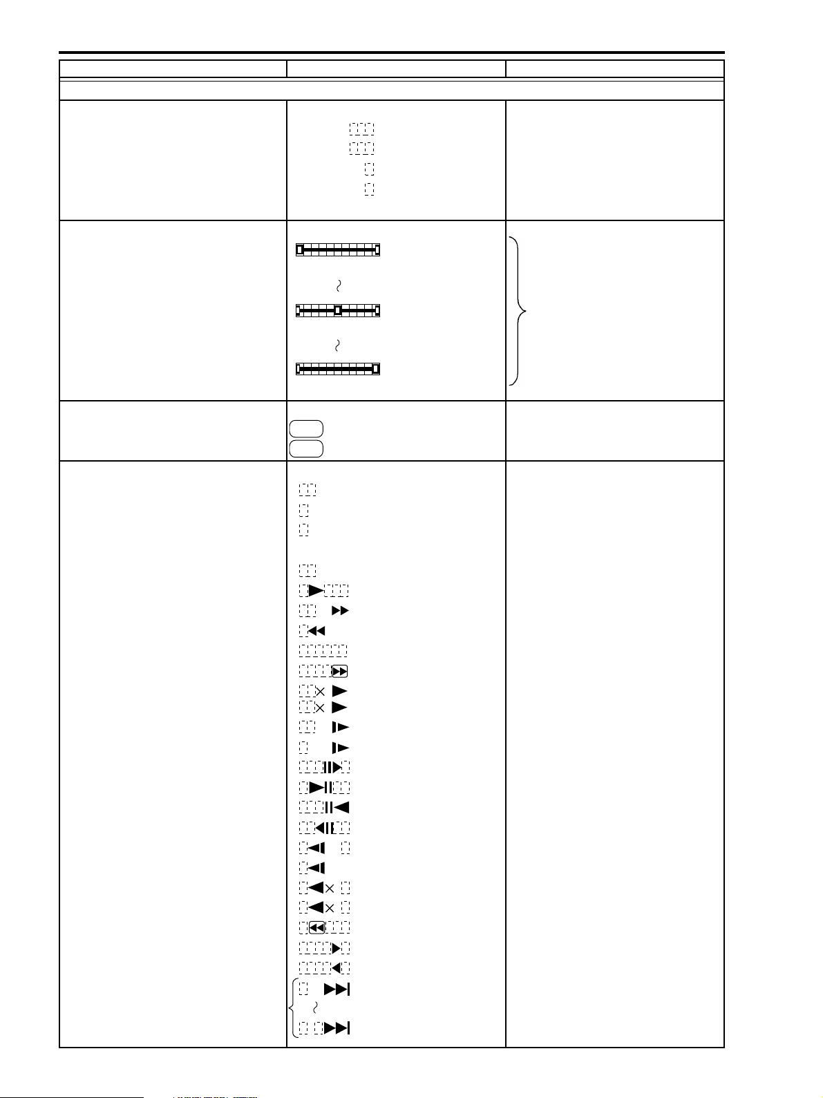
ZR10A
CHAPTER 1. GENERAL DESCRIPTION OF PRODUCT
Menu indication NTSC Model Remarks
2 : VCR Mode
Audio output indication
12 bit, stereo 1 selected
12 bit, stereo 2 selected
12 bit, 1:1 mix selected
12 bit, mix/variable selected
16 bit No indication
Audio mix ratio indication
At ST-1 : ST-2 =1 : 0
At ST-1 : ST-2 =1 : 1 seconds after having selected the mix
At ST-1 : ST-2 =0 : 1
Tape speed indication
SP mode
LP mode LP
Operation mode indication
Recording Indication in green
Pause Indication in green
With the cassette removed Indication in green ; blinks in red when
STEREO1
STEREO2
MIX
/
FIXED
MIX
/
VARI.
ST1 ST2
ST1 ST2
ST1 ST2
SP
REC
PAUSE
EJECT
The indication is shown for about 4
variables or mix ratio.
an error occurs
Stop Indication in green
Playback Indication in green
FF Indication in green
REV Indication in green
No tape
FF playback Indication in green
Double speed playback Indication in green
Normal speed playback Indication in green
Forward slow playback Indication in green
(Forward slow playback)
Frame-by-Frame playback Indication in green
Still picture playback Indication in green
Reverse still picture playback Indication in green
Reserve frame-by frame playback Indication in green
Reverse slow playback Indication in green
Reverse slow playback Indication in green
Reverse playback at normal speed Indication in green
Reverse playback at double speed Indication in green
REV playback Indication in green
Edit search Indication in green
Reverse edit search Indication in green
Date/photo search (forward direction)
STOP
FF
/
/
10
10
1
REW
2
1
5
/
5
/
10
1
2
1-18
Page 17
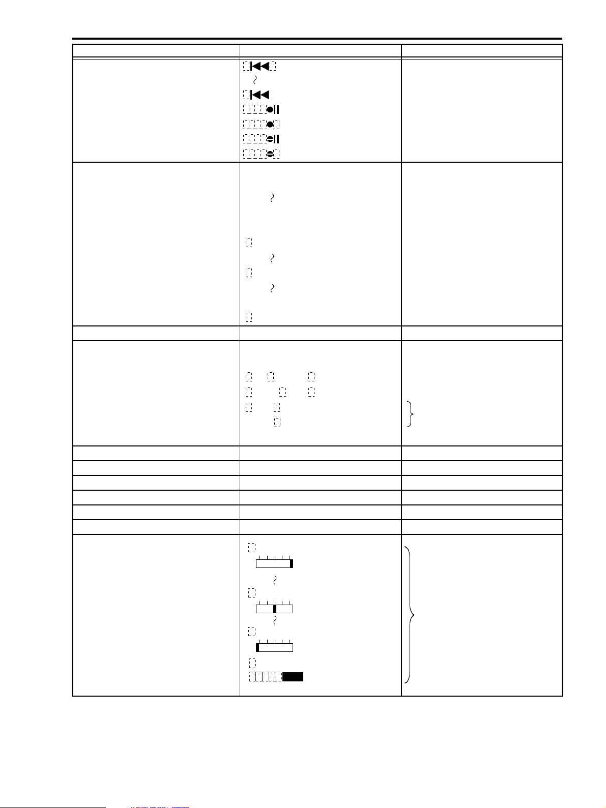
Menu indication NTSC Model Remarks
Reverse date/photo search
AV insert feature, paused recording
AV insert, recording
Audio dubbing, recording pause
Audio dubbing, recording
Tape counter
Time code display 0 : 00 : 00 : 00
Undetermined – : –– : –– : ––
Zero set memory
Undetermined – : –– : ––M
Tape remaining time indication Same as in the camera mode
Audio dubbing/insert or search operation
indications
AV insert mode selection
Audio dubbing selection
Date searching
Still picture photo searching
Other modes except searching No indication
Battery status Same as in the camera mode
Button lithium battery low warning indication
Remote controller code indication Same as in the camera mode
Digital features indication Same as in the camera mode
Battery warning indication Same as in the camera mode
Dew condensation warning Same as in the camera mode
Volume indications
1
10
7 : 59 : 59 : 29
7 : 59 : 59M
0 : 00 : 00M
-7 : 59
PHOTO
Same as in the camera mode
: 59M
A/V INSERT
AUDIO
DATE
DUB.
SEARCH Displayed for approx. 4 seconds after
SEARCH
VOLUME
+–
ZR10A
CHAPTER 1. GENERAL DESCRIPTION OF PRODUCT
selecting searching.
VOLUME
VOLUME
VOLUME
OFF
+–
Displayed for approx. 4 sec. when
switching between headphones and
speaker, and after adjustment.
+–
1-19
Page 18
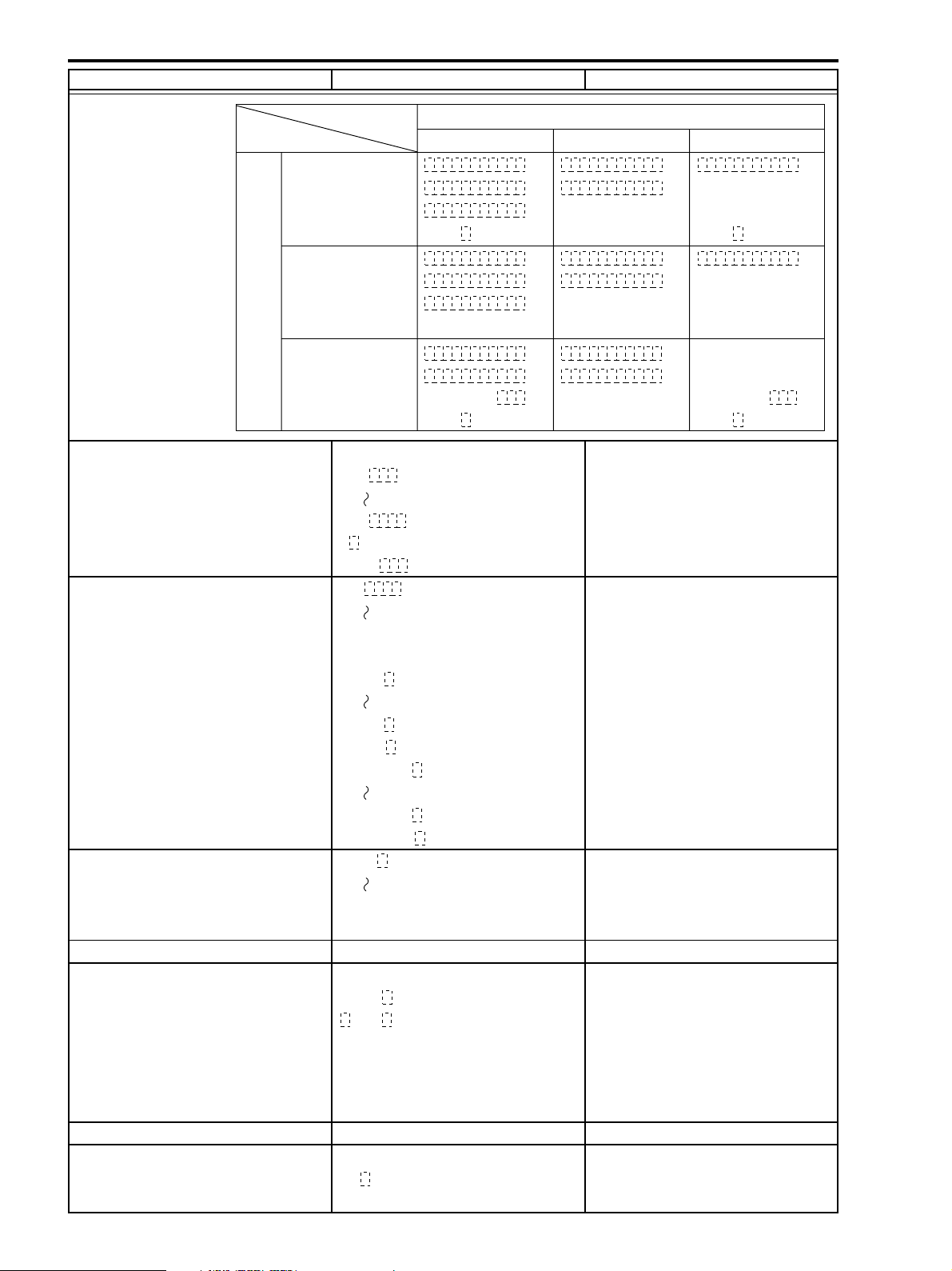
ZR10A
CHAPTER 1. GENERAL DESCRIPTION OF PRODUCT
Menu indication NTSC Model Remarks
Data code indications
Date setting
Time setting
Date&time selection
Date&time setting
Camera data
Aperture indication F1.0
F99
Lens opening fully closed F CLOSE
Undetermined F
Shutter speed indication 1/4
– – –
Data code settings
Date&time Camera Data
F1. 8
JAN.1, 2000
12 : 34 : 56 AM
12 : 34 AM
JAN.1, 2000
1/
1000 JAN.1, 2000
F1. 8
1/
1000
F1. 8
1/
1000 JAN.1, 2000
This unit’s aperture range is from F1.8.
No full closing of the lens opening in this unit.
This unit’s shutter speed is 1/15 sec.,
1/60 to 1/8000 sec.
Date&time and Camera Data
F1. 8
1/
1000
F1. 8
1/
1000
12 : 34 : 56 AM
F1. 8
1/
1000
12 : 34 AM
1/15000
1/- - - - -
Time (hours/minutes) selection 12 : 00
11 : 59
Undetermined
Time (hours/minutes/seconds) 12 : 00 : 00 AM
Undetermined
Date (year/month/day) JAN. 1, 1990 Auto date function: 2000 to 2020
Undetermined
Wind screen indication Same as in the camera mode
Audio information indications
Audio dubbing/audio input terminal selected
Audio dubbing/microphone input
terminal selected
16bit 16bit
12bit 12bit
Undetermined No indication
16:9 mode indication Same as in the camera mode
DV input
DV input DV IN
Other No indication
– – : – – – –
11 : 59 : 59 PM
– – : – – : – – – –
DEC. 31, 2089
– – –
AUDIO
AM
PM
. – –, – – – –
IN
MIC. IN
1-20
Page 19

CHAPTER 1. GENERAL DESCRIPTION OF PRODUCT
5-3 Warning Indications
COPYRIGHT PROTECTED PLAYBACK IS RESTRICTED
• When playing back a tape copying of which is prohibited.
COPYRIGHT PROTECTED DUBBING IS RESTRICTED
• Copying prohibited information detected at the DV input.
SET THE TIME ZONE, DATE AND TIME
• The unit has been switched on, but time zone, date, and time are not set.
REMOVE THE CASSETTE
• A cassette was inserted while there was a mechanism error or dew condensation.
CHECK THE DV INPUT
• When the REC button is pressed in the mode in which it is possible to switch the camcorder to recording, however there is
no connection with the DV, or the connected unit is not being recognized.
ZR10A
CHANGE THE BATTERY PACK
• The battery pack power is low.
CONDENSATION HAS BEEN DETECTED
• It appears when moisture condensation occurs. if a tape is inside, “Remove the cassette” appears next.
THE TAPE IS SET FOR ERASURE PREVENTION
• When the REC button is pressed in the mode in which it is possible to switch the camcorder to recording, however the
cassette is protected with its erasure prevention tap. When having switched the camcorder on in the camera mode, pressed
the START/STOP button, or inserted a cassette.
TAPE END
• The end of the tape has been detected, or when a key used to forward the tape (FF, PLAY, etc.) is pressed while detection is
activated in the mode in which it is possible to switch the unit to tape forwarding.
CHECK THE CASSETTE [LP MODE]
• When the Audio Dubbing button or AV insert button is pressed while in the tape portion recorded in the LP mode. Or when
the LP mode is detected while the audio dubbing or AV insert feature was activated.
CHECK THE CASSETTE [AUDIO MODE]
• When the Audio Dubbing button is pressed while in the tape portion recorded in the 16 bit or 4 ch sync recording mode. Or
when the 16 bit or 4 ch sync recording mode is detected while the audio dubbing feature was activated.
CHECK THE CASSETTE [BLANK]
• A blank portion has been detected while the audio dubbing feature or AV insert feature is activated.
1-21
Page 20
ZR10A
CHAPTER 1. GENERAL DESCRIPTION OF PRODUCT
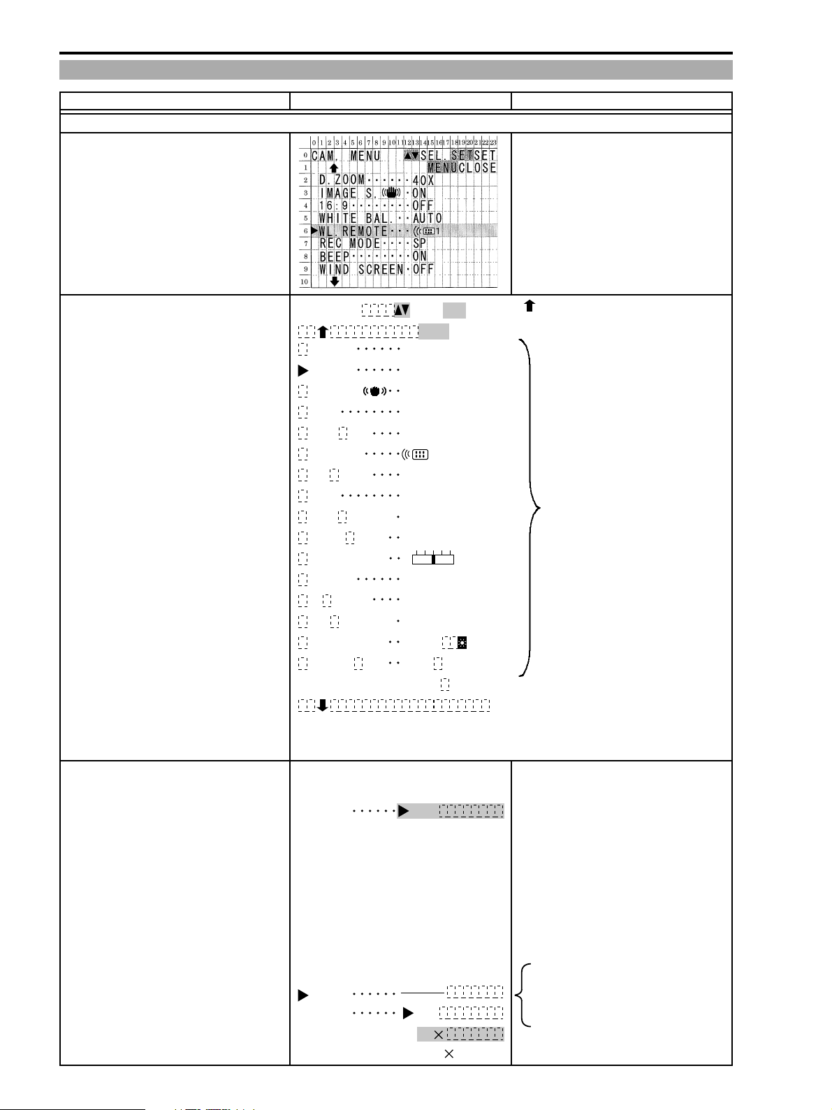
5-4 Menu Indications
Menu indication NTSC Model Remarks
1 : Camera mode
Menu Title
Key operation guidance indications items are available above.
Menu items
CAM. MENU
SHUTTER
D. ZOOM
IMAGE S.
16 9
:
WHITE BAL
WL. REMOTE
REC MODE
BEEP
WIND SCREEN
AUDIO MODE
BRIGHTNESS
MIRROR
TV SCREEN
D/T DISPLAY
T. ZONE/DST
D/TIME SET
SEL.
AUTO
40X
ON
OFF
AUTO
SP
ON
ON
12bit
ON
ON
ON
N.Y.
JAN.
12 00:
SETSET
CLOSE
MENU
1
1,
AM
+–
2000
is displayed if there are any menu
Upward/downward direction 3-scroll
The cursor selection item row is indicated in a sky blue. Item rows whose setting is
restricted are indicated in purple. Data is indicated as “_____”.
Menu contents indicated in purple in the modes that
cannot be executed (photo).
Shutter speed
Setting impossible
Digital zoom
SHUTTER
SHUTTER
D. ZOOM
AUTO
1/60
1/100
1/250
1/500
1/1000
1/2000
1/4000
1/8000
OFF
40
200
1-22
In modes other than the auto mode
when the EXP lock cannot be set, the
back ground becomes purple. The
data is indicates as _____.
Page 21
ZR10A
CHAPTER 1. GENERAL DESCRIPTION OF PRODUCT
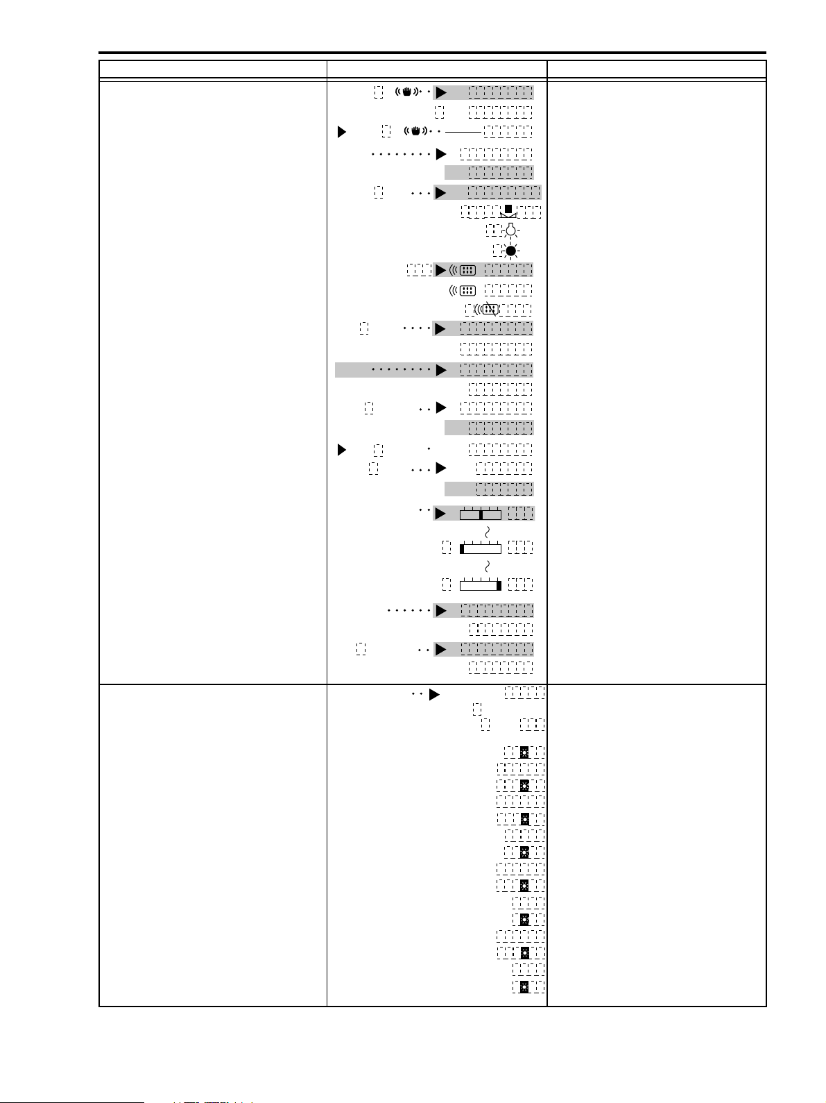
Menu indication NTSC Model Remarks
Image stabilizer
Green mode
16:9 mode
White balance
Remote controller code
Recording mode
Sound system
Wind screen
With the external microphone connected. By forced turning off the data section
Audio mode
LCD brightness adjustment
IMAGE S.
IMAGE S.
16 9:
WHITE BAL.
WL. REMOTE
REC MODE
BEEP
WIND SCREEN
WIND SCREEN
AUDIO MODE
BRIGHTNESS
ON
OFF
ON
OFF
AUTO
SET
INDOOR
OUTDOOR
1
2
OFF
SP
LP
ON
OFF
ON
OFF
– – –
16bit
12bit
The background becomes purple when
ON is forces in the Green mode.
The data is indicated as ___.
is displayed as ___ in purple.
+–
Self-shooting
Date&time indication
Shooting zone/summertime T. ZONE/DST
MIRROR
D/T DISPLAY
ON
OFF
ON
OFF
LONDON
JAN.
12
LONDON
PARIS
PARIS
CAIRO
CAIRO
MOSCOW
MOSCOW
DOBAI
DOBAI
KARACHI
KARACHI
DACCA
DACCA
BANGKOK
BANGKOK
1.
:
00
+–
+–
2000
AM
1-23
Page 22
ZR10A
CHAPTER 1. GENERAL DESCRIPTION OF PRODUCT
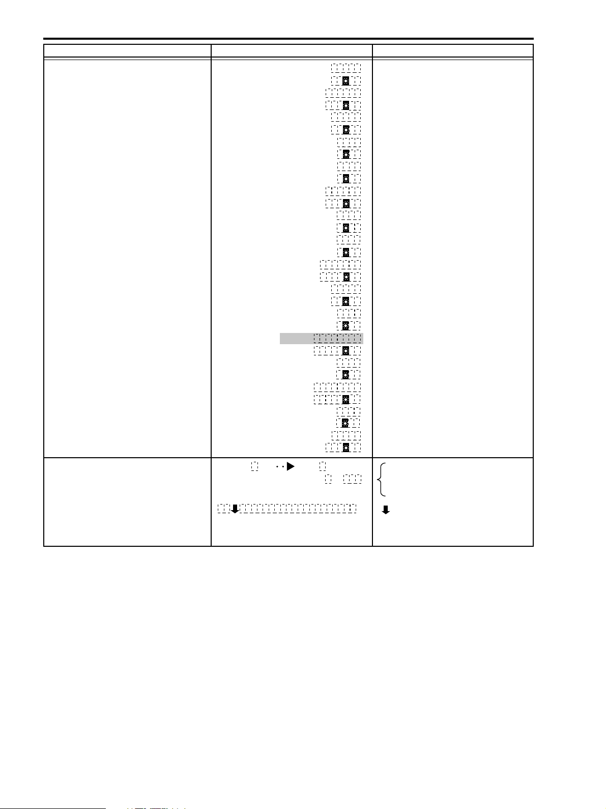
Menu indication NTSC Model Remarks
Date&time setting
Key operation guidance indications
H. KONG
H. KONG
TOKYO
TOKYO
SYDNEY
SYDNEY
SOLOMON
SOLOMON
WELLGTN
WELLGTN
SAMOA
SAMOA
HONOLU.
HONOLU.
ANCHOR
ANCHOR
L. A.
L. A.
DENVER
DENVER
CHICAGO
CHICAGO
N. Y.
N. Y.
CARACAS
CARACAS
RIO
RIO
FERNAN.
FERNAN.
AZORES
AZORES
JAN.D/TIME SET 1, 2000
:
12 00
AM
If selecting when no area is set, the
area/summer time items and date
setting items start to blink.
is displayed if there are any menu
items are available below.
* Date&time are blinking in sky blue during setting.
1-24
Page 23
CHAPTER 1. GENERAL DESCRIPTION OF PRODUCT
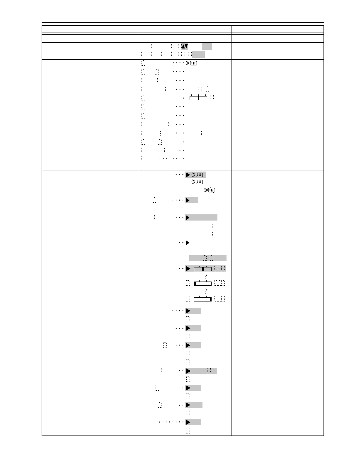
Menu indication NTSC Model Remarks
2 : VCR Mode
Menu titles Green indication
Key operating guide MENU, CLOSE are purple.
Menu items
Remote controller sensor
Recording mode
Data code
Date&time selection
LCD brightness adjustment
VTR
MENU
WL. REMOTE
REC MODE
DATA CODE
D/TIME SEL
BRIGHTNESS
DISPLAYS ON
6SEC. DATE OFF
OUTPUT CH L/R
AUDIO DUB.
WIND SCREEN
AUDIO MODE
BEEP
* The selection item is indicated in a sky blue.
WL. REMOTE
REC MODE SP
DATA CODE
D/TIME SEL.
BRIGHTNESS
SEL
SETSET
CLOSE
MENU
1
SP
DATA/TIME
DATA & TIME
+–
AUDIO IN
OFF
12bit
ON
1
2
OFF
LP
DATE/TIME
CAMERA DATA
CAM. & D/T
DATE
TIME
DATE &
TIME
+–
ZR10A
Character display during playback
Date auto indication
Bilingual
Audio dubbing
Wind screen
Audio mode
Warning buzzer
DISPLAYS
6SEC. DATE
OUTPUT CH
AUDIO DUB.
WIND SCREEN
AUDIO MODE
BEEP
+–
+–
ON
OFF
OFF
ON
L/R
L/L
R/R
AUDIO IN
MIC. IN
ON
OFF
12bit
16bit
ON
OFF
1-25
Page 24
ZR10A
CHAPTER 1. GENERAL DESCRIPTION OF PRODUCT
6. Data Backup
6-1 Main power supply backup
There is no item backed up only with the main power supply.
6-2 Backup with the main power supply or the backup power supply (button type lithium battery)
Items backed up with the main power supply or the backup power supply (button type lithium battery).
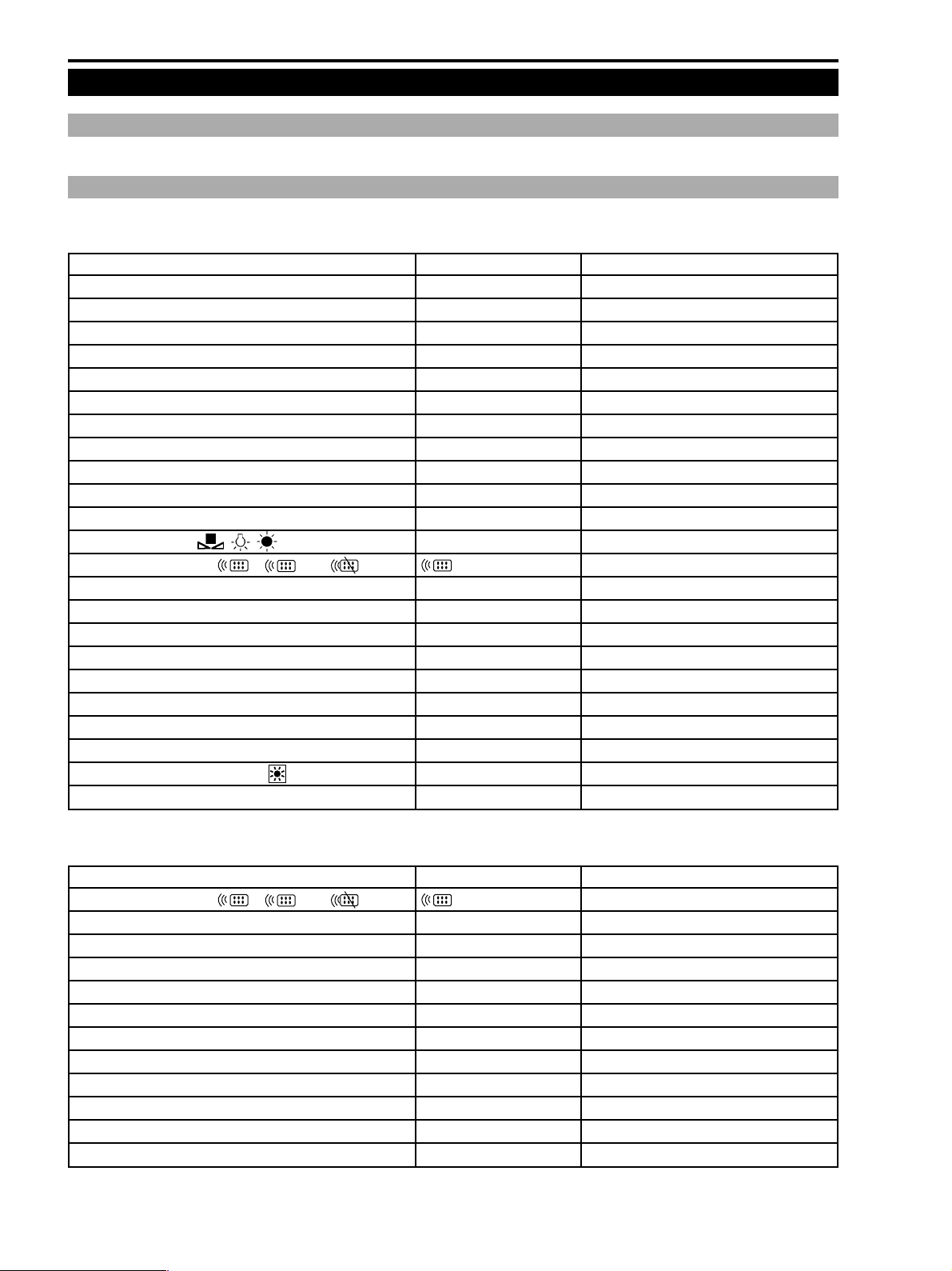
Camera Mode
Item Default Reference
DE, DF menu cursor position Digital off
DF types Auto fading
DE types Art
White balance data (when set) —
Lens position (focus, zoom) — No relation with the AF/MF
Lens cam locus — No relation with the AF/MF
Digital zoom position Optical TELE end
Shutter speed (sec.)<auto, 1/60 (50) to 1/8000> Auto
Digital zoom<off, 40×, 200×>40×
Stabilizer<on, off> On
16 : 9<on, off> Off
White balance<auto, , , > Auto
Remote controller code<
Recording mode<SP, LP> SP
Warning buzzer<on, off> On
Wind screen<on, off> Off
Audio mode<16 bit, 12 bit> 12 bit
LCD brightness adjustment<-7 to ±0 to +7>(scale indication)
On screen<on, off> On
Self shooting<mirror, normal> Mirror
Date&time indication<on, off> Off
Zone/Summertime<for 24 cities+ > Tokyo/N.Y./PARIS
Date&time setting — : — : —
,
1
,
2
off
>
1
±0 (center)
Backup with the button type lithium battery
Backup with the button type lithium battery
Backup with the button type lithium battery
Backup with the button type lithium battery
Backup with the button type lithium battery
Backup with the button type lithium battery
Backup with the button type lithium battery
Backup with the button type lithium battery
Backup with the button type lithium battery
Backup with the button type lithium battery
Backup with the button type lithium battery
Backup with the button type lithium battery
Backup with the button type lithium battery
Backup with the button type lithium battery
Backup with the button type lithium battery
Backup with the button type lithium battery
VCR mode
Item Default Reference
Remote controller code<
Recording mode<SP, LP> SP
Data code<date&time/camera data/date&time and camera data>
Date&time selection<date/time/date&time> Date&time
LCD brightness adjustment<-7 to ±0 to +7>(scale indication)
Character indication during playback On
Date&time auto indication<on, off> Off
Bilingual<main+sub/main/sub> Main+sub Reset (Turn the power off to reset)
Audio dubbing input<audio input/microphone input> Audio input
Wind screen<on, off> Off
Line IN; audio mode<16 bit/12 bit> 12 bit
Warning buzzer<on, off> On
,
1
,
2
off
>
1
Date&time
±0 (center)
Backup with the button type lithium battery
Backup with the button type lithium battery
Backup with the button type lithium battery
Backup with the button type lithium battery
Backup with the button type lithium battery
Backup with the button type lithium battery
Backup with the button type lithium battery
Backup with the button type lithium battery
Backup with the button type lithium battery
Backup with the button type lithium battery
Backup with the button type lithium battery
1-26
Page 25
ZR10A
CHAPTER 1. GENERAL DESCRIPTION OF PRODUCT
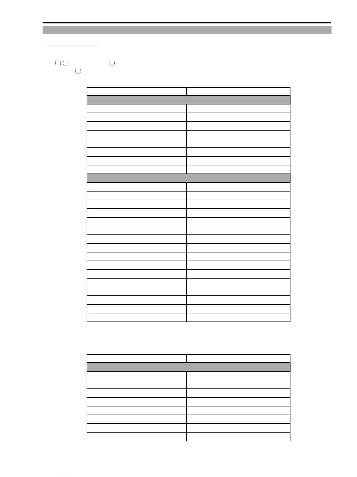
6-3 Backup conditions by switch operation
6-3-1 Turn off power
The backup condition of each item when the power switch is set to “OFF” or “VCR”, and then set again to the Camera position while
/P switch was in the P (Program AE) mode.
the
When in the
(Camera) again.
(full auto) mode, it becomes same as the “Switching to the full auto mode” of 9-4-2 after having turned power ON
Item
● Camera functions
Types of Program AE modes Backup
Auto focus on/off Backup
Exposure lock on/off Reset (becomes “Off”)
DE, DF on/off Reset (becomes “Off”)
Headphones volume Backup
Self timer on/off Reset (becomes “Off”)
On-screen on/off Backup
Counter zero setting memory Backup
● Camera menu item setting
Shutter speed setting Backup
Digital zoom setting Backup
Stabilizer on/off Backup
16 : 9 on/off Backup
White balance setting Backup
Remote controller code setting Backup
Recording mode setting Backup
Warning buzzer on/off Backup
Wind screen on/off Backup
Audio mode setting Backup
LCD brightness adjustment Backup
Self shooting setting Backup
On-screen on/off Backup
Date&time indication setting Backup
Zone/summertime setting Backup
Date/time setting Backup
Condition after having switched power ON again
* When the unit power goes off with the 5-minute off timer and the LANC power off feature while in the paused recording mode, the
backup is exactly same as for the “Power OFF”.
Item
● VCR functions
Headphones volume Backup
Speaker volume Backup
On-screen on/off Reset (becomes “Off”)
Counter zero setting memory Backup
Data code indication on/off Reset (becomes “Off”)
Audio 12 bit output selection Reset (becomes “Stereo 1”)
Mixed balance setting Backup
Photo search/date search of search selection Reset (becomes “Photo Search”)
Condition after having switched power ON again
1-27
Page 26
ZR10A
CHAPTER 1. GENERAL DESCRIPTION OF PRODUCT
● VCR menu timer setting
Remote controller code setting Backup
Recording mode setting Backup
Data code setting backup
Date&time selection setting Backup
LCD brightness adjustment Backup
Character display in the playback mode on/off
Date auto information on/off Backup
Bilingual setting Reset (becomes “Main+Sub”)
Audio dubbing input setting Backup
Wind screen on/off Backup
Line IN audio mode setting Backup
Warning buzzer on/off Backup
Backup
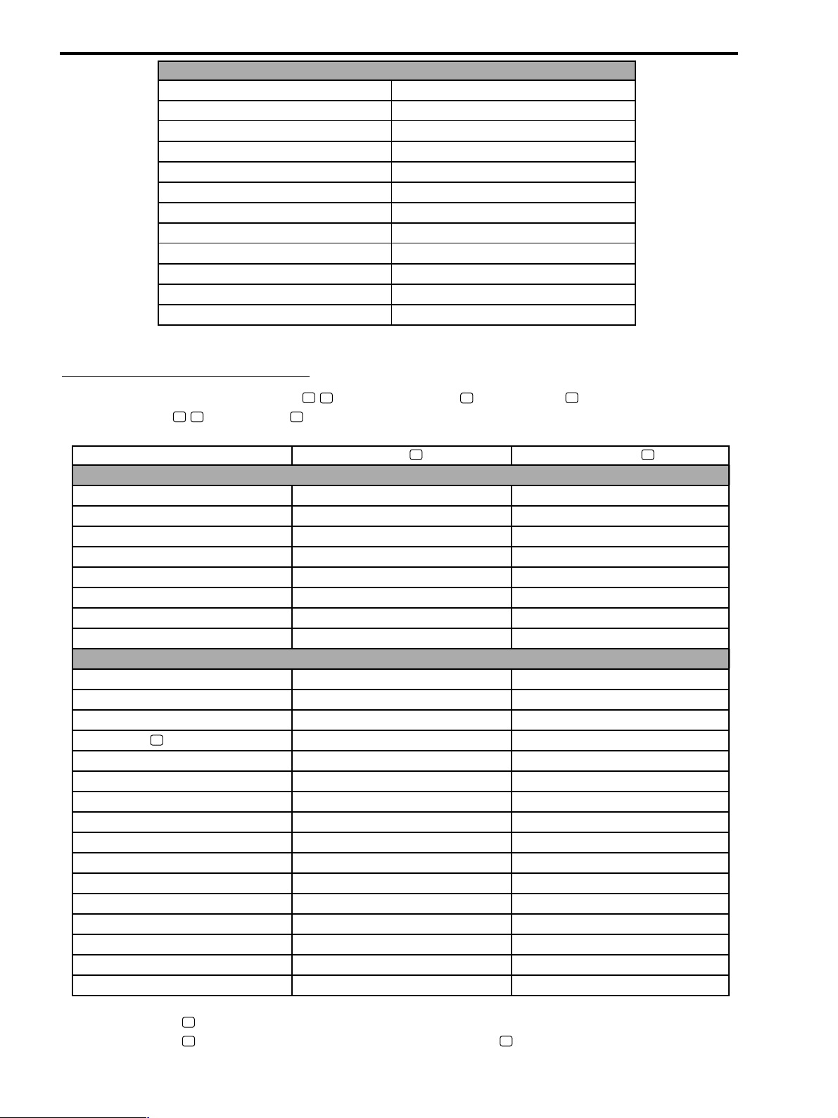
6-3-2 Switching the Program AE mode
The backup condition of each item when the /P switch is switched from P (Program AE) to (full auto), or to other program
AE mode while the
/P [switch is set to P ].
Item Switching to the (full auto) Switching to another P (Program)
● Camera functions
Program AE mode types *1 ———
Auto focus on/off Reset (becomes “On”) Backup
Exposure lock on/auto Reset (becomes “Off”) Reset (becomes “Off”)
DE, DF on/off Reset (becomes “Off”) Backup
Headphones volume Backup Backup
Self timer on/off Backup Backup
On-screen on/off Backup Backup
Counter zero setting memory Backup Backup
● Camera menu item setting
Shutter speed Reset (becomes “Auto”) Reset (becomes “Auto”)
Digital zoom off/40×/200× Backup Backup
Stabilizer Reset (becomes “On”) Backup
16 : 9 (with the (full auto) becomes “Off”)
White balance × (becomes “Auto”) Backup
Remote controller code setting Backup Backup
Recording mode setting (SP/LP) Backup Backup
Warning buzzer on/off Backup Backup
Wind screen on/off Backup Backup
Audio mode setting Backup Backup
LCD brightness adjustment Backup Backup
Self shooting setting Backup Backup
On-screen on/off Backup Backup
Date&time indication on/off Backup Backup
Zone/summertime setting Backup Backup
Date/time setting Backup Backup
Becomes “Off” *2 Backup
*1 : When set again to “P”, turns to auto.
*2 : When set again to “
”, turns back to the previous condition before switching to “ ” (full auto).
P
1-28
Page 27
CHAPTER 1. GENERAL DESCRIPTION OF PRODUCT
7. Other
7-1 Green Mode
Default status in the Green mode
• Focus ................................. Auto
• Exposure ........................... Auto
• White balance ................... Auto
• DE, DF .............................. Off
• Stabilizer ........................... On
• Shutter ............................... Auto
• 16 : 9 ................................. Off
Items other that the above remain in their original settings even in the Green mode.
Keys which do not function in the Green mode :
• Focus button
• Exposure button
• D.E.SEL
• D.E.EXE
ZR10A
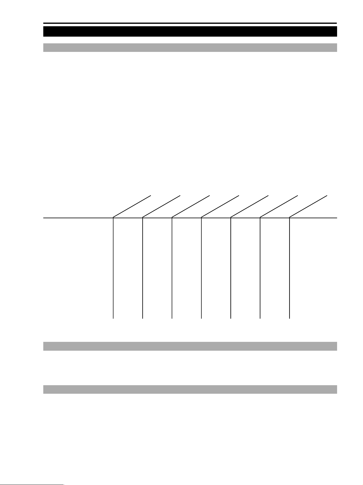
The relation between the Program AE modes and the shooting functions
Item
Auto focus ON/OFF Forced ON KKKKKK
Shutter speed setting × K ЧЧЧЧЧ
AE lock × KKKKKK
AE exposure compensation × KKKKKK
Stabilizer ON/OFF Forced ON KKKKKForced OFF
White balance setting Forced auto KKKKKK
Wind screen ON/OFF KKKKKKK
Digital zoom KKKKKKK
16:9 × KKKKKK
Digital fader × KKKKKK
Digital features × KKKKKK
Photo shooting KKKKKKK
Green
Auto
Sports
Portrait
Spotlight
Sand&Snow
Low light
7-2 On-screen
• Switching the on-screen mode on/off can be done with LANC, the remote controller on the menu.
• In the on-screen mode, characters above the line are white (characters inside the LCD panel, CVF are displayed in color).
• In the default, indications in the camera mode are on, while in the VCR mode are off.
7-3 Headphones, speaker
• In the camera mode the speaker is off.
• The speaker is on during normal playback in the VCR mode. Volume is adjusted with the multidial.
• Volume of the headphones can be adjusted only when the headphones are connected, with the multidial.
• The speaker is off when the headphones are connected.
1-29
Page 28
ZR10A
CHAPTER 1. GENERAL DESCRIPTION OF PRODUCT
7-4 Battery status (Remaining battery, Warning indications, shut off by insufficient power)
Battery status
• When using the unit on a battery, the battery status is indicated in five steps, i.e. 100%, 75%, 50%, 25% and 0% (approximate
values) until the insufficient-power warning appears, then is reset by switching the power off. When the unit is off and on again,
the battery regains its power (the battery status indication shows higher) sometimes. However, once the battery low warning
appears, the Low battery warning is displayed even when the power is regained by turning the unit off and on.
• The battery status indication is off when using the unit on the AC power adapter. However, when the power level decreases,
because of some malfunction (dropping below the battery low level), the battery low warning will go on. Then, should the power
increase above the battery low level, the battery low warning will disappear.
Battery low warning appears when the voltage across the battery connectors falls below approx. 6.3V (when using with this product)
•
7-5 System data indication
Camera Mode VCR Mode
Camera Picture Rec Search DIF Input Blue Back
Data Code (Date&Time)
Data Code (camera data) ××× F— — —etc. ×F— — —etc. K
Time Code KKK Main unit KK
Audio Mode (12/16bit)
WIDE/Normal
CGMS (warning) × KK DIF side × K
SP/LP
× (Appears in LANC) × (Appears in LANC)
K 4 sec. indication
K Setting indication
K Setting indication
× K DIF side × K
× K DIF side × K
K
×— — — ×— — — K
K Setting indication K Setting indication
PB (incl. special playback)
K
* IF there is no tape, the Time Code is shown as “—:—:—:—” in the unrecorded portion.
* CGMS : When copying is prohibited, the LINE OUT, CVF (panel) do not appear.
7-6 Data code indication
It is possible to independently set the Data Code indications on/off (regardless the other on-screen character indications).
7-7 MP tape
MP tape cannot be recorded in the LP mode. Even with the LP mode selected in the Menu, the tape will be set to the SP mode forcibly.
Playback of LP-recorded tape is made in LP mode.
7-8 Warning buzzer
Warning buzzer is activated in the following cases :
Mode Sound
Turning the power on pip
Insertion of a cassette with the erasure prevention tap set to SAVE (camera mode)
EJECT cover fully open (also in when power is off) pippip
Recording start (camera mode) pip
Recording pause activation (camera mode) pippip
Halfway pressed photo button ; OK status pippip
Mode transition (VCR mode) pip
Photo recording start pip
Dew condensation, mechanism error, and 5 seconds before going off with beep (a simple tone) ×5 times
the 5-minute timer in the recording pause (*) mode
Setting button operation of an item which cannot be selected in the menu buuh
20, 15, 10 seconds before going off with the 5-minute timer in the recording pause (*) mode
Self timer (simultaneous tally flashing) pippip ×8 times (every second)
pip-pip-pip
beep-beep-beep
pip ×8 times (every 0.25 second)
Including recording pause (*) in the audio dubbing, AV insert modes.
*Frequency of the “pip” tone is 4 kHz, of the “beep” tone is 2 kHz, of the “buuh” tone is 1 kHz.
1-30
Page 29
ZR10A
CHAPTER 1. GENERAL DESCRIPTION OF PRODUCT
7-9 Analog line recording, DV recording description
1 Set the power switch to “VCR”.
Power LED (green) lights up, with a cassette inserted in the stop mode. A signal at the terminals
(DV, S-VIDEO, AV mini terminal), the headphones terminal, and the speaker terminal (headphones priority) is on.
2 Connect a cable which is connected to a recording source to the S-VIDEO terminal (video signal) and AV mini terminal (audio
signal), or to the AV mini terminal (video&audio signal), or to the DV terminal, then turn the recording source on.
If several recording sources are connected to the above terminals, the unit selects a recording source in the following priority order.
Priority order : DV terminal > S-VIDEO terminal > AV mini terminal
Note : Should a playback picture be on (including special playback), the playback picture has priority.
3 Press REC STANDBY on the remote controller.
The unit enters the recording pause mode. At this stage the analog line input turns to S-VIDEO, AV mini terminal.
4 Press PLAY/PAUSE on the remote controller.
The unit starts to record video and audio signal incoming through a terminal selected in 2.
(PLAY/PAUSE toggles recording and recording pause.)
5 Press STOP. Recording stops.
* In the DV recording mode, recording stops automatically if the DV input signal goes off.
* In the analog line recording mode, analog recording continues even when signal comes through the DV terminal, but pausing of the
analog recording mode will result in switching to the DV input terminal.
* Input signal CGMS (Copy Generation Management System : Copying restriction)
Only copying of unrestricted signal can be recorded (CGMS=00).
While in the recording mode or paused recording mode, should the unit detect copy restriction signal (CGMS=11), or 1-time copy
permission signal (CGMS=10), recording will stop.
The LCD panel and CVF are in the blue back output. The speaker and headphones outputs are muted.
Regarding the CGMSD signal while in the DV recording mode, the unit detects CGMSD signal of both the audio and video, and
uses data of the stronger copy restriction signal.
The input/output signal status for each mode is as follows :
With the DV input signal on With the DV input signal off
LCD LCD, CVF DV terminal S, AV terminal LCD, CVF DV terminal S, AV terminal
Playback (incl. special playback)
No tape, STOP, FF, REW
REC PAUSE, REC
Analog signal input/copy right protection signal
1 Detection of the copy right signal added to the input signal.
Detection of the copy right signal : false sync pulse and CGMS-A (Copy Generation Management System for analog)
Signal detection time : max. 20 seconds.
Playback screen
DV input screen
DV input screen
OUT OUT
IN OUT Blue back OUT OUT
IN OUT
Playback screen
Line input screen*
* No signal if there is no line input.
OUT OUT
IN IN
1-31
Page 30

ZR10A
CHAPTER 1. GENERAL DESCRIPTION OF PRODUCT
Video ID1 detection/output
1 S1 signal output (NTSC, PAL models)
When the full mode video signal compressed (squeezed) from 16 : 9 screen to 4 : 3, is the S terminal outputs the identification signal
for automatic return to the 16 : 9 wide S1 screen (when playing back a tape with system data related to the camera 16 : 9 mode,
aspect ratio, etc. recorded on it).
NTSC → 16 : 9 full mode + 4 : 3 letter box mode identification signal output
PAL → 16 : 9 full mode identification signal output
2 Video ID1 output (NTSC model only)
When the full mode video signal compressed (squeezed) from 16 : 9 screen to 4 : 3 is output from the Composite Video terminal/
S terminal, the wide monitor for video ID1 outputs the identification signal for automatic return to the 16 : 9 screen (when playing
back a tape with system data related to the camera 16 : 9 mode, aspect ratio, etc. recorded on it).
3 Detection of S1 signal/video ID1 during line input (NTSC model only)
Detection of video ID1/S1 signals added to the video signal inputted from the composite/S terminals, and recording of the system
data related to the aspect ratio.
Detection/output of closed captions
1 Closed caption signal output (NTSC model only)
When playing back a tape with closed caption information on it, the closed caption signal is added to the video signal for output.
The caption data in displayed on the monitor if the monitor has a closed caption decoder built in it.
2 Closed caption signal detection (NTSC model only)
During analog/digital input recording the inputted signal of closed caption information is detected and recorded.
7-10 Audio dubbing
1. Tapes for Audio dubbing
Audio dubbing is possible only on tapes recorded in the 12 bit/SP mode other than the 4 channel sync recording. With all other tapes
the unit stops. It stops when it detects LP mode, 16 bit mode, 4 channel sync type recording, or no recording (warning indication
appears).
2. Audio dubbing signal input source selection
With the VCR menu, select the audio dubbing input source. (In the PAL, iPAL models there is no menu and the source can be
microphone only.)
There are two types of items that can be selected ; Line (AV mini terminal), and MIC. With the MIC selected, if an external
microphone is connected, the input signal comes via the external microphone, if not connected, the input signal will come from the
built-in microphone. As to the line video output note the following :
1) When using the AV input mini terminal : S-VIDEO, AV mini terminal input mode. Speaker output monitoring available.
2) When using the external microphone input : S-VIDEO, AV mini terminal output mode. Speaker off, line monitoring available.
3) When using the built-in microphone : S-VIDEO, AV mini terminal output mode. Speaker off, line monitoring available.
3. Audio dubbing operation
1 In the VCR mode, playback-pause the tape at a point from where audio dubbing is to begin, then press the audio dubbing button on
the remote controller.
The unit enters the audio dubbing mode (audio dubbing pause), and the ( ) symbol (audio dubbing) is being indicated on the LCD
panel (CVF).
2 Press the Pause [ ] button turn on sound of the microphone etc.
Audio dubbing starts.
3 Press the Stop [■] button where you want to stop.
The audio dubbing mode is being canceled, the audio dubbing symbol disappears from the display, and the unit stops.
• By pressing the Pause [ ] button instead of the Stop [■] button, the audio dubbing mode is not canceled, but instead returns to step
1 (audio dubbing pause).
• Another way to cancel the audio dubbing mode is to press the audio dubbing button on while in the audio dubbing pause mode.
• In order to set in advance the audio dubbing mode to stop at a certain point of the tape, press the Zero Set Memory button on the
remote controller at the desired point, then after having performed operation in step 2 the unit will automatically stop when it
reaches the point, and the audio dubbing mode will be canceled.
1-32
Page 31

ZR10A
CHAPTER 1. GENERAL DESCRIPTION OF PRODUCT
* Audio input source signal coming from the DV terminal cannot be after-recorded. When the audio dubbing mode is set, no signal
is output from the DV terminal. The sound monitored is the input sound only. Playback sound cannot be monitored.
* CGMS
• While in the playback mode, the CGMSA signal which is added to the video signal cannot be detected when coming via the analog
input. Do not connect the yellow video terminal while in the audio dubbing mode.
• The unit does not switch to the audio dubbing mode on a copy-restricted portion of a copy-restricted tape.
The unit stop when it enters a copy-restricted portion following a copy-allowed portion.
7-11 AV insertion
In the AV insertion mode, the unit overrides the ITI (Insert and Track Information) areas with the audio, video, and sub codes.
1. Tapes for AV insertion
Only SP recording is possible on tapes to be used for inserting. With all other tapes the unit stops.
When LP mode or no-recording is detected, the unit stops (warning indication).
2. AV insertion signal input source selection
Selection in being performed in the following priority order :
DV terminal (ACK detection) > AV mini terminal detection > no connection
As to the line video output note the following :
1) When using the DV input terminal : S-VIDEO, AV mini terminal output mode. Speaker output monitoring available.
2) When using the AV mini terminal : S-VIDEO, AV mini terminal output mode. Speaker output monitoring available.
3) No connection : S -VIDEO, AV mini terminal output mode. Speaker output muted.
3. AV inserting operation
1 In the VCR mode, playback-pause the tape at a point from where AV inserting is to begin, then press the AV insert button on the
remote controller.
The unit enters the AV insertion mode (AV insertion pause), and the (●
LCD panel (CVF).
2 Press the Pause [ ] button to insert picture and sound.
AV insertion starts.
3 Press the Stop [■] button where you want to stop.
The AV insertion mode is canceled, the AV insertion indication disappears from the display, and the unit stops.
• By pressing the Pause [
1 (AV insertion pause).
• Another way to cancel the AV insertion mode is to press the AV insert button on the remote controller while in the AV insertion
pause mode.
• In order to set in advance the AV insertion mode to stop at a certain point of the tape, press the Zero Set Memory button on the
remote controller at the desired point, then after having performed operation in step 2 the unit will automatically stop when it
reaches the point, and the AV insertion mode will be canceled.
* CGMS
• AV insertion is only possible with copy-unrestricted material (CGMS=00) for both DV input and analog input.
• The unit will stop when it detects a signal other than CGMS=00.
(AV insertion) appears on the LCD panel (CVF).
] button instead of the Stop [■] button, the AV insertion mode is not canceled, but instead returns to step
) symbol (AV insertion paused) is being indicated on the
1-33
Page 32
ZR10A
CHAPTER 1. GENERAL DESCRIPTION OF PRODUCT
7-12 Multidial
Depending on the main unit mode, it is possible to carry out the VCR operation and various settings.
By turning the dial
Main Unit Mode Operation Function When turning the dial upwards
Menu (for both camera, VCR) Item selection dial The cursor moves up
When exposure in locked Exposure compensation The iris opens
In the manual focus mode Focus adjustment Focus moves toward the near side
In the VCR mode Sound volume adjustment Louder
By pushing the dial
Main Unit Mode Operation Function Dial Push
Recording paused Open/Close in the program AE menu Program AE mode selection
(selection confirmation)
Digital effects menu Switching between the digital effect modes Selection of a digital effect mode
Menu (for both camera, VCR) Menu setting switch Selection of an item
7-13 LCD panel/CVF (color viewfinder)
Power status of the LCD panel, CVF
1. Camera mode
LCD panel layout LCD panel power CVF power
When closed (facing the main unit)
When closed (facing outside) ON Forced cancellation of OFF
When open ON OFF
Self-shooting* ON ON
* : In the mirror mode the panel indications are forced on (CVF and on screen indications are displayed as usual), and only the
recording, recording pause, and eject indications are displayed. (During recording search and various menu settings, the mirror
mode is temporarily canceled.)
2. VCR mode
LCD panel layout LCD panel power CVF power
When closed (facing the main unit)
When closed (facing outside) ON OFF
When open ON OFF
Self-shooting ON OFF
OFF ON
the mirror mode.
OFF ON
1-34
 Loading...