

Page 1

imagePASS-G1/
Network Multi-PDL Printer Unit-G1
INSTALLATION PROCEDURE
PSプリントサーバユニット・G1
設置手順書
PUB No. F-IM-6545-000
ENGLISH
日本語
DEUTSCH
ITALIAN
PRINTED IN USA OR JAPAN
Page 2

2
1.1 Checking components
1.1.1 Checking the Contents
Follow the instructions herein when installing the image PASS-G1/Color Network Printer Unit-G1 to its host ma-
chine.
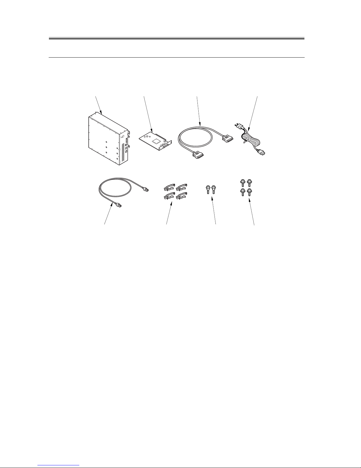
[1] Unit 1pc.
[2] Open I/F PCB 1pc.
[3] Communications cable 1pc.
[4] Power cable 1pc.
[5] Cross Ethernet cable 1pc.
[6] Cable clamp 4pc.
[7] Stepped screw 2pc.
[8] RS tightening screw(w/washer) 4pc.
[5] [6] [7]
[8]
[1] [2] [3] [4]
Page 3

3
1.2 Installation procedure
1.2.1 Before Starting the Work
Make sure the memory is added to 1024 MB in the iR
C6870/C5870.
RAM capacity can be checked with the procedure,
Service Mode > COPIER > Display > ACC-STS >
RAM.
Note: E604 will be displayed if the memory is not
added.
- Make the following selections in the host machine's
service mode, and set '3':COPIER>OPTION>
INT-FACE>IMG-CONT. (This way, the appropriate IP
address will automatically be setup for communica-
tion between the machine and its host machine.)
- Be sure that the back of the machine is at least 20cm
away from any wall as shown.
1.2.2 Installing to the
Host Machine
1. Turning Off the Main Power
Turning Off the Main Power
When turning off the main power, be sure to go
through the following in strict sequence to protect the
machine's hard disk:
[1] Hold down on the power switch on the control
panel for 3 sec or more.
[2] Operate on the touch panel according to the shut-
down sequence indicated so that the main power
switch may be turned off.
[3] Turn off the main power switch.
[4] Disconnect the power cable (for the power outlet).
2. Setup procedure
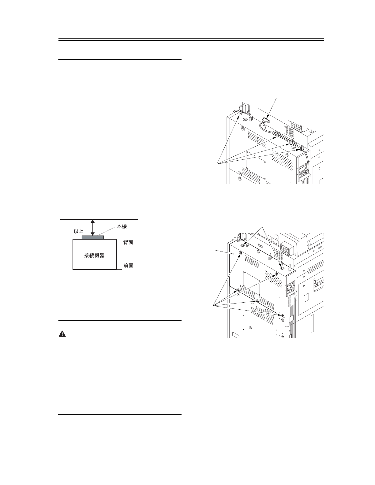
1) Removed the cable from clamping.
- Clamp[1] 4 places.
- Connector[2] 1 piece.
2) Remove the rear cover(upper) [1].
-7 screws [2].
3) Remove the controller box cover [1].
-16 screws [2].
20 cm min.
(rear)
Machine
(front)
Host machine
[1]
[2]
[2]
[2]
[1]
Page 4

4
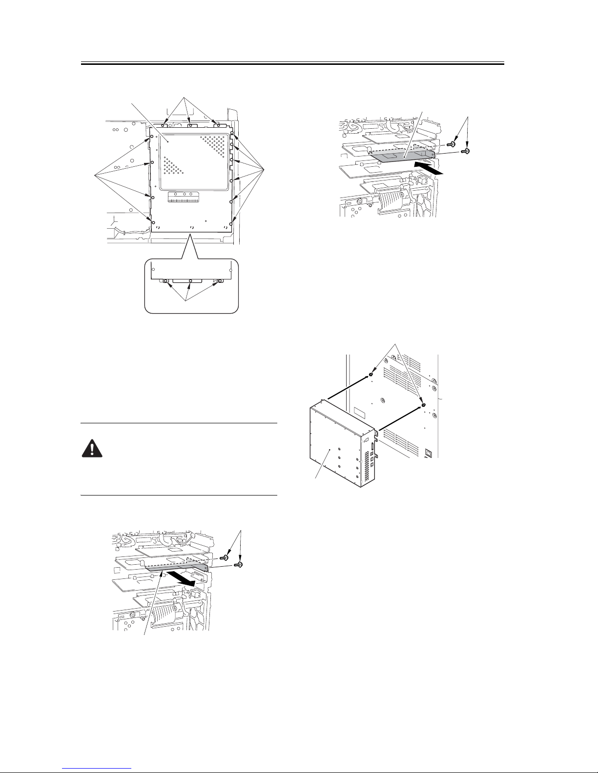
4) Prepare for the mounting of the open I/F PCB.
- Unscrew two screws [1] and remove the Main Con-
troller PCB (sub 0-A) [2].(Keep the removed screws
[1] for later.)
Ask the user to store the Main Controller PCB(sub 0-
A) in an appropriate location.
5) Using the screws you removed previously, mount
the included Open I/F PCB [2].
6) Mount the control box cover.
Before you removed at step 3.
7) Mount the rear cover(upper).
Before you removed at step 2.
8) Mount the cable.
Before you removed at step 1.
9) Fit the 2 included stepped screws [1] to the mount-
ing rear cover(lower), and hook the unit [2].
10) Using 4 RS tightening screws (w/washer) [1], at-
tach the Unit[2] to the rear cover(lower).
[1]
[2]
[2]
[2]
[2]
[1]
[2]
[1]
[2]
[1]
[2]
Page 5

5
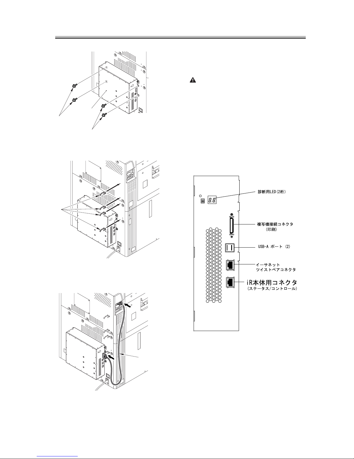
11) Mount a cable clamp [1] 4 pieces packaged with
the product.
12) Using the communications cable [1], connect the
open I/F PCB and the unit.
13) Using the cross Ethernet cable [1], connect the
unit and the host machine.
Note:
When the cross Ethernet cable [1] is connected, the
position of connected port is noted.
For the unit, there are two connected connectors for
Ethernet.
The connector for the cross Ethernet cable [1] is at a
position far from the USB port.
The connector that becomes it next to the USB port is
for the network.
Do not connect connector the cross Ethernet cable [1]
that becomes it next to the USB port.
[1]
[1]
[2]
[1]
[1]
Page 6

6
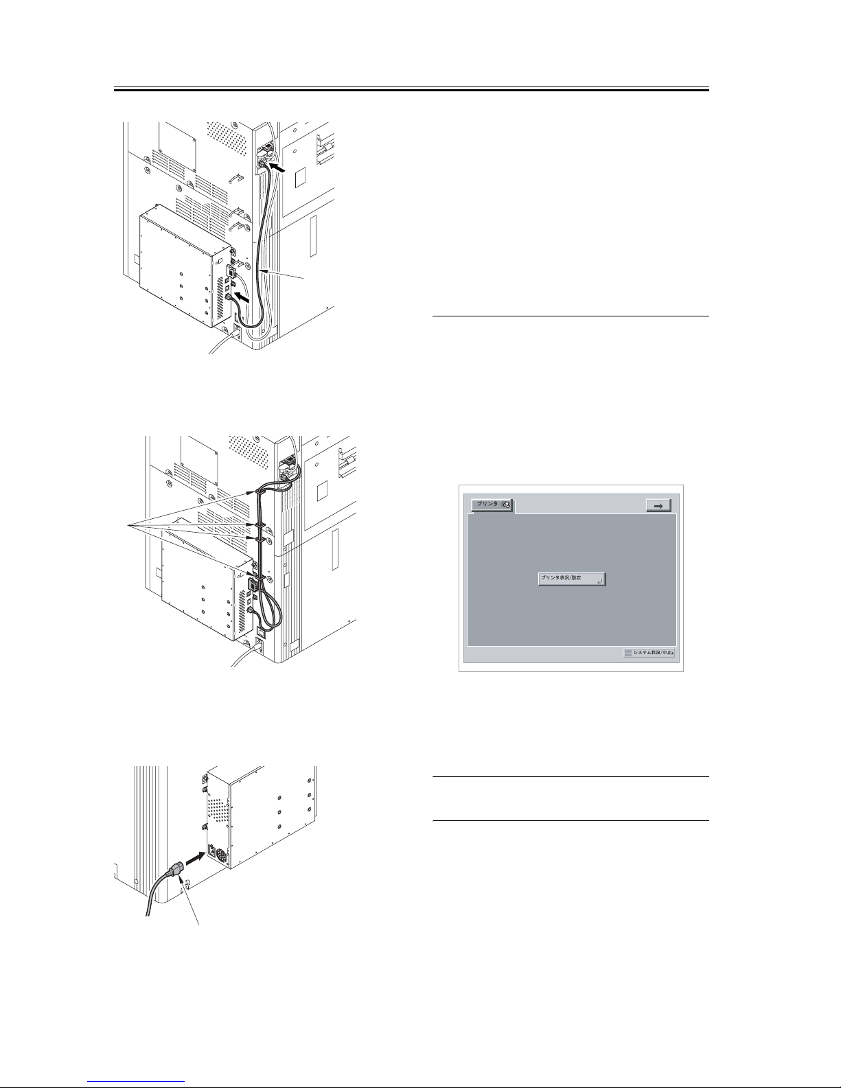
14) Using the cable clamp [1], bundle the cross Ether-
net cable and the communications cable together.
15) Connect one end of the power cable (for the power
outlet) [1] to the unit and the other end to the power
outlet.
16) Connect the host machine's power cable (for the
power outlet).
17) Turn on the host machine.
[Press the [Shutdown]key, After the machine has
been shutdown] is displayed on the LCD. Push the
button of [Shutdown].
[Turn off the main power switch(on the main unit's
right side)] is displayed on the LCD. Turn off the
power supply. Turn on the power supply in ten sec-
onds.
Host Machine
interface connector
Print Engine interface connector
DIAG 2-digit LEDs
10BaseT/100BaseTX/1000BaseT
connector for twisted pair Ethernet
USB-A ports (2)
(Print)
(Status/Control)
[1]
[1]
[1]
Page 7
7
1.2.3 Setting Up the Machine
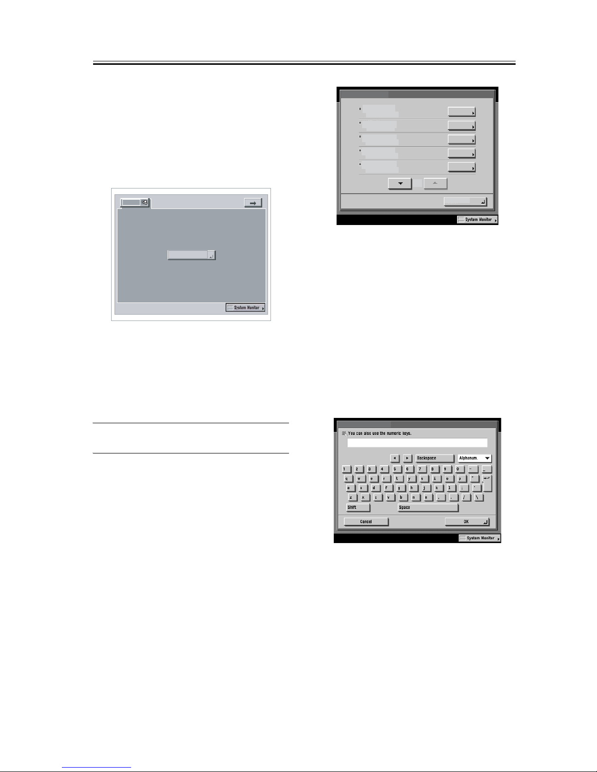
1) Press (=>) displayed at upper right on the LCD of
the connecting device.
2) At the Control Panel, press [Printer]tab.
3) Press [Printer Status/Settings].
Input of password
When setting it up, the password input screen is dis-
played.
When the following password is input, you can enter
a setup screen.
Fiery.1
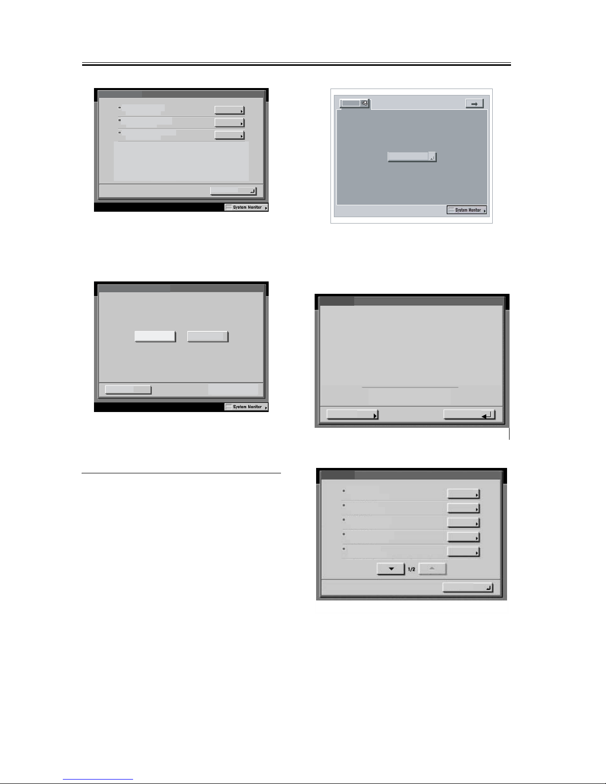
In response, the machine will automatically show the
Settings menu. Be sure to at least select the following
and make the appropriate settings in the indicated or-
der: [Server Setup], [Network Setup], and [Printer
Setup]. For more information, see Configuration and
Setup on the User Documentation.
For instance, once you have made the various settings
under [Server Setup], you will be shown a screen ask-
ing you if you want to store the settings. Select [yes]
so that the system will be stored in memory. Unless
you have made appropriate settings in the correct or-
der and saved them, you will not be able to go on to
the next item.
Making Server Settings:
Make the appropriate settings including the name
of the server.
Making Network Settings:
Make the appropriate settings including port,
protocol, and service.
Printer
Printer Status/
Settings
S
erve r Se tup
N
etwo rk Se tup
P
rinte r Setu p
P
S Setup
Run Setup
1/3
P
CL Setup
En te r Se rver Na me
PS_Server
Page 8
8
Making Printer Settings:
Make the appropriate settings including print
queue.
4) Select [close] on the Settings menu. In response, the
system will restart automatically.
1.2.4 Checking the Operation
After Making the Settings
Print out a test page and a settings page as follows to
make sure that all settings have correctly been made
on the machine and its host machine and that all con-
nections are normal:
1) Press (=>) displayed at upper right on the LCD of
the connecting device.
2) At the Control Panel, press [Print].
3) Press [Printer Status/Settings].
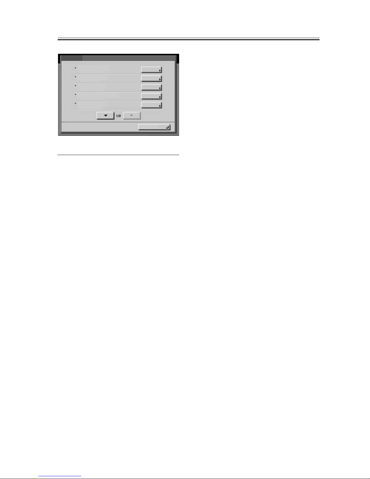
4) Make the following selections on the LCD:func-
tion>print page>test page/configuration.
N
etwork Setup
P
ort Setup
P
rotocol Setup
S
ervice Setup
OK
Y
es
N
o
P
ublish Direct Connection
Cancel
Printer
Printer Status/
Settings
PS Server-XX
Idle
FunctionsDone
Info
x.x
16936MB
Functions
Shut Down
D
n
Suspend
Scan Job
Print Pages
Resume Printing
Page 9
9
Print Pages
PS Font List
D
n
Job Lo
g
Configuration
PS Test Page
Color Charts
Page 10

10
1.3 Checking the Operation
1.3.1 Network connection
Ask the network administrator for network connec-
tion, settings and test print.
For more information, see Configuration and Setup on
the User Documentation.
Page 11
11
1.1 同梱部品の確認
1.1.1 同梱部品の確認
[1]
PS プリントサーバユニット 1 個
[2]
オープン I/F 回路基板 1 個
[3]
通信ケーブル 1 個
[4]
電源ケーブル 1 個
[5]
クロスイーサネットケーブル 1 個
[6]
ケーブルクランプ(角型) 4 個
[7]
段ビス 2 本
[8]
RSタイトビス(菊座付) 4本
[5] [6] [7]
[8]
[1] [2] [3] [4]
Page 12
12
1.2 設置手順
1.2.1 接続前の準備
■ iR C6870/C5870 本体にメモリが、1024 MB に
増設してあること。
RAM容量は、サービスモード
>COPIER>Display>ACC-STS>RAMにて確認でき
る。
注意:増設していない場合、E604 が点灯する。
■接続機器のサービスモード
COPIER>OPTION>INT-FACE>IMG-CONT を「3」
に設定しておくこと。(接続機器と本機間の通信
用 IP アドレスを自動で設定するモード)
■下図のように本機を設置するスペースを確保
する。本機の背面から 20cm 以上のスペースが必
要である。
1.2.2 接続機器への取付け
1. 本体の電源 OFF
主電源の切り方
主電源を切る際は、本製品のハードディスクを
保護するため以下の手順に従い行うこと。
1. 操作部電源スイッチを 3 秒以上押す。
2. シャットダウンシーケンスの画面表示に従い
タッチパネルを操作し、主電源スイッチをOFF
できる状態にする。
3. 主電源スイッチを OFF する。
4. 電源ケーブル ( コンセント用 ) を外す。
2. 設置手順
1) ケーブルをクランプから外す。
・クランプ[1]4ヶ所
・コネクタ[2]1 個
2) 後カバー(上)[1]を外す。
・ビス[2]7 本
3) コントローラボックスカバー[1]を外す。
・ビス[2]16 本
20 cm
[1]
[2]
[2]
[2]
[1]
Page 13
13
4)オープン I/F 回路基板の取付け準備を行う。
■本体に設置されているメインコントローラ回
路基板(サブ 0-A)を取外す。
ビス [1]2 本を外して、メインコントローラ回
路基板(サブ 0-A)[2] を取外す。(取外したビ
ス [1] は次の手順で使用する)
取外したメインコントローラ回路基板(サブ
0-A)はユーザーに渡し、保管して頂くこと。
5)外したビス [1] を使用して、同梱のオープン
I/F 回路基板 [2] を取付ける。
6) 手順 3) で外したコントロールボックスカバー
を取付ける。
7) 手順 2) で外した後カバー ( 上 ) を取付ける。
8) 手順 1) で外したケーブルを取付ける。
9)同梱の段ビス [1]2 本を後カバー ( 下 ) に取付
け、PS プリントサーバユニット [2] を掛ける。
10) 同梱の RS タイトビス [1]4 本で、PS プリン
トサーバユニット [2] を固定する。
[1]
[2]
[2]
[2]
[2]
[1]
[2]
[1]
[2]
[1]
[2]
Page 14
14
11) クランプ [1]4 個を取付ける。
12) 通信ケーブル [1] で、オープン I/F 回路基板
と PS プリントサーバユニットを接続する。
13) クロスイーサネットケーブル [1] で、PS プ
リントサーバユニットと接続機器とを接続す
る。
クロスイーサネットケーブルを接続するとき、
接続ポートの位置に注意する。
ユニットにはイーサネットケーブルの接続コネ
クタが 2 個ある。
iR 本体に接続するためのコネクタは、USB ポー
トから離れている側である。
USB ポートの隣にあるコネクタは、ネットワー
クケーブル用なので誤って接続しないように注
意する。
プリントサーバ接続パネル
[1]
[1]
[2]
[1]
[1]
Page 15
15
14) クロスイーサネットケーブルと通信ケーブ
ルをクランプ [1]4 個で束ねる。
15) 電源ケーブル [1] の一方を PS プリントサー
バユニットに、もう一方をコンセントに接続す
る。
16) 接続機器の電源ケーブル(コンセント用)
を接続する。
17) 接続機器の電源を ON にする。
- 接続機器上の液晶表示部上に、「[ シャットダウ
ン ] キーを押してシャットダウン処理後、本体右
側面の電源を入れ直してください。」が表示され
たら、[ シャットダウン ] のボタンを押す。
- 接続機器上の液晶表示部上に、「本体右側側面
の主電源を切ってください」が表示されたら、電
源を OFF する。10 秒後以降に電源を ON する。
1.2.3 本機の設定
1)接続機器の液晶表示部上の右上の矢印「⇒」
タブを押す。
2)液晶表示部左上の「プリンタ」タブを押す。
3)「プリンタ状況/設定」ボタンを押す。
パスワードの入力
設置時にパスワード入力画面が表示される。
下記パスワードを入力すると設定画面に入れ
る。
Fiery.1
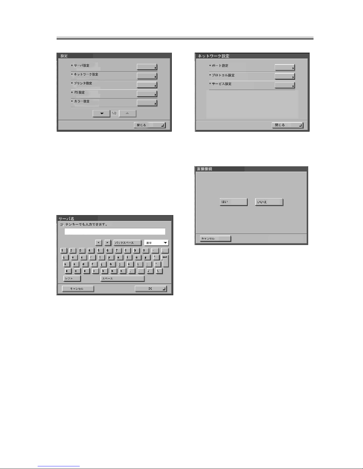
その後、自動的に「設定」メニューに入るので
最低「サーバ設定」、「ネットワーク設定」、「プ
リンタ設定」の各項目を順番に選択し、各々デー
タを保存する。詳細は、ユーザーマニュアルの
「設定管理」を参照する。
[1]
[1]
[1]
Page 16
16
例えば、「サーバ設定」の各項目を設定していく
と、最後に変更の保存をするかどうかを選択す
る画面が表示されるので、「はい」を選択すると、
その時の設定を保存することができる。各項目
を順番に選択して保存しないと次の項目を設定
できない。
サーバ設定:
サーバ名の設定等を行う。
ネットワーク設定:
ポート設定、プロトコル設定、サービス設定を
行う。
プリンタ設定:
印刷キューの設定を行う。
4) 「設定」メニューの「閉じる」を選択する。
その後、自動的に再起動が行われる。
PS_Server-G1
Page 17
17
1.3 設置後の動作確認
1.3.1 設定後の動作確認
以下の手順で、テストページ、設定ページを出
力し、接続機器と本機の接続および本機の設定
を確認する。
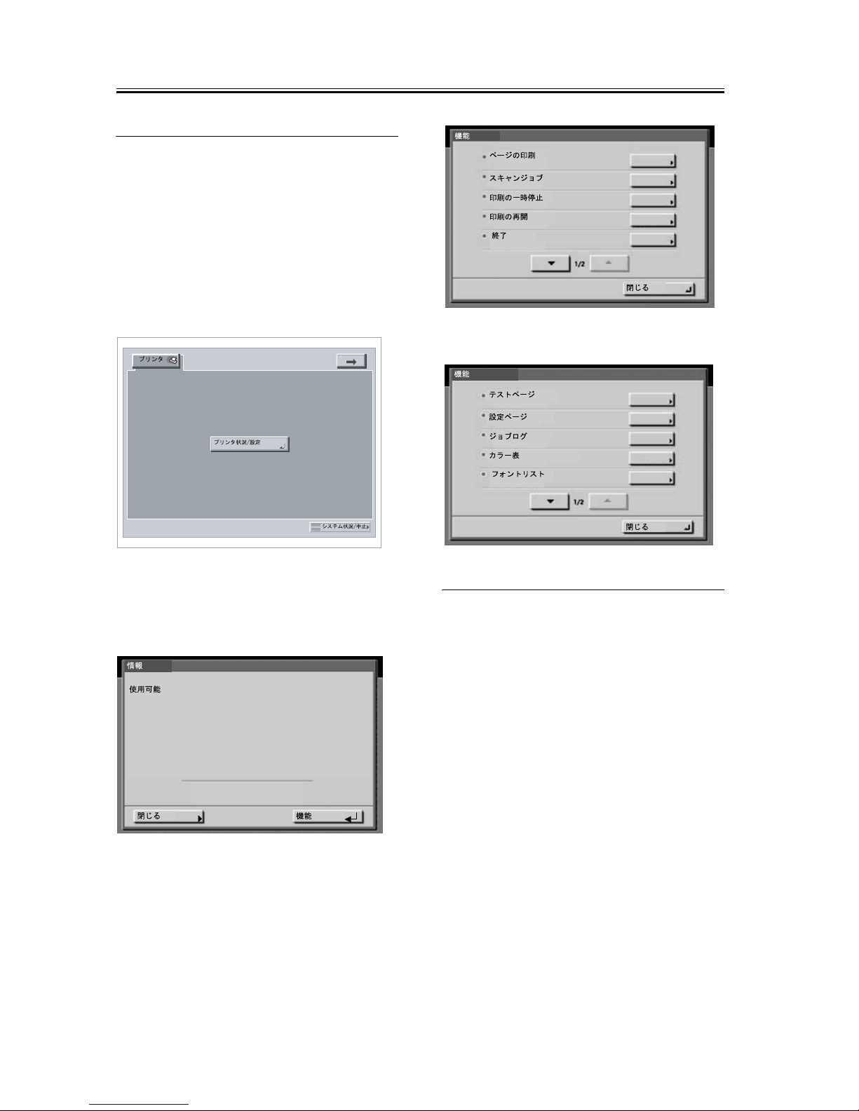
1 ) 接続機器の液晶表示部上の右上の矢印「⇒」
タブを押し、次に「プリンタ」タブを押す。
2 )「プリンタ状況/設定」ボタンを押す。
3 )「機能」-「ページの印刷」-「テストページ」
および「設定ページ」を選択する。
1.3.2 ネットワークへの接続
ネットワーク管理者にネットワークへの接続、
設定およびテストプリントを依頼する。
確認作業は、ユーザーマニュアルの「設定管理」
を参照して行う。
PS Server-G1
Soc. 014c
16936MB
 Loading...