

SERVICE
MANUAL
imageRUNNER
iR2270/2870/
3570/4570
Multi-PDL
Printer Kit-E1
COPYRIGHT 2004 CANON INC. CANON imageRUNNER Multi-PDL Printer Kit-E1 REV. 0 PRINTED IN U.S.A.
DU7-1133-000
SEPT. 2004
REV. 0

Application
This manual has been issued by Canon Inc. for qualified persons to learn technical theory, installation,
maintenance, and repair of products. This manual covers all localities where the products are sold. For
this reason, there may be information in this manual that does not apply to your locality.
Corrections
This manual may contain technical inaccuracies or typographical errors due to improvements or changes
in products. When changes occur in applicable products or in the contents of this manual, Canon will
release technical information as the need arises. In the event of major changes in the contents of this
manual over a long or short period, Canon will issue a new edition of this manual.
The following paragraph does not apply to any countries where such provisions are inconsistent with
local law.
Trademarks
The product names and company names used in this manual are the registered trademarks of the
individual companies.
Copyright
This manual is copyrighted with all rights reserved. Under the copyright laws, this manual may not be
copied, reproduced or translated into another language, in whole or in part, without the written consent
of Canon Inc.
COPYRIGHT © 2001 CANON INC.
Printed in Japan
Caution
Use of this manual should be strictly supervised to avoid disclosure of confidential information.
Introduction
Symbols Used
This documentation uses the following symbols to indicate special information:
Symbol Description
Indicates an item of a non-specific nature, possibly classified as Note,
Caution, or Warning.
Indicates an item requiring care to avoid electric shocks.
Indicates an item requiring care to avoid combustion (fire).
Indicates an item prohibiting disassembly to avoid electric shocks or
problems.
Indicates an item requiring disconnection of the power plug from the electric
outlet.
Memo
REF.
Indicates an item intended to provide notes assisting the understanding of the
topic in question.
Indicates an item of reference assisting the understanding of the topic in
question.
Provides a description of a service mode.
Provides a description of the nature of an error indication.

Introduction
The following rules apply throughout this Service Manual:
1. Each chapter contains sections explaining the purpose of specific functions and the
relationship between electrical and mechanical systems with reference to the timing of
operation.
In the diagrams, represents the path of mechanical drive; where a signal name
accompanies the symbol, the arrow indicates the direction of the electric
signal.
The expression "turn on the power" means flipping on the power switch, closing the front
door, and closing the delivery unit door, which results in supplying the machine with
power.
2. In the digital circuits, '1'is used to indicate that the voltage level of a given signal is
"High", while '0' is used to indicate "Low".(The voltage value, however, differs from
circuit to circuit.) In addition, the asterisk (*) as in "DRMD*" indicates that the DRMD
signal goes on when '0'.
In practically all cases, the internal mechanisms of a microprocessor cannot be checked
in the field. Therefore, the operations of the microprocessors used in the machines are
not discussed: they are explained in terms of from sensors to the input of the DC
controller PCB and from the output of the DC controller PCB to the loads.
The descriptions in this Service Manual are subject to change without notice for product
improvement or other purposes, and major changes will be communicated in the form of
Service Information bulletins.
All service persons are expected to have a good understanding of the contents of this
Service Manual and all relevant Service Information bulletins and be able to identify and
isolate faults in the machine."

Contents
Contents
Chapter 1 Specifications
1.1 Product composition .................................................................................................. 1-1
1.1.1 Product Composition (USA)............................................................................... 1-1
1.2 Specifications............................................................................................................. 1-2
1.2.1 Specifications ...................................................................................................... 1-2
1.2.2 PCL Printer Driver .............................................................................................. 1-3
1.2.3 PS Printer Driver ................................................................................................. 1-4
Chapter 2 Functions
2.1 New Function............................................................................................................. 2-1
2.1.1 Canon Driver Information Assist Service (DIAS) .............................................. 2-1
2.1.2 FTP Printing........................................................................................................ 2-3
2.1.3 PS-MODE ........................................................................................................... 2-6
2.1.4 Halftone Settings................................................................................................. 2-6
2.1.5 Secured Print Jobs ............................................................................................... 2-7
2.1.6 Up to 50 mm of Gutter...................................................................................... 2-11
2.1.7 Processing on System........................................................................................ 2-13
Chapter 3 Installation
3.1 Points to Note About Installation............................................................................... 3-1
3.1.1 Precaution for installation ................................................................................... 3-1
3.2 Checking components................................................................................................ 3-2
3.2.1 Checking the Contents ........................................................................................ 3-2
3.3 Installation procedure ................................................................................................ 3-4
3.3.1 Installation........................................................................................................... 3-4

Chapter 1
Specifications

Contents
Contents
1.1 Product composition...................................................................................1-1
1.1.1 Product Composition (USA) ...............................................................1-1
1.2 Specifications .............................................................................................1-2
1.2.1 Specifications ...................................................................................... 1-2
1.2.2 PCL Printer Driver ..............................................................................1-3
1.2.3 PS Printer Driver .................................................................................1-4
1.1 Product composition
Chapter 1
1.1.1 Product Composition (USA)
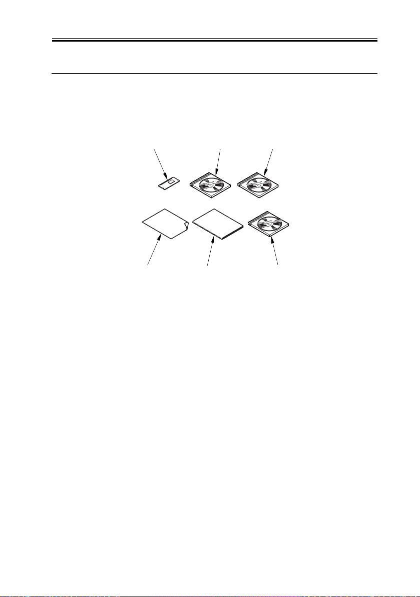
Multi-PDL Printer Kit-E1 USA
[1]
[4]
[1] Boot ROM (type N)..............................................................................1 pc.
[2] User Software CD-ROM Unit (English)..........................................1 pc.
[3] N/W ScanGear CD-ROM (English).................................................1 pc.
[4] Release Note (English)....................................................................1 pc.
[5] N/W Quick Start Guide (English).....................................................1 pc.
[6] User's Manual CD-ROM (English)..................................................1 pc.
[2]
[5]
F-1-1
[3]
[6]
0008-5248
1-1

Chapter 1
1.2 Specifications
1.2.1 Specifications
The main specifications and features of the kit are as shown below.
<Characteristics>
- printing is virtually immediate
- output is close to screen display
T-1-1
Specifications
Data processing
resolution
Effective print area
Supported operating
systems
PCL main scanning direction: 1/6 inch
PS3 main scanning direction: 2.5mm
600 dpi
sub scanning direction: 1/6 inch
sub scanning direction: 2.5mm
Windows 2000 Professional/Server/Advanced
Server
Windows XP Home Edition/Professional
Windows Server 2003 Stadard Edition/Enterprise
Edition
0008-5245
Windows 98/98SE/ME
Windows NT4.0 Workstation/Server
Paper size default papers
1-2

Non-default paper
T-1-2
User-defined paper
PCL minimum 90.53 mm× 131.53 mm
maximum 288.53 mm × 423.53 mm
Chapter 1
PS3
minimum
maximum
94.00 mm × 135.00 mm
292.00 mm × 427.00 mm
Note:
The value in parentheses indicates the area in
mm2.
- The height and width can be specified by 1/10 mm(Except US)or 1/100 inch(US).
- The height must be equal to or greater than width.
1-3

Chapter 1
1.2.2 PCL Printer Driver
FONT HANDLING:
・PCL5e/5c
HP-GL/2 Mode
Texts are handled in the PCL mode, or in the HP-GL/2 mode if:
1. Characters are clipped.
2.Characters are rotated.
Supported typefaces include:
1. Standard
2. Italic
3. Bold
4. Bold Italic
Raster Mode
Use of a device font is determined by the driver setting.
If a device font is used, the Raster Mode will handle data the same as the HP-GL/2
Mode.
If not, the following restrictions will be imposed.
*GDI Raster Fonts unavailable 1 byte fonts such as Courier, MS Sans Serif, MS
Serif, etc.
*GDI Vector Fonts available 1 byte fonts such as Modern, Roman, Script, etc.
*TrueType Fonts available 1 byte fonts such as Arial, Courier New, Symbol, Times
New Roman, etc.
0008-5666
・PCL6
PCL6 controls the texts if:
1.Characters are enlarged or reduced.
2.Characters are rotated.
3.Characters are clipped.
NOTE:
GDI Vector Fonts and TrueType Fonts become available only after added to Windows.
1-4

Chapter 1
1.2.3 PS Printer Driver
Target Printer:
Apple LaserWriter8500 for command
OKI MICROLINE800PS2LT for print quality
Target PDL:
Adobe PostScript Level3 3011
Note. Omit advanced feature of RedBook.
FONT HANDLING:
PS3
PostScript PDL boards support the following font types.
Type 0, 1, 2, 3, 4, 5, 6, 9, 10, 11, 14, 32 and 42
IDFontType 0, 1, 2 and 4
0008-5667
1-5

Chapter 2
Functions

Contents
Contents
2.1 New Function.............................................................................................2-1
2.1.1 Canon Driver Information Assist Service (DIAS) .............................. 2-1
2.1.2 FTP Printing........................................................................................2-3
2.1.3 PS-MODE ...........................................................................................2-6
2.1.4 Halftone Settings.................................................................................2-6
2.1.5 Secured Print Jobs ...............................................................................2-7
2.1.6 Up to 50 mm of Gutter......................................................................2-11
2.1.7 Processing on System........................................................................2-13

2.1 New Function
Chapter 2
2.1.1 Canon Driver Information Assist Service (DIAS)
This is a subset version of the Netspot Suite Service, supporting Driver only: we have
selected Driver's functions (mainly, the functions to acquire Device configuration
information) and redesigned them. The DIAS has the following functions:
- To acquire Device configuration information (acquisition when setting up Printer
Property.)
- To acquire calibration information (acquisition when setting up Printer Property and
printing by the color LBP, Color iR, and etc.)
- To make recognition in department-control printing (communication when setting up
Printer Property or when making a department-control print)
Main structure of DIAS
DIAS (DLL): It is a module loaded on Driver
DIAS (Service): It does a service of installation on printer server when using a shared
printer (resident process)
CBT: It is a module group to control a local port, such as Centronics Cable or USB
H-VDC: It is a module group which are needed for the driver function in DIAS.
Characteristics of DIAS
- Local printer can acquire the configuration information in DIAS (DLL) only.
Local printer means a printer that is "Peer to Peer" connected with Local PC via LPR/IPP/
Centronics Cable/USB and that Spooler (Print queue) appears on the Local PC.
0008-5246
- Shared printer needs to have DIAS (Service) installed on printer server.
The installation of DIAS (Service) must be done via Driver installer.
Shared printer means a printer whose Spooler (Print queue) appears on the printer server
(Remote PC).
- However, in some cases, DIAS (Service) needs to be installed for Local Port connection.
(See "Help" > "Troubleshoot the acquisition of configuration information".
1, WinNT4.0 OS Family (All)/ At the time of Local Port connection (LPT)
2, Win2k Server OS Family (Except Professional)/At the time of Local Port connection
2-1

(LPT/USB) and Terminal Service introduction
3, WinXP Home/Professional Edition/ServerOS 2003 Family (X86:All)/ At the time of
Local Port connection (LPT/USB) and Terminal Service introduction
About the version indication
The same Driver version indication as the one via Netspot Suite Service appears only when
communicating with Device via DIAS (Service) (i.e., when connected through a shared
printer).
Compatibility of DIAS and Netspot Suite Service
DIAS and Netspot Suite Service are compatible and independent. Driver supporting DIAS
does not use Netspot Suite Service even if it is installed.
Cautions when using DIAS
CBT controls all access to Local Port; both DIAS (DLL/Service) and NetSpot Suite Service
use CBT to access Local Port from the same PC.
CBT was installed only on Netspot Suite Service before; it is automatically uninstalled in
response to uninstalling the existing NetSpot Suite Service. Follow the procedures below
when uninstalling the former versions of NetSpot Suite Service v3.40 and when uninstalling
JobMonitor v4.20 and former.
- Reinstall DIAS after the uninstallation is complete. (Reinstallation of DIAS is enabled via
Installer.)
- Update NetSpot Suite Service to the latest version (v3.40 and later).
Former versions of NetSpot Suite Service v3.40
PS Printer Driver v2.10 and former
PCL5e Printer Driver v6.11 and former
PCL5c Printer Driver v6.11 and former
PCL6 Printer Driver v6.11 and former
UFR Printer Driver v1.10 and former
JobMonitor v4.10 and former
About a file name of the CBT module
Following files are installed in the 'c:\Windows\system' folder. (For Windows XP/Windows

Chapter 2
2000/NT/Server2003, this folder name is to be '%SystemRoot%\system32'.)
AuPort.exe
NBCBTNT.dll / NBCBT95.dll
NBPORTNT.exe / NBPORT95.exe
NBLOCALT.dll
nbcbtspt.dat
Method of confirming when CBT is deleted
The following message is displayed.
"Failed to obtain device information Make sure no printer error occurred and printout port
setting is correct."
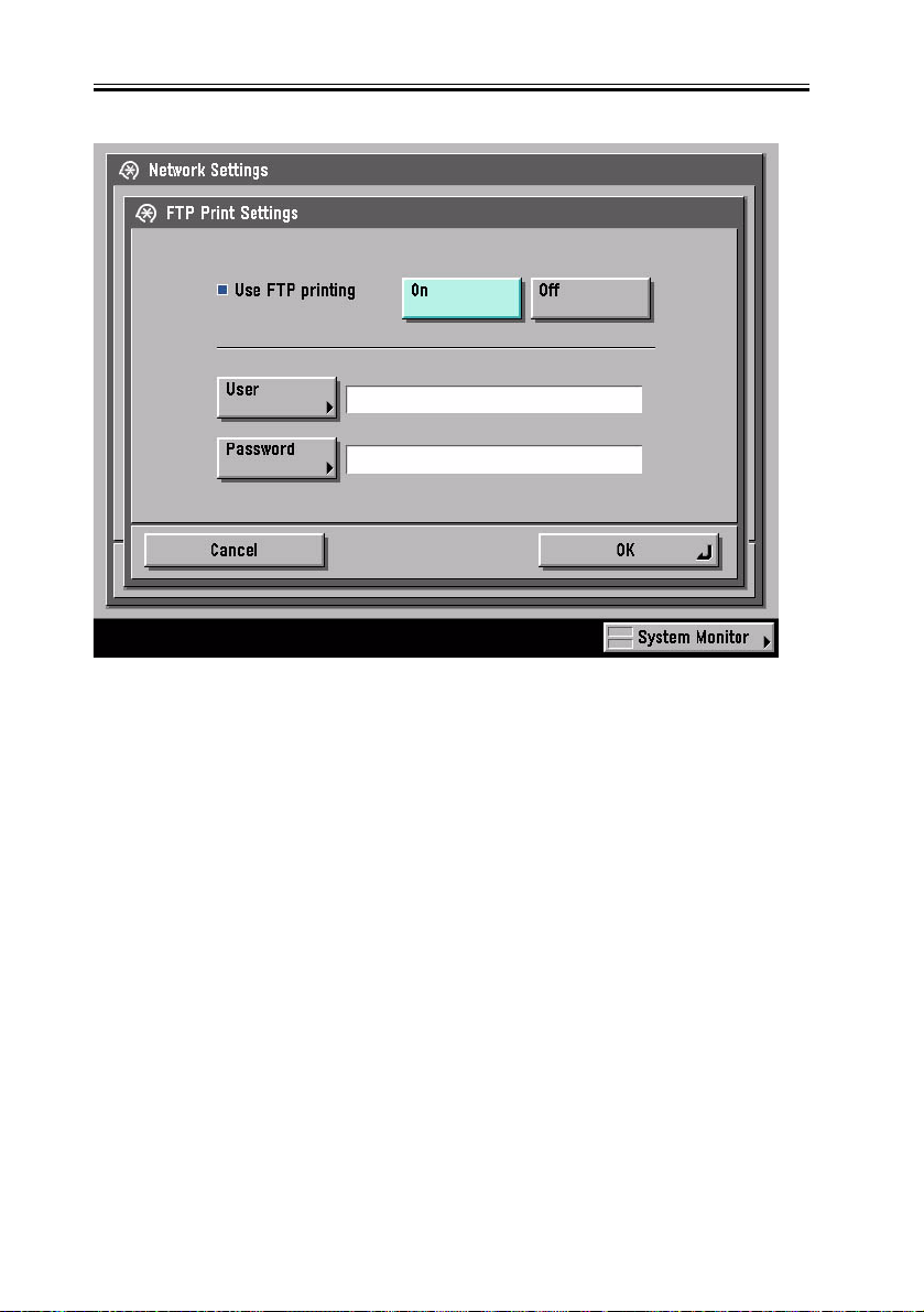
2.1.2 FTP Printing
This device provides a FTP server for receiving print data. The device can accept print jobs
sent in FTP from client PCs. This is called FTP printing, a new feature first employed on
iRC 6800. To use this feature, the FTP Print option must be selected. It is selected by
default. You can access the option by pressing Ad Func, System Settings, Network Settings,
TCP/IP Settings, and FTP Print Settings buttons. In FTP Print Settings screen, only one pair
of a user name and password can be entered for the user who can log in to the FTP server.
No settings are made for both of the fields by default.
0008-5247
2-3
Chapter 2
F-2-1
Commands
The FTP server complies with the RFC 959 -- File Transfer Protocol -- but provides only
printing function. Thus the server does not support other functions required as a RFC 959
compliant server. The commands available for the FTP client are "user," "password," "bin,"
"put," "bye," "hash," and "help." There is no use of other commands since the server does
not provide functions other than printing. The following lists the notes to use the
commands.
- To send print data with the command "put," set the mode to the binary mode using the
command "bin." In the ascii mode, the data cannot be sent with the command "put."
- If the user and password fields are blank, any user with any password can log in. If the
user name "anonymous" is used, any character string can be entered as the password. The
device displays the string in User filed of Log screen.
2-4

- This function is featured mainly to print prn files output from PDL drivers. The device
processes text files and the like as it receives data in LPR (and does not properly print
depending on settings.) The device of PostScript-compatible model can print PDF files,
compatible with PDF V1.3.
The following shows a command specification example, which you will connect the device
of the IP address "172.16.181.131" in FTP with the user name "test" and the password "test"
and print the file "test.prn" in the root directory of the drive C on the client PC.
C:\>ftp 172.16.181.131
Connected to 172.16.181.131.
220 Connection established.
User (172.16.181.131:(none)): test
331 Password required to login.
Password: Note: The password is not displayed.
230 User test logged in.
ftp> bin
200 Type set to IMAGE (binary).
ftp> put c:\test.prn
200 PORT command successful.
150 Opened BINARY data connection for file transfe
226 Transfer complete.
ftp: 15871 bytes sent in 0.00Seconds 15871000.00Kb
ftp> bye
221 Server closing down connection.
C:\>
Number of Connections and Used Ports
The maximum number of concurrent connections is three. If a user attempts to connect to
the FTP server with which three connections have been established, the user cannot log in
and fails in connection. The default port for the FTP server is 21. There is no measure
provided to change the port.
The control port time-out is set to 300 seconds. You need to re-connect to the server if you
Chapter 2
have left the connection for 300 seconds or more after logging in. The data port time-out is
60 minutes. If a data transmission takes more than 60 minutes, the connection is
automatically disconnected.
2.1.3 PS-MODE
Halftone compatibility for iR2200/3300/2800
PS3 Only - Service Mode Level 2
COPIER > OIPTION > USER > PS-MODE
0 = iR4570/3570/2870/2270
1 = iR2200/3300/2800
2.1.4 Halftone Settings
Halftone Settings (PS B&W printers)
0008-5388
0008-5390
F-2-2
2-6
Chapter 2
F-2-3
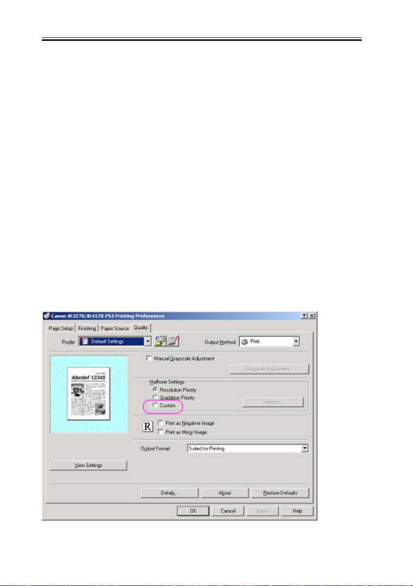
Only for monochrome PS printers, it will be possible to specify the halftone screen
frequency and angle.
For that, in the “Halftone Settings” section in the “Quality” tab, the “Custom” radio button
and the “Settings” buttonwill be provided.
The “Settings” button will be disabled by default and will be enabled by selecting the
“Custom” radio button.
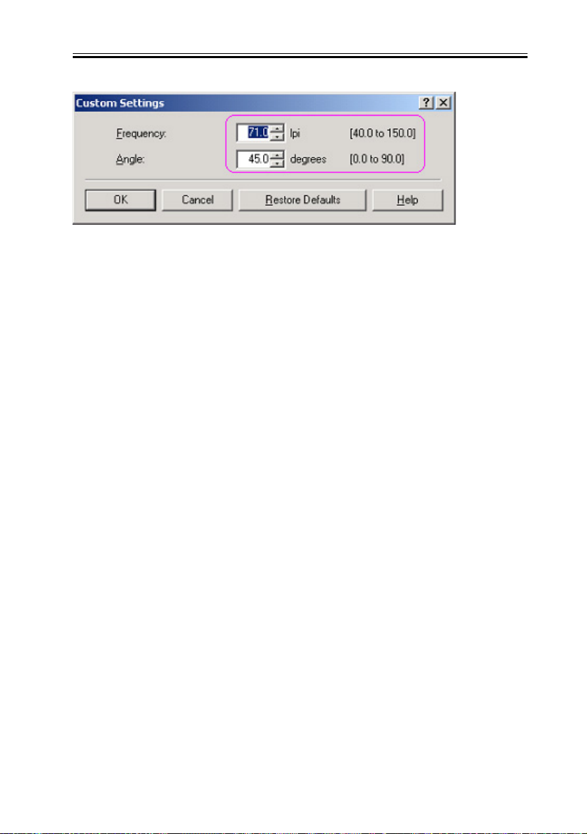
Clicking the “Settings” button will open the “Custom Settings” dialog to set the halftone
screen frequency and angle.
The “Frequency” spin box will default to a value of 71.0 and will accept a value between
40.0 and 150.0.
The “Angle” spin box will default to a value of 45.0 and will accept a value between 0.0
and 90.0.
2.1.5 Secured Print Jobs
Overview:
Secured Print is the function that a password is provided to the PDL print job and it is sent
to the device. Then, it is rasterized on the device side, saved in the image server and output
by entering the password from the device’s panel. This function is used when dealing with
the documents which you do not want other people to see, such as confidential documents.
a) Password is provided.
In order to conduct the Secured Print, the printer driver requires the user to enter the
password from GUI. This password is provided to the print job and it is sent to the device.
This function can be conducted by using CPCA protocol.
0008-5624
2-7

Chapter 2
b) Job execution and pending
PDL print job sent to the device as the Secured Print job is compiled on the job queue like
the normal PDL print job. Then, it is rasterized by PDL interpreter, saved in the image
server as the document image file and becomes pending here. However, all job information,
such as paper supply/output, the number of copies and finishing information remains.
c) Job started by entering the password
If the Secured Print job is pending, the display indicating the pending state appears on the
job status screen of the panel. If you select this job from the panel, you are required to enter
the password. When the password you entered is same as the password provided from the
printer driver, the pending job will be started. When the password is different, the job is
treated as an error, so it is not started and it remains in the pending state. Entering the
password to start the job cannot be executed before the Secured Print job transfers to the
pending state.
d) Output
The started Secured Print job is output to the printer engine with the top priority. This top
priority means that if the jobs can be changed in priority order, the Secured Print job can be
prioritized. This job is proceeded according to all job information specified by the printer
driver, etc., such as paper supply/output, the number of copies and finishing information.
When the processing is completed and all documents are output, the documents and job
information stored in the image server are deleted.
e) Operations for Secured Print jobs
Like other print jobs, Secured Print jobs can be deleted, interrupted, restarted and promoted
by operating from the status screen of the print job. Regarding these operations, the device
side does not distinguish from operations of the normal PDL job. That is, the password entry
is required only when the job is output. If you interrupt or restart the job during outputting,
the password setting and matching are not conducted.
f) Automatically delete of Secured Print Jobs
When Secured Print Job is continuing being suspended for a long time, apparatus deletes a
job automatically.
There are options for automatic job deletion time -- 1, 2, 3, 6, 12, and 24 hours. With a view
of security and memory usage, no option longer than 1 day is available. The elapsed time
starts after all the processes for the PDL data and the rendering for all the image data, for
2-8

which Secured Print is specified, are finished.
g) Specifications and Limitations on Secured Print Jobs
The limitations on Secured Print jobs are listed as follows.
- Once data of a Secured Print job is printed, it is immediately deleted and cannot be printed
any more.
- If the power for the controller is shut down, unprinted data of a Secured Print job is deleted
from the printer.
- All the job information, represented by the paper source and output information,
information of the number of copies, and finishing information, cannot be changed on the
printer.
- If the entire raster information for a Secured Print job cannot be stored in the image server
(hard disk drive) due to insufficient memory, the job results in an error, to be deleted.
- Up to 50 Secured Print jobs of image data being rendered and left unprinted can be stored.

F-2-4
F-2-5

F-2-6
Chapter 2
F-2-7
2.1.6 Up to 50 mm of Gutter
Up to 50 mm of the gutter can be specified. The gutter can be adjusted within a range from
0008-5626
2-11

Chapter 2
-50 mm to 50 mm in 1 mm increments. The local UI and the print driver have the controls
for the gutter settings.
The image is shifted to the width value specified for gutter, making a margin. If the shift
causes the image to overflow from the printable area, the overflowing area is missing from
the print results. The overflowing image will not be reduced to fit into the printable area.
F-2-8
F-2-9
The gutter width range changed to 0-50 mm.
2-12

US: 0.0 to 2.0 inches
UK: 0.0 to 50.0 mm
Chapter 2
2.1.7 Processing on System
Processing after Power Shutdown
If the power is shut down during PDL data processing, all the image data temporarily stored
in the hard disk drive to be printed or stored in Mail Boxes are destroyed and the jobs are
canceled. PDL data stored in the hard disk drive immediately before a power shutdown are
destroyed as the power is shut down. Processing the data of those, therefore, will not resume
when the power is turned on after the shutdown. Jobs interrupted by a power shutdown will
be displayed in the Log list with the End Code “NG (#852).”
0008-5622
2-13

Chapter 3
Parts
Procedure
Replacement

Contents
Contents
3.1 Points to Note About Installation ...............................................................3-1
3.1.1 Precaution for installation ...................................................................3-1
3.2 Checking components ................................................................................3-2
3.2.1 Checking the Contents ........................................................................ 3-2
3.3 Installation procedure.................................................................................3-4
3.3.1 Installation...........................................................................................3-4

3.1 Points to Note About Installation
Chapter 3
3.1.1 Precaution for installation
To install the Kit, you will need a separately available expansion RAM (256 MB) (Except
USA).
0007-7266
3-1

Chapter 3
3.2 Checking components
3.2.1 Checking the Contents
Multi-PDL Printer Kit-E1 USA
[1]
[4]
[1] Boot ROM (type N)..............................................................................1 pc.
[2] User Software CD-ROM Unit (English)..........................................1 pc.
[3] N/W ScanGear CD-ROM (English).................................................1 pc.
[4] Release Note (English)....................................................................1 pc.
[5] N/W Quick Start Guide (English).....................................................1 pc.
[6] User's Manual CD-ROM (English)..................................................1 pc.
Multi-PDL Printer Kit-E1 EUR/OTH
[2]
[5]
F-3-1
[3]
[6]
0007-7268
3-2

Chapter 3
[3]
[6]
[4]
[1]
[2]
[5]
F-3-2
[1] BootROM (type N)............................................................................................1 pc.
[2] User Software CD-ROM Unit (English, French, German, Italian, Spanish).....1 pc.
[3] N/W ScanGear CD-ROM (English, French, German, Italian, Spanish)............1 pc.
[4] Release Note (English, French, German, Italian)...............................................1 pc.
[5] N/W Quick Start Guide (English, French, German, Italian)..............................1 pc.
[6] User's Manual CD-ROM (English, French, German, Italian)............................1 pc.
3-3

Chapter 3
3.3 Installation procedure
3.3.1 Installation
0007-7276
1. Turning Off the Host Machine
Before starting the work, be sure to perform the following on the host machine in strict
order:
1. Hold down on the control panel power switch for 3 sec or more.
2. Go through the instructions indicated on the control panel touch panel (for shutdown
sequence) so that the host machine's main power switch may be turned off.
3. Turn off the main power switch.
4. Disconnect the power cable (from the wall outlet).
[1]
ON/OFF
3-4
[3][2]
F-3-3
[4]

2. Installation
1) Remove the 4 screws [1].
2) Loosen the 2 screws [2].
[1]
[1]
[2]
F-3-4
3) Pull the face cover [1] in upward direction to detach.
Chapter 3
[1]
F-3-5
3-5

Chapter 3
4) Push the locking lever [1] to detach the boot ROM [2].
F-3-6
5) Fit the included boot ROM [1] in place.
F-3-7
6) Attach the face cover using 4 screws.
7) Tighten the 2 screws loosened in step 2).
8) Connect the host machine's power cable (to the wall outlet).
9) Turn on the main power swish.
3. Checking the Installation
Make the following selections, and check the state of the following bits: COPIER >
ACC-STS > PDL-FNC1.
111x xxxx xxxx xxxx (0: OFF; 1: ON)
In the case of the PDL-FNC1, bits 31 through bits 16 are indicated.
Be sure that the following bits are '1': 31, 30, 29.
3-6


SERVICE
MANUAL
imageRUNNER
iR2270/2870/
3570/4570
UFRII
Printer Kit-E3
COPYRIGHT 2004 CANON INC. CANON imageRUNNER UFRII Printer Kit-E3 REV. 0 PRINTED IN U.S.A.
DU7-1133-000
SEPT. 2004
REV. 0

Application
This manual has been issued by Canon Inc. for qualified persons to learn technical theory, installation,
maintenance, and repair of products. This manual covers all localities where the products are sold. For
this reason, there may be information in this manual that does not apply to your locality.
Corrections
This manual may contain technical inaccuracies or typographical errors due to improvements or changes
in products. When changes occur in applicable products or in the contents of this manual, Canon will
release technical information as the need arises. In the event of major changes in the contents of this
manual over a long or short period, Canon will issue a new edition of this manual.
The following paragraph does not apply to any countries where such provisions are inconsistent with
local law.
Trademarks
The product names and company names used in this manual are the registered trademarks of the
individual companies.
Copyright
This manual is copyrighted with all rights reserved. Under the copyright laws, this manual may not be
copied, reproduced or translated into another language, in whole or in part, without the written consent
of Canon Inc.
COPYRIGHT © 2001 CANON INC.
Printed in Japan
Caution
Use of this manual should be strictly supervised to avoid disclosure of confidential information.

Introduction
Symbols Used
This documentation uses the following symbols to indicate special information:
Symbol Description
Indicates an item of a non-specific nature, possibly classified as Note,
Caution, or Warning.
Indicates an item requiring care to avoid electric shocks.
Indicates an item requiring care to avoid combustion (fire).
Indicates an item prohibiting disassembly to avoid electric shocks or
problems.
Indicates an item requiring disconnection of the power plug from the electric
outlet.
Memo
REF.
Indicates an item intended to provide notes assisting the understanding of the
topic in question.
Indicates an item of reference assisting the understanding of the topic in
question.
Provides a description of a service mode.
Provides a description of the nature of an error indication.

Introduction
The following rules apply throughout this Service Manual:
1. Each chapter contains sections explaining the purpose of specific functions and the
relationship between electrical and mechanical systems with reference to the timing of
operation.
In the diagrams, represents the path of mechanical drive; where a signal name
accompanies the symbol, the arrow indicates the direction of the electric
signal.
The expression "turn on the power" means flipping on the power switch, closing the front
door, and closing the delivery unit door, which results in supplying the machine with
power.
2. In the digital circuits, '1'is used to indicate that the voltage level of a given signal is
"High", while '0' is used to indicate "Low".(The voltage value, however, differs from
circuit to circuit.) In addition, the asterisk (*) as in "DRMD*" indicates that the DRMD
signal goes on when '0'.
In practically all cases, the internal mechanisms of a microprocessor cannot be checked
in the field. Therefore, the operations of the microprocessors used in the machines are
not discussed: they are explained in terms of from sensors to the input of the DC
controller PCB and from the output of the DC controller PCB to the loads.
The descriptions in this Service Manual are subject to change without notice for product
improvement or other purposes, and major changes will be communicated in the form of
Service Information bulletins.
All service persons are expected to have a good understanding of the contents of this
Service Manual and all relevant Service Information bulletins and be able to identify and
isolate faults in the machine."

Contents
Contents
Chapter 1 Specifications
1.1 Product composition .................................................................................................. 1-1
1.1.1 Product Composition (USA)............................................................................... 1-1
1.2 Specifications............................................................................................................. 1-2
1.2.1 Specification........................................................................................................ 1-2
1.2.2 UFR II Printer Driver .......................................................................................... 1-3
Chapter 2 Functions
2.1 New Function............................................................................................................. 2-1
2.1.1 Flow of Image Data ............................................................................................ 2-1
2.1.2 Canon Driver Information Assist Service (DIAS) .............................................. 2-1
2.1.3 FTP Printing........................................................................................................ 2-3
2.1.4 Secured Print Jobs ............................................................................................... 2-6
2.1.5 Up to 50 mm of Gutter...................................................................................... 2-10
2.1.6 Load Balancing ................................................................................................. 2-12
2.1.7 Processing on System........................................................................................ 2-13
2.1.8 Sleep Processing ............................................................................................... 2-13
Chapter 3 Installation
3.1 Points to Note About Installation............................................................................... 3-1
3.1.1 Precaution for installation ................................................................................... 3-1
3.2 Checking components................................................................................................ 3-2
3.2.1 Checking the Contents(USA).............................................................................. 3-2

Chapter 1
Specifications

Contents
Contents
1.1 Product composition...................................................................................1-1
1.1.1 Product Composition (USA) ...............................................................1-1
1.2 Specifications .............................................................................................1-2
1.2.1 Specification........................................................................................1-2
1.2.2 UFR II Printer Driver ..........................................................................1-3

1.1 Product composition
Chapter 1
1.1.1 Product Composition (USA)
UFR II Printer Kit-E3
[1]
[4]
[1] BOOT ROM(type P)................................1 pc.
[2] User Software CD-ROM..........................1 pc.
[3] N/W ScanGear CD-ROM.........................1 pc.
[4] Release Note.............................................1 pc.
[5] N/W Quick Start Guide.............................1 pc.
[6] User Manual CD-ROM.............................1 pc.
[2]
[5]
F-1-1
0008-5508
[3]
[6]
1-1

Chapter 1
1.2 Specifications
1.2.1 Specification
0008-5607
The UFR II assigns print processing loads to the print driver and the print controller for
high-speed, low-cost outputs.
Advantages
- While the features are enhanced, the memory usage can be saved supporting both page and
band descriptions.
- Balancing the data processing loads of the driver and controller allows high-speed outputs.
T-1-1
Specification
UFR II
Data processing
600dpi
Effective print main scanning:2.5mm
Supported
operating systems
sub scanning:2.5mm
Windows 2000 Professional/Server/Advanced Server
Windows XP Home Edition/Professional
Windows Server 2003 Standard Edition/Enterprise Edition
Paper size default papaers
The UFR II print driver requires 2.5 mm of the top, bottom, left, and right margins.
1-2

Chapter 1
F-1-2
-Even if Print with Upper Left of Sheet as Starting Point option is selected, marginal areas
of the data for a page are missing in some print results. To solve this problem, adjust the
scaling so that the data fit into the printable area and print the data again.
1.2.2 UFR II Printer Driver
Support Environment (OS/Software)
Windows 2000 Professional/Server
Windows XP Home Edition/Professional
Windows Sever 2003 (32bit edition)
T-1-2
Windows 2000 Professional/Server
CPU Intel Pentium 133MHz or better processor
Memory32MB or larger (Professional) / 128MB or larger (Server)
HDD 850MB or larger (Professional) / 1GB or larger (Server)
0008-5512
1-3

Chapter 1
CPU Intel Pentium 233MHz or better processor
Memory64MB or larger
HDD 1.5GB or larger
CPU Intel Pentium 233MHz or better processor
Memory256MB or larger
HDD 1.5GB or larger
Windows XP Home Edition/Professional Edition
Windows Server 2003 Standard Edition/Enterprise Edition
Font Handling:
Device fonts are not used as the printing uses the UFR II driver.
GDI raster fonts cannot be used – e.g.,
One Byte - Courier, MS Sans Serif, and MS Serif.
Two Byte - FixedSys、System、Small Fonts、Terminal
GDI vector fonts can be used – e.g.,
One Byte - Modern, Roman, and Script.
TureType fonts can be used – e.g.,
One Byte - Arial、Courier New、Symbol、Times New Roman
Note.
Each font becomes usable by the font addition to Windows.
Paper Size:
1-4

T-1-3
Paper Name Paper Size (mm)
Width length
A3 297.0 420.0
A4 210.0 297.0
A5 148.5 210.0
11 x 17 279.4 431.8
LEGAL 215.9 355.6
LETTER 215.9 279.4
STATEMENT 139.7 215.9
EXECUTIVE 184.2 266.7
EXEC 184.2 266.7
COM10 104.7 241.3
MONARCH 98.4 190.5
ISO-C5 162.0 229.0
Chapter 1
ISO-B5 176.0 220.0
Non-default paper:
T-1-4
User-defined paper
UFR II minimum 140.0 mm × 182.0 mm
maximum 297.0 mm × 432.0 mm
- The height must be equal to or greater than width.
Area-Specific Paper Sizes:
In addition to default paper sizes (A4/LTR) and user-defined paper sizes, the printer driver
supports area-specific paper sizes (e.g., Officio), and it handles these area-specific paper
sizes as user-defined paper sizes, requiring the user to register them in advance of use. To
1-5

Chapter 1
do so, see the instructions on registering user-defined paper sizes for individual operating
systems.
When an area-specific paper size is manually set up under [Form to Tray Assignment] of
the driver UI, or if the size obtained by running dynamic configuration happens to be an
area-specific paper size, the driver operates in the corresponding mode. After performing
all associated internal operations, the driver runs a check of area-specific paper sizes stored
as user defined paper sizes, and handles any matching paper as a default paper size (special
paper ID) instead of as a user-defined paper size. Moreover, the driver permits registration
of multiple area-specific paper sizes, treating them as a separate paper group. The driver UI
handles them using specifications designed for LTR paper, permitting the use of finisher
functions, which were previously offered for user-defined paper sizes (except the use of the
middle binding function). Although it will permit all settings, the printer unit may ignore
some of the settings. (The printer driver will simply ignore them, not issuing conflicts.)
T-1-5
Paper size
Govermment Letter
Govermment Legal
Foolscap
Australian Foolscap
Oficio
Folio
Ecuadorian Oficio
Aegentine Oficio
Argentine Letter
Bolivian Oficio
Mexican Oficio
Supported Paper Types:
1-6
Dimensions
Feed
Direction
G_LTR 267.0 203.0
G_LBL
FLSP 330.0 216.0
A_FLSP
OFI 317.0 216.0
FOLIO 330.0 210.0
E_OFI 320.0 220.0
A_OFI 340.0 220.0
A_LTR 220.0 280.0
B_OFI 355.0 216.0
M_OFI 341.0 216.0
330.0 267.0
337.0 206.0
Width

Paper Type Paper Size
Chapter 1
T-1-6
PLAIN
COLOR
A3,B4,A4/A4R,B5,B5R,A5R,11x17,LGL.LTR/
LTRR,STMTR,EXEC,Officio,User-defined paper
RECYCLED
PREPUNCHED
HEAVY
BOND
A3,B4,A4/A4R,B5,B5R,A5R,11x17,LGL.LTR/
LTRR,STMTR,EXEC,User-defined paper
LABELS
Tracing Paper
OHP A4,LTR
ENVELOPE COM10,MONARCH,C5ISO,B5ISO,DL
Finishing:
T-1-7
Finisher Rotate Shift Staple Punch Saddle
None OK N/A N/A N/A N/A
Inner2way Tray OK N/A N/A N/A N/A
Finisher-S1 N/A OK OK OK N/A
Finisher-Q3 N/A OK OK OK N/A
Saddle Finisher-Q4 N/A OK OK OK OK
N/A : not available
1-7

Chapter 2
Functions

Contents
Contents
2.1 New Function.............................................................................................2-1
2.1.1 Flow of Image Data ............................................................................2-1
2.1.2 Canon Driver Information Assist Service (DIAS) .............................. 2-1
2.1.3 FTP Printing........................................................................................2-3
2.1.4 Secured Print Jobs ...............................................................................2-6
2.1.5 Up to 50 mm of Gutter......................................................................2-10
2.1.6 Load Balancing .................................................................................2-12
2.1.7 Processing on System........................................................................2-13
2.1.8 Sleep Processing................................................................................2-13

2.1 New Function
Chapter 2
2.1.1 Flow of Image Data
0008-5592
The following is a diagram showing the flow of image data:
[ PS/PCL Image Data Flow ]
LIPS LX
Driver
PC
Controller
UFR II
interpreter
Work
Memory
DL
Memory
Renderer
Page
Spool
Memory
ENGINE
F-2-1
2.1.2 Canon Driver Information Assist Service (DIAS)
0008-5590
This is a subset version of the Netspot Suite Service, supporting Driver only: we have
selected Driver's functions (mainly, the functions to acquire Device configuration
information) and redesigned them. The DIAS has the following functions:
- To acquire Device configuration information (acquisition when setting up Printer
Property.)
- To acquire calibration information (acquisition when setting up Printer Property and
printing by the color LBP, Color iR, and etc.)
- To make recognition in department-control printing (communication when setting up
Printer Property or when making a department-control print)
Main structure of DIAS
DIAS (DLL): It is a module loaded on Driver
DIAS (Service): It does a service of installation on printer server when using a shared
printer (resident process)
CBT: It is a module group to control a local port, such as Centronics Cable or USB
H-VDC: It is a module group which are needed for the driver function in DIAS.
2-1

Chapter 2
Characteristics of DIAS
- Local printer can acquire the configuration information in DIAS (DLL) only.
Local printer means a printer that is "Peer to Peer" connected with Local PC via LPR/IPP/
Centronics Cable/USB and that Spooler (Print queue) appears on the Local PC.
- Shared printer needs to have DIAS (Service) installed on printer server.
The installation of DIAS (Service) must be done via Driver installer.
Shared printer means a printer whose Spooler (Print queue) appears on the printer server
(Remote PC).
- However, in some cases, DIAS (Service) needs to be installed for Local Port connection.
(See "Help" > "Troubleshoot the acquisition of configuration information".
1, WinNT4.0 OS Family (All)/ At the time of Local Port connection (LPT)
2, Win2k Server OS Family (Except Professional)/At the time of Local Port connection
(LPT/USB) and Terminal Service introduction
3, WinXP Home/Professional Edition/ServerOS 2003 Family (X86:All)/ At the time of
Local Port connection (LPT/USB) and Terminal Service introduction
About the version indication
The same Driver version indication as the one via Netspot Suite Service appears only when
communicating with Device via DIAS (Service) (i.e., when connected through a shared
printer).
Compatibility of DIAS and Netspot Suite Service
DIAS and Netspot Suite Service are compatible and independent. Driver supporting DIAS
does not use Netspot Suite Service even if it is installed.
Cautions when using DIAS
CBT controls all access to Local Port; both DIAS (DLL/Service) and NetSpot Suite Service
use CBT to access Local Port from the same PC.
CBT was installed only on Netspot Suite Service before; it is automatically uninstalled in
response to uninstalling the existing NetSpot Suite Service. Follow the procedures below
when uninstalling the former versions of NetSpot Suite Service v3.40 and when uninstalling
JobMonitor v4.20 and former.
2-2

Chapter 2
- Reinstall DIAS after the uninstallation is complete. (Reinstallation of DIAS is enabled via
Installer.)
- Update NetSpot Suite Service to the latest version (v3.40 and later).
Former versions of NetSpot Suite Service v3.40
PS Printer Driver v2.10 and former
PCL5e Printer Driver v6.11 and former
PCL5c Printer Driver v6.11 and former
PCL6 Printer Driver v6.11 and former
UFR Printer Driver v1.10 and former
JobMonitor v4.10 and former
About a file name of the CBT module
Following files are installed in the 'c:\Windows\system' folder. (For Windows XP/Windows
2000/NT/Server2003, this folder name is to be '%SystemRoot%\system32'.)
AuPort.exe
NBCBTNT.dll / NBCBT95.dll
NBPORTNT.exe / NBPORT95.exe
NBLOCALT.dll
nbcbtspt.dat
Method of confirming when CBT is deleted
The following message is displayed.
"Failed to obtain device information Make sure no printer error occurred and printout port
setting is correct."
2.1.3 FTP Printing
This device provides a FTP server for receiving print data. The device can accept print jobs
sent in FTP from client PCs. This is called FTP printing, a new feature first employed on
iRC 6800. To use this feature, the FTP Print option must be selected. It is selected by
default. You can access the option by pressing Ad Func, System Settings, Network Settings,
TCP/IP Settings, and FTP Print Settings buttons. In FTP Print Settings screen, only one pair
of a user name and password can be entered for the user who can log in to the FTP server.
No settings are made for both of the fields by default.
0008-5591
2-3

Chapter 2
F-2-2
Commands
The FTP server complies with the RFC 959 -- File Transfer Protocol -- but provides only
printing function. Thus the server does not support other functions required as a RFC 959
compliant server. The commands available for the FTP client are "user," "password," "bin,"
"put," "bye," "hash," and "help." There is no use of other commands since the server does
not provide functions other than printing. The following lists the notes to use the
commands.
- To send print data with the command "put," set the mode to the binary mode using the
command "bin." In the ascii mode, the data cannot be sent with the command "put."
- If the user and password fields are blank, any user with any password can log in. If the
user name "anonymous" is used, any character string can be entered as the password. The
device displays the string in User filed of Log screen.
2-4

Chapter 2
- This function is featured mainly to print prn files output from PDL drivers. The device
processes text files and the like as it receives data in LPR (and does not properly print
depending on settings.) The device of PostScript-compatible model can print PDF files,
compatible with PDF V1.3.
The following shows a command specification example, which you will connect the device
of the IP address "172.16.181.131" in FTP with the user name "test" and the password "test"
and print the file "test.prn" in the root directory of the drive C on the client PC.
C:\>ftp 172.16.181.131
Connected to 172.16.181.131.
220 Connection established.
User (172.16.181.131:(none)): test
331 Password required to login.
Password: Note: The password is not displayed.
230 User test logged in.
ftp> bin
200 Type set to IMAGE (binary).
ftp> put c:\test.prn
200 PORT command successful.
150 Opened BINARY data connection for file transfe
226 Transfer complete.
ftp: 15871 bytes sent in 0.00Seconds 15871000.00Kb
ftp> bye
221 Server closing down connection.
C:\>
Number of Connections and Used Ports
The maximum number of concurrent connections is three. If a user attempts to connect to
the FTP server with which three connections have been established, the user cannot log in
and fails in connection. The default port for the FTP server is 21. There is no measure
provided to change the port.
The control port time-out is set to 300 seconds. You need to re-connect to the server if you
2-5

Chapter 2
have left the connection for 300 seconds or more after logging in. The data port time-out is
60 minutes. If a data transmission takes more than 60 minutes, the connection is
automatically disconnected.
2.1.4 Secured Print Jobs
Overview:
Secured Print is the function that a password is provided to the PDL print job and it is sent
to the device. Then, it is rasterized on the device side, saved in the image server and output
by entering the password from the device’s panel. This function is used when dealing with
the documents which you do not want other people to see, such as confidential documents.
a) Password is provided.
In order to conduct the Secured Print, the printer driver requires the user to enter the
password from GUI. This password is provided to the print job and it is sent to the device.
This function can be conducted by using CPCA protocol.
b) Job execution and pending
PDL print job sent to the device as the Secured Print job is compiled on the job queue like
the normal PDL print job. Then, it is rasterized by PDL interpreter, saved in the image
server as the document image file and becomes pending here. However, all job information,
such as paper supply/output, the number of copies and finishing information remains.
c) Job started by entering the password
If the Secured Print job is pending, the display indicating the pending state appears on the
job status screen of the panel. If you select this job from the panel, you are required to enter
the password. When the password you entered is same as the password provided from the
printer driver, the pending job will be started. When the password is different, the job is
treated as an error, so it is not started and it remains in the pending state. Entering the
password to start the job cannot be executed before the Secured Print job transfers to the
pending state.
0008-5624
d) Output
The started Secured Print job is output to the printer engine with the top priority. This top
priority means that if the jobs can be changed in priority order, the Secured Print job can be
prioritized. This job is proceeded according to all job information specified by the printer
2-6

Chapter 2
driver, etc., such as paper supply/output, the number of copies and finishing information.
When the processing is completed and all documents are output, the documents and job
information stored in the image server are deleted.
e) Operations for Secured Print jobs
Like other print jobs, Secured Print jobs can be deleted, interrupted, restarted and promoted
by operating from the status screen of the print job. Regarding these operations, the device
side does not distinguish from operations of the normal PDL job. That is, the password entry
is required only when the job is output. If you interrupt or restart the job during outputting,
the password setting and matching are not conducted.
f) Automatically delete of Secured Print Jobs
When Secured Print Job is continuing being suspended for a long time, apparatus deletes a
job automatically.
There are options for automatic job deletion time -- 1, 2, 3, 6, 12, and 24 hours. With a view
of security and memory usage, no option longer than 1 day is available. The elapsed time
starts after all the processes for the PDL data and the rendering for all the image data, for
which Secured Print is specified, are finished.
g) Specifications and Limitations on Secured Print Jobs
The limitations on Secured Print jobs are listed as follows.
- Once data of a Secured Print job is printed, it is immediately deleted and cannot be printed
any more.
- If the power for the controller is shut down, unprinted data of a Secured Print job is deleted
from the printer.
- All the job information, represented by the paper source and output information,
information of the number of copies, and finishing information, cannot be changed on the
printer.
- If the entire raster information for a Secured Print job cannot be stored in the image server
(hard disk drive) due to insufficient memory, the job results in an error, to be deleted.
2-7

Chapter 2
- Up to 50 Secured Print jobs of image data being rendered and left unprinted can be stored.
F-2-3
2-8

F-2-4
Chapter 2
2-9

Chapter 2
F-2-5
F-2-6
2-10

Chapter 2
2.1.5 Up to 50 mm of Gutter
Up to 50 mm of the gutter can be specified. The gutter can be adjusted within a range from
-50 mm to 50 mm in 1 mm increments. The local UI and the print driver have the controls
for the gutter settings.
The image is shifted to the width value specified for gutter, making a margin. If the shift
causes the image to overflow from the printable area, the overflowing area is missing from
the print results. The overflowing image will not be reduced to fit into the printable area.
F-2-7
0008-5626
F-2-8
2-11

Chapter 2
The gutter width range changed to 0-50 mm.
US: 0.0 to 2.0 inches
UK: 0.0 to 50.0 mm
2.1.6 Load Balancing
0008-5627
The UFR II is designed to balance the loads of the print driver and the controller of the
printer for optimized processing.
The UFR II assigns each processes depending on performances of the print driver and the
OS of the host.
On Windows 2000 and XP, a page can be divided into bands to transfer data to the
controller. In the controller, the data are processed by band all through the processes ending
with the Spool Memory.
Application
GDI
UFR II
driver
Spooler
Load Balance & Band Sort
Load Balance & Band Sort
band mode-
UFR II
IF
<Int erpret>
UFR II
interpreter
<Render> <Compress>
Display List
Band
Memory
Band Spool
Band Spool
Spool Memory
Eng-
ine
F-2-9
On Mac OS X, the print driver transfers data by page and the controller can process them
by band.
2-12

Chapter 2
<Render> <Compress>
Band
Spool Memory
Memory
Eng-
ine
Application
GDI
UFR II
driver
Spooler
page mode-
UFR II
Load Balance
Load Balance
IF
<Interpret >
UFR II
inter-
preter
Displ ay List
F-2-10
2.1.7 Processing on System
0008-5622
Processing after Power Shutdown
If the power is shut down during PDL data processing, all the image data temporarily stored
in the hard disk drive to be printed or stored in Mail Boxes are destroyed and the jobs are
canceled. PDL data stored in the hard disk drive immediately before a power shutdown are
destroyed as the power is shut down. Processing the data of those, therefore, will not resume
when the power is turned on after the shutdown. Jobs interrupted by a power shutdown will
be displayed in the Log list with the End Code “NG (#852).”
2-13

Chapter 2
2.1.8 Sleep Processing
Sleep Processing
The 1 W power consumption mode is employed as Sleep 3 in the printers that supports the
UFR II. Of network interrupts, whereas a traditional printer restores when receiving
packets addressed to it, new printer restores when receiving either of the following packets.
- ARP packets
- Packets addressed to the printer
- Broadcast packets for SNMP search with specific patterns
- SLP multicast packets with specific patterns
- CPCA echo (broadcast) packets with specific patterns
0008-5707
2-14

Chapter 3
Parts
Procedure
Replacement

Contents
Contents
3.1 Points to Note About Installation ...............................................................3-1
3.1.1 Precaution for installation ...................................................................3-1
3.2 Checking components ................................................................................3-2
3.2.1 Checking the Contents(USA)..............................................................3-2

3.1 Points to Note About Installation
Chapter 3
3.1.1 Precaution for installation
If you are installing the Kit to a host machine to which any additional MEAP application
has been installed, you will also need a separately available expansion RAM (256 MB; this
holds true if you are planning to install any additional MEAP application program later).
If a service call associated with E604-0001 occurs when the machine is started up after
installation of the Kit, install the expansion RAM. On the other hand, if you are planning to
use only a MEAP login service, you need not install the expansion RAM.
0008-5601
3-1

Chapter 3
3.2 Checking components
3.2.1 Checking the Contents(USA)
[1]
[4]
[1] BOOT ROM(type P)................................1 pc.
[2] User Software CD-ROM..........................1 pc.
[3] N/W ScanGear CD-ROM.........................1 pc.
[4] Release Note.............................................1 pc.
[5] N/W Quick Start Guide............................1 pc.
[6] User Manual CD-ROM.............................1 pc.
[2]
[5]
F-3-1
0008-5602
[3]
[6]
3-2

 Loading...