

Page 1
MULTIMEDIA PROJECTOR
User’s Manual
ENGLISH
Page 2

Copyright
This publication, including all photographs, illustrations and software, is protected under international
copyright laws, with all rights reserved. Neither this manual, nor any of the material contained herein,
may be reproduced without written consent of the author.
© Copyright 2016
Disclaimer
The information in this document is subject to change without notice. The manufacturer makes no
representations or warranties with respect to the contents hereof and specically disclaims any implied
warranties of merchantability or tness for any particular purpose. The manufacturer reserves the right
to revise this publication and to make changes from time to time in the content hereof without obligation
of the manufacturer to notify any person of such revision or changes.
Trademark Recognition
Kensington is a U.S. registered trademark of ACCO Brand Corporation with issued
registrations and pending applications in other countries throughout the world.
HDMI, the HDMI Logo, and High-Denition Multimedia Interface are trademarks
or registered trademarks of HDMI Licensing LLC in the United States and other
countries.
HDBaseT is a trademark of HDBaseT Alliance.
Crestron Connected and the Crestron logo are trademarks or registered
trademarks of Crestron Electronics, Inc. in the United States and other countries or
both.
All other product names used in this manual are the properties of their respective owners and are
acknowledged.
Copyright Notice
Please note that enlarging or reducing the size of an image for commercial purposes or public
presentation may infringe on the legally protected copyright or the copyright holder of the original
material.
About Trademarks
■ Ethernet is a registered trademark of Xerox Corporation.
■ Microsoft, Windows, Windows Vista, Windows 7, Windows 8 and Aero are registered trademarks or
trademarks of Microsoft Corporation in the United States and / or other countries.
■ Mac, Mac OS and Macintosh are trademarks of Apple Inc., registered in the United States and / or
other countries.
■ HDMI, the HDMI logo and High-Denition Multimedia Interface are trademarks or registered
trademarks of HDMI Licensing, LLC.
■ PJLink is a registered trademark, or an application has been submitted for trademark, in Japan, the
United States and / or other countries or regions.
■ AMX is a trademark of AMX Corporation.
■ Crestron
Electronics, Inc.
®
, Crestron RoomView®, and Crestron Connected™ are registered trademarks of Crestron
i
Page 3

♦ Projector Installation Notice
■ Place the projector in a horizontal position
If installing the projector on the oor or hanging from the ceiling, the left /right inclination of the
projector should be no more than 10 degrees. An inclination of more than 10 degrees may damage
the lamp.
■ Allow at least 70 cm clearance around the exhaust vent.
■ Ensure that the intake vents do not recycle hot air from the exhaust vent.
■ When operating the projector in an enclosed space, ensure that the surrounding air temperature
within the enclosure does not exceed operation temperature while the projector is running, and the
air intake and exhaust vents are unobstructed.
♦ Verify Installation Location
■ Turn on Altitude Mode when located in high altitude areas.
■ The projector can only be installed upright or inverted.
■ When installation the bracket, make sure the weight limit is not exceed and rmly secured.
■ Avoid installing at high temperature, insufcient cooling and heavy dust locations.
■ Keep your product away from uorescent lamps to avoid malfunction caused by IR interference.
■ The VGA IN connector should be connected to the VGA IN port. Note that it should be inserted
tightly, with the screws on both sides securely fastened to ensure proper connection of the signal
wire for achieving optimal display effect.
■ The power cord and signal cable should be connected before power on the projector. During the
projector starting and operating process, DO NOT insert or remove the signal cable or the power
cord to avoid damaging the projector.
♦ Cooling notes
Air outlet
■ Air outlet location should not be in front of the lens of other projector to avoid causing illusions.
■ Keep the outlet at least 70 cm away from the inlets of other projectors.
■ The projector generates a massive amount of heat during use. The internal fan dissipates the heat
of the projector when shutting down, and such process may continue for a certain period. After
the project enters STANDBY MODE status, press the AC power button to turn off the projector
and remove the power cord. DO NOT remove the power cord during the shutdown process, as it
may cause damage to the projector. In the meantime, the delayed heat radiating will also affect
the service life of the projector. The shutdown process may vary depending on the model used.
Whatever the case may be, be sure to disconnect the power cord till after the projector enters the
STANDBY status.
Air inlet
■ Make sure there is no object blocking air input within 50 cm.
■ Keep the inlet away from other heat sources.
■ Avoided heavy dust area.
♦ Power Safety
■ Only use the supplied power cord.
■ Do not place anything on the power cord. Place the power cord where it will not be in the way of
foot trafc.
■ Remove the batteries from the remote control when storing or not in use for a prolonged period.
■ The wall outlet must be able to meet the power demands of the device.
ii
Page 4

♦ Replacing the Lamp
Replacing the lamp can be hazardous if done incorrectly. See “Replacing the Projection Lamp” on page
58 for clear and safe instructions for this procedure. Before replacing the lamp:
■ Unplug the power cord.
■ Allow the lamp to cool for about 45 minutes.
Warnings:
Precautions when replacing lamps that stop working
■ If illumination suddenly stops, either when you turn the projector on or after it has been on for a
while, the lamp may have ruptured. In this case, never attempt to replace the lamp by yourself.
Always request service from the Canon Customer Support Center.
■ With ceiling-mounted projectors, the lamp may fall out when you open the lamp cover, or
during replacement. During replacement, stand to the side of the lamp cover, not directly under
it.
■ If the lamp ruptures, dust and gas (containing mercury vapor) may come out of the exhaust
vents. If this happens, immediately open the windows and doors to provide ventilation to the
room.
■ If you accidentally inhale gas from the lamp or get any pieces in your eyes or mouth, consult a
doctor immediately.
About this manual
This manual is intended for qualied technicians / end users and describes how to install and operate
the DLP projector. Wherever possible, relevant information—such as an illustration and its description—
has been kept on one page. This printer-friendly format is both for your convenience and to help save
paper, thereby protecting the environment. It is suggested that you only print sections that are relevant
to your needs.
iii
Page 5

Table of Contents
Safety Instructions ...........................................................................................................1
Getting Started ..................................................................................................................12
Packing Checklist ................................................................................................................................... 12
Views of Projector Parts .........................................................................................................................13
Front-right View ..............................................................................................................................13
Rear-left View .................................................................................................................................14
Bottom View ...................................................................................................................................14
I/O Panel ........................................................................................................................................15
Control Panel .................................................................................................................................16
Remote Control Parts ............................................................................................................................. 17
Remote Control Operating Range .......................................................................................................... 19
Setting the Remote ID to the Projector ...................................................................................................19
Clearing the Remote ID .......................................................................................................................... 19
Projector and Remote Control Buttons ...................................................................................................19
Setup and Operation ........................................................................................................20
Inserting the Remote Control Batteries ..................................................................................................20
Installing the Lens ..................................................................................................................................20
Using the Anti-theft Screw for Lens ................................................................................................21
Precaution for Installing the Projector ....................................................................................................22
Projector Installation and Setup .....................................................................................................22
Cautions for Ventilation ..................................................................................................................22
Connecting the Projector ........................................................................................................................ 23
Connecting to the PC ..................................................................................................................... 23
Connecting to the Video Devices ...................................................................................................23
Connecting to the Control Devices ................................................................................................. 24
Connecting to the Screen Trigger ..................................................................................................24
Connecting to the External HDBaseT Transmitter .........................................................................25
Starting and Shutting down the Projector ............................................................................................... 25
Adjusting the Projector Level ..................................................................................................................26
Adjusting the Focus and Zoom ...............................................................................................................27
Adjust the Keystone ...............................................................................................................................27
Adjusting the Lens Shift ..........................................................................................................................27
Vertical Lens Shift ..........................................................................................................................28
Horizontal Lens Shift ...................................................................................................................... 29
Horizontal Lens Shift for LX-IL01UW (Ultra Wide Zoom Lens) ...................................................... 29
On-Screen Display (OSD) Menu Settings ....................................................................... 30
OSD Menu Controls ...............................................................................................................................30
Navigating the OSD .......................................................................................................................30
Setting the OSD Language ....................................................................................................................31
OSD Menu Overview .............................................................................................................................. 32
DISPLAY Menu ......................................................................................................................................35
PICTURE Menu ...................................................................................................................................... 36
Color Menu ..................................................................................................................................... 37
VGA Setup Menu ...........................................................................................................................38
LAMPS Menu .........................................................................................................................................39
ALIGNMENT Menu ................................................................................................................................40
Lens Control Menu ......................................................................................................................... 41
Lens Memory Menu .......................................................................................................................41
Digital Alignment Menu ..................................................................................................................43
H/V Alignment Menu ......................................................................................................................43
iv
Page 6

CONTROL Menu ....................................................................................................................................44
Network Menu ................................................................................................................................ 45
RS232 Menu ..................................................................................................................................50
3D Menu ......................................................................................................................................... 54
Control ID Menu ............................................................................................................................. 56
SERVICE Menu ......................................................................................................................................57
Maintenance and Security ...............................................................................................58
Replacing the Projection Lamp ..............................................................................................................58
Replacing the Lens .................................................................................................................................60
Replacing the Filter ................................................................................................................................61
Replacing the Filter on the Left Side .............................................................................................. 62
Replacing the Filter on the Right Side ............................................................................................63
Replacing the Color Wheel .....................................................................................................................64
Cleaning the Projector ............................................................................................................................ 65
Cleaning the Filters ........................................................................................................................65
Cleaning the Lens ..........................................................................................................................66
Cleaning the Cabinet ...................................................................................................................... 66
Using the Kensington
®
Lock ................................................................................................................... 66
Troubleshooting ...............................................................................................................67
Image Problems .....................................................................................................................................67
Lamp Problems ......................................................................................................................................67
Remote Control Problems ...................................................................................................................... 67
Having the Projector Serviced ................................................................................................................ 68
Specications ...................................................................................................................69
Product Specications ............................................................................................................................ 69
Projector Dimensions .............................................................................................................................70
Projection Dimension .............................................................................................................................71
Lens Series ............................................................................................................................................72
LED Indicator Status ..............................................................................................................................73
Power LED Indicator ......................................................................................................................73
Status LED Indicator ......................................................................................................................73
Lamp 1/Lamp 2 LED Indicator .......................................................................................................73
Temperature LED Indicator ............................................................................................................73
Shutter LED Indicator ..................................................................................................................... 73
Supported Signal Input Timing ............................................................................................................... 74
Computer .......................................................................................................................................74
3D Signal Input Mode ..................................................................................................................... 74
Notes for Projection Mode ...................................................................................................................... 75
Appendix ...........................................................................................................................76
Canon LX-MU700 Protocol Command ................................................................................................... 76
Interface and Requirements (Ver 0.3) ............................................................................................76
System Operation Commands ...............................................................................................................76
System Operation Command ......................................................................................................... 76
Motor Operation Command ............................................................................................................ 76
v
Page 7
Safety Instructions
Before installing and operating the projector, read this manual thoroughly.
This projector provides many convenient features and functions. Operating the projector properly
enables you to manage those features and maintain it in good condition for many years to come.
Improper operation may result in not only shortening the product life, but also malfunctions, re hazards,
or other accidents.
If your projector does not seem to be operating properly, read this manual again, check operations and
cable connections, and try the solutions in the “Troubleshooting” section in the user’s manual. If the
problem still persists, contact the Canon Customer Support Center.
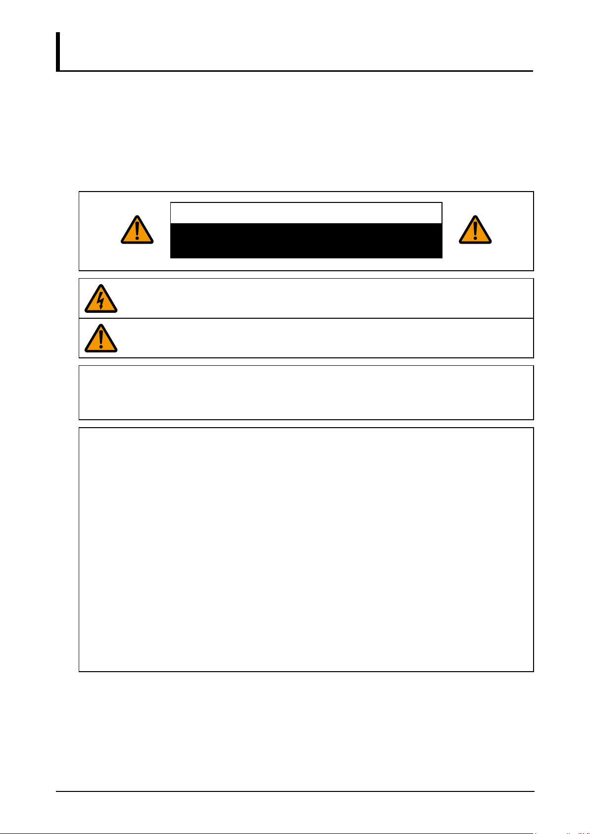
CAUTION
RISK OF ELECTRIC SHOCK
DO NOT OPEN
THIS SYMBOL INDICATES THAT DANGEROUS VOLTAGE CONSTITUTING A RISK OF
ELECTRIC SHOCK IS PRESENT WITHIN THIS UNIT.
THIS SYMBOL INDICATES THAT THERE ARE IMPORTANT OPERATING AND
MAINTENANCE INSTRUCTIONS FOR THIS UNIT IN THE USER’S MANUAL.
CAUTION
Not for use in a computer room as dened in the Standard for the Protection of Electronic Computer /
Data Processing Equipment, ANSI / NFPA 75.
Copyright notice
Please note that enlarging or reducing the size of an image for commercial purposes or public
presentation any infringe on the legally protected copyright or the copyright holder of the original
material.
About Trademarks
■ Ethernet is a registered trademark of Xerox Corporation.
■ Microsoft, Windows, Windows XP, Windows Vista, Windows 7, Windows 8 and Aero are
registered trademarks or trademarks of Microsoft Corporation in the United States and / or
other countries.
■ Mac, Mac OS and Macintosh are trademarks of Apple Inc., registered in the United States
and / or other countries.
■ HDMI, the HDMI logo and High-Denition Multimedia Interface are trademarks or registered
trademarks of HDMI Licensing, LLC.
■ PJLink is a registered trademark, or an application has been submitted for trademark, in
Japan, the United States and / or other countries or regions.
■ Crestron
Crestron Electronics, Inc.
®
, Crestron RoomView®, and Crestron Connected™ are registered trademarks of
1
Page 8

Safety Precautions
WARNING:
■ THIS APPARATUS MUST BE GROUNDED.
■ TO REDUCE THE RISK OF FIRE OR ELECTRIC SHOCK, DO NOT EXPOSE THIS APPLIANCE
TO RAIN OR MOISTURE.
■ This projector produces intense light from the projection lens. Do not stare directly into the lens,
otherwise eye damage could result. Be especially careful that children do not stare directly into the
beam.
■ Install the projector in a proper position. Otherwise it may result in a re hazard.
■ Do not cover the ventilation slots on the projector. Heat build-up can reduce the service life of your
projector, and can also be dangerous.
■ If the projector is unused for an extended time, unplug the projector from the power outlet.
■ Do not project the same image for a long time.
An afterimage may remain on the DMD panel due to the characteristics of the panel of the projector.
Caution on Hanging from the Ceiling
When hanging the projector from the ceiling, clean the air intake vents and top of the projector
periodically with a vacuum cleaner. If you leave the projector unclean for a long time, the cooling fans
can be clogged with dust, and it may cause a breakdown or a disaster.
DO NOT SET THE PROJECTOR IN GREASY, WET, OR SMOKY CONDITIONS SUCH AS IN A
KITCHEN TO PREVENT A BREAKDOWN OR A DISASTER. IF THE PROJECTOR COMES IN
CONTACT WITH OIL OR CHEMICALS, IT MAY BECOME DETERIORATED.
♦ READ AND KEEP THIS MANUAL FOR LATER USE.
All the safety and operating instructions should be read before beginning to operate the product.
Read all of the instructions given here and retain them for later use. Unplug this projector from the AC
power supply before cleaning. Do not use liquid or aerosol cleaners on the projector. Use a damp cloth
for cleaning.
Follow all warnings and instructions marked on the projector.
For added protection of the projector during a lightning storm, or when it is left unattended or unused for
long periods of time, unplug it from the wall outlet. This will prevent damage due to lightning and power
surges.
Do not expose this unit to rain or use near water. For example, in a wet basement, near a swimming
pool..., etc.
Do not use attachments not recommended by the manufacturer as they may result in hazards.
Do not place this projector on an unstable cart, stand, or table. The projector may fall, causing
serious injury to a child or adult, and serious damage to the projector. Use only with a cart or stand
recommended by the manufacturer, or sold with the projector. For wall or shelf
mounting, use a tool such as a mounting kit to secure the projector.
An appliance and cart combination should be moved with care.
Sudden stops, excessive force, and uneven surfaces may cause the appliance
and cart combination to overturn.
Slots and openings in the rear and front of the cabinet are provided for ventilation,
to insure reliable operation of the equipment and to protect it from overheating.
The openings should never be covered with cloth or other materials, and the
bottom opening should not be blocked by placing the projector on a bed, sofa, rug, or other similar
surface. This projector should never be placed near or over a radiator or heat register.
This projector should not be placed in a built-in installation such as a book case unless proper
ventilation is provided.
2
Page 9
Never push objects of any kind into this projector through cabinet slots as they may touch dangerous
voltage points or short out parts that could result in a re or electric shock. Never spill liquid of any kind
onto the projector.
Do not install the projector near the ventilation duct of air-conditioning equipment.
This projector should be operated using only the type of power source indicated on the marking label.
If you are not sure of the type of power supplied, contact the Canon Customer Support Center or local
power company.
Do not overload wall outlets and extension cords as this can result in re or electric shock. Do not allow
anything to rest on the power cord. Do not locate this projector where the cord may be damaged by
people walking on it.
Do not attempt to service this projector yourself as opening or removing covers may expose you to
dangerous voltages or other hazards. Refer all servicing to qualied service personnel.
Unplug this projector from the wall outlet and refer servicing to qualied service personnel under the
following conditions:
1. When the power cord or plug is damaged or frayed.
2. If liquid has been spilled into the projector.
3. If the projector has been exposed to rain or water.
4. If the projector does not operate normally after following the operating instructions. Adjust only
those controls that are covered in the operating instructions as improper adjustment of other
controls may result in damage and will often require extensive work by a qualied technician to
restore the projector to normal operating condition.
5. If the projector has been dropped or the cabinet has been damaged.
6. When the projector exhibits a distinct change in performance-this indicates a need for servicing.
When replacement parts are required, be sure the service technician uses replacement parts specied
by the manufacturer that have the same characteristics as the original parts. Unauthorized substitutions
may result in re, electric shock, or injury.
Upon completion of any service or repairs to this projector, ask the service technician to perform routine
safety checks to determine that the projector is in safe operating condition.
AC Power Cord Requirement
The AC Power Cord supplied with this projector meets the requirements for use in the country you
purchased it.
AC Power Cord for the United States and Canada:
The AC Power Cord used in the United States and Canada is listed by the
Underwriters Laboratories (UL) and certied by the Canadian Standard
Association (CSA).
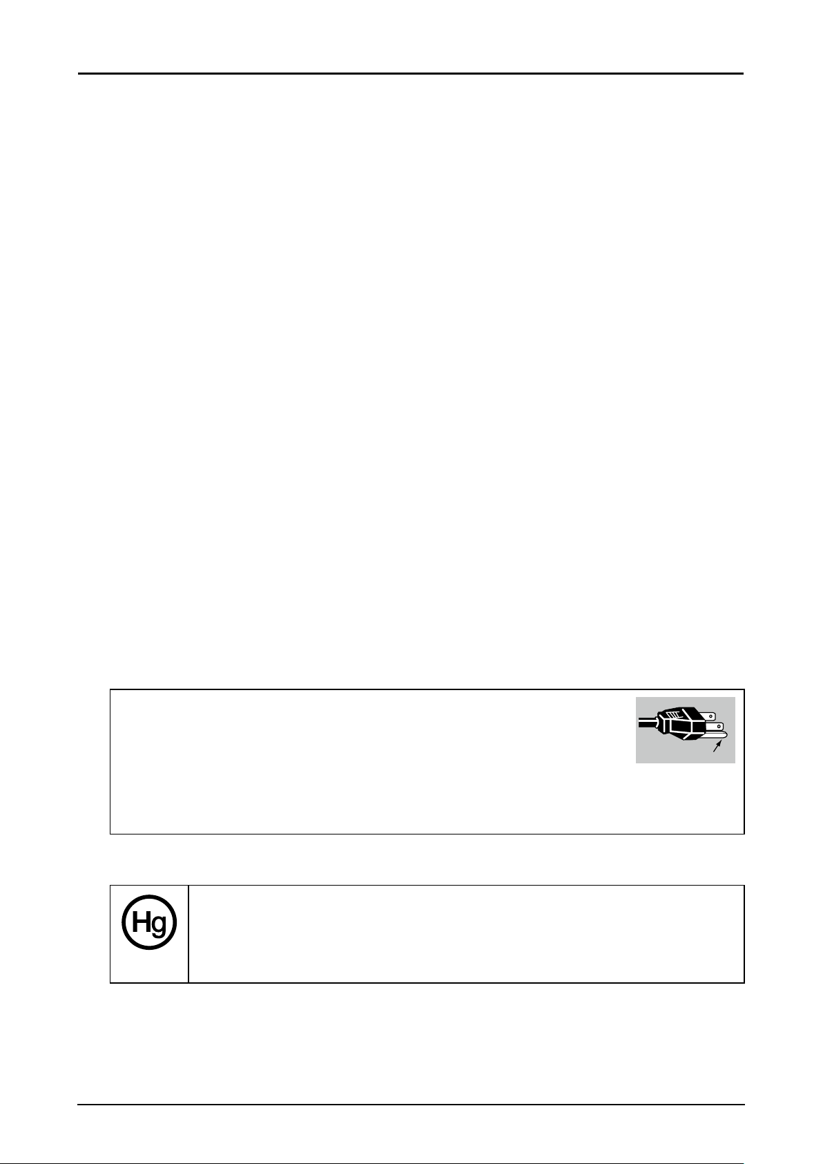
The AC Power Cord has a grounding-type AC line plug. This is a safety feature to ensure the plug ts
into the power outlet. Do not try to tamper with this safety feature. Should you be unable to insert the
plug into the outlet, contact your electrician.
THE SOCKET-OUTLET SHOULD BE INSTALLED NEAR THE EQUIPMENT AND EASILY
ACCESSIBLE.
For the U.S. and Canada, LAMP (S) INSIDE THIS PRODUCT CONTAIN MERCURY
AND MUST BE RECYCLED OR DISPOSED OF ACCORDING TO LOCAL, MUNICIPAL,
STATE, PROVINCIAL, OR FEDERAL LAWS.
For lamp recycling and disposal information please call 1-800-OK-CANON for the U.S.
and Canada.
㻳㼞㼛㼡㼚㼐
3
Page 10
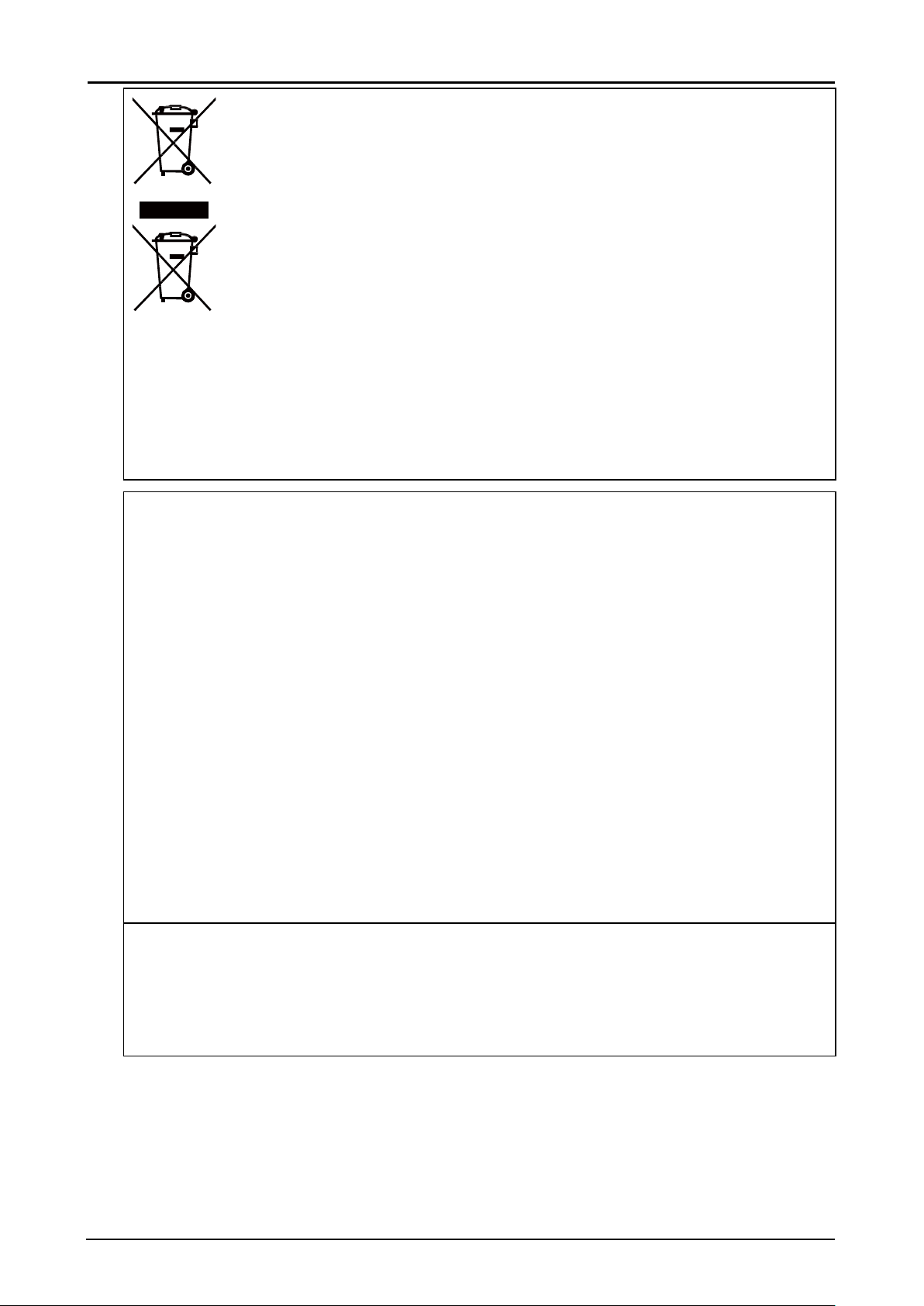
Only for European Union and EEA (Norway, Iceland and Liechtenstein)
These symbols indicate that this product is not to be disposed of with your
household waste, according to the WEEE Directive (2012/19/EU), the Battery
Directive (2006/66/EC) and/or national legislation implementing those Directives.
If a chemical symbol is printed beneath the symbol shown above, in accordance
with the Battery Directive, this indicates that a heavy metal (Hg = Mercury, Cd =
Cadmium, Pb = Lead) is present in this battery or accumulator at a concentration
above an applicable threshold specied in the Battery Directive.
This product should be handed over to a designated collection point, e.g., on
an authorized one-for-one basis when you buy a new similar product or to an
authorized collection site for recycling waste electrical and electronic equipment
(EEE) and batteries and accumulators. Improper handling of this type of waste could
have a possible impact on the environment and human health due to potentially
hazardous substances that are generally associated with EEE. Your cooperation in
the correct disposal of this product will contribute to the effective usage of natural
resources.
For more information about the recycling of this product, please contact your local city ofce, waste
authority, approved scheme or your household waste disposal service or visit
http://www.canon-europe.com/weee, or http://www.canon-europe.com/battery.
Federal Communication Commission Notice
This device complies with Part 15 of the FCC Rules. Operation is subject to the following two
conditions:
1. This device may not cause harmful interference, and
2. This device must accept any interference received, including interference that may cause
undesired operation.
Note: This equipment has been tested and found to comply with the limits for a Class A digital device,
pursuant to Part 15 of the FCC Rules.
These limits are designed to provide reasonable protection against harmful interference when the
equipment is operated in a commercial environment. This equipment generates, uses, and can
radiate radio frequency energy and, if not installed and used in accordance with the instruction
manual, may cause harmful interference to radio communications.
Operation of this equipment in a residential area is likely to cause harmful interference in which case
the user will be required to correct the interference at his own expense.
The cable with a ferrite core provided with the projector must be used with this equipment in order to
comply with Class A of the FCC Rules.
Use of a shielded cable is required to comply with Class A of FCC Rules.
Do not make any changes or modications to the equipment unless otherwise specied in the
instructions. If such changes or modications should be made, you could be required to stop
operation of the equipment.
Warning:
This is a class A product. In a domestic environment this product may cause radio interference in
which case the user may be required to take adequate measures.
The cable with a ferrite core provided with the projector must be used with this equipment in order to
comply with Class A.
Use of a shielded cable is required to comply with Class A.
4
Page 11

Safety Symbols in this Manual
This section describes the safety symbols used in this manual. Important projector safety information is
identied by the following symbols. Always observe the safety information by these symbols.
Warning
Caution
Denotes the risk of death or serious injury from improper handling if the
information is not observed. To ensure safe use, always observe this
information.
Denotes the risk of injury from improper handling if the information is not
observed. To ensure safe use, always observe this information.
5
Page 12

Precautions for Use
As this section contains important safety-related information, be sure to read the following carefully
beforehand in order to use your projector correctly and safely.
Warning
During installation, keep the projector plug easily accessible so that the projector can be unplugged
immediately if necessary, or keep a circuit breaker within reach.
If the following situations occur, turn the power off, remove the power plug from the power outlet
and contact the Canon Customer Support Center. Failure to do so could cause a re or result in an
electric shock.
■ If smoke is emitted
■ If an unusual smell or noise is emitted
■ If water or other liquid has entered the projector
■ If metal or any other foreign material has entered the projector
■ If the projector is knocked over or dropped and the cabinet is damaged
Pay attention to the following points for handling the power cord. Failure to do so may cause a re,
electric shock or personal injury.
■ Do not place any objects on the power cord and do not allow it to become trapped under the
projector.
■ Do not cover the power cord with a carpet.
■ Do not modify or excessively bend, twist, pull, wind, or bundle the power cord.
■ Keep the power cord away from heaters and other sources of heat.
■ Do not use a damaged power cord. If the power cord is damaged, purchase a replacement from
your dealer.
■ The power cord included with this projector is for use exclusively with this product. Do not use
this cord for other products.
■ Be sure to connect the ground wire of the power cord to ground.
■ Be sure to connect the ground wire before connecting the power plug to the outlet. Also when
you disconnect the ground wire, be sure to unplug the power plug from the outlet beforehand.
6
Page 13

Warning
Pay attention to the following points regarding the power source, power plug and handling of the
connector. Failure to do so may cause a re, electric shock or personal injury.
■ Do not use any power source with a voltage other than the voltage indicated (AC 100–240 V).
■ Do not pull the power cord and be sure to hold the power plug or connector when removing.
Incorrect handling may damage the power cord.
■ Do not insert any metal objects into the contact parts of the power plug or connector.
■ Do not remove the power plug or connector with wet hands.
■ Insert the power plug and connector securely up to the base. Additionally, do not use a damaged
power plug or an outlet that is loose.
■ When using an extension cord, do not exceed the cord’s rated capacity.
■ Periodically inspect the power plug and outlet and remove any dust or dirt from between the
plug and the outlet.
Installation and Handling Precautions
Pay attention to the following points regarding installation and handling of the projector. Failure to do
so may cause a re, electric shock or personal injury.
■ Do not use the projector where it might get wet, such as outdoors or by bathtubs or showers.
■ Do not place containers containing a liquid on top of the projector.
■ Do not touch the projector itself, the power cord, or the cable if lightening strikes.
■ Do not move the projector until you have switched off the power, removed the power plug from
the power outlet and unplugged any other cables.
■ Unplug the projector before cleaning or maintenance.
■ Before installing or replacing a lens unit, make sure to remove the power plug from the outlet.
Failure to do so could result in an electric shock or injury.
7
Page 14

Warning
Pay attention to the following points regarding installation and handling of the projector. Failure to do
so may cause a re, electric shock or personal injury.
■ Do not remove the cabinet from the projector or disassemble it. The interior of the projector
contains high-voltage components as well as parts that are hot. If inspection, maintenance or
repair is required, contact the Canon Customer Support Center.
■ Do not disassemble or modify the projector (including consumable parts) or the remote control.
■ Do not look directly into the exhaust vents during use.
■ Do not insert any object into vents in the projector, such as the air intake vent or exhaust vents.
■ Do not place a pressurized can in front of the exhaust vents. The pressure of the contents of the
can may increase due to heat from the exhaust vents and this could result in an explosion.
■ Using the lens shift function the lens in the projector moves up / down / left / right powered by a
motor. Do not touch the lens when the lens is moving. Doing so could cause a personal injury.
■ Before replacing the lens unit, wait at least one hour after the projector is turned off to allow the
projector to cool thoroughly. Failure to do so could result in a burn or injury.
■ When cleaning off dust or dirt from the projector lens etc., do not use any kind of spray that is
ammable. As the temperature of the lamp inside the projector is high, it could ignite, causing a
re.
■ As strong light beams are emitted while the projector is in use, do not look directly into the
projector lens. Doing so could cause an eye injury. Pay particular attention to prevent small
children from doing so.
■ When setting the projector on a high surface for projection, be sure the surface is at and stable.
■ For ceiling mounting precautions, refer to the installation manual included with the ceiling mount
(sold separately).
■ When hanging the projector from a ceiling, put the projector down on the oor or a workbench
before attaching or replacing the lens unit. Failure to do so could result in parts falling off the
projector and may cause an accident or personal injury.
8
Page 15
Warning
Precautions on the Lamp
This projector uses a high-pressure mercury lamp, which must be handled carefully and correctly as
described below.
The mercury lamp has the following characteristics.
■ The lamp will gradually become darker over time.
■ Impact, abrasion, or use of worn-out lamps may cause lamps to rupture (accompanied by a loud
noise) or burn out.
■ Lamps are more likely to rupture after the lamp replacement message is displayed (see
“Replacing the Projection Lamp” on page 58). Replace the lamp with a new one as soon as
possible.
■ Useful life of lamps varies widely from lamp to lamp and depending on the environment of use.
Some lamps may fail or rupture soon after they are rst used.
■ Be prepared by keeping a spare lamp.
Note the following precautions during lamp replacement or when a lamp has ruptured. Failure to do
so could result in an electric shock or personal injury.
■ Before replacing the lamp, always unplug the projector and wait at least an hour.
■ Ruptured lamps may scatter shards of glass inside the projector. Contact the Canon Customer
Support Center for cleaning and inspection of the projector interior and lamp replacement.
Precautions when replacing lamps that stop working
■ If illumination suddenly stops, either when you turn the projector on or after it has been on for a
while, the lamp may have ruptured. In this case, never attempt to replace the lamp by yourself.
Always request service from the Canon Customer Support Center.
■ With ceiling-mounted projectors, the lamp may fall out when you open the lamp cover, or during
replacement. During replacement, stand to the side of the lamp cover, not directly under it.
■ If the lamp ruptures, dust and gas (containing mercury vapor) may come out of the exhaust
vents. If this happens, immediately open the windows and doors to provide ventilation to the
room.
■ If you accidentally inhale gas from the lamp or get any pieces in your eyes or mouth, consult a
doctor immediately.
Warning
Precautions for the Batteries of the Remote Control
Pay attention to the following points regarding handling of batteries. Failing to do so could result in a
re or personal injury.
■ Do not heat, short circuit or disassemble the batteries, or place them in a re.
■ Do not attempt to recharge the batteries that are included with the remote control.
■ Remove the batteries when they are at or when the remote control will not be used for a long
period of time.
■ When replacing the batteries, replace both at the same time. Also, do not use two batteries of a
different type at the same time.
■ Insert the batteries with the + and - terminals in the correct directions.
■ If any liquid from inside the batteries leaks out and contacts your skin, be sure to wash the liquid
off thoroughly.
9
Page 16
Caution
Pay attention to the following points regarding installation and handling of the projector.
■ If the projector will not be used for a long period of time, be sure to remove the power plug from
the power outlet to ensure safety. Failure to do so presents a risk of re if dust accumulates on
the plug or outlet.
■ Parts of the cabinet around and above the exhaust vents may become hot during projection.
Touching these areas during operation could cause burns to the hands. Pay particular attention
in preventing young children from touching these parts. Additionally, do not place any metal
objects around or above the exhaust vents. Due to the heat from the projector, doing so could
cause an accident or personal injury.
■ Do not place the projector where it may be exposed to oily smoke or steam, such as near
kitchen counters or humidiers. Doing so may cause re or electric shock.
■ Do not place any heavy objects on top of the projector or sit / stand on it. Pay particular attention
to prevent small children from doing so. The projector may be knocked over and this could result
in damage or a personal injury.
■ Do not place the projector on an unstable or slanted surface. Doing so may cause the projector
to fall or be knocked over and could result in a personal injury.
■ Do not place any objects in front of the lens during projection. Doing so could cause a re.
■ Presenters in front of the projector should stand where the light does not seem too bright, and
where their shadow does not fall on the screen.
When handling the lamp, pay attention to the following points.
■ Be sure not to handle the lamp immediately after it has been used. Be sure to switch off the
power and wait for approximately 1 hour for the lamp and the projector to cool down sufciently.
Failure to do so could result in a burn or personal injury due to heat from the lamp or projector.
Caution for Viewing 3D Content
Pay attention to the following points when viewing 3D content.
■ Photosensitive patients, patients with heart disease, pregnant women, elderly people, and
people with serious illness and/or with a history of epilepsy should not view 3D content.
■ We advise that you should refrain from viewing 3D content if you are in bad physical condition,
need sleep or have been drinking alcohol.
■ Stop watching 3D content if you experience the following symptoms. If you experience such
symptom, immediately stop viewing 3D content and take a break until the symptom has
subsided.
■ You see doubly-blurred images or you cannot view the image stereoscopically.
■ You feel fatigue or discomfort.
■ Take breaks when viewing 3D content for an extended period of time. As this may cause eye
fatigue. Viewing 3D content for an extended period of time or viewing them from an oblique
angle can cause eye strain.
■ Parents should accompany and monitor their children as children cannot properly express
discomfort with 3D content viewing. Children who are six year of age or younger should not view
3D content.
■ The optimum 3D viewing distance from the screen is about 3 times of the vertical screen size or
more and your eyes should be level with the screen.
Caution
10
Page 17
Caution
Pay attention to the following points when carrying or transporting the projector.
■ This projector is a precision instrument. Do not knock it over or subject it to impacts. Doing so
may cause a malfunction.
■ When carrying or holding up the projector after attaching the lens unit, be sure not to hold the
lens. Doing so may cause damage to the lens unit.
■ Do not reuse any packaging or shock-absorbent materials that were supplied with the projector
at the time of purchase for transporting or shipping the projector. Protection of the projector
cannot be guaranteed if used packaging or shock-absorbent materials are reused. Fragments
from shock-absorbent material may also enter the interior of the projector which could cause a
malfunction.
■ If transportation is necessary, the lens unit should be removed before transporting the projector.
If the projector is subjected to excessive impacts during transportation, the lens unit may be
damaged. Removal and installation of the lens unit should not be performed by the user. Be
sure to have the procedure performed by a qualied technician or contact the Canon Customer
Support Center.
■ Disconnect the cables connected to the projector. Carrying the projector while the cables are
attached may cause an accident.
■ Retract the adjustable feet before moving the projector. Leaving the feet extended may cause
damage.
Caution
Pay attention to the following points when installing or using the projector.
■ Do not touch the lens with bare hands. Doing so may result in deterioration of image quality.
■ If the projector is abruptly taken from a cool to a warm location, condensation may form on the
lens or mirrors, which may cause a blurred image. Wait until the condensation has evaporated
for the image projected to return to normal.
■ Do not install the projector in a location where the temperature is high or low. Doing so may
cause a malfunction. For guidelines on operating temperatures, see “Product Specications”.
■ Do not place any objects on top of the projector that may change shape or color due to heat.
■ Projector settings must be adjusted when using the projector at high altitudes or in upward or
downward projection. Failure to adjust the settings may shorten the lamp life or damage the
lamp. For details, contact the Canon Customer Support Center.
■ Do not install the projector near high-voltage electrical power lines or an electrical power source.
■ Do not use the projector on a soft surface such as carpet or sponge mat, etc. Doing so could
cause heat to build up inside the projector and this could result in a malfunction.
■ Do not block the air intake or exhaust vents of the cooling fan. If the air intake or exhaust vent is
blocked, heat cannot be released from inside the projector, which may shorten the useful life of
the lamp or cause malfunction.
■ Installing the projector in the wrong direction may cause a malfunction or accident. Do not install
the projector with one side raised, or with the projector tilted toward the left or right.
■ Install the projector with sufcient space between air intakes and exhaust vents and walls.
Failure to do so could cause a malfunction.
■ Do not install the projector in a location that is damp, or where there is a lot of dust, oily smoke
or tobacco smoke. Doing so could cause contamination of optical components such as the lens
and the mirror and may result in deterioration of image quality.
11
Page 18
Getting Started
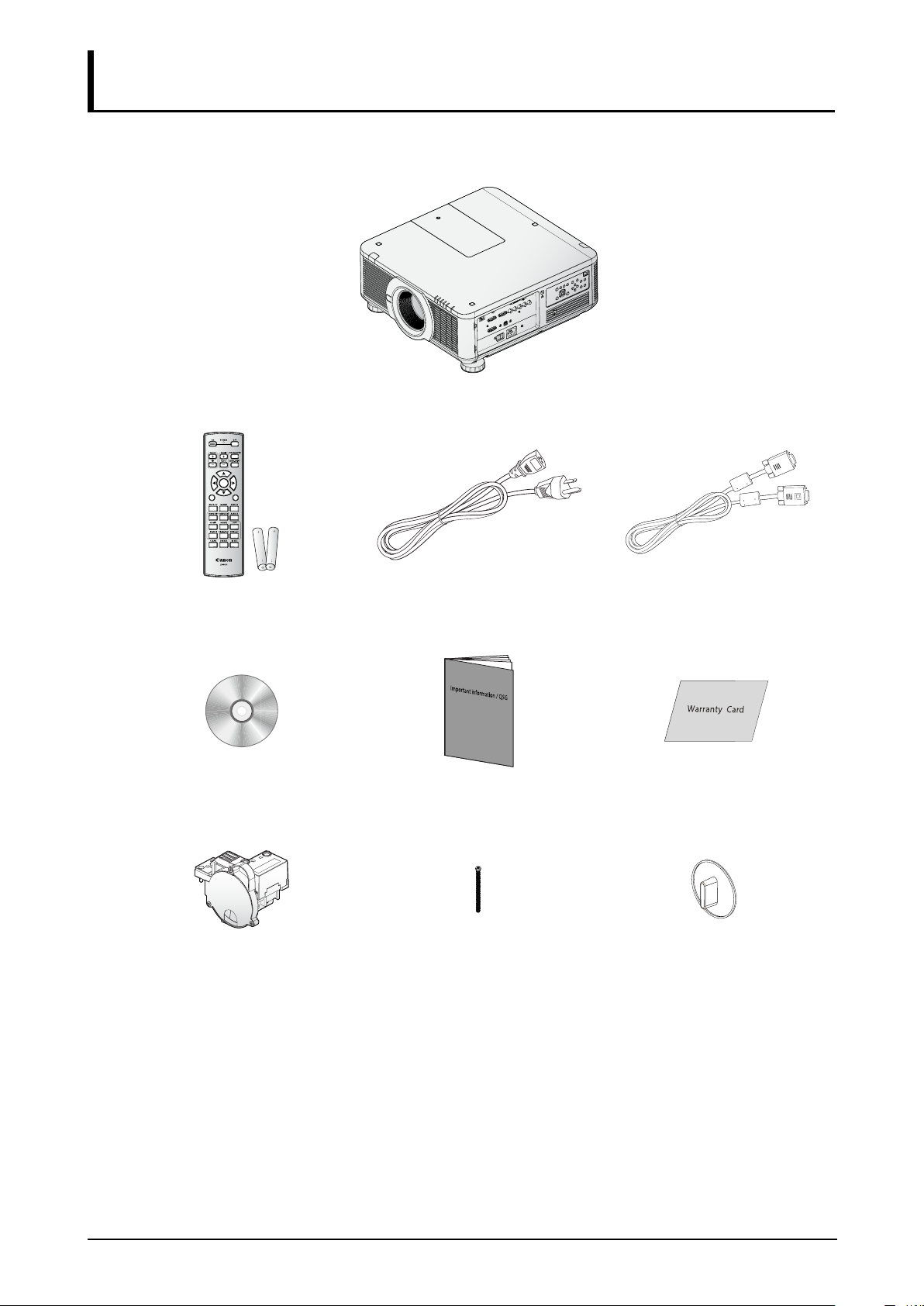
Packing Checklist
Carefully unpack the projector and check that the following items are included:
Projector
ENTER
EXIT
MENU
1
2
4
635
7089
Remote Control
Power Cord (2.5M/8.2 ft) Computer Cable (1.8M/5.9 ft)
(with two AA batteries)
CD-ROM
Important Information Warranty Card
(This User’s manual)
Color Wheel* Anti-theft Screw for Lens
Dust Cap
M4 x 0.7 x 70 mm
Contact your dealer immediately if any items are missing, appear damaged, or if the unit does not
work. It is recommend that you keep the original packing material should you ever need to return the
equipment for warranty service.
* A six-segment color wheel (6 Segment-BRT), optimized for brightness, is tted as standard. Use the
optional color wheel (6 Segment-COL) for optimized color.
12
Page 19
Views of Projector Parts
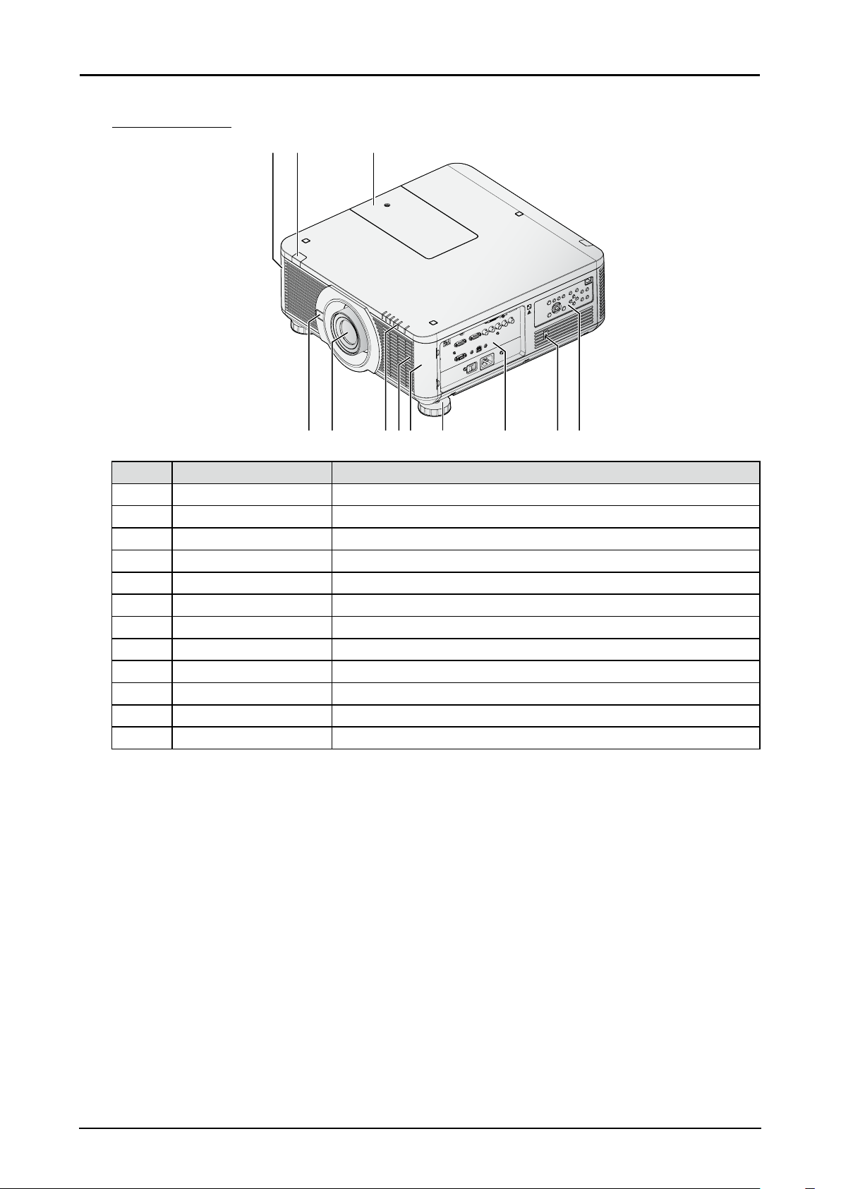
Front-right View
12
45 678
3
9
10 11 12
Item Label Description
1 Filter Cover The internal fan pulls cool air to the projector via the intake.
2 Front IR Receiver Receives IR signal from remote control.
3 Color Wheel Cover Slide to change the color wheel.
4 Lens Release Button Push to change the projector lens.
5 Lens Projection lens. (Optional)
6 LED Indicators Shows the status of the projector.
7 Filter Clean lter every 500 hours to prolong the life of the projector.
8 Filter Cover The internal fan pulls cool air to the projector via the intake.
9 Adjusting Foots Adjust the levelness the projection angle.
10 I/O Panel Use to connect to other devices.
®
11 Kensington Lock Secure to permanent object with a Kensington
Lock system.
12 Control Panel Use buttons to select or adjust the settings of the projector.
13
Page 20
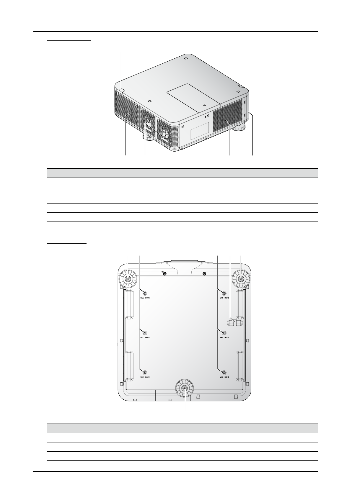
Rear-left View
1
1
23 45
Item Label Description
1 Rear IR Receiver Receives IR signal from remote control.
2 Exhaust Heat is discharged from the projector via the exhaust. Make sure
that the exhaust is clear.
3 Lamp Cover Remove to change the lamp.
4 Filter Clean lter every 500 hours to prolong the life of the projector.
5 Filter Cover The internal fan pulls cool air to the projector via the intake.
Bottom View
1 32 2
1
Item Label Description
1 Adjusting foots Adjust the levelness the projection angle.
2 Fixture screw holes Screw holes for ceiling mount.
3 Security bar Additional option to secure projector.
14
Page 21
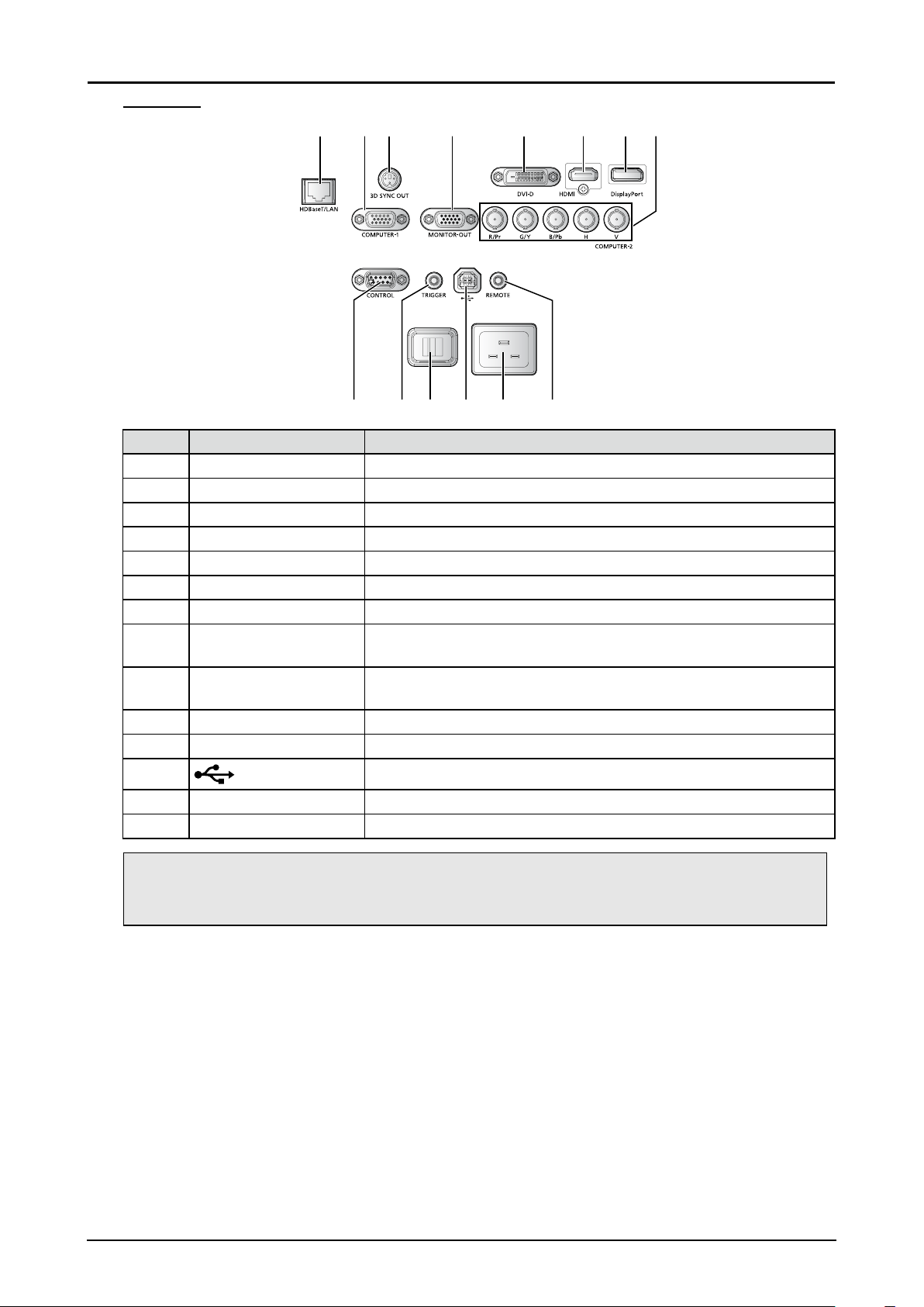
I/O Panel
13 5 6 742 8
11 13 1412109
Item Label Description
1 HDBaseT/LAN* Connect to the RJ45 cable.
2 COMPUTER-1 Connect to RGB, HD component or PC.
3 3D SYNC OUT Connect to the 3D IR synchronization signal transmitter.
4 MONITOR-OUT Connect to other display equipment for an additional display option.
5 DVI-D Connect to DVI-D devices.
6 HDMI Connect to HDMI devices.
7 DisplayPort Connect to devices that contain a DisplayPort device.
8 COMPUTER-2 Connect BNC-type input connectors to the RGB or YPbPr/YCbCr
output signal video equipment.
9 CONTROL Connect to the PC for system maintenance and projector
maintenance.
10 TRIGGER Provide 12V (+/- 1.5) output for screen operation.
11 Power Switch Turn on or off AC power of the projector.
12
Connect to an PC for maintenance.
13 Power Socket Connect the projector to a wall socket for power.
14 REMOTE Connect a 1.5 mm jack from a wired remote.
Note:
If your video equipment has various input sources, it is recommended to connect in priority of HDMI/
DVI-D, component (through VGA), Composite for better picture quality.
* Notes on HDBaseT
■ Use a shielded cable rated at CAT5e or better.
■ Maximum transmission distance is 100 m.
■ However, maximum transmission distance may be shorter in some environments.
■ Do not use the LAN cable when it is coiled or bundled.
■ Inserting or removing the LAN cable during projection may cause noise.
■ Connectivity with all HDBaseT transmitters on the market is not guaranteed.
■ Some HDBaseT transmitters may not enable correct projection when used to connect source
equipment to the projector.
15
Page 22
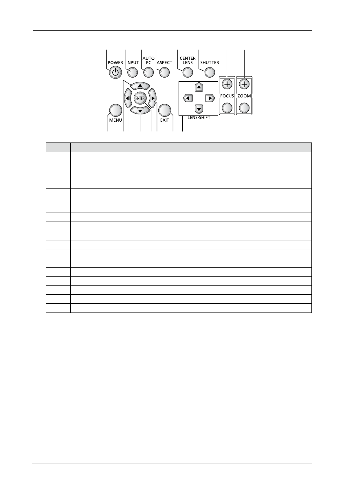
Control Panel
1
1413 1512 1691110
2 3 4 5 6 7 8
Item Label Description
1 POWER Press to turn on or off the projector.
2 INPUT Press to select the input source.
3 AUTO PC Press to initiate the automatic synchronization procedure.
4 ASPECT Press to switch to the next aspect ratio setting.
5 CENTER LENS Press to center the lens.
Note:
Please center the lens every time after the lens is installed.
6 SHUTTER Press to open or close the shutter.
7 FOCUS Press to adjust the focus of the projected image.
8 ZOOM Press to adjust the size of the projected image.
9 MENU Press to display or hide the OSD menu.
10 ▲ Navigates and changes settings in the OSD.
11 ◄ Navigates and changes settings in the OSD.
12 ▼ Navigates and changes settings in the OSD.
13 ENTER* Press to conrm the changed settings.
14 ► Navigates and changes settings in the OSD.
15 EXIT Press to return the previous level or exit the OSD menu.
16 LENS-SHIFT Press to move the lens up, down, right or left.
* Lens Adjustment Screen appears when ENTER button is pressed when OSD is not displayed.
16
Page 23
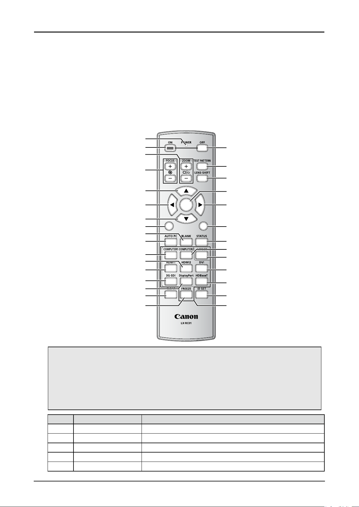
Remote Control Parts
Remote Control Precaution
■ Handle the remote control carefully.
■ Avoid excessive heat and humidity.
■ Do not short, heat, or take apart batteries.
■ Do not throw batteries into re.
■ If you will not be using the remote control for a long time, remove the batteries.
■ Ensure that you have the batteries’ polarity (+/-) aligned correctly.
■ Do not use new and old batteries together, or use different types of batteries together.
■ Dispose of used batteries according to your local regulations.
1
2
3
18
10
11
12
13
14
15
16
17
4
19
20
5
6
ENTER
21
22
7
8
MENU
EXIT
23
9
24
25
1
4
7
3
2
6
5
89
0
26
27
28
29
30
Important:
1. Avoid using the projector with bright uorescent lighting turned on. Certain high-frequency
uorescent lights can disrupt remote control operation.
2. Be sure nothing obstructs the path between the remote control and the projector.
3. The buttons and keys on the projector have the same functions as the corresponding buttons
on the remote control. This user’s manual describes the functions based on the remote control.
4. Use an exclusive Remote Control (LX-RC01).
Item Label Description
1 LED indicator Lights when the key is pressed.
2 ON Press to turn on the projector.
3 ZOOM Press to adjust the size of the projected image.
4 FOCUS Press to adjust the focus of the projected image.
5 ▲ Navigates and changes settings in the OSD.
17
Page 24

Item Label Description
6 ◄ Navigates and changes settings in the OSD.
7 ▼ Navigates and changes settings in the OSD.
8 MENU Press to display or hide the OSD menu.
9 BLANK Press to open or close the shutter.
10 AUTO PC Press to initiate the automatic synchronization procedure.
11 COMPUTER1 Press to switch input source to COMPUTER1.
12 HDMI2 Press to switch input source to HDMI.
13 HDMI1 Press to switch input source to HDMI.
14 3G-SDI No function.
15 DisplayPort Press to switch input source to DisplayPort.
16 CLEAR Reset the stored Remote ID.
17 FREEZE (*1) Press to freeze the projected image.
18 OFF Press to turn off the projector.
19 TEST PATTERN Press to display the test pattern and press again to switch to the
next test pattern. Press EXIT to return the projected image.
20 LENS-SHIFT Press to move the lens up, down, right or left.
21 ENTER (*2) Press to conrm the changed settings.
22 ► Navigates and changes settings in the OSD.
23 EXIT Press to return the previous level or exit the OSD menu.
24 STATUS Press to display the SERVICE menu (OSD).
25 COMPUTER2 Press to switch input source to COMPUTER2.
26 ASPECT Press to switch to the next aspect ratio setting.
27 DVI Press to switch input source to DVI.
28 HDBaseT Press to switch input source to HDBaseT.
29 ID SET Press to set the Remote ID.
30 Numeric buttons Press numeric to set Control ID or Remote ID.
(*1) This function is applicable to 2D signal.
(*2) Lens Adjustment Screen appears when ENTER button is pressed when OSD is not displayed.
18
Page 25
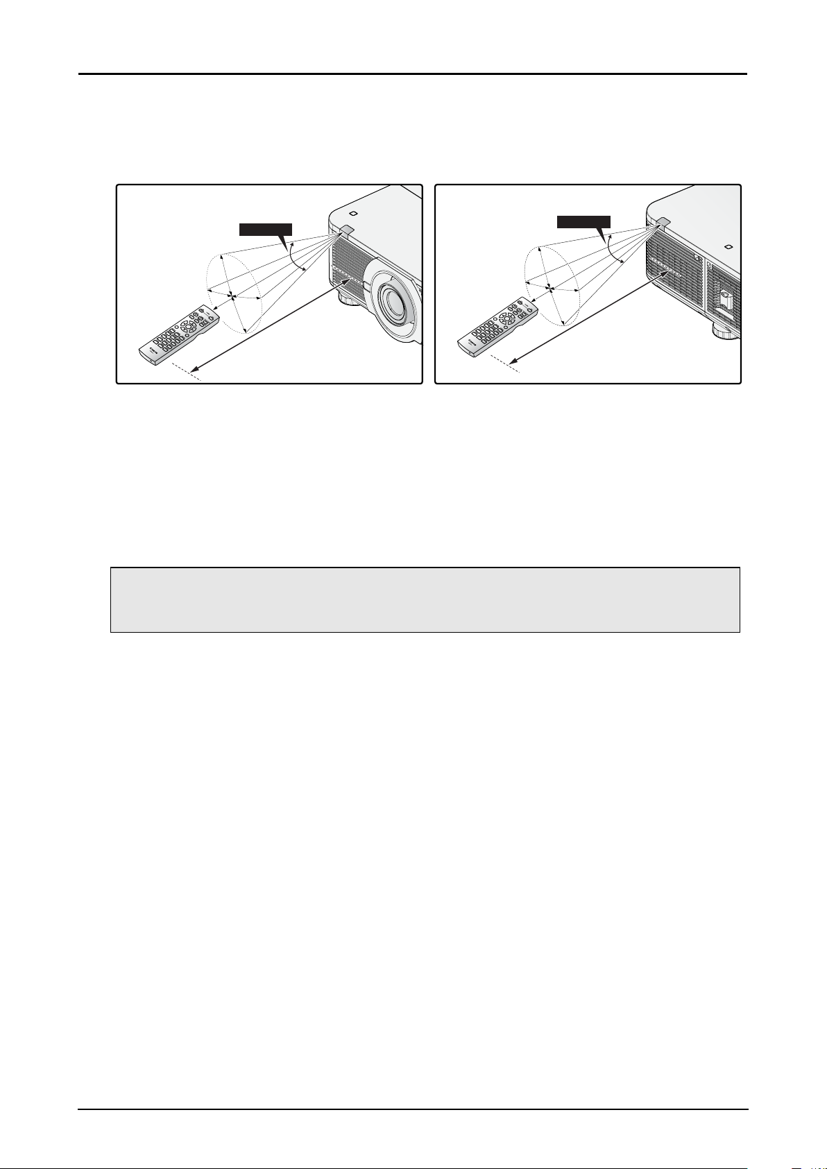
Remote Control Operating Range
The remote control uses infrared transmission to control the projector. Provided you are not holding
the remote perpendicular to the sides or the rear of the projector, the remote will function well within a
radius of about 10 meters and 30 degrees above or below the projector level. If the projector does not
respond to the remote control, move a little closer.
30 Degrees
ENT
MENU
ER
ENT
MENU
ER
1
EXI
T
4
2
7
5
3
8 9
6
0
10 m
1
EXI
T
4
2
7
5
3
8 9
6
0
30 Degrees
10 m
Setting the Remote ID to the Projector
To operate multiple projectors independently, set this ID function.
■ “Remote ID” is for a remote control.
■ “Control ID” is for a projector. See page 56.
1. Press the ID SET button for three seconds. The LED indicator on the remote control blinks.
2. To designate the Remote ID, press and hold the 2 digit number (01 ~ 99) each button for 1 second
at least. The remote control backlight blinks. Once initiated, the ID set procedure allows for ten
seconds to complete the process. After ten seconds, you must restart the procedure.
Note:
The factory default is “X / X”. “X” means all ID. And the left side is “Control ID”. The right side is
“Remote ID”. See page 56.
Clearing the Remote ID
Press the ID SET and CLEAR for ve seconds. The remote control backlight blinks signifying that the
ID setting is cleared.
Projector and Remote Control Buttons
The projector can be operated using the remote control or the buttons on the side of the projector. All
operations can be carried out with the remote control; however, the buttons on the projector are limited
in use.
19
Page 26
Setup and Operation
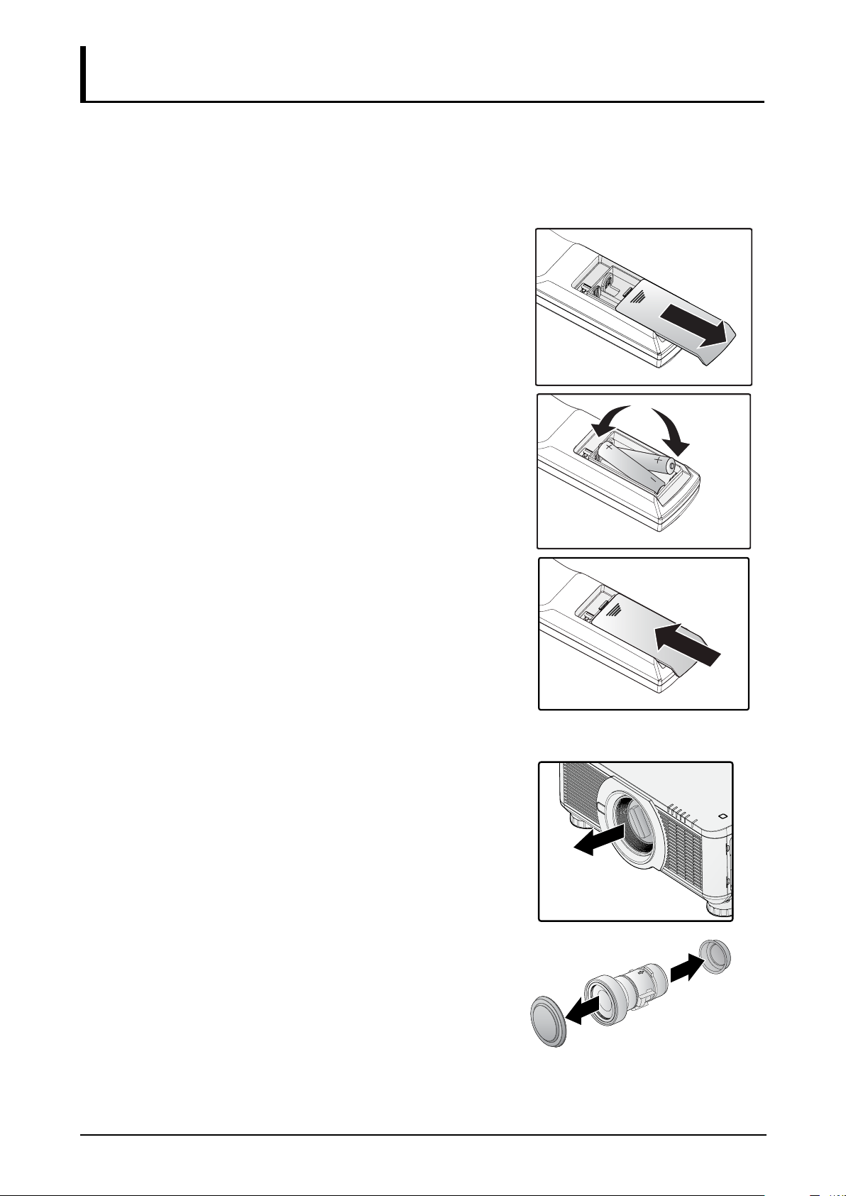
Inserting the Remote Control Batteries
■ Make sure the battery is installed with the correct polarity.
■ Do not use the old and new batteries or the batteries of different types together.
■ Remove the battery if the remote control may not be used for a long time to prevent the damage
caused by leaks.
1. Slide the battery cover as illustrated.
2. Place two AA batteries in the compartment, make sure
the polarity in the compartment and batteries are aligned
correctly.
3. Slide the battery cover back.
Installing the Lens
1. Remove the dust cap.
2. Remove the new lens from its packaging.
3. Remove the lens covers from the rear and front of the
new lens. Remove them before continuing.
20
Page 27
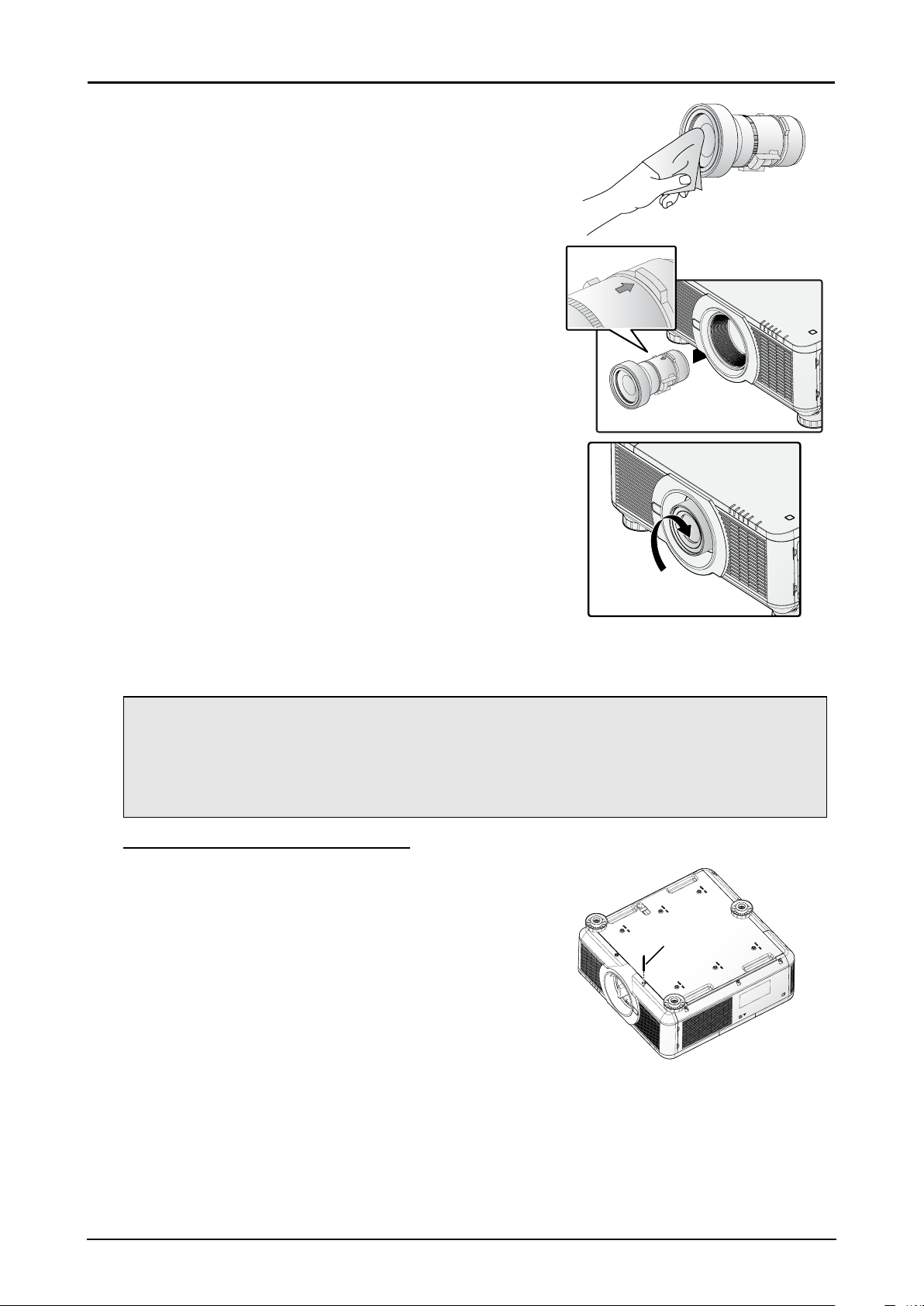
4. Clean the new lens before installing. Take care when
cleaning to prevent scratching the surface of the new
lens.
5. Make sure the connector is facing up and new lens is
pushed into the holder.
6. Turn the new lens clockwise until and audible Click is
heard signifying the new lens is secured and seated
correctly.
7. Gently pull on the new lens to ensure it is locked in
place. If the new lens does not come off, it is seated
correctly.
Note:
■ The projector supports the lens memory function. Perform the memory function every time
when you install the lens.
■ Be sure to execute “Center Lens” after the lens is changed.
■ Refer to User’s Manual attached to optional lens as well.
Using the Anti-theft Screw for Lens
To prevent the accidental removal of the lens, fasten the Antitheft screw for lens included with the projector to the bottom
of the projector.
Anti-theft
screw for
lens
21
Page 28

Precaution for Installing the Projector
The high quality display from the project is only available when the projector is correctly installed.
Generally, the light source facing the screen should be reduced or eliminated as much as possible. The
contrast of the image will be obviously reduced if the light directly shines on the screen, such as the
beam from windows or the searchlight cast on the image. The image may become faded and not bright.
Projector Installation and Setup
There are six xture screw holes (M4 x 0.7 x 12mm) at the bottom of projector for ceiling mounting. The
available installation options are available as follows:
■ Front Table: Install the projector on the table and project the image forward.
■ Rear Table: Install the image behind the screen and project onto the screen.
■ Front Ceiling: Mounting the projector on the ceiling and project the image forward.
■ Rear Ceiling: Mounting the projector on the ceiling behind the screen and project onto the screen.
■ Up + Front: Projector is mounted vertically upwards and the image is projected onto the ceiling
mounted screen.
■ Down + Front: Projector is mounted vertically downwards the image is projected onto the oor
mounted screen.
Cautions for Ventilation
The product is a high-brightness projector. The intake with lters are located on the left and right sides
to provide sufcient air for cooling. The projector has two vents on the back for cool air discharging.
When installing, make sure the intake and outlet vents meet the required clearance to allow for the
proper cooling requirements of the system. At least 50cm around the intake and 70cm around the vent
should be clear.
Make sure that there is no obstruction or ammable material in proximity of the vents when the projector
is installed so that necessary cooling is applied to the system.
50cm
Or Greater
PRESS
Release
Lens
50cm
Or Greater
70cm
Or Greater
Note:
■ Inadequate cooling may cause the projector to stop operations due to overheating.
■ Overheating may shorten the life of components or lamps.
■ If installation requirements necessitate installation in a structure or enclosed space, the intake
and outtake vents should not be obstructed to prevent overheating.
22
Page 29

Connecting the Projector
Connecting to the PC
Desktop or NotebookMonitor
Connecting to the Video Devices
DVD Player
23
Page 30

Connecting to the Control Devices
3D Sync
Transmitter
OFF
POWER
ATTERN
N
P
O
EST
T
M
T
HIF
S
S
LEN
S ZOO
CU
O
F
ENTER
T
EXI
US
T
STA
MENU
BLANK
ECT
TO SYNC
3
AU
COMPUTER2ASP
R1
E
2
T
U
6
COMP
HDMI2HDMI1 DVI
eT
s
1
5
t3G-SDI HDBa
r
9
ay Po
4
ET
Displ
S
8
E ID
EEZ
R
F
7
0
LEAR
C
IES
00 SER
7
LX-MU
Desktop or Notebook
Connecting to the Screen Trigger
Remote Countrol
Projector Screen
24
Page 31

Connecting to the External HDBaseT Transmitter
Desktop or Notebook
Control PC
Control PC
DVD Player
YPbPrVGA IN HDMI
Hub
LAN
HDBaseT transmitter
RS-232
RJ45RJ45
Starting and Shutting down the Projector
1. Connect the power cord to the projector. Connect the
other end to a wall outlet.
2. Turn on the power switch.
3. Make sure the POWER LED displays solid red.
Press the POWER button on the projector or the ON
button on the remote control to turn on the projector.
See “Power LED Indicator” on page 73.
POWER STATUS LAMP1 LAMP2 TEMP. SHUTTER
25
Page 32

4. Press the source buttons on the remote control or
INPUT on the projector to select a desired input source.
5. Press the POWER button on the projector or the OFF
button on the remote control to show the “Power Off? /
Press Power again” prompt.
6. Press the POWER button on the projector or the OFF
button on the remote control to turn off the projector.
The cooling fan continues to rotate for a while after
Power Switch is turned off or the power cable is
unplugged.
Note:
■ Use the projector’s supplied power cord.
■ Conrm the projector’s power requirements before installing to make sure the power supply
meets the projector’s specication requirements.
Caution:
Do not unplug the power cord and do not turn off the power switch until the POWER LED solid red indicating the projector has cooled down.
Adjusting the Projector Level
Take note of the following when setting up the projector:
■ The projector table or stand should be level and sturdy.
■ Position the projector so that it is perpendicular to the screen.
■ Ensure the cables are secured and out of the way to avoid tripping on them and prevent damage or
injury.
To level the projector on the installation surface, turn the tilt-adjuster right or left until the desired angle
is achieved.
26
Page 33

Adjusting the Focus and Zoom
1. Press FOCUS +/- on the projector or the remote control to sharpen the projected image.
2. Press ZOOM +/- on the projector or the remote control to adjust the size of the image (ZOOM +
increases image size, ZOOM - decreases image size).
ENTER
MENU
EXIT
1
2
4
635
7089
Adjust the Keystone
1. Press MENU. Press ◄ or ► to navigate to ALIGNMENT.
2. Press ▲ or ▼ until Keystone is selected.
3. Press ENTER to enter keystone control menu.
4. Press ◄ or ► to correct keystone distortion.
When the aspect is set to real in low-resolution mode, OSD may become out of range depending on the
level of Keystone adjustment.
Adjusting the Lens Shift
The projector has the lens shift feature and the image can be vertically adjusted without moving the
projector.
27
Page 34

Vertical Lens Shift
V
The lens on a desk mounted projector can move down to up from 0% to 50% (0.5V).
Image
Max. 0.5V
V
Max. 0.5
Image
Vertical Shift
Lens Center
The lens of the ceiling mounted projector can move up to down from 0% to 50% (0.5V).
Lens Center
V
Max. 0.5V
Vertical Shift
Image
Max. 0.5V
Image
■ The above lens shift range is for LX-IL01UW (ultra wide zoom lens), LX-IL02WZ (wide zoom lens),
LX-IL03ST (standard zoom lens), LX-IL04MZ (middle zoom lens), LX-IL05LZ (long zoom lens),
LX-IL06UL (ultra long zoom lens), except LX-IL07WF (short xed lens).
■ Optical performance guaranteed range for lens shift varies according to the lens to be mounted.
■ The LX-IL07WF (short xed lens), optical performance guaranteed range is limited at 0% position.
28
Page 35

Horizontal Lens Shift
M
M
The image can be shifted horizontally to the right or left by 10% (0.1H) without moving the projector.
ax. 0.5V
V
Image
0.1H
Lens Center
H
■ The above lens shift range is for LX-IL02WZ (wide zoom lens), LX-IL03ST (standard zoom lens),
LX-IL04MZ (middle zoom lens), LX-IL05LZ (long zoom lens), LX-IL06UL (ultra long zoom lens).
■ Optical performance guaranteed range for lens shift varies according to the lens to be mounted.
■ The LX-IL07WF (short xed lens), optical performance guaranteed range is limited at 0% position.
0.1H
Horizontal Lens Shift for LX-IL01UW (Ultra Wide Zoom Lens)
The image can be shifted horizontally to the right or left by 6.70% (0.067H) without moving the projector.
ax. 0.5V
V
Image
Lens Center
■ The above lens shift range is for LX-IL01UW (ultra wide zoom lens).
■ Optical performance guaranteed range for lens shift varies according to the lens to be mounted.
0.067H
H
0.067H
29
Page 36

On-Screen Display (OSD) Menu Settings
OSD Menu Controls
The projector has an OSD that lets you make image adjustments and change various settings.
Navigating the OSD
You can use ▲, ▼, ◄ or ► on the remote control or the projector keypad to navigate and adjust
settings.
ENTER
MENU
1
4
7089
EXIT
3
2
6
5
1. Press MENU to enter the OSD.
2. There are six menus. Press ◄ or ► to move through the menus.
3. Press ▲ or ▼ to move up and down in a menu.
4. Press ◄ or ► to change values for settings.
5. Press MENU to close the OSD or return the previous menu.
30
Page 37

Setting the OSD Language
Set the OSD language (default: English) to your preference before continuing.
1. Press MENU. Press ◄ or ► to navigate to CONTROL.
2. Press ▲ or ▼ until Language is selected.
3. Press ▲ or ▼ until the language you want is selected.
4. Press MENU three times to close the OSD.
31
Page 38

OSD Menu Overview
Main Menu Sub Menu Setting
DISPLAY Input Selection HDMI / DVI-D / Computer-1 / Computer-2/BNC / DisplayPort /
HDBaseT
Test Pattern Color Bar / Crosshatch / Burst / Red / Green / Blue / White
/ Black / H Ramp / Uncorrected Red / Uncorrected Green /
Uncorrected Blue / Uncorrected White / Uncorrected Black / Off
Color Space Auto / YCbCr / YPbPr / RGB-PC / RGB-Video
Input Lock Auto / 48Hz / 50Hz / 60Hz
Background Logo / Blue / Black / White
Auto PC Adjust Auto / Always
Auto PC Enter
Blue Only On / Off
PICTURE Picture Mode Presentation / Standard / Video
Contrast 0 ~ 200
Brightness 0 ~ 200
Saturation 0 ~ 200
Hue 0 ~ 200
Gamma Film / Graphics / Video / Linear / PC
Color Color Temperature Native / 5400K / 6500K / 9300K
White Balance Red Offset / Green Offset / Blue Offset /
Red Gain / Green Gain / Blue Gain
Hue Red / Green / Blue / Cyan / Magenta /
Yellow
Saturation Red / Green / Blue / Cyan / Magenta /
Yellow
Gain Red / Green / Blue / Cyan / Magenta /
Yellow
White Gain Red / Green / Blue
Sharpness 0 ~ 31
Noise Reduction 0 ~ 15
Aspect Ratio 5:4 / 4:3 / 16:10 / 16:9 / 1.88 / 2.35 / Letterbox / Auto / True Size
Overscan Off / Crop / Zoom
VGA Setup H Total / H Start / H Phase / V Start
LAMPS Mode Dual / Lamp 1 / Lamp 2 / Single
Power Normal / Eco / Custom Power Level
High Altitude On / Off
Custom Power Level 75% ~ 100% (32 steps)
Lamp Warning
Display
Lamp 1 Status On / Off
Lamp 2 Status On / Off
Factory Settings (after reset) are in bold letters.
On / Off
32
Page 39

Main Menu Sub Menu Setting
ALIGNMENT Projection Mode Front Table / Rear Table / Front Ceiling / Rear Ceiling / Up +
Front / Down + Front
Lens Control Enter to Zoom/Focus
Lens Memory Load Memory Memory 1, 2, 3, 4, 5, 6, 7, 8, 9, 10
Edit Memory Memory 1, 2, 3, 4, 5, 6, 7, 8, 9, 10
Center Lens Enter
Keystone -80 ~ +80
Digital Alignment Digital Zoom / Digital Pan / Digital Scan / Reset
H/V Alignment H Zoom / V Zoom / H Shift / V Shift / Reset
CONTROL Standby Mode Standard / ECO / Network
Auto Power Off On / Off
Direct Power On On / Off
Network IP Address 192.168.0.100
Subnet mask 255.255.255.0
Gateway 192.168.0.254
DHCP On / Off
Apply OK / Cancel
RS232 Baud rate 115200 / 57600 / 38400 / 19200 / 14400 /
9600 / 4800 / 2400
Channel Local / HDBaseT
Startup Logo On / Off
Trigger On / Off
Auto Search On / Off
Dynamic Black On / Off
3D 3D Format Off / Auto / Side by Side / Top and
Bottom / Frame Sequential
DLP Link Off / On
3D Swap Normal / Reverse
3D 24Hz Display 96Hz / 144Hz
Language English
/ Italiano / русский / 简体中文 / 繁體中文 / 한국어 / 日本語
Control ID Control ID Enable Off / On
Control ID Number 1 ~ 99
Remote ID Number 1 ~ 99
Factory Settings (after reset) are in bold letters.
/ Français / Español / Deutsch / Português / Nederlands
33
Page 40

Main Menu Sub Menu Setting
SERVICE Model LX-MU700
Serial Number XXXXXXXXXXXX
Software Version 1 MP05-SE06-RD01-9B07
Software Version 2 0D06-LD11-PD06-3090
Control / Remote ID X / X
Active Source Computer-1
Pixel Clock 148.50 MHZ
Signal Format 1920 x 1080P
H/V Refresh Rate H: 67.5 KHZ V: 60 HZ
Lamp 1 / 2 Time xxxx / xxxx HRS
Power On Time xxxx HRS
Factory Reset Reset Everything ? OK / Cancel
Factory Settings (after reset) are in bold letters.
34
Page 41

DISPLAY Menu
Label Description
Input Selection Press ENTER to enter the Input Selection menu.
Test Pattern Press ENTER to display different test patterns for projector installation
check. Press EXIT to close test pattern.
Color Space Press ◄ or ► to adjust the color space. The options are Auto, YCbCr,
YPbPr, RGB-PC and RGB-Video.
Input Lock Press ◄ or ► to lock the input source to internal sync signal. The options
are Auto, 48Hz, 50Hz and 60Hz.
Background Press ◄ or ► to specify the image to be background when no signal. The
options are Logo, Blue, Black and White.
Auto PC Adjust Press ◄ or ► to set auto synchronization for the input signal. The options
are Auto and Always.
Auto PC Press ENTER to execute the auto sync input signal.
Blue Only Turns Blue Only mode On/Off. Used for maintenance.
35
Page 42

PICTURE Menu
Label Description
Picture Mode (*1) Press ◄ or ► to select a picture mode. The options are Presentation,
Standard and Video
Contrast Press ◄ or ► to adjust the contrast of the projected image.
Brightness Press ◄ or ► to adjust the brightness of the projected image.
Saturation (*2) Press ◄ or ► to adjust the saturation level of the color.
Hue (*2) Press ◄ or ► to adjust the level of hue for reproduction of the true color.
Gamma Press ◄ or ► to adjust the gamma correction of the projected image. The
options are Film, Graphics, Video, Linear and PC.
Color Press ENTER to enter the Color menu. See “Color Menu” on page 37.
Sharpness Press ◄ or ► to adjust the sharpness.
Noise Reduction Press ◄ or ► to adjust the noise of the projected image.
(*1) Picture Mode is set as the standard for 3D projection.
(*2) Adjustment is possible only when video signal is input.
36
Page 43

Label Description
Aspect Ratio Press ◄ or ► to adjust the aspect of the projected image.
Aspect ratio for 16:10:
Native input
16:10
Output aspect ratio
5:4
Output aspect ratio
4:3
Output aspect ratio
16:9
Output aspect ratio
1.88
Output aspect ratio
2.35
Output aspect ratio
Letterbox
Output aspect ratio
Auto
Output aspect ratio
True Size
Aspect ratio for 4:3:
Native input
4:3
Output aspect ratio
5:4
Output aspect ratio
2.35
Output aspect ratio
4:3
Output aspect ratio
Letterbox
Output aspect ratio
16:9
Output aspect ratio
Auto
Output aspect ratio
1.88
Output aspect ratio
True Size
Overscan Press ◄ or ► to hide edge of the projected image to damage the noise
appear. The options are Off, Crop and Zoom.
VGA Setup* Press ENTER to enter the VGA Setup menu. See “VGA Setup Menu” on
page 38.
* Adjustment is possible only when signals from the computer is input through Computer-1 and
Computer-2/BNC.
Color Menu
Label Description
Color Temperature Press ◄ or ► to adjust the color temperature. The options are Native,
5400K, 6500K and 9300K.
White Balance Press ENTER to enter the White Balance menu. Press ▲, ▼, ◄ or ► to
adjust settings.
37
Page 44

Label Description
Hue Press ENTER to enter the Hue menu. Press ▲, ▼, ◄ or ► to adjust
settings.
Saturation Press ENTER to enter the Saturation menu. Press ▲, ▼, ◄ or ► to adjust
settings.
Gain Press ENTER to enter the Gain menu. Press ▲, ▼, ◄ or ► to adjust
settings.
White Gain Press ENTER to enter the White Gain menu. Press ▲, ▼, ◄ or ► to adjust
settings.
VGA Setup Menu
Label Description
H Total Press ◄ or ► to adjust H Total for the Computer-1 / Computer-2/BNC signal
display.
H Start Press ◄ or ► to adjust H Start for the Computer-1 / Computer-2/BNC signal
display.
H Phase Press ◄ or ► to adjust H Phase for the Computer-1 / Computer-2/BNC
signal display.
V Start Press ◄ or ► to adjust V Start for the Computer-1 / Computer-2/BNC signal
display.
38
Page 45

LAMPS Menu
Label Description
Mode Press ENTER to enter the Mode menu. Press ▲ or ▼ to select lamp mode.
The options are Dual, Lamp 1, Lamp 2 and Single.
Note:
1. In Lamp 1/2 mode, the projector switches between lamps when a lamp
error is detected. The corresponding lamp LED ashes.
2. A system reboot is recommended after setting the lamp mode to
Single mode. In Single mode, the projector choose shorter one of the
lamp usage time at start up, and use it while the Lamp is ON.
3. Lamp life may be shortened if the user quickly switches between
lamp mode. Lamp mode function is disabled between switch mode
operations until the operation is completed.
4. The lamp mode options are not available before lamp mode switching
is complete. It takes about 5 minutes.
Power Press ◄ or ► to select a power mode. The options are Normal, Eco and
Custom Power Level.
High Altitude This setting is required under the following conditions.
Temperature Sea Level
5°C ≤ , ≤ 23°C 1200 m ~ 3000 m
23°C < , ≤ 40°C 1219 m ~ 3048 m
Press ◄ or ► to enable or disable the cooling fan of the projector.
Note:
If the projector is in operation in a high heat or high altitude environment,
it may shut down automatically. In this setup, you can enable the High
Altitude function by selecting On and setting the fan to operate at a higher
speed to maintain proper cooling levels on the projector.
Custom Power Level Press ◄ or ► to adjust custom power level. The function is only available
when Power is Custom Power Level.
39
Page 46

Label Description
Lamp Warning Display Press ◄ or ► to enable or disable the warning message.
Specify whether to show a lamp replacement message after the lamp has
been used for a specied period.
■ Setting display to Off will disable both the message to prepare a
replacement lamp and the warning to replace the lamp. To review the
replacement timing, check the lamp counter.
■ Lamps that are still used after the timing for lamp replacement are
more likely to rupture. Replace the lamp with a new one as soon as
possible.
Lamp 1 Status Shows the current status of Lamp 1.
Lamp 2 Status Shows the current status of Lamp 2.
ALIGNMENT Menu
Label Description
Projection Mode Press ◄ or ► to select a projection mode. The options are Front Table,
Rear Table, Front Ceiling, Rear Ceiling, Up + Front and Down + Front.
Lens Control Press ENTER to enter the Lens Control menu. See “Lens Control Menu”
on page 41.
Lens Memory Press ENTER to enter the Lens Memory menu. See “Lens Memory Menu”
on page 41.
Center Lens Press ENTER to set the lens to the default center position.
Note:
Calibrate the lens whenever a lens is mounted on the projector.
Keystone Press ◄ or ► to adjust vertical distortion brought by the projection angle.
Digital Alignment* Press ENTER to enter the Digital Alignment menu. See “Digital Alignment
Menu” on page 43.
40
Page 47

Label Description
H/V Alignment Press ENTER to enter the H/V Alignment menu. See “H/V Alignment Menu”
on page 43.
* This function is grayed-out and unusable when in 3D projection. Additionally, settings made in 2D
projection will be reset (turned to 0) when 3D projection is turned on.
Lens Control Menu
Switch between Lens Shift, Zoom/Focus menus by pressing ENTER button.
Label Description
Zoom Press ▲ or ▼ to adjust zooming of the lens.
Focus Press ◄ or ► to adjust focusing of the lens.
Shift V Press ▲ or ▼ to adjust horizontal shift of the lens.
Shift H Press ◄ or ► to adjust vertical shift of the lens.
Lens Memory Menu
Label Description
Load Memory Press ENTER to enter the lens memory list. Press ▲ or ▼ to select and
press ENTER to execute the lens setting.
Edit Memory Press ENTER to enter the lens memory list. See “Edit Memory” on page
42.
41
Page 48

Note:
The projector can save information about the lens position in memory. Up to ten sets of lens
information (including focus, zoom, and lens shift settings) can be saved, and the lens can be
restored to these positions.
■ When saved lens positions are restored, images may be projected in a slightly different
position than the saved position.
■ Specifying a somewhat smaller image size than the screen size (image area) enables you to
switch among multiple lens positions without having the image extend off the screen.
■ When precise positioning is needed, use lens shift, zoom, and focus functions for ne
adjustment.
Edit Memory
Label Description
Memory 1 - 10 Press ▲ or ▼ to select, press ENTER to saving settings and press ► to
open the Edit Memory window and keyboard. Press ▲, ▼, ◄ or ► and
ENTER to select or conrm the setting.
Note:
A maximum number of nine letters, numbers, symbols and spaces are
allowed.
42
Page 49

Digital Alignment Menu
Label Description
Digital Zoom Press ◄ or ► to enlarge the projected image.
Digital Pan Press ◄ or ► to move the projected image horizontally. The function is only
available when the image is enlarged.
Digital Scan Press ◄ or ► to move the projected image vertically. The function is only
available when the image is enlarged.
Reset Press ENTER to set to the default value.
Note:
This function is grayed-out and unusable when in 3D projection. Additionally, settings made in 2D
projection will be reset (turned to 0) when 3D projection is turned on.
H/V Alignment Menu
Label Description
H Zoom Press ◄ or ► to narrow the horizontal size of the projected image.
V Zoom Press ◄ or ► to narrow the vertical size of the projected image.
43
Page 50

Label Description
H Shift Press ◄ or ► to move the narrowed projected image horizontally. The
function is only available when the image is narrowed.
V Shift Press ◄ or ► to move the narrowed projected image vertically. The function
is only available when the image is narrowed.
Reset Press ENTER to set to the default value.
CONTROL Menu
Label Description
Standby Mode Press ◄ or ► to select a standby mode. The options are Standard, ECO
and Network. Refer to the “Note” on page 50 for details.
Auto Power Off Press ◄ or ► to enable or disable turning off the projector when no input
signal is received within 15 minutes.
Direct Power On Press ◄ or ► to enable or disable turning on the projector when connect to
an AC power.
Network Press ENTER to enter the Network menu. See “Network Menu” on page
45.
RS232 Press ENTER to enter the RS232 menu. See “RS232 Menu” on page 50.
Startup Logo Press ◄ or ► to enable or disable the Startup Logo.
Trigger Press ◄ or ► to enable or disable turning on the screen when the projector
is powered on.
Auto Search Press ◄ or ► to enable or disable auto search function.
Dynamic Black* Press ◄ or ► to enable or disable dynamic black function
3D Press ENTER to enter the 3D menu. See “3D Menu” on page 54.
Note:
Before adjusting the 3D setting, ensure the input signal is connected.
* Optimizes the contrast depending on the brightness of each scene by adjusting lamp output
automatically based on the brightness data from the input source.
44
Page 51

Label Description
Language Press ENTER to enter the Language menu. Press ▲ or ▼ to select the
language of OSD menu. The options are English, Français, Español,
Deutsch, Português, Nederlands, Italiano, русский
한국어 and 日本語 .
Control ID Press ENTER to enter the Control ID menu. See “Control ID Menu” on
page 56.
,
简体中文 , 繁體中文,
Network Menu
Label Description
IP Address Press ENTER to open the IP Address window. Press ◄ or ► to select
the number in the address and press ▲ or ▼to increase or decrease the
selected number.
Subnet mask Use it to set the subnet mask. The input method is same as the IP address.
Gateway Use it to set the gateway. The input method is same as the IP address.
DHCP Press ◄ or ► to enable or disable DHCP setting.
Apply Press ENTER to execute. The settings will be saved after applied.
45
Page 52

For simplicity and ease of operation, the projector provides diverse networking and remote management
features.
The LAN/RJ45 function of the projector through a network, such as remotely manage: Power On/Off,
Brightness and Contrast settings. Also, projector status information, such as: Video-Source, etc.
(Ethernet)
The projector can be controlled by a PC (Laptop) or other external device with connecting to the
projector’s LAN/RJ45 port.
Wired LAN Terminal Functionalies
Remote control and monitoring of a projector from a PC (or Laptop) via wired LAN is also possible.
Compatibility with Crestron / AMX (Device Discovery) / Extron control boxes enables not only collective
projector management on a network but also management from a control panel on a PC (or Laptop)
browser screen.
■ Crestron is a registered trademark of Crestron Electronics, Inc. of the United States.
■ Extron is a registered trademark of Extron Electronics, Inc. of the United States.
■ AMX is a registered trademark of AMX LLC of the United States.
Note:
There is a limitation of power on/off control sequence in Network mode. It must take around 8~9 sec
after executing the power on command, regardless over the keypad, remote or IP.
Supported External Devices
This projector is supported by the specied commands of the Crestron Electronics controller and related
software (ex, RoomView®).
http://www.crestron.com/
This projector is supported by AMX (Device Discovery).
http://www.amx.com/
This projector is compliant to support Extron device(s) for reference.
http://www.extron.com/
46
Page 53

LAN RJ45
1. Connect an RJ45 cable to the RJ45 port on the projector and the PC (Laptop).
LAN
Compatible browsers are as follows.
Microsoft Internet Explorer 9 with Adobe Flash Player 9.0 or higher.
2. On the PC (Laptop), select Start → Control Panel → Network and Internet.
47
Page 54

3. Right-click on Local Area Connection, and select Properties.
4. In the Properties window, select the Networking tab, and select Internet Protocol (TCP/IP).
5. Click Properties.
6. Click Use the following IP address and ll in the IP address and Subnet mask, then click OK.
7. Press the Menu button on the projector.
8. Select CONTROL → Network.
9. In Network, input the following:
■ IP Address: 192.168.0.100
■ Subnet Mask: 255.255.255.0
■ Gateway: 0.0.0.0
■ DHCP: Off
10. Press OK to conrm settings.
48
Page 55

11. Open a web browser (for example, Microsoft Internet Explorer with Adobe Flash Player 9.0 or
higher).
12. In the Address bar, input the IP address: 192.168.0.100.
13. Press OK.
The projector is setup for remote management. The LAN/RJ45 function displays as follows.
Based on network web-page for the input-string in tools tab, the limitation for Input-Length is in the
below list (“space” and the other punctuation key included):
Category Item Input-Length
Crestron Control IP Address 15
IP ID 3
Port 5
Projector Projector Name 25
Location 25
Assigned To 25
49
Page 56

Category Item Input-Length
Network Conguration DHCP (Enabled) (N/A)
IP Address 15
Subnet Mask 15
Default Gateway 15
DNS Server 15
User Password Enabled (N/A)
New Password 18
Conrm 18
Admin Password Enabled (N/A)
New Password 18
Conrm 18
For more information, please visit http://www.crestron.com/.
RS232 Menu
Label Description
Baud rate Press ◄ or ► to select the baud rate. The options are 115200, 57600,
38400, 19200, 14400, 9600, 4800 and 2400.
Channel Press ◄ or ► to select the channel. The options are Local and HDBaseT.
Note:
Standby Mode RS-232 LAN (*1) LAN (*2)
Standard V V V
Network N/A V N/A
Eco N/A N/A N/A
(*1) Web browser, Crestron connected, PJLink.
(*2) Commands (Refer to the commands on page 76 for details.)
50
Page 57

RS232 by Telnet Function
Besides projector connected to RS232 interface with “Hyper-Terminal” communication by dedicated
RS232 command control, there is alternative RS232 command control way, so called “RS232 by
TELNET” for LAN/RJ45 interface.
Quick Start Guide for “RS232 by TELNET”
Check and get the IP address on OSD of the projector.
Make sure that laptop/PC can access the web-page of the projector.
Make sure that “Windows Firewall” setting to be disabled in case of “TELNET” function ltering out by
laptop/PC.
Start → All Programs → Accessories → Command Prompt
Input the command format as seen in the following:
telnet ttt.xxx.yyy.zzz 7000 (“Enter” key pressed)
(ttt.xxx.yyy.zzz: IP address of the projector)
If Telnet-Connection ready, and user can have RS232 command input, then “Enter” key pressed, the
RS232 command will be workable.
51
Page 58

How to have TELNET enabled in Windows VISTA / 7
By default installation for Windows VISTA, “TELNET” function is not included. But end-user can have it
by way of “Turn Windows features On or Off” to be enabled.
1. Open Control Panel in Windows VISTA.
2. Open Programs.
3. Select Turn Windows features on or off to open.
4. Have Telnet Client option checked, then press OK button.
52
Page 59

Specsheet for “RS232 by TELNET”:
■ Telnet: TCP
■ Telnet port: 7000
■ Telnet utility: Windows “TELNET.exe” (console mode)
■ Disconnection for RS232-by-Telnet control normally: Close Windows Telnet utility directly after
TELNET connection ready
■ Limitation 1 for Telnet-Control: there is only one connection for Telnet-Control in one projector
Limitation 2 for Telnet-Control: there is less than 50 bytes for successive network payload for
Telnet-Control application.
Limitation 3 for Telnet-Control: there is less than 26 bytes for one complete RS232 command for
Telnet-Control.
Limitation 4 for Telnet-Control: Minimum delay for next RS232 command must be more than 200
(ms).
(* In Windows built-in “TELNET.exe” utility, “Enter” key pressed will have “Carriage-Return” and
“New-Line” code.)
53
Page 60

3D Menu
Label Description
3D Format Press ENTER to open the 3D Format window. Press ▲ or ▼ to select the
3D format. The options are Off, Auto, Side by Side, Top and Bottom and
Frame Sequential.
DLP Link Press ◄ or ► to activate or deactivate the DLP Link sync.
3D Swap Press ◄ or ► to select a status for 3D images viewed through the 3D
glasses. The options are Inverse and Normal.
3D 24Hz Display Press ◄ or ► to set 3D 24Hz image frame rate. The options are 96Hz and
144Hz.
54
Page 61

Note:
Cautions when viewing 3D content
■ 3D content should not be viewed by people with a history of photosensitive epilepsy, people
with heart conditions, pregnant women, the elderly, people with serious illnesses, or people
with a history of epileptic seizures. Viewing 3D content could aggravate their pre-existing
conditions.
■ Do not view 3D content if you are feeling unwell or are tired. In addition, do not view 3D content
if you are sleep deprived or inebriated.
■ If you notice any of the following symptoms, stop viewing the 3D content immediately and wait
until the symptoms subside.
■ If the image appears to be doubled or if the 3D effect is not clear.
■ Stop viewing if you feel your physical condition change, such as if you feel fatigued or
unwell.
■ When enjoying 3D content that rotates, rolls, or shakes you may feel as if you are were
moving, which can trigger a form of “sea sickness”.
■ Viewing 3D content for too long may cause eyestrain. To avoid this, be sure to take regular
breaks.
■ Viewing 3D content for too long or viewing them from an angle may cause eyestrain and so on.
■ Children viewing 3D content should always be accompanied by an adult.
■ Children may not tell you if they are feeling unwell when viewing 3D content, so always be sure
to check with the child. The minimum recommended age for viewing 3D content is six years
old.
■ Make sure you are at an appropriate distance from the front of the screen when viewing 3D
content.
■ Make sure you are at least three times the height of the screen away from the screen when
viewing 3D content, and that your eyes are level with the screen.
■ The image source may be reversed.
■ Check that the settings are correct and that the 3D effect is being correctly applied. If the
image is inversed and the left and right eye images are swapped, the 3D effect does not work,
which could cause eye strain or cause you to feel unwell.
55
Page 62

Control ID Menu
Label Description
Control ID Enable* Press ◄ or ► to enable or disable control ID.
Control ID Number Press ◄ or ► to set the control number for the projector.
Press ENTER to set the value.
* To operate multiple projectors independently, set this ID function.
■ “Control ID” is for a projector.
■ “Remote ID” is for a remote control .See page 19.
56
Page 63

SERVICE Menu
Label Description
Model Displays the projector model name.
Serial Number Displays the projector serial number.
Software Version 1 Displays the version of the installed software part I in the projector.
Software Version 2 Displays the version of the installed software part II in the projector.
Control / Remote ID Display the control ID / Remote ID.
Active Source Displays the connected input source.
Pixel Clock Displays the pixel clock of the connected input source.
Signal Format Displays the signal format of the connected input source.
H/V Refresh Rate Displays the H/V refresh rate of the projected image.
Lamp 1 / 2 Time Displays the using hours of Lamp 1 / 2.
Power On Time Displays the operation time.
Factory Reset Press ENTER to restore the OSD to the default settings.
Note:
Factory Reset will not reset the following settings.
■ Lamp Warning Display
■ Lens Memory
■ Network
■ Language
■ Lamp 1 / 2 Time
■ Power On Time
57
Page 64

Maintenance and Security
Replacing the Projection Lamp
Prior to the end of the life expectancy of the lamp, a notication displays for 10 seconds when the
projector is turned on. One of two possible messages displays, “Obtain a new lamp” or “Replace with a
new lamp”.
Replacement message does not appear when Lamp Warning Messages is turned OFF.
Lamp No.: LX-LP01
The projection lamp must be replaced with a certied replacement part before it burns out. Certied
replacement parts can be ordered through the local dealer.
Once the lamp is replaced and once you power up, the message “Did you replace the lamp?” displays.
Select Yes at the prompt to reset the lamp lifespan timer.
Warnings:
This projector uses a high-pressure mercury lamp, which must be handled carefully and correctly as
described below.
The mercury lamp has the following characteristics.
■ The lamp will gradually become darker over time.
■ Impact, abrasion, or use of worn-out lamps may cause lamps to rupture (accompanied by a
loud noise) or burn out.
■ Lamps are more likely to rupture after the lamp replacement message is displayed. Replace
the lamp with a new one as soon as possible.
■ Useful life of lamps varies widely from lamp to lamp and depending on the environment of use.
Some lamps may fail or rupture soon after they are rst used.
■ Be prepared by keeping a spare lamp.
Note the following precautions during lamp replacement or when a lamp has ruptured. Failure to do
so could result in an electric shock or personal injury.
■ Before replacing the lamp, always unplug the projector and wait at least an hour.
■ Ruptured lamps may scatter shards of glass inside the projector. Contact the Canon Customer
Support Center for cleaning and inspection of the projector interior and lamp replacement.
Precautions when replacing lamps that stop working
■ If illumination suddenly stops, either when you turn the projector on or after it has been on for a
while, the lamp may have ruptured. In this case, never attempt to replace the lamp by yourself.
Always request service from the Canon Customer Support Center.
■ With ceiling-mounted projectors, the lamp may fall out when you open the lamp cover, or
during replacement. During replacement, stand to the side of the lamp cover, not directly under
it.
■ If the lamp ruptures, dust and gas (containing mercury vapor) may come out of the exhaust
vents. If this happens, immediately open the windows and doors to provide ventilation to the
room.
■ If you accidentally inhale gas from the lamp or get any pieces in your eyes or mouth, consult a
doctor immediately.
58
Page 65

1. A proper power off procedure requires that you turn off
the projector and wait for the power LED to turn solid
red. At this time, it is safe to disconnect the power cord.
Allow the lamp and devices to cool down for at least 45
minutes.
2. Loosen the captive screw and remove the lamp cover.
3. Loosen the captive screws and remove the used lamp.
LAMP 1
LAMP 2
4. Install the new lamp following the directions of the
original lamp.
5. Secure the captive screws on the lamp.
6. Install the lamp cover.
7. Secure the lamp cover with the captive screw.
59
Page 66

Replacing the Lens
1. A proper power off procedure requires that you turn off
the projector and wait for the power LED to turn solid
red. At this time, it is safe to disconnect the power cord.
Allow the lamp and devices to cool down for at least 45
minutes.
2. Remove the anti-theft screw for lens on the underside of
the projector. See the following gure for a reference to
the location.
3. Press the release button and support the old lens with a
hand.
4. Turn the old lens counterclockwise to loosen.
Anti-theft
screw for
lens
5. Remove the old lens from the holder.
6. Clean the new lens before installing. Take care when
cleaning to prevent scratching the surface of the new
lens.
7. Make sure the arrow sign is facing up and new lens is
pushed into the holder.
60
Page 67

8. Turn the new lens clockwise until and audible Click is
heard signifying the new lens is secured and seated
correctly.
9. Gently pull on the new lens to ensure it is locked in
place. If the new lens does not come off, it is seated
correctly.
10. Install the anti-theft screw for lens to prevent removal of
the lens. See “Using the Anti-theft Screw for Lens” on
page 21.
Note:
■ Make sure you press and hold the release button to loosen and unlock the old lens from the
projector when removing the old lens.
■ Be sure to execute Center Lens after the lens is changed.
■ Do not adjust lens manually (except LX-IL01UW).
Replacing the Filter
Filter No.: LX-FL01.
Before replacing the lter, wait approximately 45 minutes after the projector is turned off to allow the
projector to cool thoroughly.
Note:
■ Dirty lter may reduce the amount of air owing into the projector and the temperature in the
projector may rise as a result. This may activate the protection mechanism or damage the
components.
■ Check, clean and replace the lter regularly.
■ It is recommended to replace the lter every time when you replace the lamp.
■ Power off and unplug power cord, waiting projector cool at least 45 minutes.
61
Page 68

Replacing the Filter on the Left Side
1. Flip the lter cover following the direction.
2. Remove the lter cover.
3. Remove the lter from the front side of the projector.
4. Install the lter.
5. Align the pins on the lter cover with the projector.
6. Flip to install the lter cover.
62
Page 69

Replacing the Filter on the Right Side
1. Flip the lter cover following the direction.
2. Remove the lter cover.
3. Remove the lter from the right side of the projector.
4. Install the lter.
5. Align the pins on the lter cover with the projector.
6. Flip to install the lter cover.
63
Page 70

Replacing the Color Wheel
Before replacing the unit, wait approximately 45 minutes after the projector is turned off to allow the
projector to cool thoroughly.
1. A proper power off procedure requires that you turn off
the projector and wait for the power LED to turn solid
red. At this time, it is safe to disconnect the power cord.
Allow the lamp and devices to cool down for at least 45
minutes.
2. Loosen the captive screw on the color wheel cover.
3. Slide the color wheel cover to remove.
4. Loosen the captive screws on the color wheel.
5. Remove the color wheel.
6. Install the color wheel.
7. Secure the captive screws on the color wheel.
64
Page 71

8. Align the color wheel cover with projector and slide to
install.
9. Secure the captive screw.
Cleaning the Projector
Cleaning the projector to remove dust and grime will help ensure trouble-free operation.
Warning:
Be sure to turn off and unplug the projector at least 45 minutes before cleaning. Failure to do so
could result in a severe burn.
Cleaning the Filters
The lter sponge keeps dust and dirt from getting inside the projector and should be frequently cleaned.
If the lter is dirty or clogged, your projector may overheat.
1. Turn off the projector before cleaning.
2. Remove the lter refer to “Replacing the Filter” on page
61.
3. Use a vacuum cleaner to vacuum the dust inside.
4. Install the lter.
Note:
■ Whenever you vacuum the lter, use the soft brush attachment from the vacuum to avoid
damaging the lter.
■ Do not wash the lter with water. Doing so can result in lter clogging.
■ Turn on the projector after installing the lter.
65
Page 72

Cleaning the Lens
You can purchase optic lens cleaner from most camera stores. Refer to the following to clean the
projector lens.
Caution:
1. Do not use abrasive cleaners or solvents.
2. To prevent discoloration or fading, avoid getting cleaner on the projector case.
1. Turn off the projector before cleaning.
2. Apply a little optic lens cleaner to a clean soft cloth. (Do
not apply the cleaner directly to the lens.)
3. Lightly wipe the lens in a circular motion.
Cleaning the Cabinet
1. Turn off the projector before cleaning.
2. Use a dry soft cloth to wipe dust off the cabinet. If
heavily soiled, use a mild detergent.
Using the Kensington® Lock
If you are concerned about security, attach the projector to a permanent object with the Kensington slot
and a security cable.
Note:
Contact your vendor for details on purchasing a suitable Kensington security cable.
66
Page 73

Troubleshooting
Image Problems
Problem: No image appears on the screen.
1. Verify the settings on your notebook or desktop PC.
2. Turn off all equipment and power up again in the correct order.
Problem: The image is blurred.
1. Adjust the Focus on the projector.
2. Press the AUTO PC button on the remote control.
3. Ensure the projector-to-screen distance is within the specied range.
4. Check that the projector lens is clean.
Problem: The image is wider at the top or bottom (keystone distortion).
1. Position the projector so it is as perpendicular to the screen as possible.
2. Use the Keystone button on the ALIGNMENT menu of the OSD.
Problem: The image is reversed.
Check the Projector Mode settings on the ALIGNMENT menu of the OSD.
Problem: The image is streaked.
1. Adjust the VGA Setup settings on the PICTURE menu of the OSD to the default settings.
2. To ensure the problem is not caused by a connected PC’s video card, connect to another computer.
Problem: The image is at with no contrast.
Adjust the Contrast setting on the PICTURE menu of the OSD.
Problem: The color of the projected image does not match the source image.
1. Adjust the Gamma settings on the PICTURE menu of the OSD.
2. Adjust the Color Temperature settings on the PICTURE menu of the OSD.
Lamp Problems
Problem: There is no light from the projector.
1. Check that the power cable is securely connected.
2. Ensure the power source is good by testing with another electrical device.
3. Restart the projector in the correct order and check that the Power LED is on.
4. If you have replaced the lamp recently, try resetting the lamp connections.
5. Replace the lamp.
6. Put the old lamp back in the projector and have the projector serviced.
Problem: The lamp goes off.
1. Power surges can cause the lamp to turn off. Re-plug power cord. When the Power LED is on,
press the power button.
2. Replace the lamp.
3. Put the old lamp back in the projector and have the projector serviced.
Remote Control Problems
Problem: The projector does not respond to the remote control.
1. Direct the remote control towards remote sensor on the projector.
2. Ensure the path between remote and sensor is not obstructed.
3. Turn off any uorescent lights in the room.
4. Check the battery polarity.
5. Replace the battery.
6. Turn off other Infrared-enabled devices in the vicinity.
7. Have the remote control serviced.
67
Page 74

Having the Projector Serviced
If you are unable to solve the problem, you should have the projector serviced. Pack the projector in the
original carton. Include a description of the problem and a checklist of the steps you took when trying to
x the problem: The information may be useful to service personnel. For servicing, return the projector
to the place you purchased it.
68
Page 75

Specications
Product Specications
Model name LX-MU700
Display system 1-CHIP DLP™
Type DMD
Size / Aspect ratio 0.67”x1 / 16:10
Drive system DLP™ x 1 chip
Number dots / Total number
Display device
dots
Zoom ratio / Focal length /
F value
Zooming / Focusing system Electric / Electric
lens (*1)
Projection
Lens shift V:0% to +50% , H: ±10% Electric
Light source Super-high pressure mercury lamp 350W x 2
Image size (projection distance) (*1) 50” to 300” (1.83m to 14.9m / 6’ to 49’ )
Number of colors 1.07 billion colors
Brightness (*1) (*2) (*3) 7500 lumen (in presentation mode)
Contrast ratio (*1) (*2) (*3) 2100:1 (Fully white: fully black, Dynamic Black on, in
Display scanning frequency H: 15 to108 kHz , V: 48-120 Hz
Maximum input resolution 1920 x 1200 dots
Digital PC WUXGA (RB) / WSXGA+ / UXGA / SXGA+ / WXGA+ / WXGA /
Analog PC WUXGA (RB) / WSXGA+ / UXGA / SXGA+ / WXGA+ / WXGA /
Digital video 1080p / 1080i / 720p / 576p / 480p
Image signal
Component video 1080p / 1080i / 720p / 576p / 480p / 576i / 480i
HDBaseT Same as the Digital PC and Digital video
HDMI Digital PC / Digital video
DVI-D Digital PC / Digital video
DisplayPort Digital PC / Digital video
RJ45 HDBaseT / Network
5BNC Analog PC / Component video
Dsub15 Analog PC
Dsub15 (output) Analog PC
Terminals
Dsub9 RS-232 (serial communication)
USB type B Connect to an PC for maintenance
Mini pin jack Connect to a wired remote
Mini pin jack 12 V output (trigger for screen operation)
3D sync out 3D IR synchronization output
Noise 36dB/41dB (Dual-lamp Eco/Dual-lamp Normal)
Operating temperature 5°C (41°F) to 40°C (104°F)
Power supply AC 100-240V, 50/60Hz
Maximum power consumption 850W
Standby mode power consumption ECO Standby: <0.5W (No RJ-45, No RS-232)
2,304,000 (1920 x 1200) x 1 / 2,304,000
1.3x / f = 26 to 34mm / F = 1.64 to 1.86
presentation mode)
SXGA / XGA / SVGA / VGA
SXGA / XGA / SVGA / VGA
Networking standby: <6W with RJ-45
69
Page 76

Dimensions (W x D x H) 504 x 529 x 221 mm (19.8 x 20.8 x 8.7 in), including protrusion
Weight (excluding the lens) 20.5 kg (45.2 lbs)
Accessories Remote control, Remote control dry-cell batteries, Power cord,
Computer cable, Dust cap, User manual CD, Color wheel, Antitheft screw for lens, Important Information, Warranty card
(*1) When using a Standard Zoom Lens
(*2) Lamp mode: Dual, Lamp Power: Normal
(*3) Compliance with ISO21118-2012
Projector Dimensions
529
mm
POWERSTATUSLAMP1 LAMP2 TEMP. SHUTTER
504
AVOID EYE CONTACT TO THE LIGHT
mm
221
PRESS
Release
Lens
mm
70
Page 77

Projection Dimension
Screen
Lens Center
Height (A)
Projector Bottom
Projection Distance (B)
Screen Size LX-IL01UW LX-IL02WZ
Ultra wide zoom lens Wide zoom lens
Diagonal Width Height (A) Distance (B)
Wide Tele Wide Tele
(inch) (m) (inch) (m) (inch) (m) (inch) (m) (inch) (m) (inch) (m) (inch) (m)
40 1.02 34 0.86 21 0.54 24.5 0.62 31.1 0.79 41.4 1.05 59.9 1.52
50 1.27 42 1.08 26 0.67 31.1 0.79 39.2 1 52.3 1.33 75.4 1.92
60 1.52 51 1.29 32 0.81 37.6 0.96 47.4 1.2 63.1 1.6 90.9 2.31
80 2.03 68 1.72 42 1.08 50.8 1.29 63.8 1.62 84.9 2.16 121.8 3.09
100 2.54 85 2.15 53 1.35 63.9 1.62 80.2 2.04 106.6 2.71 152.7 3.88
120 3.05 102 2.58 64 1.62 77.1 1.96 96.6 2.45 128.4 3.26 183.6 4.66
150 3.81 127 3.23 79 2.02 96.8 2.46 121.1 3.08 161 4.09 230 5.84
180 4.57 153 3.88 95 2.42 116.5 2.96 145.7 3.7 193.6 4.92 276.4 7.02
200 5.08 170 4.31 106 2.69 129.7 3.29 162.1 4.12 215.3 5.47 307.3 7.81
300 7.62 254 6.46 159 4.04 195.4 4.96 244 6.2 324 8.23 461.9 11.73
400 10.16 339 8.62 212 5.38 261.2 6.63 325.9 8.28 432.7 10.99 616.6 15.66
500 12.7 424 10.77 265 6.73 326.9 8.3 407.7 10.36 541.5 13.75 771.2 19.59
Screen Size LX-IL03ST LX-IL04MZ
Standard zoom lens Middle zoom lens
Diagonal Width Height (A) Distance (B)
Wide Tele Wide Tele
(inch) (m) (inch) (m) (inch) (m) (inch) (m) (inch) (m) (inch) (m) (inch) (m)
40 1.02 34 0.86 21 0.54 57.2 1.45 75.8 1.93 73.6 1.87 124.1 3.15
50 1.27 42 1.08 26 0.67 72.1 1.83 95.5 2.42 92.9 2.36 155.9 3.96
60 1.52 51 1.29 32 0.81 87.1 2.21 115.1 2.92 112.1 2.85 187.8 4.77
80 2.03 68 1.72 42 1.08 11 7 2.97 154.3 3.92 150.5 3.82 251.4 6.39
100 2.54 85 2.15 53 1.35 147 3.73 193.5 4.92 188.9 4.8 315 8
120 3.05 102 2.58 64 1.62 176.9 4.49 232.8 5.91 227.6 5.78 378.6 9.62
150 3.81 127 3.23 79 2.02 221.8 5.63 291.6 7.41 285 7.24 474.1 12.04
180 4.57 153 3.88 95 2.42 266.7 6.77 350.5 8.9 342.6 8.7 569.5 14.47
200 5.08 170 4.31 106 2.69 296.6 7.53 389.7 9.9 381 9.68 633.1 16.08
300 7.62 254 6.46 159 4.04 446.3 11.34 585.9 14.9 573.2 14.56 951.2 24.16
400 10.16 339 8.62 212 5.38 595.9 15.14 782.3 19.87 765.3 19.44 1269.7 32.25
500 12.7 424 10.77 265 6.73 745.6 18.94 978.3 24.85 957.4 24.32 1587.8 40.33
** The table indicates projection range, optical performance is only guaranteed from 50 to 300 inches.
71
Page 78

Screen Size LX-IL05LZ LX-IL06UL
Long zoom lens Ultra long zoom lens
Diagonal Width Height (A) Distance (B)
Wide Tele Wide Tele
(inch) (m) (inch) (m) (inch) (m) (inch) (m) (inch) (m) (inch) (m) (inch) (m)
40 1.02 34 0.86 21 0.54 118.7 3.01 181 4.6 173.9 4.42 277.7 7.05
50 1.27 42 1.08 26 0.67 149.7 3.8 227.6 5.78 220.2 5.59 350 8.89
60 1.52 51 1.29 32 0.81 180.7 4.59 274.1 6.96 266.6 6.77 422.3 10.73
80 2.03 68 1.72 42 1.08 242.7 6.16 367.3 9.33 359.4 9.13 567 14.4
100 2.54 85 2.15 53 1.35 304.3 7.73 460.4 11.7 452.1 11.48 711.6 18.07
120 3.05 102 2.58 64 1.62 366.7 9.31 553.6 14.06 544.9 13.84 856.2 21.75
150 3.81 127 3.23 79 2.02 459.4 11.67 693.3 17.61 684 17.37 1073.1 27.26
180 4.57 153 3.88 95 2.42 552.4 14.03 833 21.16 823.1 20.91 1290.1 32.77
200 5.08 170 4.31 106 2.69 614.7 15.6 926.4 23.53 915.9 23.26 1434.7 36.44
300 7.62 254 6.46 159 4.04 924 23.47 1392.1 35.36 1379.6 35.04 2157.8 54.81
400 10.16 339 8.62 212 5.38 1233.9 31.34 1857.9 47.19 1843.3 46.82 2880.9 73.18
500 12.7 424 10.77 265 6.73 1543.7 39.21 2323.6 59.02 2307.1 58.6 3604 91.54
Screen Size LX-IL07WF
Short xed
lens
Diagonal Width Height (A) Distance (B)
N/A
(inch) (m) (inch) (m) (inch) (m) (inch) (m)
40 1.02 34 0.86 21 0.54 25.1 0.64
50 1.27 42 1.08 26 0.67 31.8 0.81
60 1.52 51 1.29 32 0.81 38.5 0.98
80 2.03 68 1.72 42 1.08 52 1.32
100 2.54 85 2.15 53 1.35 65.5 1.66
120 3.05 102 2.58 64 1.62 78.9 2.01
150 3.81 127 3.23 79 2.02 99.1 2.52
180 4.57 153 3.88 95 2.42 119.3 3.03
200 5.08 170 4.31 106 2.69 132.8 3.37
300 7.62 254 6.46 159 4.04 200.1 5.08
400 10.16 339 8.62 212 5.38 267.4 6.79
500 12.7 424 10.77 265 6.73 334.8 8.5
** The table indicates projection range, optical performance is only guaranteed from 50 to 300 inches.
Lens Series
Part
Number
LX-IL01UW Ultra wide zoom lens 1.96-2.3 11.3-14.1mm 1.25:1 40”-500” 0.75-0.93:1
LX-IL02WZ Wide zoom lens 1.85-2.5 18.7-26.5mm 1.41:1 40”-500” 1.25-1.79:1
LX-IL03ST Standard zoom lens 1.7-1.9 26-34mm 1.3:1 40”-500” 1.73-2.27:1
LX-IL04MZ Middle zoom lens 1.86-2.48 32.9-54.2mm 1.65:1 40”-500” 2.22-3.67:1
LX-IL05LZ Long zoom lens 1.85-2.41 52.8-79.1mm 1.5:1 40”-500” 3.58-5.38-1
LX-IL06UL Ultra long zoom lens 1.85-2.48 78.5-121.9mm 1.55:1 40”-500” 5.31-8.26:1
LX-IL07WF Short xed lens 1.85 11.6mm - 40”-500” 0.76:1
** The table indicates projection range, optical performance is only guaranteed from 50 to 300 inches.
Lens Name F Number Focal Length Zoom
Ratio
72
Screen
Size
Throw Ratio
WUXGA
Lens Shift Range
V H
0~50% +/-6.7%
0~50% +/-10%
0~50% +/-10%
0~50% +/-10%
0~50% +/-10%
0~50% +/-10%
0% 0%
Page 79

LED Indicator Status
POWER STATUS LAMP1LAMP2 TEMP. SHUTTER
Power LED Indicator
LED Display Projector Status Recommended Actions
Off Power is off
Flashing Green Prepare to turn on projector Wait till projector start displaying.
Orange Projector cooling Wait until the cooling nish (~120
seconds).
On Red Standby mode
Green Projector is on
Status LED Indicator
LED Display Projector Status Recommended Actions
Off No problem
Flashing Red (Cycles of 1) Cover problem
Red (Cycles of 4) Fan problem
On Red System error
Lamp 1/Lamp 2 LED Indicator
LED Display Projector Status Recommended Actions
Off Lamp off
Flashing Green Prepare to light lamp
Red (Cycles of 6) Lamp lit fail
On Red Lamp is end-of-life
Green Lamp lit
Temperature LED Indicator
LED Display Projector Status Recommended Actions
Off No problem
Flashing Red Temperature problem
Shutter LED Indicator
LED Display Projector Status Recommended Actions
Off Shutter is open
Flashing Green Shutter is closed
73
Page 80

Supported Signal Input Timing
Computer
Signal
Type
PC 640*480-60 31.47 59.93 25.175 V - V - V V - V V V
SDTV 1440x480i 15.73 60 27 - - - - - V V - V (HDMI)
EDTV 480p 31.47 59.94 27 V V V V V V V V V -
Resolution Freq. H
640*480-75 37.5 75 31.5 V - V - V V - V V -
640*480-85 43.27 85.01 36 V - V - V V - V V -
800*600-60 37.88 60.32 40 V - V - V V - V V V
800*600-75 46.88 75 49.5 V - V - V V - V V -
800*600-85 53.67 85.06 56.25 V - V - V V - V V -
848*480-60 31.02 60 33.75 V - V - V V - V V V
1024*768-60 48.36 60 65 V - V - V V - V V V
1024*768-75 60.02 75.03 78.75 V - V - V V - V V -
1024-768-85 68.88 85.03 94.5 V - V - V V - V V -
1280*720-60 44.69 59.91 74.37 V - V - V V - V V V
1280*768-60 47.8 59.87 79.5 V - V - V V - V V V
1280*800-60 49.702 59.81 83.5 V - V - V V - V V V
1280*960-60 60 60 108 V - V - V V - V V V
1280*1024-60 63.98 60.02 108 V - V - V V - V V V
1280*1024-75 79.98 75.02 135 V - V - V V - V V -
1280*1024-85 91.15 85.02 157.5 V - V - V V - V V -
1366*768-60 47.71 59.79 85.5 V V V V V V V
1440*900-60 55.935 59.887 106.5 V - V - V V - V V V
1400X1050-60 65.517 59.98 121.75 V - V - V V - V V V
1600*1200-60 75 60 162 V - V - V V - V V V
1680*1050-59.94 65.179 59.94 146 V - V - V V - V V V
1920*1200RB-60 74.04 59.95 154 V - V - V V - V V V
1440x576i 15.62 50 27 - - - - - V V - V (HDMI) -
480i 15.734 59.94 13.5 - V - V - - - - - -
576i
576p 31.25 50 27 V V V V V V V V V -
1080i 28.13 50 74.25 - V - V V V V V V -
1080i 33.75 60 74.25 - V - V V V V V V
720p 37.5 50 74.25 V V V V V V V V V V
720p 45 60 74.25 V V V V V V V V V V
1080p 27 24 74.25 V V V V V V V V V -
1080p 28.13 25 74.25 V V V V V V V V V -
1080p 33.72 29.97 74.175 V V V V V V V V V -
1080p 33.75 30 74.25 V V V V V V V V V -
1080p 56.25 50 148.5 V V V V V V V V V V
1080p 67.5 60 148.5 V V V V V V V V V V
15.625 50 13.5 - V - V - - - - - -
(KHz)
Freq. V
(Hz)
Clock
(MHz)
BNC -
RGBHV
BNC -
YUV
HD15 RGBHV
HD15-
YUV
DVI-D
(EIA
Timing)
HDMI
RGB
(EIA
Timing)
HDMI
DisplayPort HDBaseT 3D FS
YUV
(EIA
Timing)
Support
3D Signal Input Mode
Timing
Format
720p_50 37.5 50 74.25 1980 1280 440 40 220 750 720 5 5 20 OK
720p_60 45 60 74.25 1650 1280 11 0 40 220 750 720 5 5 20 OK
1080i_50 28.125 25 74.25 2640 1920 528 44 148 562 540 2 5 15 OK
1080i_60 33.75 30 74.25 2200 1920 88 44 148 562 540 2 5 15 OK
1080p_24 27 24 74.25 2750 1920 638 44 148 1125 1080 4 5 36 OK
1080p_50 56.25 50 148.5 2640 1920 528 44 148 1125 1080 4 5 36 OK
1080p_60 67.5 60 148.5 2200 1920 88 44 148 1125 1080 4 5 36 OK
* The following Timing Formats require 3D formats carrying InfoFrame packets (based on the HDMI 1.4a standard) from
HDMI or HDBaseT sources only.
Timing Format
720p_50
720p_60
1080i_50
1080i_60
1080p_24
1080p_50
1080p_60
H Freq. V Freq. Pixel H H H H H V V V V V Note
(KHz) (Hz) Clock
3D Format Support
FP SBS TA B
V V V
V V V
V V V
(MHz)
V
V
V V
V V
Total
Pixel
Display
Pixel
Front
Porch
Sync Back
Porch
Total
Lines
Display
Lines
Front
Porch
Sync Back
Porch
Auto
74
Page 81

Notes for Projection Mode
Down + Front
UP + Front
1. Referring to the following illustration, select a Projection Mode in the ALIGNMENT menu. The
options are Front Table, Rear Table, Front Ceiling, Rear Ceiling, Up + Front and Down + Front.
2. When the projector is installed in a tilt angle over ±15 degrees, you need to select On at the High
Altitude function in the LAMPS menu. This function sets the fan speed to high due to the high
altitude environment.
3. The tilt angle of the projector should not exceed ± 15 degrees. Over tilting may decrease lamp life.
If the projector is installed at a tilt angle, it is recommended to replace the lamp once it reaches a
50% life span.
90
Front Table
Front Ceiling
Rear Table
0
180
Rear Ceiling
270
75
Page 82

Appendix
Canon LX-MU700 Protocol Command
The commands are available when Standby Mode is Standard.
Interface and Requirements (Ver 0.3)
Serial (RS-232) Interface
The RS-232 Commands use only ASCII characters which can be entered using a typical terminal
emulator like Windows HyperTerminal with the following setting:
Bits per second: 115200 (default) / 57600 / 38400 / 19200 / 14400 / 9600 / 4800 / 2400 (selectable
by OSD)
Data bits: 8
Parity: None
Stop bits: 1
Flow control: None
Note that each input character will be echoed on the terminal by MCU and there is no need to set the
local echo “ON” with the terminal setting.
TCP/IP Interface
The operation commands are available through telnet protocol. See page 53 for setting.
Serial and TCP/IP Interface over HDBaseT
Serial bits per second setting is xed to 9600 over HDBaseT. The other settings are same as above.
System Operation Commands
The operation commands tell the projector what to do. All commands start with 2 letters: “op” for
operations commands, and a space [SP] then following a control command then nally the value wants
to read, set, increase or decrease. All commands must end with a carriage return (ASCII hex 0D),
shown as [CR] below. The syntax for operations commands is as follows:
op[SP]<operation command>[SP]<Setting Value>[CR]
For all but Execute functions the response from the projector will be the command and “= <value>”
where <value> is the current value or “NA” if the value is not available. For execute functions the
response will be the same command. All responses will be in CAPS. Please refer to the following table
for command list and examples:
System Operation Command
Operation Commands Values
Set = <value> Makes the unit take that value.
Get ? Asks what the current value is.
Increment + Adds 1 to the current value.
Decrement - Subtracts 1 from the current value.
Execute (none) Performs an action such as a reset.
Motor Operation Command
For motor control like lens shift, focus and zoom, the parameters “ + ” and “ - ” are dened as follows.
Command Item Command System Action
focus + - + => Focus Near
- => Focus Far
zoomio + - + => Zoom out
- => Zoom in
Vert.offset + - + => Up
- => Down
76
Page 83

Command Item Command System Action
horiz.offset + - + => Right
- => Left
lens.center (execute) Midposition shift
shutter + - + => Close
- => Open
Get operations command example:
Input: op bright ? [CR]
System response: OP BRIGHT = 100
Increase & Decrease operations command examples:
Input: op bright + [CR]
System response: OP BRIGHT = 101
Input: op bright - [CR]
System response: OP BRIGHT = 126
Set operations command example:
Input: op bright = 127 [CR]
System response: OP BRIGHT = 127
Execute command example:
Input: op auto.img [CR]
System response: OP AUTO.IMG
The list of valid operations commands for DP9670 SCNxA are shown in below table.
1. DISPLAY
Item Operation Commands Values Notes
1-1 input.sel = ? 0 = HDMI
1 = DVI-D
2 = Computer-1
3 = Computer-2/BNC
4 = DP
5= HDBaseT
1-2 pattern = ? 0 = Color Bar
1 = Cross Hatch
2 = Burst
3 = Red (TI)
4 = Green (TI)
5 = Blue (TI)
6 = WHITE (TI)
7 = BLACK (TI)
8 = HRamp (TI)
9 = Red (uncorrected)
10 = Green (uncorrected)
11 = Blue (uncorrected)
12 = White (uncorrected)
13 = Black (uncorrected)
14 = Off
Note1; Note3
Note1
77
Page 84

Item Operation Commands Values Notes
1-3 color.space = ? 0 = Auto
1 = YCbCr (Rec. 601)
2 = YPbPr (Rec. 709)
3 = RGB-PC (0-255)
4 = RGB-Video (16-235)
1-4 input.lock = ? 0 = Auto
1 = 48 Hz
2 = 50 Hz
3 = 60 Hz
1-5 no.signal = ? 0 = Logo
1 = Blue
2 = Black
3 = White
1-6 auto.img (Auto
Sync)
1-7 blue.only = ? 0 = Off
(execute) Note2
1 = On
Note2
Note2
Note1
Note1
2. PICTURE
Item Operation Commands Values Notes
2-1 pic.mode = ? 0 = Presentation
1 = Standard
2 = Video
2-2 contrast = ? + - 0 - 200 Note2
2-4 bright = ? + - 0 - 200 Note2
2-5 saturat = ? + - 0 - 200 Note2; Note4
2-6 tint = ? + - 0 - 200 Note2; Note4
2-7 gamma = ? 0 = Film
1 = Graphics
2 = Video
3 = Linear
4 = PC
2-8-1 color.temp = ? 0 = Native
1 = 5400K
2 = 6500K
3 = 9300K
2-8-2-1 red.offset = ? + - 0-200 Note2
2-8-2-2 green.offset = ? + - 0-200 Note2
2-8-2-3 blue.offset = ? + - 0-200 Note2
2-8-2-4 red.gain = ? + - 0-200 Note2
2-8-2-5 green.gain = ? + - 0-200 Note2
2-8-2-6 blue.gain = ? + - 0-200 Note2
2-9 sharp = ? + - 0 - 31 Note2
2-10 nr = ? + - 0 –15 (Noise Reduction) Note2
Note2
Note2; Note8
78
Page 85

Item Operation Commands Values Notes
2-11 aspect = ? 0 = 5:4
1 = 4:3
2 = 16:10
3 = 16:9
4 = 1.88
5 = 2.35
6 = Letterbox
7 = Auto
8 = True Size
2-12 zoom
(Overscan)
2-13-1 h.total = ? + - 0-200 Note2; Note7
2-13-2 h.pos = ? + - 0-200 Note2; Note7
2-13-3 h.phase = ? + - 0-31 Note2; Note7
2-13-4 v.pos = ? + - 0-200 Note2; Note7
2-14-1 hsg.r.gain = ? + - 0-200 Note2
2-14-2 hsg.g.gain = ? + - 0-200 Note2
2-14-3 Hsg.b.gain = ? + - 0-200 Note2
2-14-4 hsg.c.gain = ? + - 0-200 Note2
2-14-5 hsg.m.gain = ? + - 0-200 Note2
2-14-6 Hsg.y.gain = ? + - 0-200 Note2
2-14-7 hsg.r.sat = ? + - 0-200 Note2
2-14-8 hsg.g.sat = ? + - 0-200 Note2
2-14-9 Hsg.b.sat = ? + - 0-200 Note2
2-14-10 hsg.c.sat = ? + - 0-200 Note2
2-14-11 hsg.m.sat = ? + - 0-200 Note2
2-14-12 Hsg.y.sat = ? + - 0-200 Note2
2-14-13 hsg.r.hue = ? + - 0-200 Note2
2-14-14 hsg.g.hue = ? + - 0-200 Note2
2-14-15 Hsg.b. hue = ? + - 0-200 Note2
2-14-16 hsg.c. hue = ? + - 0-200 Note2
2-14-17 hsg.m. hue = ? + - 0-200 Note2
2-14-18 Hsg.y. hue = ? + - 0-200 Note2
2-14-19 hsg.wr.gain = ? + - 0-200 Note2
2-14-20 hsg.wg.gain = ? + - 0-200 Note2
2-14-21 Hsg.wb.gain = ? + - 0-200 Note2
= ? 0 = Off
1 = Crop
2 = Zoom
Note1; Note5
Note2
3. LAMPS
Item Operation Commands Values Notes
3-1 lamps = ? 0 = Dual
1 = Lamp1
2 = Lamp2
3 = Single
3-2 lamp.mode
(Drive)
= ? 0 = Standard
1 = Economy
2 = Custom Power Level
Note1; Note8
Note1
79
Page 86

Item Operation Commands Values Notes
3-3 lamp.pwr = ? 0-31 (75% ~ 100.0%) Note1
3-4 altitude
(High Altitude)
3-5 lamp1.stat ? 0 = Off
3-6 lamp2.stat ? 0 = Off
= ? 0 = Off
1 = On
1 = On
2 = Ignition Retry
3 = Waiting Switch Lamp
4 = Lamp Error
1 = On
2 = Ignition Retry
3 = Waiting Switch Lamp
4 = Lamp Error
Note1
Note1
Note1
4. ALIGNMENT
Item Operation Commands Values Notes
4-1 proj.mode = ? 0 = Front Table
1 = Rear Table
2 = Front Ceiling
3 = Rear Ceiling
4 = Up + Front
5 = Down + Front
4-3-1 zoomio + - + => Zoom out
- => Zoom in
4-3-2 focus + - + => Focus Near
- => Focus Far
4-3-3 vert.offset + - + => Up
- => Down
4-3-4 horiz.offset + - + => Right
- => Left
4-4-1 lens.load = 1..10 set of lens memory (Load) Note1
4-4-2 lens.save = 1..10 set of lens memory (Save) Note1
4-5 lens.center (execute) Midposition shift Note1
4-6 v.keystone = ? + - -80 ~ 80 Note1;
Note1
Motor command;
Note1
Motor command;
Note1
Motor command;
Note1
Motor command;
Note1
5. CONTROL
Item Operation Commands Values Notes
5-1 eco.net.pow = ? 0 = Standard
1 = ECO
2 = Network
5-2 auto.powoff = ? 0 = Off
1 = On
5-3 auto.powon = ? 0 = Off
1 = On
5-4-1 net.ipaddr = ? <string>
5-4-2 net.subnet = ? <string>
5-4-3 net.gateway = ? <string>
5-4-4 net.dhcp = ? 0 = Off
1 = On
Note1
80
Page 87

Item Operation Commands Values Notes
5-6-1 rs232.speed = ? 0 = 115200 bps
1 = 57600 bps
2 = 38400 bps
3 = 19200 bps
4 = 14400 bps
5 = 9600 bps
6 = 4800 bps
7 = 2400 bps
5-6-2 rs232.channel = ? 0 = Local
1 = HDBaseT
5-7 startup.logo = ? 0 = Off
1 = On
5-8 trig.1 = ? 0 = Off
1 = On
5-9 auto.src (Auto
Search)
5-10 dblack = ? 0 = Off
5-11-1 3d.format = ? 0 = Off
5-11-2 3d.dlplink = ? 0 = Off
5-11-3 3d.swap = ? 0 = Normal
5-12 lang = ? 0 = English
5-13 remote.set = ? Set/Get ID SET number of IR
= ? 0 = Off
1 = On
1 = On
1 = Auto
2 = Side by Side
3 = Top / Bottom
4 = Frame Sequential
1 = On
1 = Reverse
1 = French
2 = Spanish
3 = German
4 = Portuese
5 = Dutch
6 = Italian
7 = Russian
8 = Chinese Simplied
9 = Chinese Traditional
10 = Korean
11 = Japanese
remote
Note1
Note1
Note1
Note2
Note2
Note2
6. SERVICE
Item Operation Commands Values Notes
6-1 model ? <string>
6-2 ser.no ? <string>
6-3 sw.ver ? <string> Note12
6-5 pixel.clock ? <string> In MHz; Note2
6-6 signal ? <string> Note2
6-7-1 h.refresh ? <string> Note2
81
Page 88

Item Operation Commands Values Notes
6-7-2 v.refresh ? <string> Note2
6-8 lamp1.hours ? <string>
6-9 lamp2.hours ? <string>
6-10 proj.runtime ? <string>
6-11 fact.reset (execute)
A. Others
Item Operation Commands Values Notes
A-1 power.on (execute)
A-2 power.off (execute)
A-3 status ? 0 = standby
1 = warm up
2 = imaging
3 = cooling
4 = reset
A-4 errcode ? Ref to Appendix A
A-5 psoc.ver ? Ger rmware version of PSOC
A-6 adc.rd ? Get ADC calibration data
A-7 f336.ver ? Ger rmware version of F336
A-8 blst.ver ? Ger HW & FW version of Ballast
A-9 dlpsoc (execute) Download PSOC latest SW
A-10 color.native =? 0: Color setting normal for picture
quality (default)
1: Color setting native for optical
data measurement
A-11 edid.rd.vga ? Read VGA edid
A-12 edid.rd.hdmi ? Read HDMI edid
A-13 edid.rd.dvi ? Read DVI edid
A-14 edid.rd.dp ? Read DVI edid
A-15 lamp1.reset (execute) Reset the lamp1 hours
A-16 lamp2.reset (execute) Reset the lamp2 hours
B. “ky” commands
The syntax of “ky” commands is as following:
ky[SP]<Operation>[CR]
The “ky” commands are unusable when in Network setting of Standby Mode.
Item Operation Actions
B-1 power.on Power on immediately
B-2 power.off Power off immediately
B-3 menu Act the same as IR remote control MENU key
B-4 exit Act the same as IR remote control EXIT key
B-5 enter Act the same as IR remote control ENTER key
B-6 up Act the same as IR remote control UP key
B-7 down Act the same as IR remote control DOWN key
B-8 left Act the same as IR remote control LEFT key
B-9 right Act the same as IR remote control RIGHT key
B-10 nop No operation (just to know projector is alive)
82
Page 89

REMARK: An input command will get back with “NA” when the input command is “Not Applicable” in
some specic conditions.
Note1: Not applicable in standby mode.
Note2: Not applicable in standby mode or without input signal locked.
Note3: Not applicable when blank is on.
Note4: Only valid when source is YUV.
Note5: True size aspect ratio is not applicable when zoom is set to “Zoom”.
Note6: “Zoom” command is not applicable when aspect ratio is set to True size.
Note7: Only applicable when source is one of Computer-1 and Computer-2/BNC.
Note8: Not applicable when lamp is cooling.
Note9: Not applicable when eco.net.pow is on.
83
Page 90

CANON INC.
30-2, Shimomaruko 3-chome, Ohta-ku, Tokyo
146-8501, Japan
U.S.A.
CANON U.S.A. INC.
One Canon Park, Melville, New York 11747,
U.S.A.
For all inquires concerning this product, call toll
free in the U.S. 1-800-OK-CANON
CANADA
CANON CANADA INC. HEADQUARTERS
6390 Dixie Road, Mississauga, Ontario L5T
1P7, Canada
CANON CANADA INC. MONTREAL
BRANCH
5990, Côte-de-Liesse, Montréal Québec H4T
1V7, Canada
CANON CANADA INC. CALGARY OFFICE
2828, 16th Street, N.E. Calgary, Alberta T2E
7K7, Canada
For all inquiries concerning this product, call
toll free in Canada 1-800-OK-CANON
EUROPE, AFRICA & MIDDLE EAST
CANON EUROPE LTD.
3 The Square, Stockley Park, Uxbridge,
Middlesex, UB11 1ET United Kingdom
CANON EUROPA N.V.
Bovenkerkerweg 59, 1185 XB Amstelveen,
The Netherlands
CANON FRANCE S.A.S
17, quai du President Paul Doumer, 92414
Courbevoie Cedex, France
CANON UK LTD.
Woodhatch Reigate Surrey RH2 8BF, United
Kingdom
CANON DEUTSCHLAND GmbH
Europark Fichtenhain A10, 47807 Krefeld,
Germany
CANON ITALIA S.p.A.
Via Milano 8 I-20097 San Donato Milanese,
Milano, Italy
CANON Schweiz AG
Geschäftsbereich Wiederverkauf,
Industriestrasse 12, CH-8305 Dietlikon,
Switzerland
CANON GMBH
Zetschegasse 11, A-1230 Wien, Austria
CANON España, S.A.
Av. De Europa, 6 Alcobendas 28108 Madrid,
Spain
CANON PORTUGAL S.A.
Rua Alfredo da Silva, 14 Alfragide 2610-016
Amadora, Portugal
CANON Belgium N.V. / S.A.
Berkenlaan 3, 1831 Diegem (Mechelen),
Belgium
CANON Netherland NV
Neptunusstraat 1, 2132 JA Hoofddorp, The
Netherlands
CANON LUXEMBOURG S.A.
Rue des Joncs 21, L-1818 Howald,
Luxembourg
CANON DANMARK A / S
Knud Hoejgaards Vej 1 DK-2860 Soeborg,
Danmark
CANON OY
Huopalahdentie 24 PL 1 00351 Helsinki,
Finland
CANON SVENSKA AB
Gustav III:s Boulevard 26 169 88 Solna,
Sweden
CANON NORGE as
Hallagerbakken 110, Postboks 33, Holmlia,
1201 Oslo, Norway
CENTRAL & SOUTH AMERICA
CANON LATIN AMERICA, INC.
703 Waterford Way, Ste. 400 Miami, FL 33126,
U.S.A.
ASIA
CANON (China) Co., Ltd.
15F Jinbao Building No.89 Jinbao Street,
Dongcheng District, Beijing 100005, China
CANON HONGKONG CO., LTD.
19 / F., The Metropolis Tower, 10 Metropolis
Drive, Hunghom, Kowloon, Hong Kong
CANON SINGAPORE PTE. LTD.
1 HarbourFront Avenue, #04-01 Keppel Bay
Tower, Singapore 098632
CANON KOREA CONSUMER IMAGING INC.
607, Teheran-ro, Gangnam-gu,
Seoul, Rep. of KOREA
OCEANIA
CANON AUSTRALIA PTY. LT D.
Building A, The Park Estate, 5 Talavera Road,
Macquarie Park, NSW 2113, Australia
CANON NEW ZEALAND LTD.
Akoranga Business Park, Akoranga Drive,
Northcote, Auckland, New Zealand
 Loading...