

Page 1

Premium
Continuous
Ink Supply
Systems.
Instruction Manual
For Canon Printers
IP4200, IP5200
MP800 & MP830
MP500, MP530
157 Union Road, Ascot Vale, Victoria 3032 | Phone: (+613) 9005 5555
Page 2

2
Page 3

Installation Manual
IP4200, IP5200, MP800, MP830 – 100ml Series
Version 6-2009
Installation Manual .................................................................................................................................................................................. 3
1) Printer pre-check. ........................................................................................................................................................................... 5
2) Preparing your new CISS for installation ....................................................................................................................................... 7
3) Attaching Cartridge Chips – un chipped CISS unit only ................................................................................................................ 8
4) Preparing your ink reservoirs ....................................................................................................................................................... 10
5) Inserting the silicone nozzle seals. ............................................................................................................................................... 11
6) Inserting the cartridges ................................................................................................................................................................. 12
7) Tube set up (IP Series Only) ........................................................................................................................................................ 13
8) Tube set up (MP800 and MP830 only) ........................................................................................................................................ 15
9) Tube set up (MP500 ONLY) ........................................................................................................................................................ 17
10) Tube set up (MP530 only) ............................................................................................................................................................ 19
11) Final touches (all models) ............................................................................................................................................................ 22
12) Refilling your CISS ...................................................................................................................................................................... 23
13) Priming ......................................................................................................................................................................................... 24
14) Cartridge chip disable - Low ink. ................................................................................................................................................. 26
15) Trouble Shooting .......................................................................................................................................................................... 28
17) Canon Error Messages .................................................................................................................................................................. 31
18) Warranty ....................................................................................................................................................................................... 34
19) Warning ........................................................................................................................................................................................ 34
3
Page 4

4
Page 5

Instruction Manual
Canon Printers
IP4200, IP5200, MP800, MP830 – 100ml Series
Congratulations on your purchase of a rihac tm Continuous Ink Supply System (CISS).
Before using the system please read this manual carefully. It will help you install the
system correctly and ensure trouble free printing.
Great care is taken to prepare your CISS for trouble free installation. Your CISS has
been primed (Australian customers only) and should be ready for immediate
installation into your printer.
Please be aware that some of the pictures in this manual may not represent the
printer you are working with. Throughout the installation process please feel free to
contact us or refer to our website, www.rihac.com.au
frequently asked questions. If you are installing this unit into an MP500 or MP530 you
will require an additional instruction sheet with specific details for those printers
for any troubleshooting and
1)
Printer pre-check.
Before opening your CISS, please perform the following print tests to ensure your
printer heads are in good condition.
a) Perform a printer head clean.
For Windows XP users, this is done by accessing your printer properties
through the start menu on the bottom left of your screen and choosing the
control panel. Select the printers and faxes option and locate your printer.
Right click your mouse button on the printer icon and choose Properties from
the menu, then select the Maintenance tab. Click on the cleaning icon which
will be similar to the one pictured below. Choose to perform a head clean on All
Colours and then execute the clean.
5
Page 6

b) After performing a head clean you must then perform Print Check Pattern.
The computer will automatically ask you this, however if it does not, simply
choose to perform a ‘Nozzle Check’ on the printer maintenance screen.
Your printer will print either of the following;
A
or B
If your printer has produced a perfect result (A), please attach a copy of the
nozzle check to your purchase receipt as this will validate your warranty. You
can now start to install your CISS.
If your printer has printed with missing lines or uneven colouring (B) please
repeat steps 1.a and b. If your second print is similar to the first, you more then
likely have damaged printer heads and you will need them replaced before
successfully installing a CISS.
6
Page 7

2) Preparing your new CISS for installation
Please ensure the following are present with your CISS.
(1) Air filters x5
1
6
(2) Silicone nozzle seal x 5
(3) Cable ties (spare)
5
2
3
(4) Double sided tape tabs (spare)
(5) Syringe and filling needle
4
(6) Spare elbow joints and connections
(7) Single spacer clips (for use on MP500/530 only)
b) Remove your CISS from the box and check the there are no leakages or
cracks and that the silicone tubing is not damaged.
c) Inspect the silicone tubing for air pockets.
If you have an excessive amount
(5cm or more) of air in the tubing,
you will need to prime the unit.
Please refer to page 24 of this
installation manual.
This will prevent any problems with
your print quality further down the
track.
d) Close the tube clamp located on the side of the CISS by rolling the roller down.
This will squeeze the silicone tubing which will prevent ink flow.
Engage the tube
clamp by rolling
the roller down
If you do not close this valve,
ink will flow back into the
reservoir from your
cartridges.
7
Page 8
3) Attaching Cartridge Chips – un chipped CISS unit only
If you have purchased a pre chipped system please proceed to section 4) on page 10
Your original cartridge chips must be transferred onto the CISS cartridges. Please
follow the following steps carefully
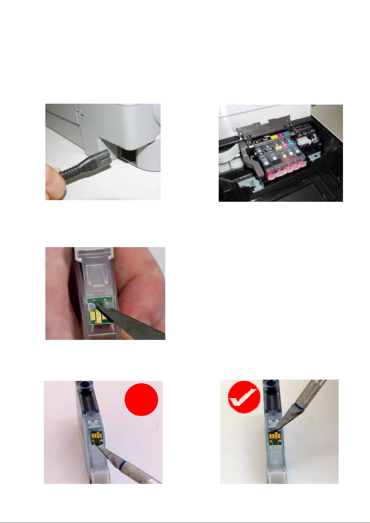
a) Turn on your printer and open the cover. The cartridge holder will move to the
cartridge change position. Remove power cable from the back of your printer.
Remove the cartridges from the printer.
b) Using a Stanley knife or sharp blade remove the two plastic lugs which hold the
chip in place. The chips are colour specific so ensure you do not mix them
up as they will not work if they are attached incorrectly
c) Gently lift the chip from the cartridge. Never pry off the chip particularly from
the top of the chip as you may damage the sensitive electronics on the rear of
the chip.
X
8
Page 9

d) Examine the rear of the chip to ensure the LED has not been damaged or cut
off.
LED
Missing
LED
undamaged cartridge chip damaged cartridge chip
e) Place the chip onto the corresponding coloured CISS cartridge, ensuring that
the small plastic lugs are inserting into the chip holes. Use a soldering iron
gently
melt the plastic lugs to hold the chip in place.
f) Repeat stepsb) & e) for each of the cartridges on your CISS
Alternatively you can fit the cartridge chips using thin double sided tape although
the preferred method is with a soldering iron.
If attaching the chip with double sided tape, please cut the tape and attach it to the
rear of the chip as pictured below. DO NOT COVER ATTACHMENT HOLES OR
LED.
LED
Attachment holes
Thin double sided
tape
rear of cartridge chip pictured
9
Page 10

4) Preparing your ink reservoirs
g
a) Carefully remove the small travel plugs on the CISS, leaving the filler plug in
place.
Travel
Plu
Filler
Plug
b) Using the syringe, remove any excess ink from the inner air balance chamber.
The chamber does not have to be completely empty for the CISS to function
correctly. Removing excess ink simply helps reduces the air pressure drawing
back from the cartridges and can assist in preventing air to develop in the ink
feeder tubes. The excess ink can be discarded or replaced into the reservoir
via the filler plug. Please refer to refilling instruction page 22 .
Air
Balance
Chamber
Never have the filler plug removed at the same time as the travel plug. The air
balance chamber has a hole in the base linking it to the main ink reservoir.
Having both plugs removed at the same time will re-fill the air balance chamber
with ink.
Air
Balance
Chamber
(shown in blue)
10
Page 11

THE FOLLOWING STEPS ARE VERY IMPORTANT FOR ALL CANON PRINTERS.
5) Inserting the silicone nozzle seals.
a) Remove the printer head from your printer by lifting the print head lock arm.
The print head will then lift out
b) Remove the 5 silicone seals from your kit. During manufacture 2 seals may
stick together giving the appearance of a single seal.
c) Ensure each seal is clean by placing each seal onto the small pieces of double
sided tape provided. Please ensure both sides of the seal are cleaned. Use the
tweezers provided to remove each seal from the tape ensuring no dust, dirt or
oils are passed onto it from your hands.
d) Carefully place each silicone nozzle seal into position around each of the
printer heads as shown.
11
Page 12
e) Incorrectly placed silicone seals can cause poor printing quality. Please
ensure that the silicone seals do not move from position when inserting the
cartridges. These seals must not cover the silver printer head.
f) Reinsert the print head (with silicone seals now fitted) back into the printer
6)
Inserting the cartridges
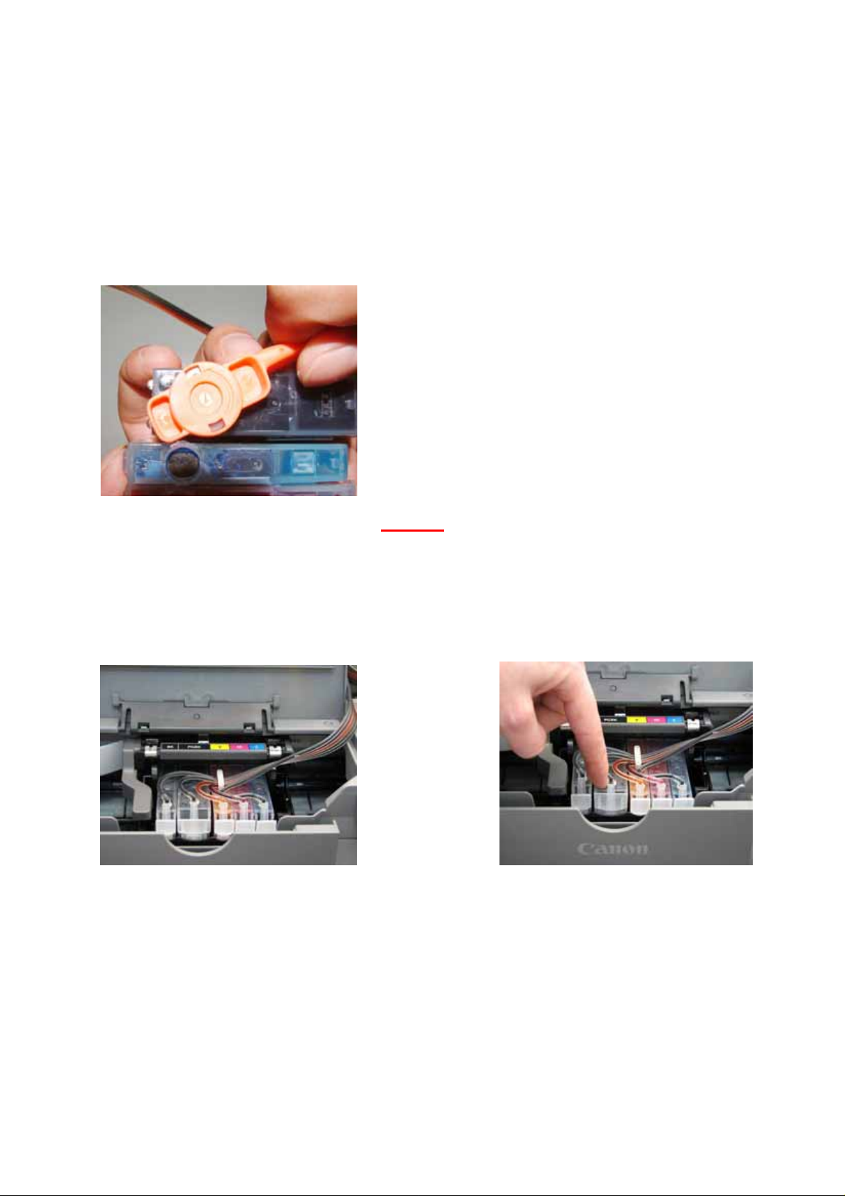
a) Remove the orange cartridge cover from each of your new cartridges. This is
done by slowly moving the clip in an anticlockwise direction. Beware that
during transit ink may build up in this cap and will release when the cover is
removed, so have a tissue or similar handy to absorb the excess ink.
b) If installing you CISS onto an MP530 printer please proceed to section 10)
on page 19 of this manual.
c) For all other printers, insert the new cartridges into your printer as a group.
Please ensure that the cartridges are placed in the correct coloured cartridge
holder. Gently push down on the cartridges to click them into place
12
Page 13
7) Tube set up (IP Series Only)
X
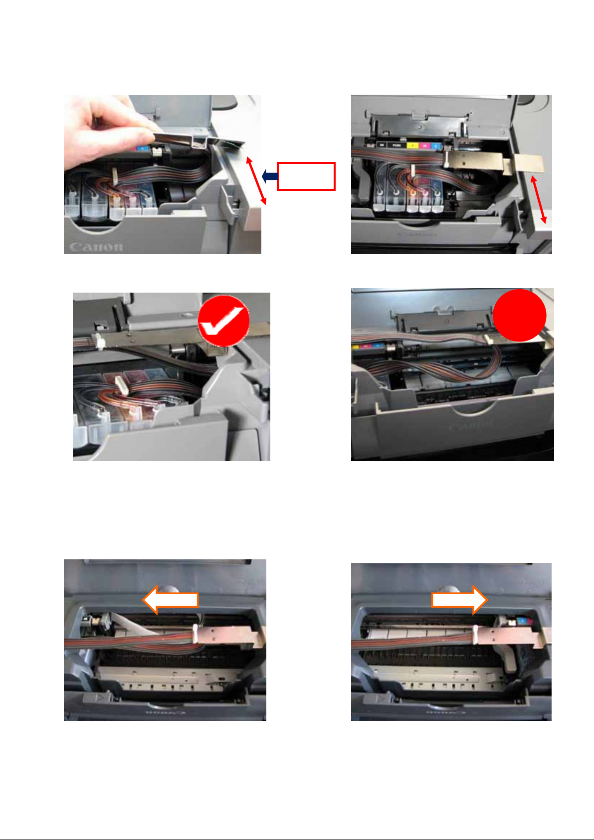
a) Remove the backing to the double sided tape and attach the metal tube
support arm approximately 6cm from the front as pictured below.
6cm
Please be careful not to twist the tubing before connecting it to the printer.
b) Adjustments to the tube length may be required. To check this, move the
cartridge holder left and right to each end of the printer. It should reach both
ends with ease. Check that the tubing is neither too long nor too short. The
tubing must not interfere with the printer data wire nor should it fall down into
the paper support or cause any interference to the head movement.
c) If required, adjust the tube length by gently pulling the silicone tubing in the
direction required. DON’T HAVE THE TUBING FITTED TOO TIGHTLY.
13
Page 14
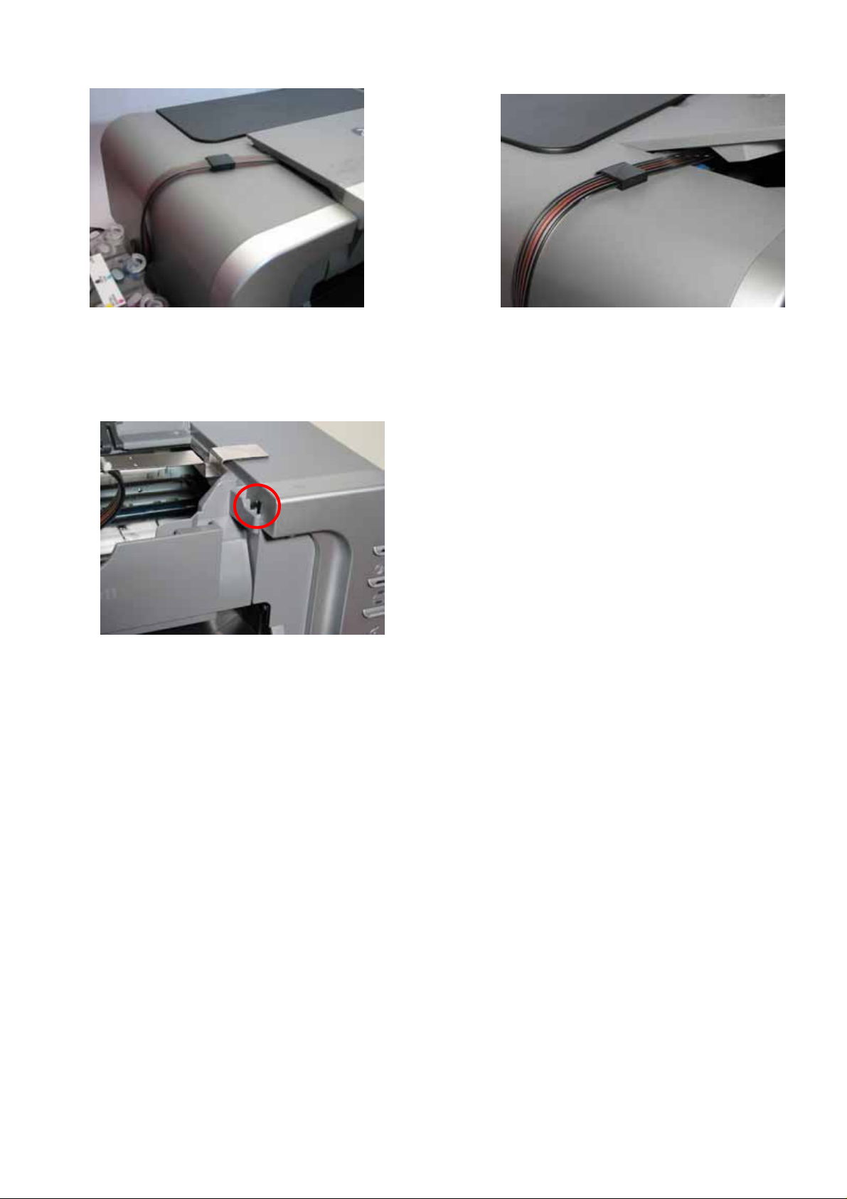
d) Peel off the backing tape to the tube connection and place it as pictured below.
Once again please ensure not to twist or bend the tubing.
e) Place the spare travel or filler plug in the printer lid sensor button. This will keep
the switch permanently activated as your printer lid will no longer close enough
to activate this switch.
Please refer to section 11) Finishing Touches on 22 to complete the
installation process
14
Page 15
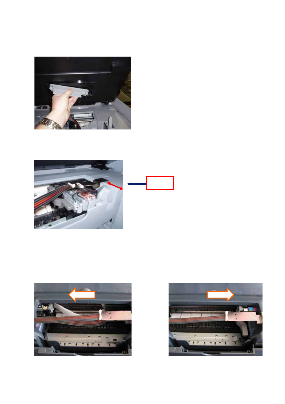
8) Tube set up (MP800 and MP830 only)
a) Using a Phillips head screwdriver, remove the plastic cartridge bay sealing
cover from the scanner lid. Store this cover away with your printer manuals
etc, in the event you need to re-attach it for printer warranty return issues.
b) Remove the backing to the double sided tape and attach the metal tube
support arm approximately 4cm from the front as pictured below.
4cm
c) Adjustments to the tube length may be required. To check this, move the
cartridge holder left and right to each end of the printer. It should reach both
ends with ease. Check that the tubing is neither too long nor too short. The
tubing must not interfere with the printer data wire nor should it fall down into
the paper support or cause any interference to the head movement.
d) If required, adjust the tube length by gently pulling the silicone tubing in the
direction required. DON’T HAVE THE TUBING FITTED TOO TIGHTLY.
15
Page 16

e) Run the tubing as per the following exiting through the front of the printer.
Please refer to section 11) Finishing Touches on 22 to complete the
installation process.
16
Page 17
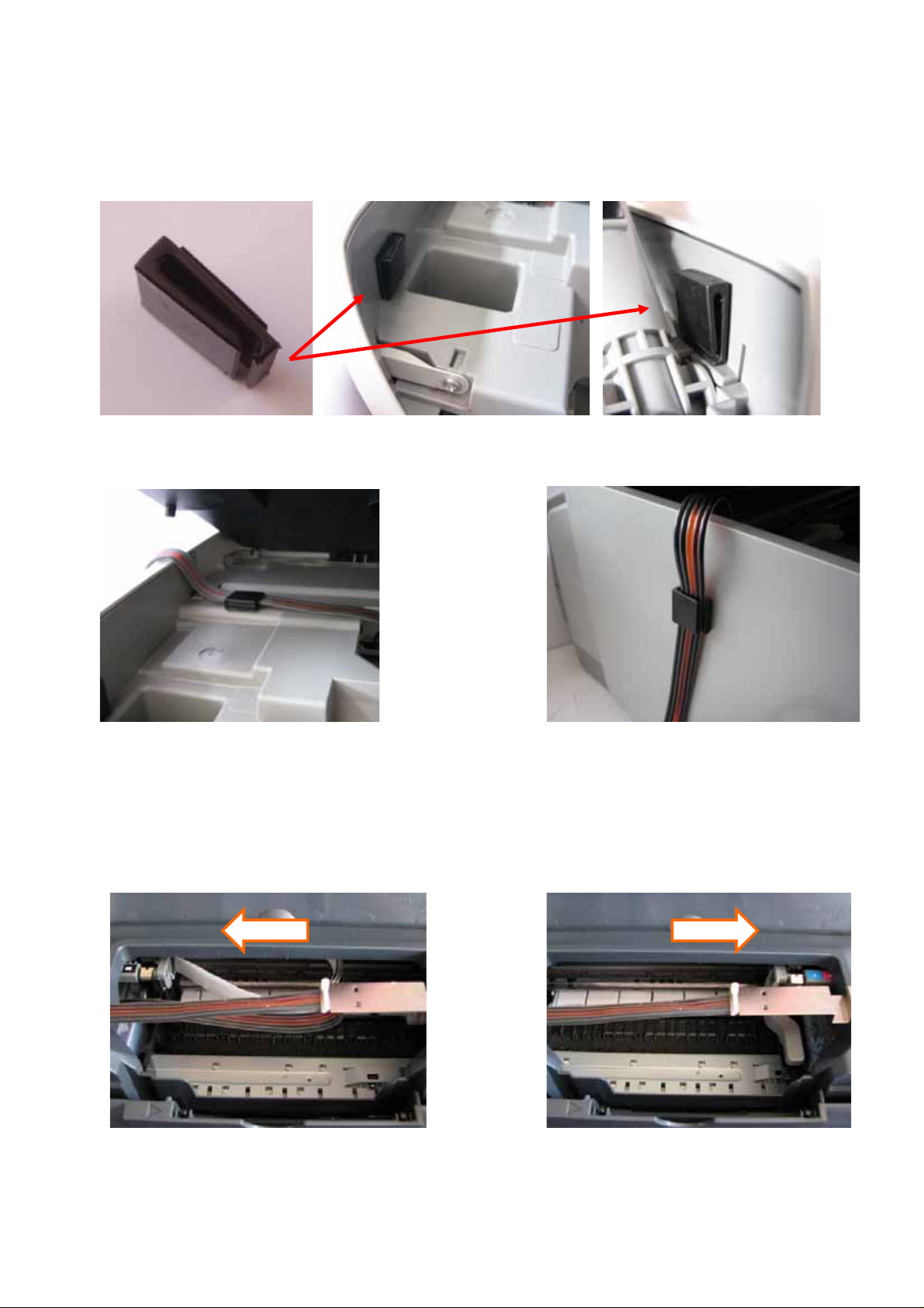
9) Tube set up (MP500 ONLY)
a) Attach the two black clips as pictured below. The clips have a piece of double
sided tape attached, simply remove the backing and attach. This will prevent
the scanner lid from crushing the silicone tubing.
b) Run the tubing as per the following photographs
c) Adjustments to the tube length may be required. To check this, move the
cartridge holder left and right to each end of the printer. It should reach both
ends with ease. Check that the tubing is neither too long nor too short. The
tubing must not interfere with the printer data wire nor should it fall down into
the paper support or cause any interference to the head movement.
d) If required, adjust the tube length by gently pulling the silicone tubing in the
direction required. DON’T HAVE THE TUBING FITTED TOO TIGHTLY.
17
Page 18

e) Close the scanner lid and check that the ink flow will not be restricted by the lid.
Please note after the installation of the CISS the printer may
not registered that
the lid is closed. If this occurs please place some tape across the trigger to
keep it activated.
Please refer to section 11) Finishing Touches on 22 to complete
the installation process
18
Page 19
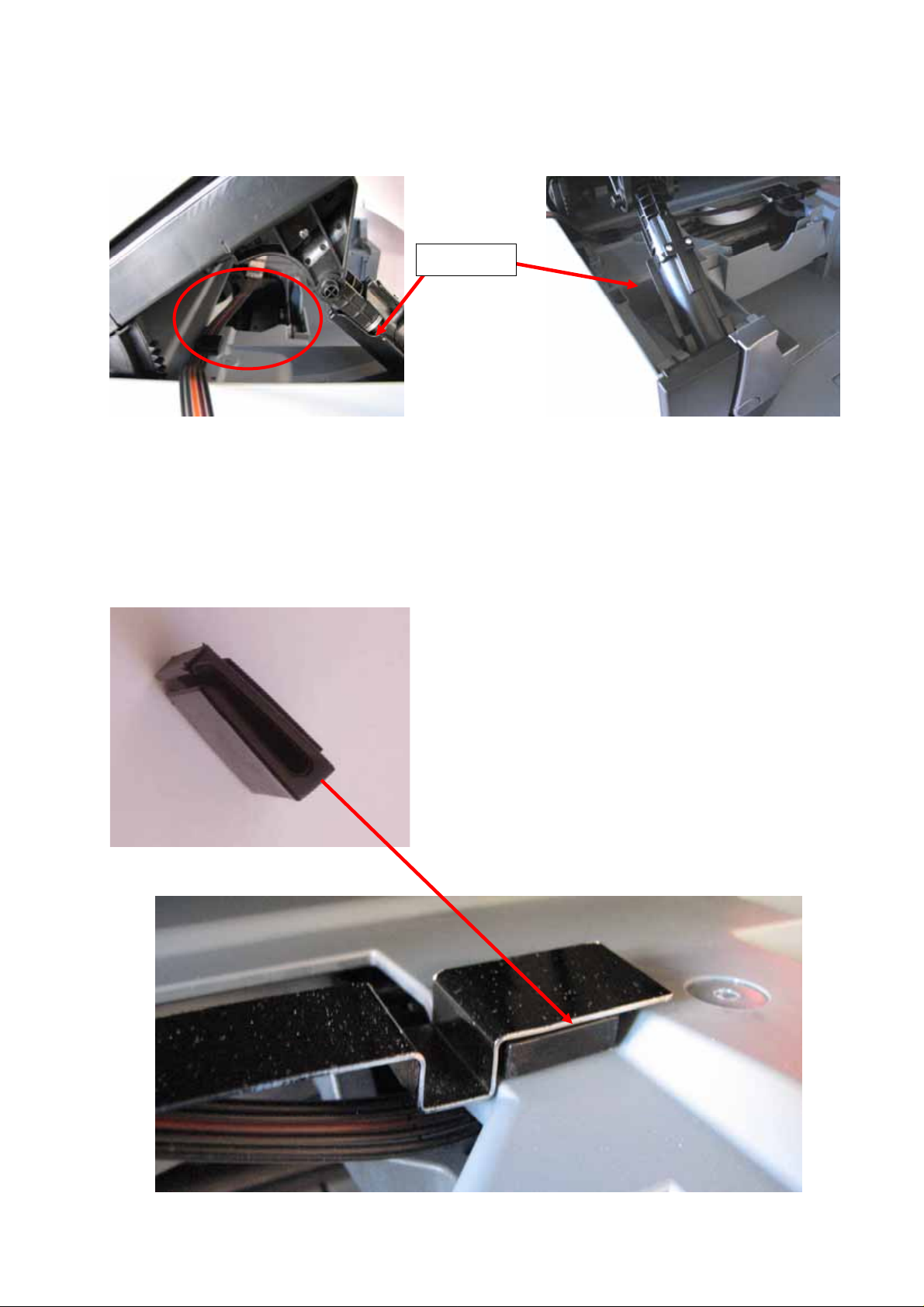
10) Tube set up (MP530 only)
a) Feed the cartridges into the printer through the scanner lid swing arm (as
depicted below) and click the cartridges in place as per the IP4200 Manual
section 6 ‘inserting the cartridges’.
Swing arm
b) Attach a raiser clip to the printer (using double sided tape) as show in the
following photographs. The metal tube arm is then attached to the clip also
using the double sided tape. The design of the MP530 does not allow you to fit
the metal tube arm to the printer body without using the raiser clip. The
positioning of the metal tubing holder is very important as if it is not in the
correct spot the lid of the scanner will not close.
The raiser clip is angled to
compensate for the downward
angle of the printer moulding
Ensure when attaching the raiser
clip that it is attached so that when
the metal tube arm is fitted it lays
flat and not on an angle
.
19
Page 20
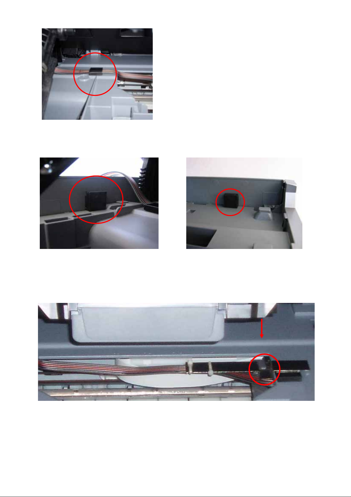
c) Attach tubing holder clip at the following point
d) Attach the large raiser clips to the left and right side of the printer case. This
allows the scanner lid to close without crushing the feeder tubes.
Left Side Right side
e) The scanner lid has moulded plastic parts which should fit into the recess of the
metal tubing rod. If it does not, move the metal tube arm to a position where
the plastic fits into the recess when the lid is closed.
20
Page 21
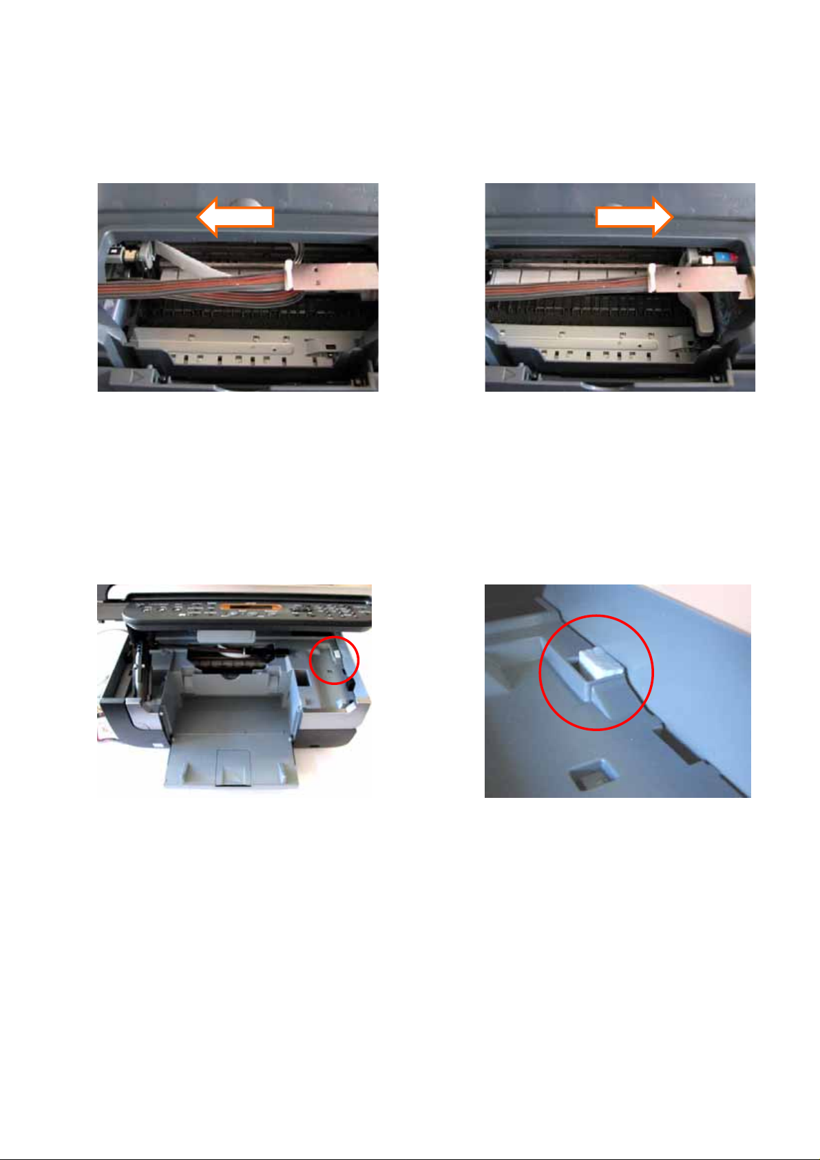
f) Adjustments to the tube length may be required. To check this, move the
cartridge holder left and right to each end of the printer. It should reach both
ends with ease. Check that the tubing is neither too long nor too short. The
tubing must not interfere with the printer data wire nor should it fall down into
the paper support or cause any interference to the head movement.
g) If required, adjust the tube length by gently pulling the silicone tubing in the
direction required. DON’T HAVE THE TUBING FITTED TOO TIGHTLY.
h) As the scanner lid is being held ajar by an extra centimetre it may be necessary
to activate the lid sensor switch. Cut a small piece of Styrofoam (around 1cm
from the CISS packaging. Use the foam to push down and activate the lid
sensor located at the right hand corner of the printer as pictured below.
2)
Please refer to section 11) Finishing Touches on 22 to complete
the installation process
21
Page 22
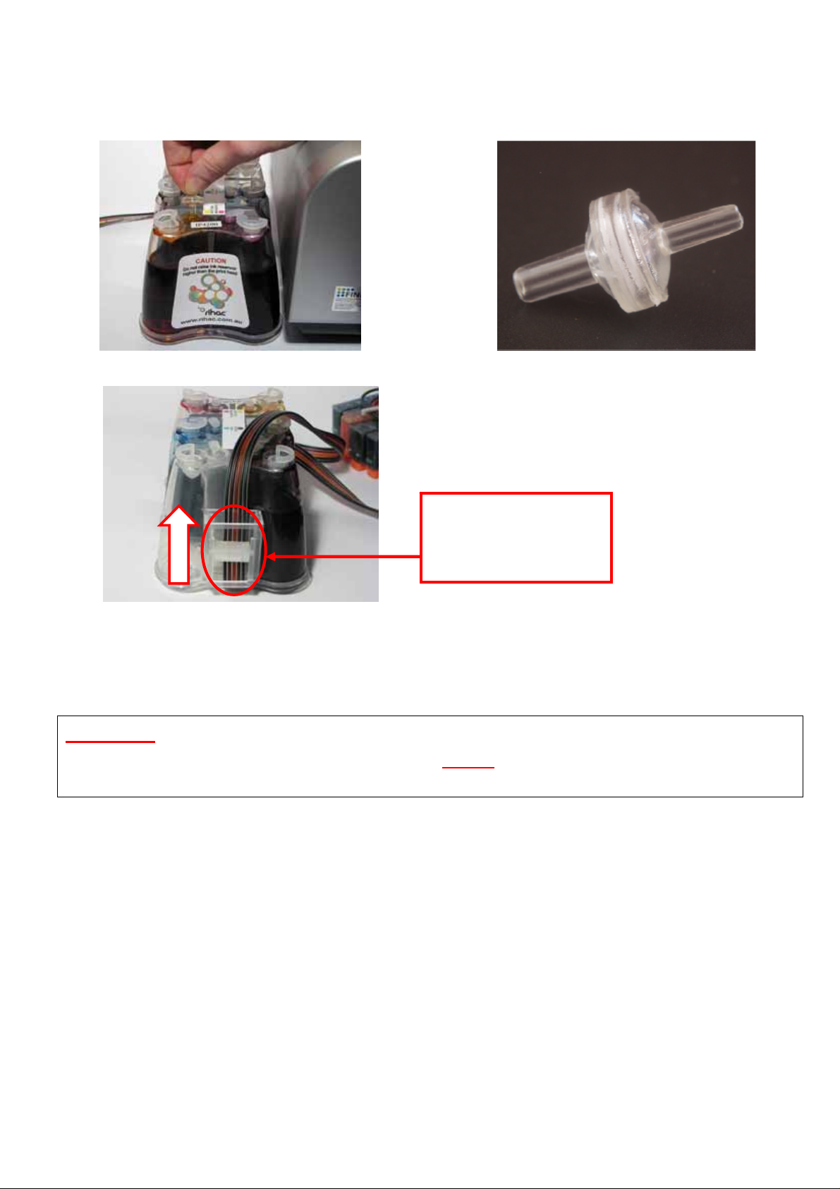
11) Final touches (all models)
a) Place the CISS unit on the left hand side of your printer and Insert all the air
filters into the top of each air balance chamber. The larger end should be
inserted into the air balance chamber.
b) Release the tube clamp on the front of the CISS by rolling it up.
Release the tube
clamp by rolling
the roller up.
c) Reinsert power cable to the rear of your printer. Perform a head clean and
nozzle check as per steps 1)a) & 1)b). Please note that this may need to be
performed several times to ensure excess air is removed.
CAUTION - NEVER HAVE THE INK RESERVOIRS HIGHER OR LOWER
THAN THE PRINTER HEIGHT. THIS WILL EFFECT THE INK FLOW TO
YOUR PRINTER, AND CAUSE YOUR PRINTER TO FLOOD WITH INK
22
Page 23
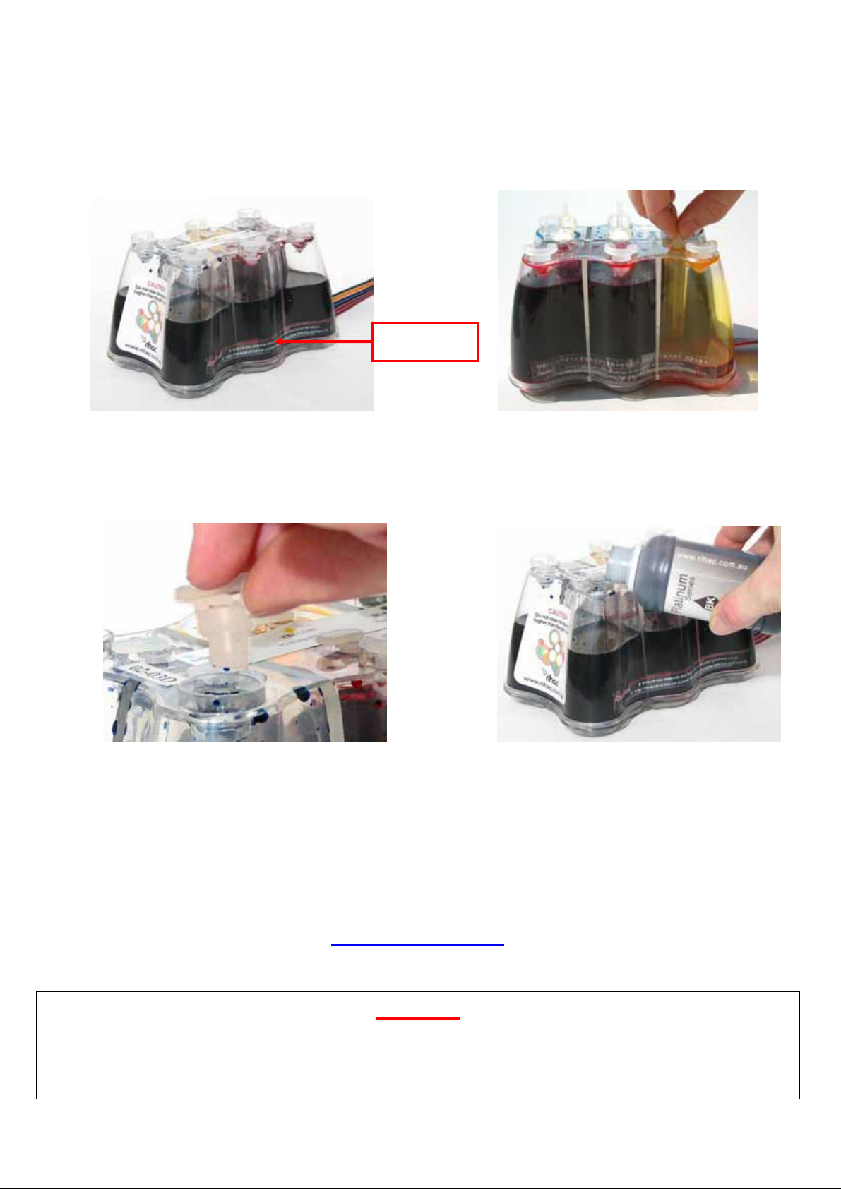
12) Refilling your CISS
a) Do not allow the ink levels to fall below the refill line. To refill each ink simply
remove the air filters and replace the travel plugs (to prevent the air balance
chambers filling with ink) for the colour in which you are refilling.
Refill Line
b) Remove the filler plug and carefully pour or syringe the correct coloured ink into
the appropriate ink reservoir. Please ensure to double check the colour with
the sticker located on the bottle and the top of the tank.
c) Replace the filler plug once filled. Remove the small travel plug replacing it
with the air filter.
DO NOT REFILL YOUR SYSTEM WITH CHEAP QUALITY IMPORT INKS!
Quality refill inks can be purchased directly from Rihac
at 157 Union Road, Ascot Vale, Vic 3032 Phone 03 9005 5555 or online at
www.rihac.com.au
Caution
To ensure ink does not fill the air chamber when refilling your unit, it is
imperative that the air filter is replaced with the travel plug.
Do not have both the travel plug and refill plug removed at the same time.
23
Page 24
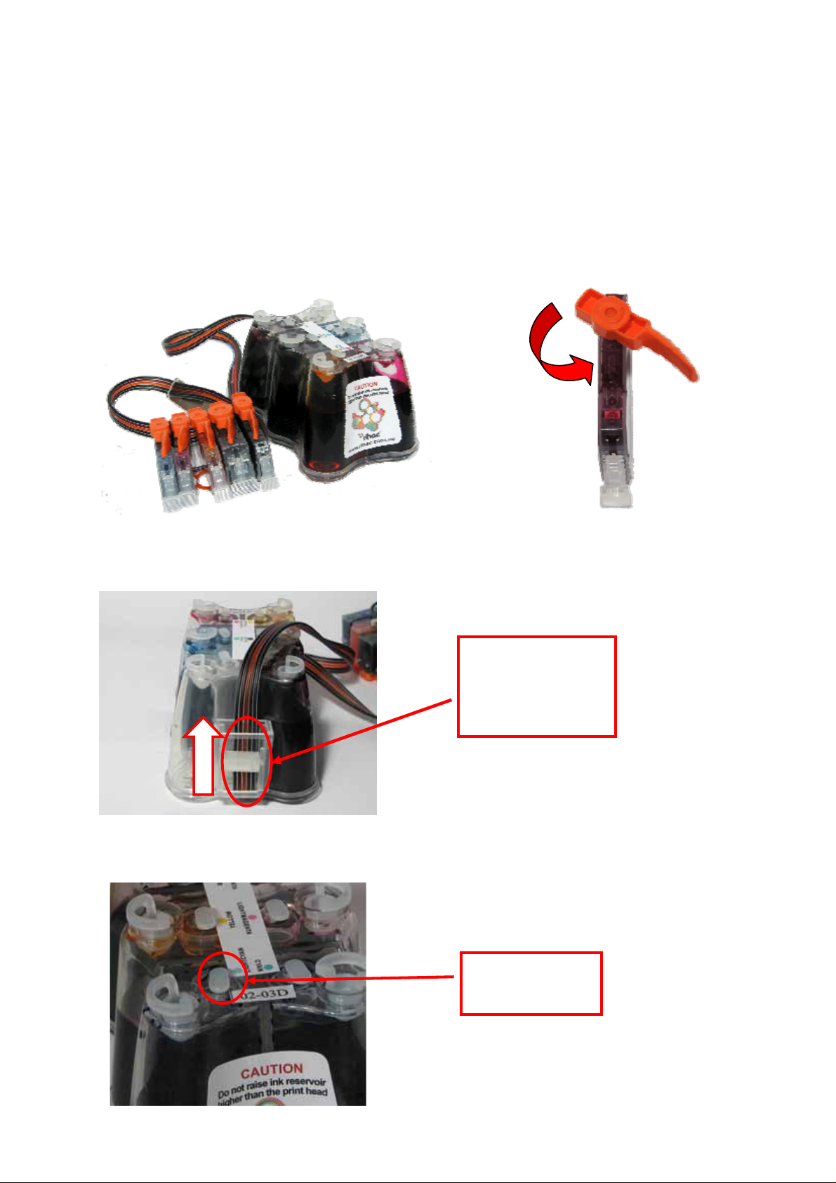
13) Priming
a) Only prime your CISS if excess air (5cm or more) is present in the tubing. It is
recommended that priming is conducted in a suitable workspace. Please
ensure to wear gloves & have some tissues handy to soak up excess ink
before undertaking any priming.
b) Remove the CISS from the box and place it on a suitable work area with the
cartridges upside down. Remove the cover from the cartridge you are priming
by twisting it anticlockwise.
c) Release the roller clamp by rolling it up – This step is very important!
Release the
tube clamp by
rolling up the
roller down
d) Remove the travel plug from the corresponding cartridge ink chamber.
Travel plug
(air chamber)
24
Page 25
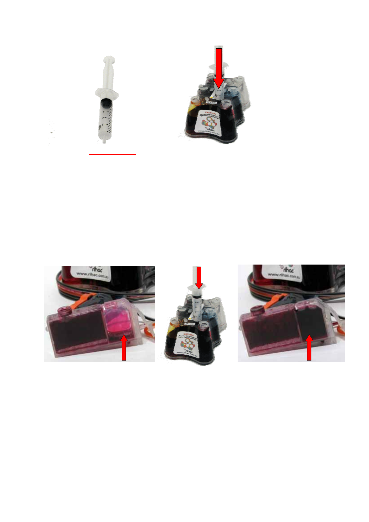
e) Draw air into the syringe (DO NOT ATTACH A NEEDLE) then place it in the
hole left by the removed travel plug.
f) Push down very slowly
on the syringe, pushing air into the reservoir.
It is very important that you push down very slowly (use the gauge on the side
of the syringe and do not push down more than 1ml at a time). The ink
reservoir becomes pressurized as you push air into it. Forcing too much air in
too quickly can result in ink squirting back up and out the air balance tube at
force if the syringe is removed without drawing back on it a little.
As you gently push down on the syringe, ink will feed through the tubing forcing
excess air through the silicone tubing and into the cartridge. As you do this you
will notice the cartridge filling with ink.
cartridge has too much air ink level rises
Once the cartridge is near full slowly draw back 1 cm on the syringe
Carefully remove the syringe from the reservoir to prevent ink back flowing up
the air balance tube due to a build up of pressure.
BEWARE
Ink & air bubbles will come out of the sponge. Use a tissue to absorb any ink.
g) Replace the air filter or travel plug. Re-attach the cartridge cover until you have
finished priming to prevent accidental ink spills.
Repeat steps 13)d) – e) for all colours requiring priming.
25
Page 26
14) Cartridge chip disable - Low ink.
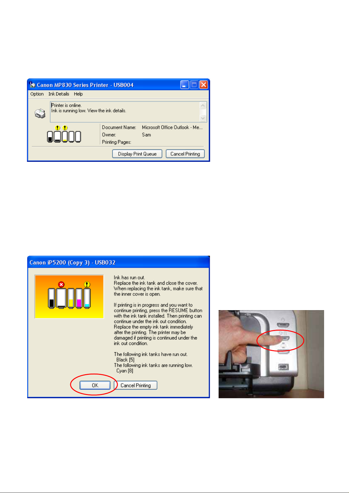
a) Flashing printer cartridges
Your canon cartridges will flash when the chip thinks that ink is running low. You will
find that the following message will appear when printing. Please continue to print
as normal when this message appears.
b) Canon messages – Turning off the printer status monitor
Your printer will proceed through a series of steps informing you that your ink
cartridges need replacing. Please follow the steps as displayed carefully. Note
these steps will need to be performed once for each individual cartridge. Once all
cartridges have proceeded through these steps, your printer status monitor will be
turned off and these messages will no longer appear.
Warning Message #1
You do not need to remove or replace the cartridge when this message appears.
Simply press the printer resume button (or ‘OK’ button for the MP series printers)
followed by OK button on the pop up screen.
26
Page 27
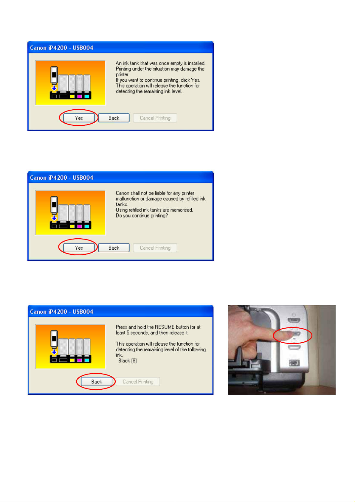
Warning message #2
Warning Message #3
Press Yes to continue.
Press Yes to continue.
Warning Message #4
Press and hold the resume/paper feed button (or the stop/reset button for the MP
series printers) for 5 seconds then release it. This will disable your printer’s
capability of reading ink levels for the individual cartridge. This is not a permanent
feature and should you return to using genuine cartridges the ink monitoring will
return when new cartridges are installed.
Please remember that this procedure will need to be carried out once for each of
the cartridges.
27
Page 28

15)
Trouble Shooting
Please contact rihac
tm
on (+61)3 9005 5555 If any of the following
trouble shooting suggestions do not fix your problems.
DO NOT CONTACT THE PLACE OF PURCHASE
a) Leaking Ink
If your CISS appears to be leaking from the cartridges, please ensure that you
do not have the ink reservoirs placed higher then the printer level. The CISS
works on a vacuum and if raised gravity will take over and flood you printer.
Ensure that you installed the silicone seals as section 5) of this manual.
Failure to install the seals can result in ink seepage.
b) Poor Print Quality
i) Bad print nozzle check.
If you are having problems when performing nozzle checks please
ensure that the small silicone seals have not moved out of place when
inserting the cartridges. They must not be interfering with the print head.
Not enough ink!
ii) If you are finding that colours seem to be missing or are printing poorly
please ensure that you have placed the air valves into the travel plug
holes as per section 11)a). If you have done this please check that the
roller clamp on the back of your CISS is released (ie rolled to the top) as
per section 11)a).
iii) If your unit has excess air in the silicone tubing please perform a deep
head clean followed by a nozzle check. If this does not remove the air
from the tubing please refer to the priming instructions on page 24.
Too much ink!
iv) Please ensure that you do not have your ink reservoir placed higher than
the printer level. The CISS works on a vacuum and if raised higher than
the printer head, gravity will take over and flood you printer
v) Check your printer settings to ensure you have the correct setting for the
paper you are using. If you choose photo paper when using plain paper
or vice versa the print will be affected as these settings determine the
amount of ink dispersed onto the paper.
c) Abnormal Grinding Noises.
If your printer is making abnormal sounds or the printer head seems to be
struggling to move from one end to the other please readjust the metal bracket
which is holding the silicone tubing and check the length of the tubing as per
page 13).
28
Page 29

d) Ink Tank Error.
If your printer is stating that an ink tank error has occurred please check the
following if the message does not identify the problem cartridge ;
i) Check the ink feed tubing is neither too tight nor too loose as per page 13.
.
ii) Unclick and re-click all cartridges whilst in the cartridge change position. This
will temporarily activate all the LED lights on the cartridges. Any cartridge
LED which does not activate (either flash or remain constant) is either
physically damaged or attached incorrectly.
If the above does not assist you please make your way through the following
trouble shooting chart.
16) Trouble Shooting Chart
i) Open the printer cover and remove the plug holding down the printer lid
sensor button. This will allow the cartridges to move to the cartridge change
position.
ii) Unclick only the 8bk cartridge so that the chip is no longer contacting the chip
reader however is still seated in the cartridge bay.
iii) Re insert the printer lid sensor plug and close the printer lid. An error
message will pop up on the screen. Follow the chart to diagnose the error.
29
Page 30

Does the printer still display
‘Ink tank errors have occurred’
on the screen?
YES
Re-click the cartridge back
into position and repeat the
steps in section 16) for the
next cartridge in sequence
.
Something is interfering with
the chip or the chip is faulty.
Please check the LED is not
damaged & is clean of ink.
Insert the cartridge & test the
printer again.
NO
Does the error message
indicate that the cartridge is
not being recognised?
YES
PRINTING
Congratulations you have
fixed your problem!
Are you able to resume
YES
Congratulations you have
fixed your problem
NOT PRINTING
Replace the LED with a new one
from another cartridge of the
same colour then repeat process.
printing?
NO
Check the position of the chip on the
cartridge ensuring it is horizontal. Clean
the chip & LED with a damp tissue. If the
problem presets contact RIHAC
30
Page 31
g
17)
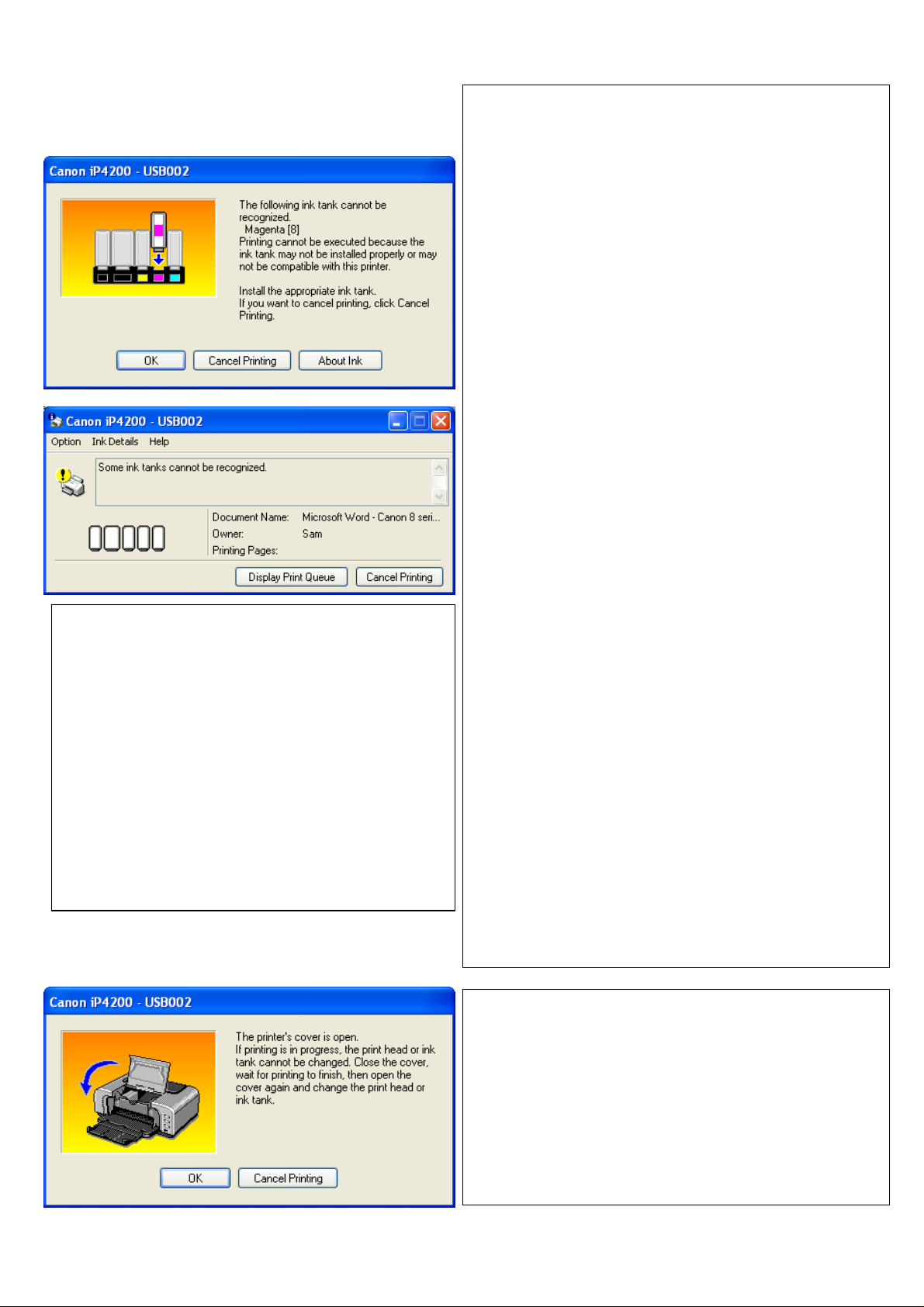
Canon Error Messages
When your printer turns on it performs a
check of the LED lights emitting from the
cartridge chips. This is done when the
cartridges are at the left most position. The
LED light shines through the clear plastic of
the cartridge to the sensor. If the sensors
cannot detect the light the printer will produce
an error message similar to the one pictured
above. If this happens check the cartridges to
make sure nothing physical impacting on the
LED. The most common explanation is a
missing LED, accidently cut off when
removing the chips from the OEM cartridges
If one or more of your ink cartridges
cannot be recognised, please ensure that
the cartridges are clicked into position
and/or the chips are correctly placed on
the cartridges.
The most common cause of this issue is
the blockage or damage of the LED as
per page 9.
Ensure the printer lid is closed when
checking cartridge recognition. Ambient
light in some situations can affect the
LED sensors. Failure to close the lid
while testing can result in cartridge
recognition error messages.
To check that the LED’s have not been
damaged, bring the cartridges to the
change position. Once in position unclick
and re-click into position all the
cartridges. If the LED light of a cartridge
is not functioning (flashing or constant) it
is most likely that the chip is faulty or
damaged. In this case the chip may need
to be replaced.
In unusual cases this message may
appear if the chips have been mixed up
and fitted to the incorrect CISS cartridge.
(i.e. Yellow OEM cartridge chip on a Blue
CISS cartridge). The solution in this case
is to remove all chips and re-attach to
OEM cartridges to identify which chip
belon
s to each coloured cartridge
Ensure that the printer senor has been
pushed down and secured using a piece
of blu-tack or tape as per section
31
Page 32
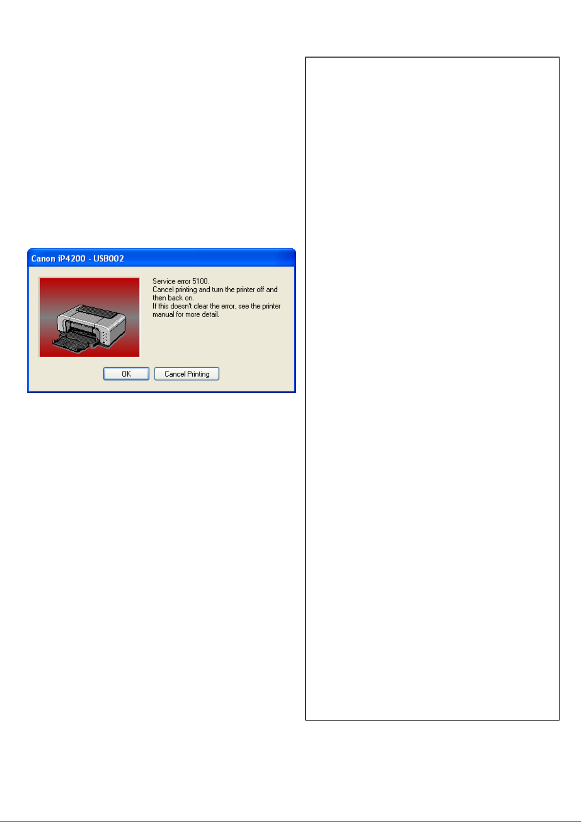
Service error 5100 will occur if you
have the silicone tubing fitted too tightly
on your printer. Please check the
tubing by follow steps 7)b) on page 13
again carefully. You will then need to
turn off and on your printer at the
power button.
Service error 6502 generally means
that your cartridge chips cannot be
recognised. The primary causes of this
error message are:
1- Covering of the LED light at the
back of the chip
2- Incorrect chip positioning on the
cartridge. Again Ensure that no
tape, glue etc is covering or
impeding LED on the rear of the
chips.
3- The lid of the printer is open
whilst testing – This will cause
the ambient light to interfere with
the LED lights which are checked
as the print head moves from left
to right.
4- The LED on one or more of the
cartridges has been damaged
when removing it from the
original cartridge
5- The chips have been mixed up
and fitted to the incorrect CISS
cartridge. (i.e. Yellow OEM
cartridge chip on a Blue CISS
cartridge). These chips are
colour specific and need to be
fitted to the corresponding
coloured CISS cartridge
6- Ink is covering the cartridge chip
or a sensitive area of the
cartridge and preventing the LED
light sensor from functioning
32
Page 33

33
Page 34

18) Warranty
Please note that your CISS has a manufactures warranty of 3 months from
date of purchase. Your warranty will be void if the system is incorrectly handled.
This warranty does not cover printer hardware. Please ensure to retain your
purchase receipt along with a copy of your nozzle check to assist with
processing your claim
19)
Warning
• Keep out of reach of children
• Do not drink ink
• Avoid ink contact with eyes
• Store between 15-35°C
• Do not store in direct sunlight
• Once your CISS is installed
NEVER raise it above your printer.
* Please note that our inks are completely compatible with your Canon printer but are
not manufactured by Canon.
Copyright 2007
rihac
tm.
All rights reserved all brand names, trademarks and photos
are property of their respective holders and are used for reference only.
34
Page 35

35
Page 36

• CIS Systems
• High Grade UV Dye Inks
• Pigment Inks
• Blank Media
157 Union Road,
Ascot Vale, Vic 3032
Web: www.rihac.com.au
Email: [email protected]
Ph: (+613) 9005 5555
FAX: (+613) 9326 1655
36
 Loading...