

SERVICE
MANUAL
Color
COPYRIGHT 2006 CANON INC. CANON imageRUNNER C5180/4580/4080 REV. 0 PRINTED IN U.S.A.
AUGUST 2006
REV. 0
imageRUNNER
C5180/C4580/C4080
Series
DU7-1174-000

Application
This manual has been issued by Canon Inc. for qualified persons to learn technical theory, installation,
maintenance, and repair of products. This manual covers all localities where the products are sold. For this reason,
there may be information in this manual that does not apply to your locality.
Corrections
This manual may contain technical inaccuracies or typographical errors due to improvements or changes in
products. When changes occur in applicable products or in the contents of this manual, Canon will release technical
information as the need arises. In the event of major changes in the contents of this manual over a long or short
period, Canon will issue a new edition of this manual.
The following paragraph does not apply to any countries where such provisions are inconsistent with local law.
Trademarks
The product names and company names used in this manual are the registered trademarks of the individual
companies.
Copyright
This manual is copyrighted with all rights reserved. Under the copyright laws, this ma nual may not be copied,
reproduced or translated into another language, in whole or in part, without the written co nsent of Canon Inc.
COPYRIGHT © 2001 CANON INC.
Printed in Japan
Caution
Use of this manual should be strictly supervised to avoid disclosure of confidential information.
Symbols Used
This documentation uses the following symbols to indicate special information:
Symbol Description
Indicates an item of a non-specific nature, possibly classified as Note, Caution, or
Warning.
Indicates an item requiring care to avoid electric shocks.
Indicates an item requiring care to avoid combustion (fire).
Indicates an item prohibiting disassembly to avoid electric shocks or problems.
Indicates an item requiring disconnection of the power plug from the electric outlet.
Indicates an item intended to provide notes assisting the understanding of the topic in
Memo
question.
Introduction
REF.
Indicates an item of reference assisting the understanding of the topic in question.
Provides a description of a service mode.
Provides a description of the nature of an error indication.

Introduction
The following rules apply throughout this Service Manual:
1. Each chapter contains sections explaining the purpose of specific functions and the relationship between electrical and mechanical systems with reference to the timing of operation.
In the diagrams, represents the path of mechanical drive; where a signal name accompanies the
symbol, the arrow indicates the direction of the electric signal.
The expression "turn on the power" means flipping on the power switch, closing the front door, and closing
the delivery unit door, which results in supplying the machine with power.
2. In the digital circuits, '1'is used to indicate that the voltage level of a given signal is "High", while '0' is used
to indicate "Low".(The voltage value, however, differs from circuit to circuit.) In addition, the asterisk (*) as
in "DRMD*" indicates that the DRMD signal goes on when '0'.
In practically all cases, the internal mechanisms of a microprocessor cannot be checked in the field.
Therefore, the operations of the microprocessors used in the machines are not discussed: they are explained
in terms of from sensors to the input of the DC controller PCB and from the output of the DC controller PCB
to the loads.
The descriptions in this Service Manual are subject to change without notice for product improvement or other
purposes, and major changes will be communicated in the form of Service Information bulletins.
All service persons are expected to have a good understanding of the contents of this Service Manual and all
relevant Service Information bulletins and be able to identify and isolate faults in the machine."

Contents
Contents
Chapter 1 Introduction
1.1 System Construction......................................................................................... 1-1
1.1.1 System Configuration with Pickup/Delivery Accessories [USA]......................... 1-1
1.1.2 System Configuration with Printing/Transmission Accessories [USA].............. 1-2
1.1.3 Functions of Printing/Transmission Accessories ............................................. .. ... 1-3
1.1.4 Overview of Printing/Transmitting Accessories. .................................................... 1-3
1.2 Product Specifications........................................................... ........................... 1-5
1.2.1 Names of Parts ...........................................................................................................1-5
1.2.1.1 External View ........................................................................................................................ 1-5
1.2.1.2 Cross Section........................................................................................................................ 1-7
1.2.2 Using the Machine .....................................................................................................1-9
1.2.2.1 Turning On the Power Switch............................................................................................. 1-9
1.2.2.2 Points to Note About Turing Off the Main Power Switch ............................................. 1-10
1.2.2.3 Control Panel ...................................................................................................................... 1-13
1.2.3 User Mode Items ......................................................................................................1-13
1.2.3.1 Common Settings............................................................................................................... 1-13
1.2.3.2 Timer Settings..................................................................................................................... 1-16
1.2.3.3 Adjustments and Cleaning................................................................................................ 1-16
1.2.3.4 Report Settings ................................................................................................................... 1-17
1.2.3.5 System Settings.................................................................................................................. 1-18
1.2.3.6 Copy Settings...................................................................................................................... 1-21
1.2.3.7 Communications Settings ................................................................................................. 1-21
1.2.3.8 Mail Box Settings................................................................................................................ 1-23
1.2.3.9 Address Book Settings ...................................................................................................... 1-23
1.2.4 User Maintenance ....................................................................................................1-24
1.2.4.1 Cleaning............................................................................................................................... 1-24
1.2.4.2 Inspection ............................................................................................................................ 1-26
1.2.5 Safety .........................................................................................................................1-27
1.2.5.1 CDRH Regulations............................................................................................................. 1-27
1.2.5.2 Laser safety......................................................................................................................... 1-28
1.2.5.3 Handling the Laser Assembly........................................................................................... 1-28
1.2.5.4 Safety of Toner ................................................................................................................... 1-29
1.2.5.5 Notes when handling a lithium battery............................................................................ 1-30
1.2.5.6 Notes at Replacing/Disposing the Fixing Unit................................................................ 1-30
1.2.5.7 Notes before it works serving........................................................................................... 1-30
1.2.6 Product Specifications .............................................................................................1-31
1.2.6.1 Type and Functions............................................................................................................ 1-31
1.2.7 Function List ..............................................................................................................1-32

Contents
1.2.7.1 Print Speed ......................................................................................................................... 1-32
1.2.7.2 Print Size............................................................................................................................. 1-38
1.2.7.3 Others .................................................................................................................................. 1-39
1.2.7.4 Reader Unit Specifications............................................................................................... 1-40
Chapter 2 Installation
2.1 Making Pre-Checks ........................................................................................... 2-1
2.1.1 Points to Note.................................................................................... ........................ 2-1
2.1.2 Spatial Requirements ................................................ ................................ ............... 2-3
2.1.3 Order of Installing Accessories ............... ............................... ................................. 2-5
2.1.4 Checking the Contents ................... ............................................................ ............. 2-6
2.2 Unpacking and Installation............................................................................... 2-8
2.2.1 Points to Note About Relocating the machine...................................................... 2-8
2.2.2 Mounting the Reader Unit (Color Image Reader E1/F1).................................... 2-8
2.2.3 Mounting the Transfer Cleaning Unit ................................................................... 2-13
2.2.4 Fitting the Toner Container in Place..................................................................... 2-15
2.2.5 Fitting the Drum Unit in Place ............................................................................... 2-16
2.2.6 Fitting the Secondary Transfer Outside Roller Unit in Place............................ 2-18
2.2.7 Cassette Setup ....................................................................................................... 2-20
2.2.8 Other Work .............................................................................................................. 2-21
2.2.9 Dealing with power code mount............................................................................ 2-22
2.2.10 Connecting the Power Cord ............................................................................... 2-24
2.2.11 Adjustment of Fixing Assembly .......................................................................... 2-24
2.2.12 Checking the Image Margin ............................................................................... 2-24
2.2.13 Adjustment of Left Margin of Image .................................................................. 2-24
2.2.14 Adjustment of the Margin along Leading Edge of Image................................ 2-27
2.2.15 Adjustment of the Image Area (non-image width) ........................................... 2-27
2.2.16 Setting the Auto Gradation Adjustment ............................................................ 2-27
2.3 Checking the Connection to the Network ..................................................... 2-28
2.3.1 Summary.................................................................................................................. 2-28
2.3.2 Checking the Network Connection ...................................................................... 2-28
2.3.3 Ping Operation ........................................................................................................ 2-28
2.4 Troubleshooting the Network......................................................................... 2-28
2.4.1 Summary.................................................................................................................. 2-28
2.4.2 Checking the Connection of Network Cable ...................................................... 2-28
2.4.3 Making a Check Using a Loopback Address...................................................... 2-28
2.4.4 Making a Check Using a Local Host Address ................................................... 2-28
2.5 Installing the Copy Tray.................... ........................................................... ... 2-29
2.5.1 Checking the Attachments (Copy Tray-N1)........................................................ 2-29
2.5.2 Turning Off the Host Machine............................................................................... 2-29
2.5.3 Installation Procedure............................................................................................. 2-30

Contents
2.6 Installing the Card Reader................................................. ............................ 2-31
2.6.1 Checking Contents (Card Reader-D1) ........... ............................... ....................... 2-31
2.6.2 Installation Procedures....... ............................... ............................... ....................... 2-31
2.6.3 Installation Procedure in the imageWARE Accounting Manager (henceforth:
iWAM) environment............................ ............................................................ .............. 2-33
2.7 Installing the Original Tray............................................................................. 2-33
2.7.1 Checking Contents (Document Tray-J1)..... ............................... ......................... 2-33
2.7.2 Installation Procedures ................. ............................... ............................... ............ 2-34
2.8 Installing the Key Switch Unit................................................. ....................... 2-34
2.8.1 Checking Contents (Key Switch Unit-A2)....................... ............................... ....... 2-34
2.8.2 Installation Procedures ................. ............................... ............................... ............ 2-35
2.8.3 Checking After the Installation ................................. ............................... .............. 2-36
2.9 Installing the Voice Guidance Kit.................................................................. 2-37
2.9.1 Checking Contents (Voice Guidance Kit-A2) ................................. ..................... 2-37
2.9.2 Turning off the Host Machine.............. .. ............................................................ ..... 2-38
2.9.3 Installation Procedures....... ............................... ............................... ....................... 2-38
Chapter 3 Basic Operation
3.1 Construction.............................................................................. ......................... 3-1
3.1.1 Functional Construction ....... ............................... ............................... ....................... 3-1
3.2 Basic Sequence.............................. ........................................................... ........ 3-2
3.2.1 Basic Sequence When the Power Is ON ........................ ............................... ....... 3-2
3.2.2 Basic Sequence of Operations ......................................................................... ....... 3-4
Chapter 4 Basic Operations (As a Printer)
4.1 Construction of the Electrical Circuitry........................................................... 4-1
4.1.1 Configuration of Main PCBs.......................................... ................................ ........... 4-1
4.1.2 DC Controller PCB 1 (IMG).................................. .................................................... 4-2
4.1.3 DC Controller PCB 2 (MAISY) ................................. ............................... ................ 4-4
4.2 Basic Sequence.............................. ........................................................... ........ 4-6
4.2.1 Basic Sequence of Operations ......................................................................... ....... 4-6
4.2.2 Basic Sequence of Operations ......................................................................... ....... 4-7
Chapter 5 Main Controller
5.1 Construction.............................................................................. ......................... 5-1
5.1.1 Configuration/Functions..................................................................... ....................... 5-1
5.2 Construction of the Electrical Circuitry........................................................... 5-3
5.2.1 Main Controller Circuit Board (MAIN)............................................................ ......... 5-3

Contents
5.2.2 SRAM Circuit Board................ ............................... ............................... .................... 5-4
5.3 Start-Up Sequence............................................................................................ 5-5
5.3.1 Overview......................................................... ............................... ............................. 5-5
5.3.2 Start-Up Sequence ...... .. ............................................................ ............................... 5-5
5.4 Actions when HDD Error................................................................................... 5-9
5.4.1 E602 Details........................... ............................................................ ........................ 5-9
5.5 Image Processing.......................................................... .................................. 5-13
5.5.1 Overview of the Flow of Image Data.................................................................... 5-13
5.5.2 Reader Input Image Processing........................................................................... 5-14
5.5.3 Printer Output Image Processing ......................................................................... 5-15
5.5.4 Compression, Decompression, and Edit Processing Blocks ........................... 5-16
5.6 Flow of Image Data ..................................................... .................................... 5-17
5.6.1 Flow of Image Data for Copier Functions............................................................ 5-17
5.6.2 Flow of Image Data for Box Functions................................................................. 5-18
5.6.3 Flow of Image Data for SEND Functions............................................................ 5-19
5.6.4 Flow of Image Data for Fax Transmission Functions........................................ 5-20
5.6.5 Flow of Image Data for Fax Reception Functions.............................................. 5-21
5.6.6 Flow of Image Data for PDL Functions................................................................ 5-22
5.7 Parts Replacement Procedure.................... ................................................... 5-23
5.7.1 Main Controller Box ................................................................................................ 5-23
5.7.2 Main Controller PCB (main) .................................................................................. 5-23
5.7.3 Main Controller PCB (sub R-A) ............................................................................. 5-27
5.7.4 Main Controller PCB (sub PDRM-A) .................................................................... 5-28
5.7.5 Main Controller PCB (sub SJ-A) ........................................................................... 5-28
5.7.6 Main Controller PCB (sub LAN-A) ........................................................................ 5-29
5.7.7 Main Controller PCB (sub RB-A) .......................................................................... 5-30
5.7.8 SRAM PCB .............................................................................................................. 5-31
5.7.9 Boot ROM PCB ....................................................................................................... 5-31
5.7.10 Image Memory (SDRAM) .................................................................................... 5-32
5.7.11 HDD ......................................................................................................................... 5-33
5.7.12 Controller Fan ........................................................................................................ 5-34
Chapter 6 Original Exposure System
6.1 Construction........................................................................................................ 6-1
6.1.1 Specifications, Control Mechanisms, and Functions........................................... 6-1
6.1.2 Major Components................................. ................................ ............................... .... 6-2
6.1.3 Construction of the Control System .................................... ................................... 6-4
6.1.4 Reader Controller PCB........... ............................... ............................... .................... 6-5
6.2 Basic Sequence................................................................................................. 6-6
6.2.1 Basic Sequence of Operation at Power-On........................................ .................. 6-6
6.2.2 Basic Sequence of Operation in Response to a Press on the Start Key......... 6-7

Contents
6.3 Various Control Mechanisms.......................................................................... 6-9
6.3.1 Controlling the Scanner Drive System ....................................................................6-9
6.3.1.1 Overview................................................................................................................................ 6-9
6.3.1.2 Controlling the Scanner Motor.......................................................................................... 6-10
6.3.2 Enlargement/Reduction ..........................................................................................6-11
6.3.2.1 Changing the Magnification in Main Scanning Direction.............................................. 6-11
6.3.2.2 Changing the Magnification in Sub Scanning Direction ............................................... 6-11
6.3.3 Controlling the Scanning Lamp ..............................................................................6-11
6.3.3.1 Overview.............................................................................................................................. 6-11
6.3.3.2 Scanning Lamp................................................................................................................... 6-12
6.3.3.3 Turning On and Off the Scanning Lamp......................................................................... 6-12
6.3.4 Detecting the Size of Originals ..............................................................................6-12
6.3.4.1 Identifying the Size of Originals........................................................................................ 6-12
6.3.4.2 Points of Measurement Used for Original Size Identification...................................... 6-13
6.3.4.3 Overview of Operation....................................................................................................... 6-15
6.3.5 Dirt Sensor Control ..................................................................................................6-17
6.3.5.1 Stream Reading Dust Detection Control ........................................................................ 6-17
6.3.5.2 White Plate Dust Detection Control................................................................................. 6-19
6.3.6 Image Processing ....................................................................................................6-21
6.3.6.1 Overview.............................................................................................................................. 6-21
6.3.6.2 CCD Drive............................................................................................................................ 6-22
6.3.6.3 CCD Gain Correction, Offset Correction ........................................................................ 6-22
6.3.6.4 CCD Output A/D Conversion............................................................................................ 6-22
6.3.6.5 Outline of Shading Correction .......................................................................................... 6-22
6.3.6.6 Shading Adjustment........................................................................................................... 6-23
6.3.6.7 Shading Correction ............................................................................................................ 6-23
6.4 Parts Replacement Procedure................................. ..................................... 6-24
6.4.1 Copyboard Glass .....................................................................................................6-24
6.4.2 Exposure Lamp ........................................................................................................6-24
6.4.3 Reader Controller PCB ...........................................................................................6-25
6.4.4 Interface PCB ...........................................................................................................6-27
6.4.5 Inverter PCB .............................................................................................................6-28
6.4.6 CCD Unit ...................................................................................................................6-29
6.4.7 Scanner Motor ..........................................................................................................6-30
6.4.8 ADF Open/Close Sensor ........................................................................................6-31
6.4.9 Scanner HP Sensor .................................................................................................6-32
6.4.10 Original Sensor .......................................................................................................6-33
6.4.11 Cooling Fan .............................................................................................................6-33
6.4.12 Scanner Drive Cable .............................................................................................6-34
Chapter 7 Image Processing System
7.1 Digital Image Processing............................ ..................................................... 7-1

Contents
7.1.1 Overview......................................................... ............................... ............................. 7-1
7.1.2 Shading Correction........................ ............................... ............................... ............. 7-1
Chapter 8 Laser Exposure
8.1 Construction........................................................................................................ 8-1
8.1.1 Specifications, Control Mechanisms, and Functions........................................... 8-1
8.1.2 Major Components................................. ................................ ............................... .... 8-2
8.1.3 Construction of the Control System .................................... ................................... 8-3
8.2 Basic Sequence................................................................................................. 8-4
8.2.1 Basic sequence of operation............................................................. ...................... 8-4
8.3 Various Control................................................................................................... 8-5
8.3.1 Controlling the Laser Activation Timing ................................................................. 8-5
8.3.1.1 ON/OFF Control................................................................................................................... 8-5
8.3.1.2 Controlling Synchronization in Main Scanning Direction............................................... 8-9
8.3.1.3 Controlling Synchronization in Sub Scanning Direction............................................... 8-10
8.3.2 Controlling the Intensity of Laser Light ................................................................ 8-10
8.3.2.1 APC Control........................................................................................................................ 8-10
8.3.2.2 PWM Control....................................................................................................................... 8-11
8.3.3 Controlling the Laser Scanner Motor ................................................................... 8-12
8.3.3.1 Laser scanner motor control............................................................................................. 8-12
8.3.3.2 Laser Scanner Motor Speed Change Control............................................................... 8-13
8.3.4 Controlling the Laser Shutter ................................................................................ 8-14
8.3.4.1 Laser shutter control.......................................................................................................... 8-14
8.3.5 Correcting Image Displacement ........................................................................... 8-15
8.3.5.1 Outline.................................................................................................................................. 8-15
8.3.5.2 Timing of Color Displacement Detection/Correction .................................................... 8-16
8.3.5.3 Detecting/Correcting Color Displacement in Sub Scanning Direction....................... 8-17
8.3.5.4 Detecting/Correcting the Angle in Main Scanning Direction....................................... 8-18
8.3.5.5 Detecting/Correcting Color Displacement in Main Scanning Direction ..................... 8-20
8.3.5.6 Detecting/Correcting Changes in the Reproduction Ratio in Main Scanning Direction 821
8.4 Parts Replacement Procedure.................... ................................................... 8-23
8.4.1 Laser Unit ................................................................................................................. 8-23
Chapter 9 Image Formation
9.1 Construction........................................................................................................ 9-1
9.1.1 Specifications, Control Mechanisms, and Functions........................................... 9-1
9.1.2 Major Components of the Image Formation System........................................... 9-3
9.1.3 Charging Specifications ............................... ............................... ............................. 9-4
9.2 Image Formation Process................................................................................ 9-7
9.2.1 Image Formation Process (general)....... ............................... ............................... .. 9-7

Contents
9.2.2 Image Formation Process (image formation)........................................ ................ 9-8
9.2.3 Image Formation Process (transfer)........................ ............................... ................ 9-9
9.3 Basic Sequence.............................. ........................................................... ...... 9-10
9.3.1 At Power-On (1) ............................................................................ ........................... 9-10
9.3.2 At Power-On (2) ............................................................................ ........................... 9-11
9.3.3 During Copying/Printing Operations (normal speed) ................ ......................... 9-12
9.3.4 Making Copies/Prints (half speed) ...................................... ............................... ... 9-13
9.3.5 After Replacing the Drum Unit (D-UNIT).............................................................. 9-14
9.3.6 Printing Originals Containing a Color Page...................................................... ... 9-15
9.4 Driving and Controlling the Image Formation System .............................. 9-16
9.4.1 Driving and Controlling the Image Formation System and the High-Voltage System
9-16
9.5 Image Stabilization Control................................................... ......................... 9-18
9.5.1 Outline of Image Quality Control .............................. ............................................. 9-18
9.5.2 Automated Image Stabilization Control................................................................ 9-18
9.5.3 ATR Control....................... ............................... ............................... ......................... 9-22
9.5.4 Discharge Current Level Control..................... .. .................................................... 9-23
9.5.5 ATVC Control (transfer bias level correction)....... ............................................... 9-23
9.5.6 PASCAL Control (image gradation)..................................................................... . 9-24
9.5.7 SALT-Dmax Control (development characteristics correction)......................... 9-25
9.5.8 SALT-Dhalf Control (development characteristics correction).......................... 9-26
9.5.9 Auto Gradation Control .............................. ................................ ............................. 9-27
9.6 Drum Unit .................................................................................. ....................... 9-29
9.6.1 Outline of the Drum Unit .........................................................................................9-29
9.6.1.1 Outline of the Drum Unit.................................................................................................... 9-29
9.6.1.2 Drum Receptacle Presence / Absence Detection......................................................... 9-29
9.6.1.3 Drum Unit (D-UNIT) Drive Control................................................................................... 9-30
9.6.2 Developing Assembly ..............................................................................................9-31
9.6.2.1 Construction of the Developing Assembly...................................................................... 9-31
9.6.2.2 Controlling the Developing Bias....................................................................................... 9-32
9.6.3 Auxiliary Brush ..........................................................................................................9-34
9.6.3.1 Construction of the Auxiliary Brush ................................................................................. 9-34
9.6.3.2 Controlling the Auxiliary Bias............................................................................................ 9-35
9.6.4 Charging Mechanism ..............................................................................................9-39
9.6.4.1 Construction of the Charging Mechanism ...................................................................... 9-39
9.6.4.2 Controlling the Charging Bias........................................................................................... 9-40
9.7 Toner Container................................................................................. .............. 9-42
9.7.1 Outline of the Toner Container... ............................................................ ................ 9-42
9.7.2 Toner Receptacle Presence / Absence Detection..................... ......................... 9-42
9.7.3 Controlling the Toner Container Drive....................................... ........................... 9-43
9.7.4 Checking the Level of Toner ...... ............................... ............................... .............. 9-44
9.7.5 Controlling the Supply of Toner........................................................... .................. 9-45

Contents
9.8 Transfer Unit..................................................................................................... 9-46
9.8.1 Outline of the Transfer Unit ................................................................................... 9-46
9.8.1.1 Outline of the Transfer Unit.............................................................................................. 9-46
9.8.1.2 Transfer Unit Drive Control............................................................................................... 9-47
9.8.2 Controlling the Transfer Bias ................................................................................. 9-48
9.8.2.1 Transfer Bias Control......................................................................................................... 9-48
9.8.3 Cleaning .................................................................................................................... 9-50
9.8.3.1 Intermediate Transfer Belt (ITB)...................................................................................... 9-50
9.8.3.2 Secondary External Roller................................................................................................ 9-51
9.8.3.3 Waste Toner Collection Mechanism............................................................................... 9-51
9.8.4 Separation Mechanism .......................................................................................... 9-52
9.8.4.1 Separation........................................................................................................................... 9-52
9.9 Parts Replacement Procedure.................... ................................................... 9-54
9.9.1 Drum ITB Motor ....................................................................................................... 9-55
9.9.2 Drum Drive Unit ....................................................................................................... 9-56
9.9.3 Drive Roller .............................................................................................................. 9-57
9.9.4 Developing Motor (Bk/Y/M/C) ............................................................................... 9-58
9.9.5 Secondary Transfer Unit ........................................................................................ 9-59
9.9.6 Intermediate Transfer Unit ..................................................................................... 9-60
9.9.7 Transfer Cleaning Unit ........................................................................................... 9-62
9.9.8 Intermediate Transfer Belt ..................................................................................... 9-62
9.9.9 Intermediate Transfer Belt Tension Roller .......................................................... 9-66
9.9.10 Primary Transfer Roller ........................................................................................ 9-66
9.9.11 Secondary Transfer External Roller ................................................................... 9-67
9.9.12 Secondary Transfer Internal Roller .................................................................... 9-69
9.9.13 Toner Container Drive Unit .................................................................................. 9-70
9.9.14 Waste Toner Detection PCB ............................................................................... 9-71
9.9.15 Feedscrew Rotation Sensor ................................................................................ 9-73
9.9.16 Tone Container Motor .......................................................................................... 9-75
9.9.17 Waste Toner Feedscrew Case ........................................................................... 9-77
9.9.18 Pattern Reader Unit .............................................................................................. 9-79
9.9.19 Auto Registration Sensor PCB ............................................................................ 9-80
9.9.20 SALT Sensor .......................................................................................................... 9-81
Chapter 10 Pickup/Feeding System
10.1 Construction...................................... ........................................................... ... 10-1
10.1.1 Specifications, Control Mechanisms, and Functions....................................... 10-1
10.1.2 Arrangement of he Units...................................................................................... 10-2
10.1.3 Arrangement of Rollers ........................................................................................ 10-3
10.1.4 Diagram of the Paper Paths................................................................................ 10-4
10.1.5 Arrangement of Sensors...................................................................................... 10-5
10.1.6 Arrangement of the Clutches and Solenoids.................................................... 10-6

Contents
10.1.7 Route of Dive..... ............................... ................................ ...................................... 10-7
10.2 Basic Sequence............................................................................................. 10-8
10.2.1 Basic Sequence of Operations at Power-On.......................... ........................... 10-8
10.2.2 Basic Sequence of Operations in Response to a Press on the Start Key.... 10-8
10.3 Detecting Jams.............................................................................................. 10-9
10.3.1 Delay Jams .............................................................................................................10-9
10.3.1.1 Delay Jam in the Cassette Pickup Assembly .............................................................. 10-9
10.3.1.2 Delay Jam Outside the Cassette Pickup Assembly.................................................... 10-9
10.3.2 Stationary Jams ....................................................................................................10-10
10.3.2.1 Stationary Jams.... ......................................... ... ... ... ......................................... ... .... ... ..... 10-10
10.3.2.2 Stationary Jams at Power-On ........ ... ... ... .......................................... ... ... ... .................. 10-11
10.4 Cassette........................................................................................................ 10-12
10.4.1 Identifying the Paper Size................................................................................... 10-12
10.4.2 Detecting the Level of Paper.............................................................................. 10-14
10.5 Cassette Pick-Up Unit ................................................................................ 10-16
10.5.1 Outline.................................................................................................................... 10-16
10.5.2 Basci Sequence of Operations .......................................................................... 10-17
10.6 Manual Feed Pickup Unit........................................................................... 10-18
10.6.1 Outline.................................................................................................................... 10-18
10.6.2 Basic Sequence of Operations .......................................................................... 10-19
10.6.3 Identifying the Size of Paper.............................................................................. 10-19
10.6.4 Detecting the Presence/Absence of Paper...................................................... 10-20
10.6.5 Detecting the Last paper..................................................................................... 10-21
10.7 Registration Unit.......................................................................................... 10-22
10.7.1 Outline.................................................................................................................... 10-22
10.8 Duplex Feeding Unit................................................................................... 10-24
10.8.1 Outline.................................................................................................................... 10-24
10.8.2 Controling Horizontal Registration..................................................................... 10-25
10.8.3 Face-Down Delivery, A4, 5 Sheets in Circulation........................................... 10-26
10.8.4 Face-Down Delivery, A3, 3 Sheets in Cirucilation.......................................... 10-29
10.9 Delivery......................................................................................................... 10-32
10.9.1 Delivery.................................................................................................................. 10-32
10.9.2 Movement in the Direction of Face-Down Delivery ........................................ 10-33
10.9.3 Movement in the Direction of Face-Up Delivery ............................................. 10-34
10.9.4 Movement for CenterTray delivery.................................................................... 10-35
10.9.5 Moement for Copy Tray Dievyer........................................................................ 10-35
10.10 Parts Replacement Procedure................................................................ 10-36
10.10.1 Cassette Pickup Unit .........................................................................................10-36
10.10.2 Cassette Size Detection Unit ...........................................................................10-36
10.10.3 Pre-registration Roller .......................................................................................10-37
10.10.4 Registration Upper Roller .................................................................................10-38

Contents
10.10.5 Re-pickup Roller ................................................................................................ 10-39
10.10.6 Pickup Roller ...................................................................................................... 10-40
10.10.7 Feed Roller ......................................................................................................... 10-41
10.10.8 Separation Roller .............................................................................................. 10-41
10.10.9 Cassette Pickup Motor ..................................................................................... 10-42
10.10.10 Cassette Retry Paper Sensor ....................................................................... 10-43
10.10.11 Cassette Paper Sensor .................................................................................. 10-45
10.10.12 Cassette Paper Level Sensor (A/B) ............................................................. 10-47
10.10.13 Slide Resistor ................................................................................................... 10-50
10.10.14 Cassette Pickup Solenoid .............................................................................. 10-51
10.10.15 Manual Feed Tray Unit ................................................................................... 10-52
10.10.16 Manual Feed Unit ............................................................................................ 10-52
10.10.17 Manual Feed Roller ........................................................................................ 10-53
10.10.18 Manual Feed Separation Roller .................................................................... 10-54
10.10.19 Manual Feed Last Paper Sensor .................................................................. 10-56
10.10.20 Manual Feed Sensor ...................................................................................... 10-57
10.10.21 Transparency Sensor (Front/Rear) .............................................................. 10-58
10.10.22 Manual Feed Pickup Solenoid ...................................................................... 10-58
10.10.23 Registration Motor ........................................................................................... 10-59
10.10.24 Pre-Registration Motor ................................................................................... 10-60
10.10.25 Horizontal Registration Motor ........................................................................ 10-60
10.10.26 Registration Sensor ........................................................................................ 10-62
10.10.27 Fixing/Feeder Unit ........................................................................................... 10-62
10.10.28 Pickup Vertical Path Roller ............................................................................ 10-63
10.10.29 Inside Delivery Roller ...................................................................................... 10-65
10.10.30 Fixing/Feeder Unit Open/Closed Sensor .................................................... 10-66
10.10.31 Fixing Arching Sensor .................................................................................... 10-69
10.10.32 Pickup Vertical Path Cover Open/Closed Sensor ...................................... 10-70
10.10.33 Fixing/Feeder Unit Open/Closed Detecting Switch ................................... 10-71
10.10.34 Drawer Connector (manual feed unit) .......................................................... 10-72
10.10.35 Drawer Connector (fixing/feeder unit) .......................................................... 10-72
10.10.36 Duplex Roller 1 ................................................................................................ 10-73
10.10.37 Duplex Roller 2 ................................................................................................ 10-77
10.10.38 Duplex Roller 3 ................................................................................................ 10-78
10.10.39 Duplex Roller 4 ................................................................................................ 10-80
10.10.40 Duplex Feed Motor ......................................................................................... 10-81
10.10.41 Duplex Registration Sensor ........................................................................... 10-82
10.10.42 Duplex Horizontal Registration Sensor ........................................................ 10-83
10.10.43 Duplex Pickup Sensor .................................................................................... 10-85
10.10.44 Duplex Registration Clutch ............................................................................ 10-89
10.10.45 Duplex Pickup Clutch ..................................................................................... 10-91
10.10.46 Delivery Vertical Path Unit ............................................................................. 10-93

Contents
10.10.47 Face-Down Delivery Roller 1 .........................................................................10-95
10.10.48 Face-Up Delivery Roller ..................................................................................10-98
10.10.49 Delivery Vertical Path Roller 1 .....................................................................10-100
10.10.50 Delivery Vertical Path Roller 2 .....................................................................10-101
10.10.51 Face-Down Delivery Motor ...........................................................................10-102
10.10.52 Delivery Vertical Path Motor .........................................................................10-102
10.10.53 Face-Down Delivery Sensor 1 .....................................................................10-103
10.10.54 Center Delivery Tray Full sensor .................................................................10-104
10.10.55 Face-Down Delivery Sensor 2 .....................................................................10-105
10.10.56 Delivery Vertical Path Cover Open/Closed Sensor ..................................10-106
10.10.57 Delivery Path Switching Solenoid 1 ............................................................10-106
10.10.58 Delivery Path Switching Solenoid 2 ............................................................10-106
10.10.59 Face-Down Delivery Roller 1 Drive Belt .....................................................10-107
Chapter 11 Fixing System
11.1 Construction................................................................................................... 11-1
11.1.1 Specifications, Control Mechanisms, and Functions.......................... .. ............ 11-1
11.1.2 Major Components..................................................................................... ............ 11-2
11.1.3 Control system composition...................................... ............................... ............ 11-4
11.2 Various Control Mechanisms.......................................... ............................ 11-5
11.2.1 Controlling the Speed of the Fixing Roller .........................................................11-6
11.2.1.1 Overview............................................................................................................................ 11-6
11.2.1.2 Controlling the Speed According to Paper Type ......................................................... 11-6
11.2.1.3 Fixing Arch Control........................................................................................................... 11-7
11.2.2 Controlling the Fixing Roller Temperature .........................................................11-8
11.2.2.1 Overview............................................................................................................................ 11-8
11.2.2.2 At Power-On(Fixing belt less than 100Åé)................................................................... 11-8
11.2.2.3 At Power-On(Fixing belt 100deg C or more)...... ... ... ...................................... ............ 11-10
11.2.2.4 Standby mode............. ......................................... ... ... ... .................................................. 11-12
11.2.2.5 Print mode ......................... ... .... ......................................... ... ... ... ..................................... 11 -1 3
11.2.2.6 Temperature rise at end.............................................................................................. .. 11-15
11.2.2.7 Measurements against heating of fixing tension roller............................................. 11-16
11.2.2.8 In case of recovery from sleep-mode........................................................... ............... 11-17
11.2.2.9 At Low-Power/Power Save Mode................................................................................ 11 -1 7
11.2.2.10 The service mode regarding the fixing temperature control. ........... ... .................. 11-18
11.2.3 Detecting the Passage of Paper ........................................................................11-19
11.2.3.1 Detection of paper passage.................................................................. ... ... ... ............... 11-19
11.2.4 Belting inclined Control .......................................................................................11-20
11.2.4.1 Belt Displacement Control ............................. ... ... ... ..................................................... 11-20
11.2.4.2 Belt Full Displacement Temporary Escape Mode............. ... ..................................... 11-25
11.2.5 Checking Life ........................................................................................................11-27
11.2.5.1 Lifetime Detection of Fixing Assembly Belt Unit............................. ... ........................ 11-27

Contents
11.3 Belt Pressurizing Mechanism ................................................................... 11-30
11.3.1 Pressurizing mechanism of pressure belt....................................................... 11-30
11.4 Protective Functions.................................................................................... 11-31
11.4.1 Power break due to thermo-switch operation at unusual temperature rise. 11-31
11.5 Parts Replacement Procedure................................................................... 11-32
11.5.1 Fixing Drive Unit .................................................................................................. 11-32
11.5.2 Fixing Assembly .................................................................................................. 11-33
11.5.3 Fixing Unit ............................................................................................................ 11-33
11.5.4 IH Unit ................................................................................................................... 11-40
11.5.5 Fixing Displacement Drive Unit ......................................................................... 11-42
11.5.6 Fixing Delivery Lower Unit ................................................................................. 11-44
11.5.7 Fixing Delivery Upper Unit ................................................................................. 11-45
11.5.8 Pressure Heater .................................................................................................. 11-46
11.5.9 Fixing Inlet Lower Guide .................................................................................... 11-46
11.5.10 Fixing Inlet Sensor ............................................................................................ 11-47
11.5.11 Fixing Delivery Sensor ..................................................................................... 11-47
11.5.12 Fixing Belt Position Sensor Unit ..................................................................... 11-48
11.5.13 Fixing Releasing HP Sensor ........................................................................... 11-50
11.5.14 Fixing Wrap Sensor .......................................................................................... 11-50
11.5.15 Fixing Motor Unit ............................................................................................... 11-51
11.5.16 Fixing Pressure Motor Unit .............................................................................. 11-51
11.5.17 Fixing Belt Displacement Control Motor Unit ................................................ 11-51
11.5.18 Pressure Belt Displacement Control Motor Unit .......................................... 11-53
Chapter 12 Externals and Controls
12.1 Control Panel.................................................................................................. 12-1
12.1.1 Outline..................................................................................................................... 12-1
12.1.2 LCD Processing..................................................................................................... 12-1
12.1.3 LCD Contras Adjustment ..................................................................................... 12-1
12.1.4 Functions of the Control Panel CPU.................................................................. 12-1
12.2 Counters.......................................................................................................... 12-2
12.2.1 Outline..................................................................................................................... 12-2
12.2.2 Signal-Sided Print and 2nd Side of a Double-Sided Print .............................. 12-4
12.2.3 Side of a Duplex Print (duplex model only)....................................................... 12-4
12.3 Fans........................................................................................ ......................... 12-4
12.3.1 Outline..................................................................................................................... 12-4
12.3.2 Fan Sequence ...................................................................................................... 12-6
12.4 Power Supply ................................................................................................. 12-7
12.4.1 Power Supply ......................................................................................................... 12-7
12.4.1.1 Timing of Power Supply.................................................................................................. 12-7
12.4.1.2 Wiring to Various Accessories ....................................................................................... 12-8

Contents
12.4.1.3 Power Supply Path to Reader Unit ............................................................................... 12-9
12.4.1.4 Power Supply Path in Printer ........................................ ... ... ... ..................................... 12 -1 0
12.4.1.5 Power Supply Path in Pedestal (Accessory) .................................... ... ... .................. 12-12
12.4.2 Rated Output of DC Power Supply PCB ..........................................................12-12
12.4.2.1 Rated Output of DC Power Supply PCB ... ................................................................. 12-12
12.4.2.2 Rated Output of the Optional DC Power Supply PCB................... ... ... ..................... 12-13
12.4.3 Protection Function ..............................................................................................12-14
12.4.3.1 Protective Mechanisms ...................... ... ........................................................................ 12-14
12.4.4 Backup Battery .....................................................................................................12-14
12.4.4.1 Battery for Backup........................................................................ ... .... ... ........................ 12-14
12.4.4.2 Backup Power Supply............. ... ... ......................................... ... ... ... ............................... 12-15
12.4.5 Energy-Saving Function ......................................................................................12-15
12.4.5.1 Outline.............................................................................................................................. 12-15
12.4.5.2 SNMP setup ................................... ... ... ... ......................................... .... ... ... ..................... 12-18
12.5 Parts Replacement Procedure.................................................................. 12-20
12.5.1 External Covers ....................................................................................................12-20
12.5.2 Developing Drive Unit ..........................................................................................12-29
12.5.3 High-Voltage Unit .................................................................................................12-27
12.5.4 Secondary Transfer High-Voltage Unit .............................................................12-28
12.5.5 IH Power Supply Assembly ................................................................................12-29
12.5.6 DC Power Supply Unit ........................................................................................12-29
12.5.7 Control Panel ........................................................................................................12-30
12.5.8 Control Panel LCD Unit .......................................................................................12-30
12.5.9 DC Controller Box ................................................................................................12-31
12.5.10 DC Controller PCB .............................................................................................12-32
12.5.11 Main Power Supply PCB ..................................................................................12-33
12.5.12 All-Night Power Supply PCB ............................................................................12-34
12.5.13 IH Power Supply PCB .......................................................................................12-34
12.5.14 Leakage Breaker ................................................................................................12-35
12.5.15 Relay PCB ...........................................................................................................12-35
12.5.16 DC/DC Converter PCB ......................................................................................12-36
12.5.17 AC Driver PCB ....................................................................................................12-37
12.5.18 Relay PCB 1 .......................................................................................................12-38
12.5.19 Control Panel CPU PCB ...................................................................................12-38
12.5.20 Control Panel Key Switch PCB ........................................................................12-39
12.5.21 Control Panel Inverter PCB ..............................................................................12-40
12.5.22 Environment Sensor ..........................................................................................12-41
12.5.23 Manual Feed Unit Open/Closed Sensor ........................................................12-42
12.5.24 Front Cover Open/Closed Sensor ...................................................................12-43
12.5.25 Main Power Switch ............................................................................................12-45
12.5.26 Manual Feed Unit Open/Closed Detecting Switch .......................................12-46
12.5.27 Front Cover Open/Closed Detecting Switch ..................................................12-48

Contents
12.5.28 ITB Cooling Fan ................................................................................................ 12-50
12.5.29 Face-down Tray Cooling Fan (rear/ front) ..................................................... 12-51
12.5.30 Cleaner Fan ....................................................................................................... 12-52
12.5.31 Manual Feed Cooling Fan ............................................................................... 12-52
12.5.32 Fixing Heat Discharge Fan .............................................................................. 12-53
12.5.33 Power Supply Exhaust Fan ............................................................................. 12-54
12.5.34 IH Power Supply Cooling Fan ......................................................................... 12-55
12.5.35 Delivery Cooling Fan ........................................................................................ 12-55
12.5.36 Machine Heat Discharge Fan .......................................................................... 12-55
12.5.37 Delivery Vertical Path Cooling Fan ................................................................ 12-56
12.5.38 Delivery Vertical Path Exhaust Fan ................................................................ 12-57
12.5.39 Drum Unit Drive Belt ......................................................................................... 12-58
Chapter 13 MEAP
13.1 MEAP............................................................................................................... 13-1
13.1.1 Overview................................................................................................................. 13-1
13.1.2 MEAP Counter....................................................................................................... 13-1
13.1.3 Construction of the MEAP Platform ................................................................... 13-2
Chapter 14 RDS
14.1 RDS................................................................................................. ................. 14-1
14.1.1 Application operation mode................................................................................. 14-1
14.1.2 Service Center URL and Port Specification...................................................... 14-1
14.1.3 Communication test .............................................................................................. 14-1
14.1.4 Communication log ............................................................................................... 14-1
14.1.5 Detailed Communication log ............................................................................... 14-1
14.1.6 SOAP communication function........................................................................... 14-1
14.1.7 Resend at SOAP transmission error.................................................................. 14-2
14.1.8 e-RDS setting screen ........................................................................................... 14-3
14.1.9 Sleep operation ..................................................................................................... 14-5
14.1.10 Network Setting (Maintenance)......................................................................... 14-5
14.1.11 e-RDS Setting (Maintenance)........................................................................... 14-6
14.1.12 Trouble shoot....................................................................................................... 14-7
14.1.13 Error message..................................................................................................... 14-7
Chapter 15 Maintenance and Inspection
15.1 Periodically Replaced Parts ......................................................................... 15-1
15.1.1 Periodically Replaced Parts................................................................................. 15-1
15.1.2 Reader Unit............................................................................................................ 15-1

Contents
15.1.3 Printer Unit ................................................. ............................................................ . 15-1
15.2 Durables and Consumables........................................................................ 15-2
15.2.1 Outline.................... .. ............................................................ ............................... ..... 15-2
15.2.2 Reader Unit........... ............................... ............................... .................................... 15-2
15.2.3 Printer Unit ................................................. ............................................................ . 15-2
15.3 Scheduled Servicing Basic Procedure ...................................................... 15-4
15.3.1 Scheduled Servicing Basic Procedure ..... ............................... ........................... 15-4
15.3.2 Scheduled Servicing (Reader Unit)........................ ............................................. 15-5
15.3.3 Scheduled Servicing (Printer Unit)...................................................................... 15-6
Chapter 16 Standards and Adjustments
16.1 Image Adjustments......................... ........................................................... ... 16-1
16.1.1 Standards for Image Position...................................................... ......................... 16-1
16.1.2 Checking the Image Position . ............................... ............................................... 16-1
16.1.3 Adjusting the Left/Right Margin (Cassette)............................... ......................... 16-2
16.1.4 Adjusting the Left/Right Margin (Manual Feed Tray) ...................................... . 16-4
16.1.5 Adjusting the Left/Right Margin (Side Paper Deck).......................................... 16-4
16.2 Scanning System................................................ .......................................... 16-4
16.2.1 After Replacing the CCD Unit...................... .. ...................................................... 16-4
16.2.2 After Replacing the Copyboard Glass....................... ................................ ......... 16-5
16.2.3 After Replacing the Reader Controller PCB or Initializing the RAM.............. 16-5
16.2.4 Treatment for ADF Replacement................. .. ...................................................... 16-7
16.3 Laser Exposure System............................................................................... 16-8
16.3.1 Laser Exposure System........................................................ ................................ 16-8
16.4 Image Formation System............................................................................. 16-8
16.4.1 Laser maker identification............... ............................................................. ......... 16-8
16.4.2 After Replacing the Transfer Unit........................................ ............................... . 16-8
16.4.3 After Replacing the Pattern Reading Unit.......................................................... 16-8
16.4.4 Adjustments of Tilt in Intermediate Transfer Unit Rail...................................... 16-8
16.5 Fixing System.............................................................................................. 16-11
16.5.1 Treatment after Replacement of Fixing Unit.................................................... 16-11
16.6 Electrical Components ............................................................................... 16-13
16.6.1 After Replacing the Reader Controller PCB or Initializing the RAM............ 16-13
16.6.2 Replacing DC Controller PCB 1ÅiIMGÅj ......................................................... 16-14
16.6.3 Replacing Main Controller PCB ........................................................................ 16-15
16.6.4 When Replacing the SRAM PCB...................................................................... 16-15
16.6.5 When Replacing the HDD................................................................................... 16-15
16.6.6 When Replacing the Power Supply PCB......................................................... 16-16
16.7 Pickup/Feeding System............................................................................. 16-16

Contents
16.7.1 Adjusting the Horizontal Registration When Replacing the Pickup Cassette 16-
16
16.7.2 Adjusting the Horizontal Registration When Replacing the Duplex Unit.... 16-17
Chapter 17 Correcting Faulty Images
17.1 Outline of Electrical Components............................................... ................. 17-1
17.1.1 Clutch/Solenoid ..................................................................................................... 17-1
17.1.2 Motor ....................................................................................................................... 17-1
17.1.3 Fan .......................................................................................................................... 17-5
17.1.4 Sensor ..................................................................................................................... 17-6
17.1.5 Switch .................................................................................................................... 17-11
17.1.6 Lamps, Heaters, and Others ............................................................................. 17-13
17.1.7 PCBs ..................................................................................................................... 17-15
Chapter 18 Self Diagnosis
18.1 Error Code Table ................................... ........................................................ 18-1
18.1.1 Error code tables................................................................................................... 18-1
18.2 Error Code Details......................................................................................... 18-4
18.2.1 Table of error code details................................................................................... 18-4
Chapter 19 Service Mode
19.1 DISPLAY (Status Display Mode)................................................................. 19-1
19.1.1 COPIER .................................................................................................................. 19-1
19.1.2 FEEDER ............................................................................................................... 19-16
19.2 I/O (I/O Display Mode)................................................................................ 19-17
19.2.1 Overview............................................................................................................... 19-17
19.2.2 DC-CON ............................................................................................................... 19-18
19.2.3 R-CON .................................................................................................................. 19-24
19.2.4 FEEDER ............................................................................................................... 19-26
19.2.5 SORTER............................................................................................................... 19-27
19.2.6 MN-CONT............................................................................................................. 19-37
19.3 ADJUST (Adjustment Mode)...................................................................... 19-39
19.3.1 COPIER ................................................................................................................ 19-39
19.3.2 FEEDER ............................................................................................................... 19-58
19.4 FUNCTION (Operation/Inspection Mode)................................................ 19-59
19.4.1 COPIER ................................................................................................................ 19-59
19.4.2 FEEDER ............................................................................................................... 19-71
19.5 OPTION (Machine Settings Mode)........................................................... 19-74
19.5.1 COPIER ................................................................................................................ 19-74

Contents
19.5.2 FEEDER ..............................................................................................................19-122
19.5.3 SORTER ..............................................................................................................19-122
19.5.4 BOARD ................................................................................................................19-123
19.6 TEST (Test Print Mode)........................................................................... 19-124
19.6.1 COPIER ...............................................................................................................19-124
19.7 COUNTER (Counter Mode)..................................................................... 19-128
19.7.1 COPIER ...............................................................................................................19-128
Chapter 20 Upgrading
20.1 Outline................................. ........................................................... ................. 20-1
20.1.1 Function/ Operation Overview ............ ............................... .................................. 20-1
20.1.2 Points to Note at Downloading.............................. ............................................... 20-5
20.2 Making Preparations..................................................................................... 20-5
20.2.1 Registration of System Software (System CD to SST)............................. ....... 20-5
20.2.2 Registration of System Software (SST to USB memory)................................ 20-7
20.2.3 Connection (At Using SST) ................................................................................ 20-10
20.2.4 Connection (At Using USB Memory)................................................................ 20-12
20.3 Formatting the HDD.................................................................................... 20-14
20.3.1 Formatting All Partitions...................................................................................... 20-14
20.3.2 Formatting Selected Partitions........................................................................... 20-15
20.3.3 Formatting the Partitions..................................................................................... 20-16
20.4 Downloading System Software................................................................. 20-18
20.4.1 Batch Downloading ..............................................................................................20-18
20.4.2 Downloading the System Software (Single) ....................................................20-23
20.5 Uploading and Downloading Backup Data ............................................. 20-28
20.5.1 Outline.................................................................................................................... 20-28
20.5.2 Uploading Procedure........................................................................................... 20-29
20.5.3 Download Procedures ........................................................................................ 20-32
20.6 Version Upgrade using USB ..................................................................... 20-34
20.6.1 Menu/Function Overview ................................................................................... 20-34
20.6.2 Points to Note at the Time of Operation/Use .................................................. 20-35
20.6.3 Download/Writing of System Software (Auto) ................................................ 20-36
20.6.4 Download of System Software (Auto, or Selectable) .................................... 20-37
20.6.5 Download of System Software (Overwriting) .................................................. 20-39
20.6.6 Format HDD ......................................................................................................... 20-40
20.6.7 Other Functions ................................................................................................... 20-41
Chapter 21 Service Tools
21.1 Service Tools........................................................................................... ...... 21-1
21.1.1 Special Tools ......................................................................................................... 21-1
21.1.2 Solvents and Oils .................................................................................................. 21-2

Chapter 1
INTRODUCTION

Contents
Contents
1.1 System Construction......................................................................................... 1-1
1.1.1 System Configuration with Pickup/Delivery Accessories [USA]......................... 1-1
1.1.2 System Configuration with Printing/Transmission Accessories [USA].............. 1-2
1.1.3 Functions of Printing/Transmission Accessories ............ ............................... ....... 1-3
1.1.4 Overview of Printing/Transmitting Accessories. .................................................... 1-3
1.2 Product Specifications........................................................... ........................... 1-5
1.2.1 Names of Parts ...........................................................................................................1-5
1.2.1.1 External View ........................................................................................................................ 1-5
1.2.1.2 Cross Section........................................................................................................................ 1-7
1.2.2 Using the Machine .....................................................................................................1-9
1.2.2.1 Turning On the Power Switch............................................................................................. 1-9
1.2.2.2 Points to Note About Turing Off the Main Power Switch ............................................. 1-10
1.2.2.3 Control Panel ...................................................................................................................... 1-13
1.2.3 User Mode Items ......................................................................................................1-13
1.2.3.1 Common Settings............................................................................................................... 1-13
1.2.3.2 Timer Settings..................................................................................................................... 1-16
1.2.3.3 Adjustments and Cleaning................................................................................................ 1-16
1.2.3.4 Report Settings ................................................................................................................... 1-17
1.2.3.5 System Settings.................................................................................................................. 1-18
1.2.3.6 Copy Settings...................................................................................................................... 1-21
1.2.3.7 Communications Settings ................................................................................................. 1-21
1.2.3.8 Mail Box Settings................................................................................................................ 1-23
1.2.3.9 Address Book Settings ...................................................................................................... 1-23
1.2.4 User Maintenance ....................................................................................................1-24
1.2.4.1 Cleaning............................................................................................................................... 1-24
1.2.4.2 Inspection ............................................................................................................................ 1-26
1.2.5 Safety .........................................................................................................................1-27
1.2.5.1 CDRH Regulations............................................................................................................. 1-27
1.2.5.2 Laser safety......................................................................................................................... 1-28
1.2.5.3 Handling the Laser Assembly........................................................................................... 1-28
1.2.5.4 Safety of Toner ................................................................................................................... 1-29
1.2.5.5 Notes when handling a lithium battery............................................................................ 1-30
1.2.5.6 Notes at Replacing/Disposing the Fixing Unit................................................................ 1-30
1.2.5.7 Notes before it works serving........................................................................................... 1-30
1.2.6 Product Specifications .............................................................................................1-31
1.2.6.1 Type and Functions............................................................................................................ 1-31
1.2.7 Function List ..............................................................................................................1-32
1.2.7.1 Print Speed.......................................................................................................................... 1-32
1.2.7.2 Print Size.............................................................................................................................. 1-38
1.2.7.3 Others .................................................................................................................................. 1-39
1.2.7.4 Reader Unit Specifications............................................................................................... 1-40
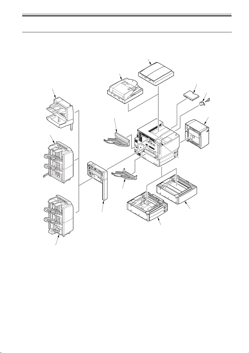
1.1 System Construction
1.1.1 System Configuration with Pickup/Delivery Accessories [USA]
[8]
[7]
Chapter 1
[1]
[5]
[2]
[6]
[4]
[13]
[3]
[9]
[14]
[10]
[11]
[12]
F-1-1
[1] Finisher-X1 [8] Platen Cover + Reader Unit (standard)
[2] Saddle Finisher-W2 [9] Document Tray-J1 (standard)
[3] Finisher-W1
[10] Paper Deck-Y1
[4] Puncher Unit-AH1 [11] Card Reader-D1
[5] Copy Tray-N1
[12] Plain Pedestal-E1
[6] Copy Tray-M1 [13] Cassette Feeding Unit-Z1
[7] DADF-M1 + Reader Unit (standard) [14] Key Switch Unit-A2
1-1
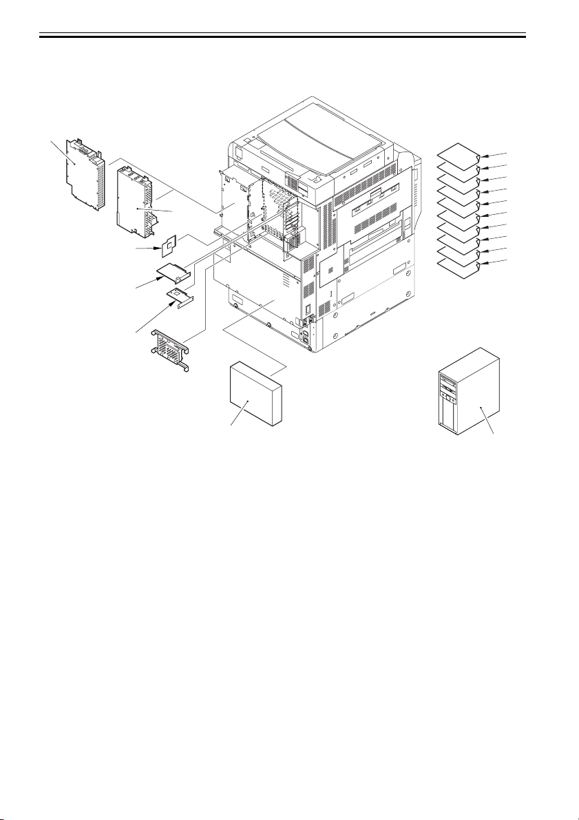
Chapter 1
1.1.2 System Configuration with Printing/Transmission Accessories [USA]
[2]
[1]
[3]
[4]
[5]
[8]
[9]
[10]
[11]
[12]
[13]
[14]
[15]
[16]
[17]
1-2
[6]
F-1-2
[1] Super G3 FAX Board-V1
[2] Super G3 Multi-Line FAX Board-H1
[3] Main Controler Borad (Sub RB-A)
[4] Voice Guidance Kit-A2
[5] Security Expansion Board-E1
[6] imagePASS-H1
[7] ColorPASS-GX100
[8] Color UFR II/PCL Printer Kit-N1 (licence*)
[9] Color PS Printer Kit-N1 (licence)
[10] Barcode Printing Kit-A1
[11] Universal Send PDF Advanced Feature Set-A1 (licence)
[12] Universal Send PDF Security Feature Set-A1 (licence)
[13] Digital User Signature PDF Kit-A1 (licence)
[14] Web Access Software-E1 (licence)
[15] Secure Watermark-A1 (licence)
[7]

[16] Encrypted Secure Print Software-C1 (licence)
[17] Remote Operator's Software Kit-A2 (licence)
*: Need [4] at the same time.
1.1.3 Functions of Printing/Transmission Accessories
Transmitting --> - Canon Color Universal Send Kit
- iR512MB Expansion RAM
Searchable PDF --> - Universal Send Searchable PDF Kit
Faxing --> - Super G3 Fax Board
- Super G3 Multi-Line FAX Board
- iR512MB Expansion RAM
UFR II/PCL Printing --> - Color UFR II/PCL Printer Kit
- iR512MB Expansion RAM
PS Printing --> - Color PS Printer Kit
- Color PCL/PS Printer Kit
- Color UFR II/PCL Printer Kit
- Color UFR II Printer Kit
- iR512MB Expansion RAM
PS Printing Server --> - Color Network Printer Unit
--> - imagePASS
- iR512MB Expansion RAM
PDF/TIFF/JPEG Direct Printing --> - Direct Printing Kit
- Color UFR II/PCL/PS Printer Kit
- Color UFR II/PCL Printer Kit
- Color UFR II Printer Kit
- iR512MB Expansion RAM
Chapter 1
1.1.4 Overview of Printing/Transmitting Accessories
The following gives an outline of individual accessories; for details, see the descriptions found in subsequent
chapters:
- Color UFR II Printer Kit
Adds GDI-UFR II printing functions and scanning functions associated with ScanGear.
The base kit for Color PCL/PS Printer Kit, Color PS Printer Kit, and Direct Printing Kit.
- Color UFR II/PCL Printer Kit
Adds GDI-UFR II printing functions, PCL printing functions, and scanning functions associated with
ScanGear.
- Color UFR II/PCL/PS Printer Kit
Adds GDI-UFR II printing functions, PCL printing functions, PS printing functions, and scanning functions
associated with ScanGear.
- Color PCL/PS Printer Kit
Adds PCL printing functions and PS printing functions.
Requires a Color UFR II Printer Kit.
1-3

Chapter 1
- Color PS Printer Kit
Adds PS printing functions.
Requires a Color UFR II Printer Kit or Color UFR II/PCL Printer Kit.
- Direct Printing Kit
Adds direct printing function to print PDF and TIFF/JPEG images through remote UI.
Requires a Color UFR II Printer Kit, Color UFR II/PCL Printer Kit, or Color UFR II/PCL/PS Printer Kit.
- Color Network Printer Unit
Print control server with PostScript3 software by Adobe Systems Inc. installed.
Cannot use simultaneously color UFR II Printer Kit, Color UFR II/PCL Printer Kit, Color UFR II/PCL/PS
Printer Kit, Color PCL/PS Printer Kit, Color PS Printer Kit, and Direct Printing Kit.
- iR512MB Expansion RAM
Adds to the installed memory (512MB).
Required when MEAP functions are added.
- Super G3 Fax Board
Adds G3 fax functions. In G3 FAX, the document created by an application can be faxed directly from PC
via network.
Cannot use simultaneously with multi-line Fax board.
- Super G3 Multi-Line Fax Board
In addition to the functions of super G3 Multi-Line FAX Board, adds two-line faxing function
Cannot use simultaneously with Super G3 Fax board.
- Canon Color Universal Send Kit
Adds the function of sending the read-in document as E-mail or I-fax document, and of storing them into file
server and box.
- Encrypted PDF Extension Kit
Adds function of setting password for PDF created by this product and encrypting it.
Requires a Canon Color Universal Send Kit.
- Universal Send Searchable PDF Kit
Perform the OCR (optical character reader) processing for the document scanned by this machine and add
the function to generate text search-capable PDF (searchable PDF).
Requires a Canon Color Universal Send Kit.
1-4
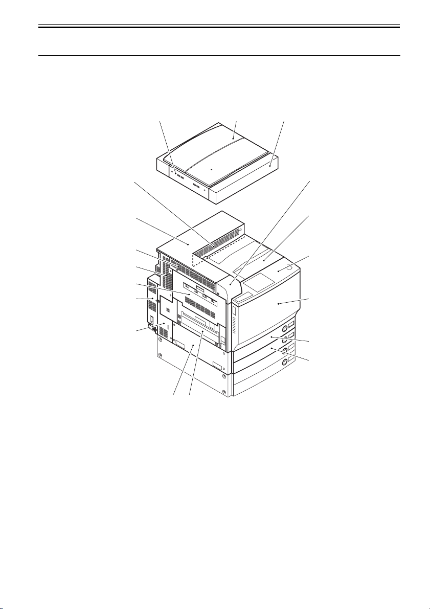
1.2 Product Specifications
4]
5]
6]
7]
8]
9]
1.2.1 Names of Parts
1.2.1.1 External View
[1] [2] [3]
Chapter 1
[18]
[17]
[16]
[15]
[14]
[13]
[12]
[10][11]
F-1-3
[1] Reader left cover [10] Fixing feeding unit cover
[2] Copyboard cover [11] Lower left cover
[3] Reader front cover [12] Rear left cover (lower)
[4] Card reader cover [13] Left rear cover (lower)
[5] Center Delivery tray [14] Delivery vertical path cover
[6] Control panel [15] Rear left cover (upper)
[7] Front cover [16] Upper left cover
[8] Cassette 1 [17] Upper cover
[9] Cassette 2 [18] Inner upper cover
[
[
[
[
[
[
1-5
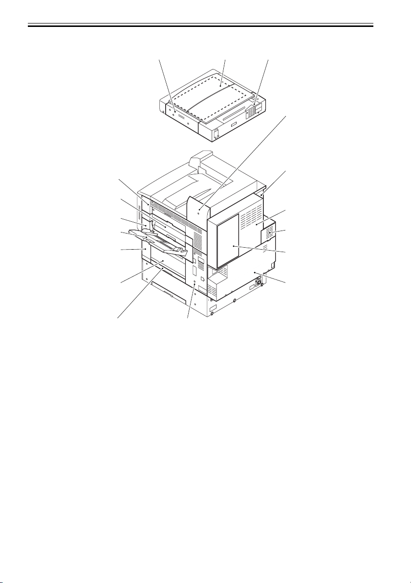
Chapter 1
4]
5]
6]
7]
8]
9]
[1] [2] [3]
[
[17]
[16]
[15]
[14]
[13]
[12]
[10][11]
F-1-4
[1] Reader right cover [10] Rear right cover
[2] Copyboard glass [11] Pick-up vertical path lower cover
[3] Reader rear cover [12] Pick-up vertical path cover
[4] Reader joint cover [13] Front right cover
[5] Left rear cover (upper) [14] Manual feed pick-up tray
[6] Upper rear cover [15] Manual feed pick-up unit cover
[7] Rear fan cover [16] Middle right cover
[8] Shield cover [17] Upper right cover
[9] Lower rear cover
[
[
[
[
[
1-6
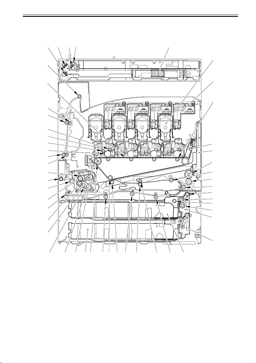
1.2.1.2 Cross Section
[1] [2] [3] [4] [5]
Chapter 1
[50]
[49]
[48]
[47]
[46]
[45]
[44]
[43]
[42]
[41]
[40]
[39]
[38]
[37]
[36]
[35]
[6]
[7]
[8]
[9]
[10]
[11]
[12]
[13]
[14]
[15]
[16]
[17]
[18]
[19]
[34]
[21][22][23][24][25][26][27][28][29][30][31][32][33]
F-1-5
[1] No. 3 mirror [26] Secondary transfer external roller
[2] No. 2 mirror [27] Secondary transfer inside roller
[3] No. 1 mirror [28] Duplex feed roller 2
[4] Scanning lamp [29] Intermediate transfer belt tension roller
[5] CCD unit [30] Cassette 2
[6] Toner cartridge [31] Intermediate transfer belt cleaner unit
[7] Laser unit [32] Pressure belt tension roller
[8] Primary transfer roller [33] Pressure belt
[20]
1-7
 Loading...