

Canon imageRUNNER ADVANCEC3530 Series Troubleshooting Manual

Trouble Shooting Guide
imageRUNNER ADVANCE
C3530 Series
September, 2017
OIP Field Quality Assurance Div.

New Arrival Information
[Regarding Troubleshooting Guide]
Please be advised of the release of Troubleshooting Guide for imagaRUNNER ADVANCE C3530 Series.
Troubleshooting Guide is a booklet compiled from FAQs issued by Canon Inc.
[Additional case(s)]
There is no additional case at September, 2017.

Contents
Image Faults......................................................................................................... 1
Poor image which is round weak density / poor image which is weak density band, they occur
due to using left paper in a low-humidity environment.....................................................................1
Image blanking on the trailing edge of the second side of sheet with heavy paper under a low
humidity environment.......................................................................................................................3
Image blanking on the leading edge of sheet with heavy paper under a low temperature
environment.....................................................................................................................................5
Malfunction........................................................................................................... 7
Measures when paper is not stapled (corner/double) after installation (Inner Finisher-G1/H1/K1).....7
Noise/Odor............................................................................................................9
Noise (an abnormal noise from meshing failure of tooth)/ toner soiling inside the machine /
stained images due to disengagement between gears in the waste toner drive assembly............. 9
Error Code.......................................................................................................... 11
Measure against E674-0100............................................................................................................. 11
i
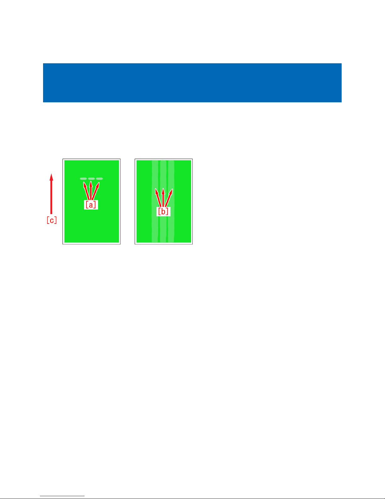
Image Faults
Copier Color | iR-ADV C3530/C3525/C3520 Series |
Poor image which is round weak density / poor image which is
weak density band, they occur due to using left paper in a lowhumidity environment.
[Symptom]
Poor image which is round weak density [a] or poor image which is weak density band [b] may occur when a high density image
is printed out with the paper which is left outside of the machine in a low-humidity environment. Only one poor image occurs at
times, some poor images occur at other times.
The arrow [c] indicates the feed direction.
[Cause]
Electric resistance of the paper is higher because the paper is dehydrated by leaving in a low-humidity environment.
Electric resistance at the timing of the passing of 2nd side of 2-sided print is higher because the moisture of the paper is lost
when the 1st side is fixed.
Electric resistance of feeding roller is higher because moisture content in the air is low under the low-humidity environment.
Transferring of a high density image needs higher secondary transfer voltage than that of a low density image.
When the total electric resistance of the paper and the roller is higher than expected at the Secondary transfer Assembly, the
above symptom occurs because of insufficient secondary transfer voltage.
Especially when the 2nd side has high density image, the symptom is easy to occur.
[Service work]
[Reference]
Improving a state of preservation of paper may be effective in resolving a trouble in some cases.
Explain to a customer that unused or remaining paper should be stored by being covered with wrapping paper in a place avoiding
direct sunlight.
Choose and perform between the below a) and b).
a) Increase the secondary transfer voltage in User mode.
a-1) Log in to the User mode with "System administration mode".
a-2) Go to Select Settings/Registration > Personal Settings ( Device Settings ) > Preferences > Paper Settings > Paper Type
Management Settings , select an appropriate paper type from among the list, press "Duplicate" button and then "OK" button.
a-3) Enter any name as the duplicated paper type and press "OK" button.
a-4) Select the paper type duplicated in the step a-3) and press "Details/Edit".
a-5) Change the setting value by pressing " Change " button of "Adj. secondary transfer voltage " .
- When the symptom occurs on the 1st side o f 1-sided print or 2-sided print, change the setting value of "Front side" to "3" and
then press "OK".
- When the symptom occurs on the 2nd side of 2-sided print, change the setting value of "Back side" to "3" and then press "OK".
The range of setting is from "-80" to "80" ("0" by default).
As the setting value is changed by 1, the secondary transfer voltage changes by 50V.
1
a-6) Set media as duplicated paper type and then output the image having shown the symptom and check
that the symptom does not occur.
If the symptom does not improve sufficiently, reduce the setting value in the step a-5) by "3" at a time up to "18" until the symptom
improves enough.
[Caution] Poor transfer may occur due to too high secondary transfer voltage if the setting value is changed.
If the symptom does not improve, look into other causes.
b) Increase the secondary transfer voltage in Service mode.
[Note] When the above Service Mode is not displayed, install the latest system software.
The secondary transfer voltage setting works only when all the conditions (mode/environment/paper type) registered beforehand
are met.
16 different patterns can be set from "TR-DUP1" to "TR-DUP16".
The below procedure is to set "TR-DUP1".
b-1) Go to Service mode (Level 2) > Mode List > COPIER > Adjust > HV-TR > and change the setting value of "TR-DUP1".
- If the symptom occurs in 1-sided print mode, check if the value is "11".
- If the symptom occurs on the 2nd side in auto 2-sided mode, change the value to "12".
- If the symptom occurs on the 2nd side in multi-purpose tray 2-sided mode, change the value to "13".
The range of setting is from "11" to "43" ("11" by default).
b-2) Go to Service mode (Level 2) > Mode List > COPIER > Adjust > HV-TR > and confirm if the setting value of "TR-ENV1" is
set to "1".
The range of setting is from "1" to "3" ("1" by default).
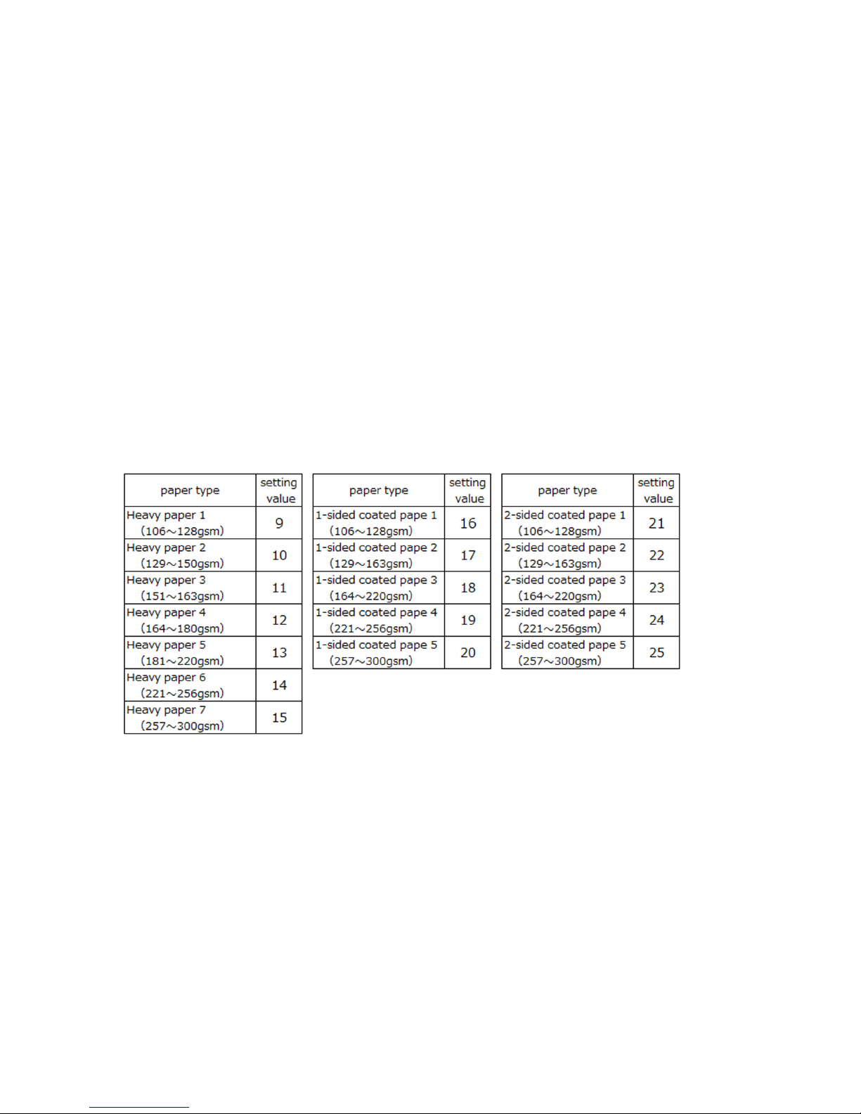
b-3) Choose the appropriate value from among the below tables according to the used paper type and apply it to the setting value
of Service mode (Level 2) > Mode List > COPIER > Adjust > HV-TR > "TR-PPR1".
The range of setting is from "1" to "33" ("1" by default).
b-4) Go to Service mode (Level 2) > Mode List > COPIER > Adjust > HV-TR > and change the setting value of "TR-VL1" to "5".
The range of setting is from "-128" to "+127" ("0" by default).
As the setting value is changed by 1, the secondary transfer voltage changes by 30V.
b-5) Output the image having shown the symptom, and check that the symptom does not occur.
If the symptom does not improve sufficiently, reduce the setting value in the step b-4) by "5" at a time up to "30" until the symptom
improves enough.
[Caution] Poor transfer may occur due to too high secondary transfer voltage if the setting value is changed.
If the symptom does not improve, look into other causes.
2
 Loading...