


Troubleshooting Guide
imagePRESS C850 Series
March, 2018
Canon U.S.A., Inc.

New Arrival Information
[Regarding Troubleshooting Guide]
Please be advised of the release of Troubleshooting Guide for imagePRESS C850 Series.
Troubleshooting Guide is a booklet compiled from FAQs issued by Canon Inc.
[Additional case(s)]
•
1008 Jam Code due to nip failure of post card feeding rollers (Finisher)

Contents
Image Faults......................................................................................................... 2
Optimization of fixing pressure and fixing temperature when envelops are fed
..................................2
Non-glossy streaks due to the peeled off tape on the separation plate.............................................. 5
From 1.6mm to 1.7mm pitch uneven density occurring when coated sheets whose basis
weight is 200gsm or more are continuously output....................................................................... 14
Marks on image caused by friction due to mini gripper edge (Perfect Binder- B1/D1/E1)................ 16
Soiled image (Black dots) due to toner unable to be collected by a scraper.....................................22
Malfunction......................................................................................................... 24
Point to note when replacing the transfer cleaning unit.....................................................................24
Safety cover coming off of Tray 1 due to the safety cover being pressed hard to the rear side
or downward (Saddle/Staple/Booklet/Finisher)..............................................................................26
Jam (Main Unit).................................................................................................. 41
Measures when the display of jam 011B/0118/010F/021B/0218/020F/0A1B/0A18/0A0F
cannot be canceled (POD Deck Lite-B1/C1/Paper Deck Unit-E1/F1)........................................... 41
Jam (Delivery options).......................................................................................44
1004 Jam Code or folded corner on printed out paper due to positional displacement of
support (Staple/Saddle/Booklet/Finisher)...................................................................................... 44
110F Jam code due to meshing failure of the timing belt (Staple-W1/Booklet-W1/Saddle-AN2/
Finisher-AN1).................................................................................................................................46
1008 Jam Code due to nip failure of post card feeding rollers (Finisher) .........................................48
Error Code.......................................................................................................... 53
E750-0003 error may occur, when install the Auto Gradation Sensor-A1.........................................53
Points to note when replacing the lower belt assembly.....................................................................54
Points to note when replacing the fixing belt unit.............................................................................. 56
Points to note when replacing timing belt set of the operation tray assembly (Staple/Booklet
Finisher-C1/J1/M1/T1/U1)............................................................................................................. 58
E003-0002 due to poor fitting of the claws of the paper cooling lower ducts.................................... 65
E568-8002/Shaved gear tooth due to overloading with friction from sliding while the
estrangement rack is moving (Staple-Q1/W1/Booklet-Q1/W1/Saddle-AM2/AN2/Finisher-
AM1/AN1)...................................................................................................................................... 68
Specifications-Related.......................................................................................72
The breakage of copy tray hooks due to an overloading of output paper (Copy Tray-
P1/R1/R2/Output Tray-A1 )........................................................................................................... 72
Notice when replacing the fixing gears..............................................................................................74
i

Image Faults
Optimization of fixing pressure and fixing temperature when
envelops are fed
[Symptom]
When envelops pass the fixing assembly, the load is centralized on the overlapping points [a] on the reverse side of envelop.
Therefore an image having partial white spots may be output due to the occurrence of worn-out fixing belt surface or shaved
rubber of fixing roller surface. If the fixing pressure is greater, the overlapping points [a] may make impresses [b] on the front of
envelop depending of the type of envelop.
[Service work]
As
the measure of the above-mentioned symptoms, MN-CONT is graded up to v30.52 and D-CON is graded up to v30.31 for the
following 2 controls.
A) Optimization and segmentation of fixing pressure and fixing temperature for envelops.
B) Increase of changing range for fixing pressure adjusted values of envelops.
A) Optimization and segmentation of fixing pressure and fixing temperature for envelops.
The default value for fixing pressure is decreased and the default value for fixing temperature is increased. The paper weight is
classified into 6 ranges and each range has its specified default values for fixing pressure and fixing temperature.
This
Optimization and segmentation reduce the abrasions of fixing belt surface or fixing roller surface and then the image having
partial white spots will rarely occur.
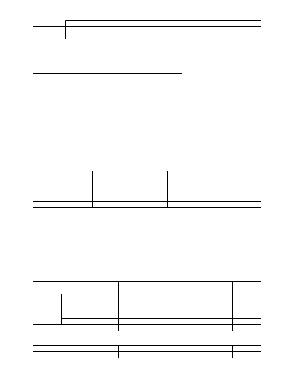
[Reference] The following table shows the previous fixing pressure and fixing temperature when passing envelopes.
Width of envelop/Paper weight 181 to 220
Less than 220mm 870 pls
180℃
More than 221mm 1170 pls
180℃
• The unit of paper weight is g/m2.
• [pls]
in the table means the unit of fixing pressure. The numeric value means the number of pulse which drives the pressure
motor from its home position. The bigger the numeric value is, the greater the pressure is.
The following table is for optimized and segmentalized new fixing pressure and fixing temperature.
Classification 1 2 3 4 (Default) 5 6
Width of envelop/
Paper weight
106 to 128 129 to 150 151 to 180 181 to 220 221 to 256 257 to 300
Less than 130mm 870 pls 600 pls 400 pls 400 pls 200 pls 200 pls
180℃ 190℃ 190℃ 190℃ 195℃ 195℃
131 to 180mm 870 pls 600 pls 600 pls 600 pls 400 pls 200 pls
180℃ 190℃ 190℃ 190℃ 195℃ 195℃
181 to 220mm 1170 pls 870 pls 600 pls 600pls 400 pls 200 pls
2
181 to 220mm
180℃ 190℃ 190℃ 190℃ 195℃ 195℃
More than 221mm 1170 pls 870 pls 600 pls 600 pls 400 pls 200 pls
180℃ 190℃ 190℃ 190℃ 195℃ 195℃
• Classification 4 indicates the default value in the new fixing pressure and fixing temperature table.
• The
paper weight range which does not meet the specification, from 160 to 180 or from 221 to 300, can be set. However the
picking, feeding and the image quality are not given guarantee.
B) Increase of changing range for fixing pressure adjusted value of envelops.
The changing range for the adjusted value table which is selected with User Mode [Adjust fixing pressure] is increased to make
the impress of envelop difficult to appear.
As the default value is changed from [-1] to [-3], the state of the impress will be improved gradually. On the other hand, if the
image has generous amount of toner deposit, it leads poor fixing capacity by changing the adjusted values.
Adjust Fixing Pressure Recommended conditions of use Degree of improvement for the impress
-1 Image with small amount of toner deposit.
(Image with small amount of solid parts)
Slightly improved
-2 Image with small amount of toner deposit.
(Image with small amount of solid parts)
Almost no impress
-3 Text image No impress
[Reference]
The
following sample indicates the case of adjusted values of fixing pressure for an envelope whose width is 130 mm or less and
the weight is from 181 to 220 (g/m2).
[A] line in the table shows previous adjusted values and [B] line indicates new adjusted values.
The changing range of new adjusted values is increased compared with the changing range of previous adjusted values.
Adjust Fixing Pressure [A] [B]
1 940pls 500pls
0(Default) 870pls 400pls
-1 800pls 100pls
-2 730pls -100pls
-3 660pls -200pls
The following new table of fixing pressure and fixing temperature for envelopes also includes the above-mentioned 2 new controls.
•
Classification 4 in the table indicates the default value.
• The unit of paper weight is g/m2.
• P rows in the table show the setting values of fixing pressure. The numeric value means the number of pulse which drives
the pressure motor from its home position. The bigger the numeric value is, the greater the pressure is.
• Setting table of fixing pressure can be selected with User Mode [Adjust fixing pressure] (+1,0,-1,-2,-3). The default value is
[0].
• The fixing temperature can be fine-tuned with User Mode [Adjust Gloss/Fine Black]. Adjustable range: -2,-1, 0, +1, +2,
Changing range: 5 degrees C, High end: 200 degrees C. (When it is over 200 degrees C, it should be taken as 200 degrees
C)
- Width of envelop : Less than 130mm
Classification 1 2 3 4 5 6
Paper weight 106 to 128 129 to 150 151 to 180 181 to 220 221 to 256 257 to 300
P
1 940 700 500 500 300 300
0 870 600 400 400 200 200
-1 800 300 100 100 -100 -100
-2 730 100 -100 -100 -200 -200
-3 660 -100 -200 -200 -300 -300
Fixing temperature 180℃ 190℃ 190℃ 190℃ 195℃ 195℃
- Width of envelop : 131 to 180mm
Classification 1 2 3 4 5 6
Paper weight 106 to 128 129 to 150 151 to 180 181 to 220 221 to 256 257 to 300
3
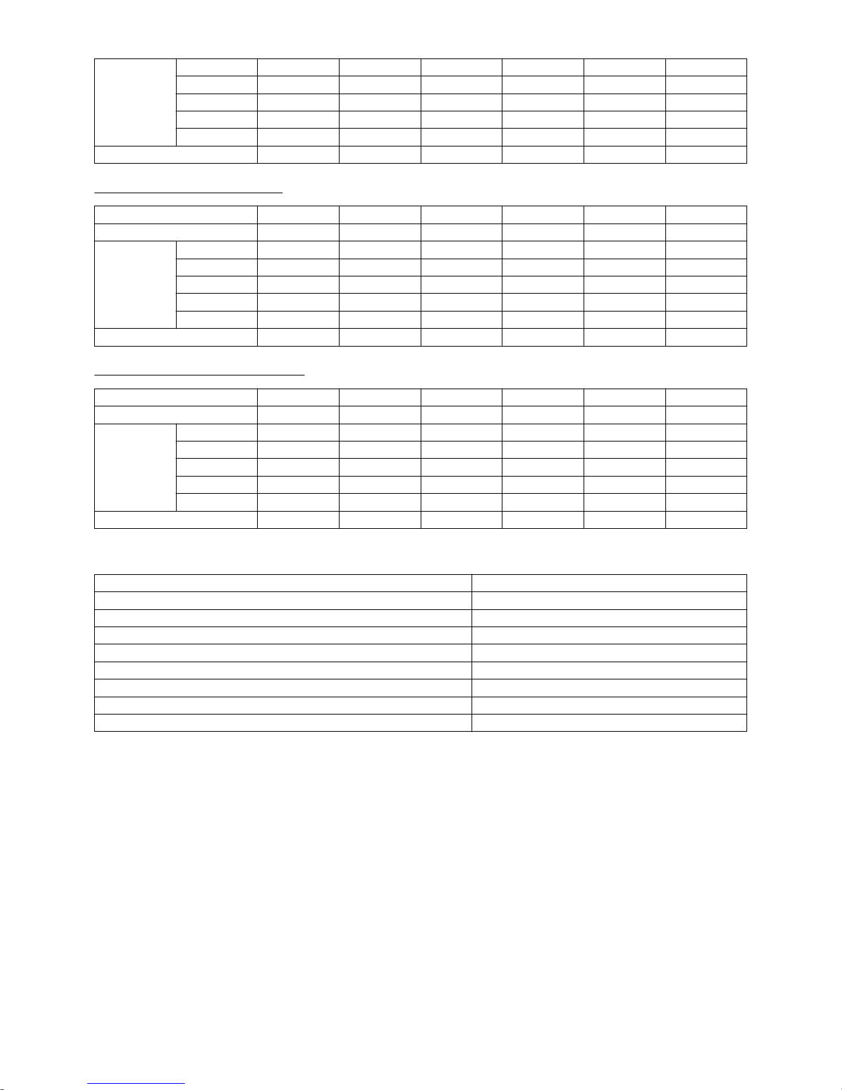
P
1 940 700 700 700 500 300
0 870 600 600 600 400 200
-1 800 300 300 300 100 -100
-2 730 100 100 100 -100 -200
-3 660 -100 -100 -100 -200 -300
Fixing temperature 180℃ 190℃ 190℃ 190℃ 195℃ 195℃
- Width of envelop : 181 to 220mm
Classification 1 2 3 4 5 6
Paper weight 106 to 128 129 to 150 151 to 180 181 to 220 221 to 256 257 to 300
P
1 1240 940 700 700 500 300
0 1170 870 600 600 400 200
-1 1100 800 300 300 100 -100
-2 1030 730 100 100 -100 -200
-3 960 660 -100 -100 -200 -300
Fixing temperature 180℃ 190℃ 190℃ 190℃ 195℃ 195℃
- Width of envelop : More than 221mm
Classification 1 2 3 4 5 6
Paper weight 106 to 128 129 to 150 151 to 180 181 to 220 221 to 256 257 to 300
P
1 1240 940 700 700 500 300
0 1170 870 600 600 400 200
-1 1100 800 300 300 100 -100
-2 1030 730 100 100 -100 -200
-3 960 660 -100 -100 -200 -300
Fixing temperature 180℃ 190℃ 190℃ 190℃ 195℃ 195℃
[Countermeasure cut-in serial numbers in factory]
Model Serial number
imagePRESS C800 Series 208V US/CA/LTN UME02254
imagePRESS C800 Series 230V EUR/AU/SG/IN/HK/LTN/KR UMF00648
imagePRESS C800 Series 230V CN/HK/TW UMG00509
imagePRESS C700 Series 230V CN/HK/TW UMH00533
imagePRESS C700 208V US WHV02264
imagePRESS C600i 230V EU UML00764
imagePRESS C600 220V CN UMK00531
imagePRESS C60 208V UL UMJ00702
4

Non-glossy streaks due to the peeled off tape on the separation
plate
[Symptom]
On the main body whose Countermeasure Cut-in Serial Numbers in Factory is earlier than the following number, non-glossy
streaks [a] image may occur with high gloss media or heavy media (200g or more).
The arrow indicates the paper feed direction.
[Cause]
The separation plate [1] in the fixing assembly [A] comes in thick and thin types. The tape affixed to the thicker separation plate
[1] comes off [a] from scuffing, then the fed paper comes in contact with the peeled off tape and leads to the above mentioned
symptom.
The arrow [b] indicates the paper feeding path.
[Service work]
As a countermeasure against the aforementioned symptom, replace the separation plate with the thinner type that reduces
scuffing of the tape even when a high gloss or heavy media is passed through.
To make this feasible, newly assign the fixing separation unit with the thinner separation plate, inner paper delivery assembly
and fixing base assembly as service parts respectively. The other type with thicker separation plate is also going to be newly
assigned as well. As to the newly assigned new type inner paper delivery assembly and the fixing base assembly, their fixing
separation units are removable. The fixing separation units of the old types are not removable.
If
the shape of the inner paper delivery assembly is as shown in the photo [A], replacing the fixing separation unit only is possible.
The photo [B] shows the shape of the old type inner paper delivery assembly.
5

When the above mentioned symptom has occurred, follow the procedure below, however either of the thick type fixing separation
unit and thin type fixing separation unit should be chosen according to the conditions.
Check to see if the inner paper delivery assembly is the new type or the previous type, if it is the new type follow the procedure
A, and if it is the previous type, then follow B.
A). Handling by replacing the fixing separation unit
Prepare a fixing separation unit (thin type)(FM1-R470-000).
1) Refer to the service manual to take out the fixing assembly.
2) Hold the grip [1] and open the inner paper delivery assembly [2].
3) Remove the duct [1].
- Stepped screw [2] 2 pcs
4) Remove the spring mount pin [1] and the torsion spring [2] on the rear side of the inner paper delivery assembly.
- Screw [3] 1 pcs
5) Remove the spring [1] on the front side of the inner paper delivery assembly.
6

6) Remove the separation plate [1] while lifting the rear side.
7) Put the mounting hole [1] on the front side of the new separation plate prepared in the positioning pin [A] and fit the screw [2]
on the rear side of the separation plate in the cut out [B].
8) Put the straight end [1] of the torsion spring in the notch [A] on the separation plate and mount the spring [2] on the positioning
pin [B].
[Reference] The torsion springs for the front side [A] and rear side[B] have different shapes.
9) Put the bent end [1] of the torsion spring in the boss [A] on the metal plate.
7

[Note] After mounting the torsion spring, confirm if the straight end of the spring [1] has not come off the notch [A] on the separation
plate.
10) Assemble the spring mount pin [1] and the torsion spring [2].
11) Hook the straight end of the torsion spring [1] on the notch [A] on the separation plate and insert the spring mount pin [2] into
the hole [B] on the metal plate.
12) Hook the bent end [1] of the torsion spring on the boss [A] on the metal plate and mount the positioning pin [2].
- Screw [3] 1 pcs
8

[Note] After mounting the torsion spring, confirm if the straight end of the spring [1] has not come off the notch [A] on the separation
plate.
13) Mount the duct [1].
- Stepped screw [2] 2 pcs
14) Close the inner paper delivery assembly and install the fixing assembly.
15) Take some prints and check the image. If the image appears normal, the work is finished.
16) A streaks with 174mm regular intervals may rarely occur. (The arrow [a] indicates the paper feed direction.)
In that case, from User mode go to Settings/Registration > Preferences > Paper Settings > Paper Type Management
Settings,select the paper type with which the streaks occurs, press the change button of "Adjust Fixing Speed" in [Details/Edit]
to adjust the fixing speed towards the positive direction.
9

If the streaks appear on images even after adjusting the fixing speed, replace the fixing separation unit with the thick type (FM1R469-000).
B). Handling by replacing the inner paper delivery assembly
Newly assign the spring set plate (FL1-3976-000) to be used to mount the spring on the rear side of the inner paper delivery
assembly. Prepare the said spring set plate and the inner paper delivery assembly (thin type) (FM1-R600-000).
1) Refer to the service manual to take out the fixing assembly.
2) Remove the 2 screws [1] and the duct.
3) Remove the e-ring [1] that is securing the inner paper delivery assembly on the rear side of the fixing base assembly.
4) Remove the 1 screw [1] that is securing the inner paper delivery assembly on the front side of the fixing base assembly.
5) Draw out the inner paper delivery assembly from the front side. To do this, remove the springs [1] attached to the both sides
of the inner paper delivery assembly from the bosses that is supporting point. Also disconnect the cable connector [2].
10

6) Reattach the springs attached to the both side of the removed inner paper delivery assembly to the new type inner paper
delivery assembly.
[Reference]
- Apply grease (SE1107) around the spring mount hole.
- The front/rear mounting positions and orientations of the springs are specified respectively. Attach the springs as their looped
ends [a] come outside.
The
photo [A] shows the spring attached to the rear side of the inner paper delivery assembly and [B], the spring attached to the
front side of the inner paper delivery assembly.
7) Insert the new type inner paper delivery assembly from its rear side and install to the fixing base assembly. At this moment,
the spring on the rear side is not yet put around the boss.
8)
Putting the looped portion of the spring on the front side in the boss, secure the front side of the inner paper delivery assembly
with the 1 screw [1] removed in the step 4).
9) Secure the rear side of the inner paper delivery assembly with the 1 e-ring (XD9-0135-000).
11

10) Reconnect the connector disconnected in the step 5).
11) Fit the boss [b] at the tip of the spring set plate (FL1-3976-000) into the looped portion [a] at the center of the spring on the
rear side of the inner paper delivery assembly.
12) Put the looped end of the spring on the rear side of the inner paper delivery assembly in the boss on the fixing base assembly.
[Note] To attach the spring, put the looped end [a] in the boss [b]. Do not put the looped portion at the center [c] in the boss [b].
The photo [A] indicates the proper way to attach the spring and [B], an erroneous way to attach the spring.
13) Reassemble the parts in reverse order from the step 2).
14) Take some prints and check the image. If the image appears normal, the work is finished.
15) Streaks at 174mm intervals occur infrequently. In that case, perform the work in the step 16) of the aforementioned procedure
"A) Handling by replacing the fixing separation unit".
[Reference]
Procedure to replace the fixing base assembly
Refer to the service manual for replacing the fixing base assembly.
• FIXING BASE ASSEMBLY ( Thick type) ( FM0-1373-010 )
• FIXING BASE ASSEMBLY ( Thin type ) ( FM1-P430-000 )
[Service parts]
No. Part Number Description Q'ty Fig.No.
1 Old FM0-1373-000 FIXING BASE ASSEMBLY 1 -> 0 812
New
FM1-P430-000
FIXING BASE ASSEMBLY
(Thin type)
0 -> 1
2 Old FM0-1373-000 FIXING BASE ASSEMBLY 1 -> 0 812
12
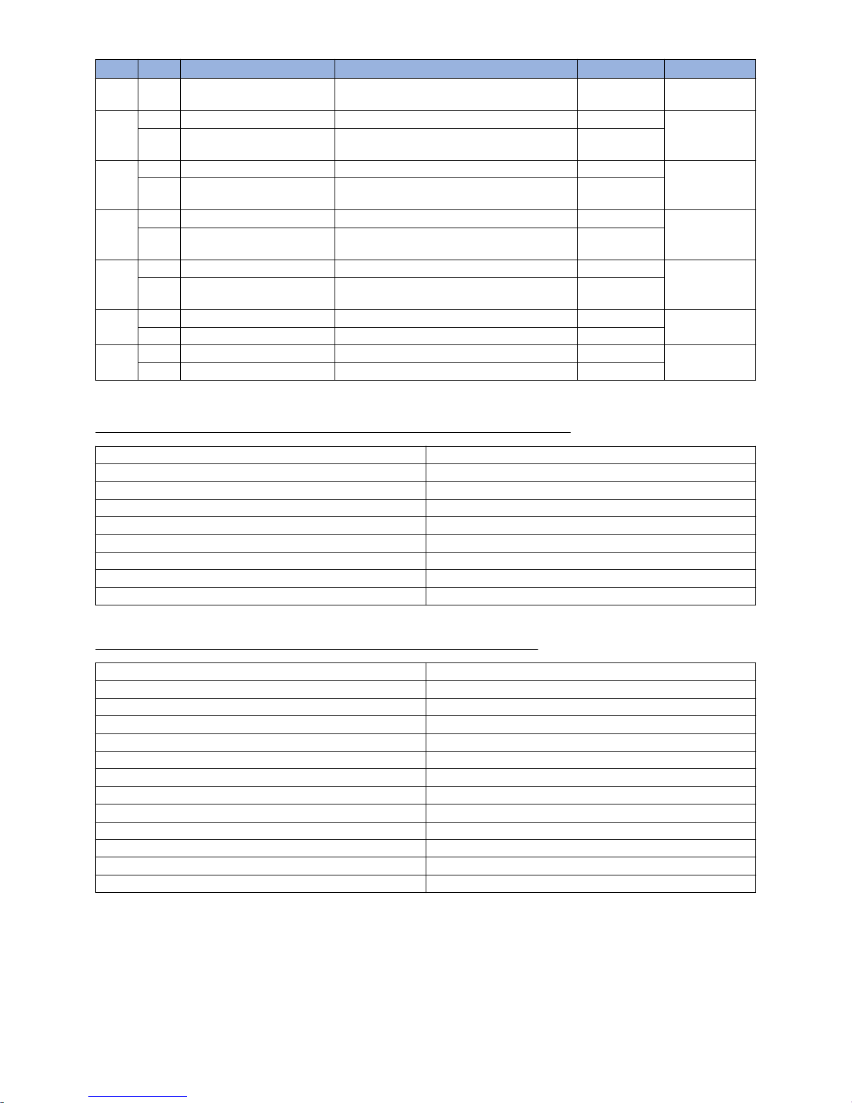
No. Part Number Description Q'ty Fig.No.
2
New
812
FM0-1373-010
FIXING BASE ASSEMBLY
(Thick type)
0 -> 1
3 Old 812
New
FM1-R599-000
INNER PAPER DELIVERY ASSEMBLY
(Thick type)
0 -> 1
4 Old 812
New
FM1-R600-000
INNER PAPER DELIVERY ASSEMBLY
(Thin type)
0 -> 1
5 Old 812
New
FM1-R469-000
FIXING SEPARATION UNIT
(Thick type)
0 -> 1
6 Old 812
New
FM1-R470-000
FIXING SEPARATION UNIT
(Thin type)
0 -> 1
7 Old
New FL1-3976-000 PLATE, SPRING SET 0 -> 1
8 Old FY9-6036-000 LUBE, SE1107 GREASE 0 -> 1
New
[Countermeasure cut-in serial numbers in factory]
- Switch the separation plate in the fixing separation unit from the thick type to the thin type.
Model Serial number
imagePRESS C800 Series UL 208V UME02480
imagePRESS C60 UL 208V UMJ00761
imagePRESS C700 US 208V WHV02269
imagePRESS C800 Series EU 230V Not applicable
imagePRESS C800 CN 220V Not applicable
imagePRESS C700 CN 220V Not applicable
imagePRESS C600 CN 220V Not applicable
imagePRESS C600i EU 230V Not applicable
- Change the component formation so that the fixing separation unit can be removed.
Model Serial number
imagePRESS C850 Series UL 208V WJC00500
imagePRESS C850 Series EU/O 230V WJD00500
imagePRESS C850 CN 220V WJE00500
imagePRESS C650i US 208V WJJ00500
imagePRESS C800 Series UL 208V UME02277
imagePRESS C800 Series EU/O 230V UMF00616
imagePRESS C800 CN 220V UMG00509
imagePRESS C700 CN 220V UMH00533
imagePRESS C60 UL 208V UMJ00697
imagePRESS C600 CN 220V UMK00531
imagePRESS C600i EU 230V UML00644
imagePRESS C700 US 208V WHV02269
13

From 1.6mm to 1.7mm pitch uneven density occurring when
coated sheets whose basis weight is 200gsm or more are
continuously output
[Symptom]
From
1.6mm to 1.7mm pitch uneven density [a] may appear in main scanning direction on the second sheet or later when coated
sheets whose basis weight is 200gsm or more are continuously output. The symptom is prominently seen on a black halftone
image. The arrow [b] indicates the direction of feeding.
[Cause]
Because
the paper feeding speed of fixing assembly is faster than the speed of secondary transfer unit, the media will be pulled
between the secondary transfer unit and the fixing assembly. Therefore, the vibration of fixing idler gear is transferred to the
scanner and that results in the above symptom.
[Service work]
When the above symptom occurs, adjust the fixing speed to minus side for every sheet in the management setting for media type
in user mode.
1) Have the customer log in from System Management Mode in user mode.
2) Go to Select Settings/Registration > Preferences > Paper Settings > Paper Type Management Settings, select an appropriate
paper type from among the list, press "Duplicate" button and then "OK" button.
3) Enter any name as the duplicated paper type and press "OK" button.
4) Select the paper type copied in the step 3) and then press "Details/Edit" button.
5) Select "Adjust Fixing Speed" and then press "Change" button.
14

[Reference] In case Adjust Fixing Speed will not be displayed on the control panel, change the setting value of Service Mode >
Mode List > COPIER > Option > DSPLY-SW > IMGC-ADJ to "1". The value is "0" by default.
6) Change the setting value to minus side and press "OK" button.
The configurable range for the value is from "-20" to "+20". (Default: 0)
7)
Select the paper type which is set from step 2) to step 6) and output the image which had the symptom to make sure that the
symptom does not occur any more.
If the symptom does not improve, then check other factors.
15

Marks on image caused by friction due to mini gripper edge
(Perfect Binder- B1/D1/E1)
[Symptom]
The marks caused by friction [A] may appear on the first and last pages of glued stacked of sheets during printing.
[Reference] This symptom remarkably occurs on glossy paper such as coated paper.
[Cause]
The
stuck of sheets loaded on the height tray assembly is fed by sub gripper assembly and then transferred to the main gripper
assembly. The marks caused by friction are put on the first and last pages of glued stacked of sheets due to the edges of round
holes [a] of mini gripper [1] being located at the upper and lower sides of main gripper assembly when transferring.
[Service work]
If
the above-mentioned symptom occurs, prepare the sheet kit (4Y8-3138-000) to affix the sheet on the mini gripper being located
on the upper and lower sides of main gripper assembly.
1) Turn off the main power of perfect binder and then unplug the power cord.
2) Remove the parts below referring Service Manual.
- Front Covers (Left/Right)
- Rear Cover
- Rear Upper Cover
- Inner Cover (Upper/Lower)
3) Turn on the right front cover switch and left front cover switch by inserting the service tool or the like.
16

4) Remove the service PCB cover.
• 1 screw
5) Turn on SW1-2 and SW2-8 on the service PCB and set the machine in service mode.
[CAUTION] To keep the machine running in service mode, be sure to do so with the trimming assembly stowed inside.
6) Plug the power cord in the wall outlet.
7) Turn on the power switch and then perform machine initialization operation.
8) Turn off the power switch.
9) Turn on SW1-1 on the service PCB and set the machine in service mode.
17

10) Turn on the power switch.
11) Turn on SW2-1 and -3 on the service PCB and then press the push switch PSW1 3 (three) times to stop the mini gripper at
the vertical position.
12) Turn off the main switch and unplug the power cord from the wall outlet.
13) Remove the filter case unit.
• 3 screws
14) Remove the glue transport stay.
• 1 screw
18

[CAUTION] When attaching the glue transport stay, hang the cut part of the stay to the projection of the glue supply entrance.
15) Stand behind the machine to face the back side and then remove screws [2] fixing the mini grippers [1].
• 2 screw
[Attention] Be careful not to drop the screws into the machine during the operation.
16) Stand in front of the machine to face the front side and then remove screws [2] fixing the mini gripper [1].
• 2 screw
[Attention] Be careful not to drop the screws into the machine during the operation.
17) Remove the screw [2] being the left side of mini gripper [1] on your left and then disconnect the fixed ground wire [3].
• 1 screw
19

18) Remove the connector [2] being the right side of mini gripper [1] on your right and then remove the screw [3] to disconnect
the ground wire [4].
• 1 screw
19) Lift up (in the direction of the black arrow) left and right mini grippers to remove the 2 (two) mini grippers from the pins [1].
The following photo shows the state that 1 (one) mini gripper [2] has been taken from the back side of machine.
20) Prepare the sheet kit (4Y8-3138-000) to affix the sheet on the mini gripper removed from the main gripper along the following
reference lines.
- Affixing reference line [a]: Affix the left edge of sheet [1] at where it is within 1mm from the edge of mini gripper.
- Affixing reference line [b]: Affix the upper edge of sheet [1] at where it is within 1mm from the upper edge of mini gripper.
Affix the sheet not to protrude from the reference lines [a] and [b].
20

21) Reassemble the parts in the reverse order from Step 13).
[Attention] Make sure that the position of unit [1] being the side of mini gripper is correct and then put the mini gripper.
Photo [A] shows upside-down position of the unit on the side of mini gripper. Photo [B] shows the correct position.
[Service parts]
No. Part Number Description Q'ty Fig.No.
1 Old P51
New 4Y8-3138-000 SHEET KIT 0 -> 1
21

Soiled image (Black dots) due to toner unable to be collected by
a scraper
[Symptom]
When printing with the machines manufactured before the following serial numbers, soiled image (black dots) [a] may occur at
the edge of papers (front or rear side) in 37mm intervals.
The arrow [b] indicates the feed direction.
[Cause]
The double-sided tape that secures the scraper [1] which collects waste toner has a shape where the edge of the glued portion
is narrower than the center of the glued portion. Thus depending on the force to affix the scraper [1] or the displacement of the
affixing position, in a high temperature/high humidity environment, the position of the edge may be displaced [b] depending on
the
force loaded in the direction of the arrow [a]. The above symptom occurs because toner cannot be collected in the area where
the sheet is displaced.
[Service work]
The developing assembly (black) is changed to the new type where the double-sided tape securing the sheet has stronger
adhesive.
- iR-ADV C9000/C7000/C9000S Series : FM4-6615-020 DEVELOPING ASSEMBLY, BK
- iR-ADV C9200/C7200 Series : FM0-2709-010 DEVELOPING ASSEMBLY, BK
- imagePRESS C800/C850 Series : FM1-C717-020 DEVELOPING ASSEMBLY, BK
[Service parts]
(iR-ADV C9000/C7000/C9000S Series)
No. Part Number Description Q'ty. Fig. No.
1
Old FM4-6615-010 DEVELOPING ASSEMBLY, BK 1->0
102
New FM4-6615-020 DEVELOPING ASSEMBLY, BK 0->1
(iR-ADV C9200/C7200 Series)
22
 Loading...