

Page 1

CR-X500 1A
CR-X500 2A
PUB. DIE-0557-000E
Remote Camera
Instruction Manual
Page 2
Important Safety and Handling Instructions
In Case of Emergency (troubleshooting under abnormal
situations)
Transportation/Installation
• Do not install the product in a location where there is the risk
of ignition or combustion.
Installing the product in a location where flammable gases
are produced or concentrated may cause ignition and
result in fire.
• Securely attach any parts to the product, firmly tightening
the necessary screws according to the instruction manual.
If the product is not firmly secured or if screws are loose,
the product may topple over or fall down, resulting in injury
and accidents.
• When installing the product in an elevated location, make
sure to take appropriate measures in advance to prevent the
equipment and parts from falling off.
Equipment falling down may cause serious injury.
Power supply
• Ensure the power cable is fully inserted into the power
outlet.
• Do not handle the power cable or plug with wet hands.
• Do not leave the product plugged in for extended periods of
time in locations exposed to high levels of dust, moisture or
oily smoke.
Doing so may cause insulation failures and even fires.
• Periodically wipe the power cable, power outlet and
terminals with a dry cloth to remove dust buildup.
• Make sure to turn off the product before connecting/
disconnecting power cables.
• Do not use excessive force on the power cable.
A damaged power cable can lead to fire or electric shock.
• DC power model only:
- Make sure to use a power cable that is suitable for the
installation conditions (authorized products, environmental
regulations) and conforms to the product's power
specifications. Using an unsuitable power cable may
cause electric shock and fire.
- Remove the screws together with the power cable.
Handling
• Do not allow liquids or foreign matter inside the unit.
• Do not expose the product to strong shocks or vibration.
Maintenance and Inspection
• Unplug the power cable from the power outlet before
cleaning it using a dry cloth.
Cleaning the power cable when the product is turned on or
using a wet cloth may cause electric shock.
• Do not use organic solvents such as alcohol, benzene or
paint thinner to clean the product.
• Do not disassemble or modify the product.
- There are exposed electrodes and gears inside the
product. Contact with such parts may cause injury or
electric shock.
- Foreign objects or dust entering into the product may
cause malfunctions.
- In surroundings exposed to high temperatures and
humidity, humid air entering inside the product may cause
malfunctions and condensation.
Transportation/Installation
• Do not install the product on an unstable surface or in
locations exposed to severe vibration.
This may cause the product to topple over or fall down,
resulting in injury.
• Do not install the product in locations directly exposed to salt
water or where corrosive gases or oily smoke are present.
Contact with such substances may corrode and degrade
the mountings, causing the product to fall down and cause
injury.
• When transporting the robotic camera head, always use two
people to lift it, firmly grabbing the handles.
Dropping the product may damage it and cause injury and
accidents.
Handling
• Make sure there are no people within the product's
operating range.
The product hitting a person may cause injury.
• Inspect mountings regularly (every six months to one year)
to ensure they are securely tightened.
If any of the following situations occurs, immediately unplug
the power cable from the power outlet.
• If smoke, strange smells or abnormal noises are detected.
• If the product fell and was damaged.
• If foreign objects (metallic objects, liquids, etc.) get inside
the product.
Continuing to use the product under such circumstances
may cause fire or electric shock. Contact a Canon sales
representative as soon as possible.
WARNING
Denotes the risk of serious injury or
death.
CAUTION
Follow the cautions below. Otherwise
physical injury or property damage may
result.
Important Safety and Handling Instructions
Safety instructions
Be sure to read these instructions in order to operate the product safely. Follow these instructions to prevent injury or harm to the
operator of the product or others.
2
Page 3

Handling Precautions
• Do not install the product in a location exposed to high
temperatures.
This may cause malfunctions.
• Do not turn the camera head's rotating parts forcibly by
hand.
Forcibly turning the rotating parts may damage these
parts.
Always use the control device to operate the product's
rotating parts.
• When using a model that has an AC power source, remove
the power plug to cut off power to the AC line.
All devices are fitted with a noise filter; so, there is still an
electric current in the AC line even if the power switch is
turned off.
• Do not install the product in a position where the lens is
pointed at intense light sources, such as the sun on a sunny
day, lasers and other intense artificial lights.
Doing so may damage the image sensor or the camera's
internal components.
• Beware of freezing conditions.
The product does not have a freeze-proof structure so
take precautions when installing it in locations that may
freeze. The product may not operate correctly if frozen.
• Return the housing to the horizontal position before
transporting the unit.
To avoid damage during transportation, always carry the
unit in the supplied box.
• If the supplied box is not available, contact your retailer or
Canon sales representative before purchasing packaging
materials.
Some boxes and packaging materials use adhesive or
other substances that could damage the product.
1 Canon shall bear no responsibility for damage resulting from
improper operation of this product by the customer.
2 Regarding this product's quality, functionality or instruction
manual, Canon shall make no guarantees about its
marketability or suitability for the customer's purpose.
Moreover, Canon shall not be liable for any damage, direct
or incidental, that results from using the product for the
customer's purpose.
3 Canon shall bear no responsibility for any loss, damage,
direct or indirect, or any incidental loss, damage (including
filming expenses and loss of filming earnings) arising out of
the failure of this product or arising out of the use of this
product.
4 The product specifications, configuration, and appearance
are subject to change without prior notice.
5 For further information on repairs, maintenance, or
adjustments not mentioned in this instruction manual,
contact a Canon sales representative.
6 Note that Canon may be unable to undertake servicing or
repair of a product if it is modified without consulting Canon
or your Canon sales representative.
Per l’Italia, Etichettatura ambientale: per il corretto riciclo
degli imballaggi dei nostri prodotti e articoli, visita il sito
https://www.canon-europe.com/sustainability/approach/
packaging
Important Safety and Handling Instructions
Disclaimers
3
Page 4

Table of Contents
Important Safety and Handling Instructions ..............................................................................................2
Safety instructions ...................................................................................................................................2
Handling Precautions...............................................................................................................................3
Disclaimers..............................................................................................................................................3
1. Introduction ............................................................................................................................. 5
About this Manual......................................................................................................................................5
Components ..............................................................................................................................................5
Overview ....................................................................................................................................................6
System connections ................................................................................................................................6
Short distance transmission ................................................................................................................ 6
2. Installation ............................................................................................................................... 7
Handling of the unit ...................................................................................................................................7
Fixing of the unit ........................................................................................................................................7
Attaching the washer and microphone (optional)......................................................................................7
Installing a lightning rod.............................................................................................................................8
Attaching a safety wire ..............................................................................................................................8
Waterproofing the receptacle unit .............................................................................................................8
Connections...............................................................................................................................................9
3. Details of operation and functions ....................................................................................... 10
Operation precautions .............................................................................................................................10
Panning range .......................................................................................................................................10
Tilting range...........................................................................................................................................10
Control connectors ..................................................................................................................................11
Pan-tilt head, housing, lens, and camera operation................................................................................12
Custom picture settings ..........................................................................................................................13
Selecting custom picture settings ..........................................................................................................14
Selecting the gamma curve, color space and color matrix................................................................. 14
Adjusting the image quality................................................................................................................ 14
Available Custom Picture Settings..................................................................................................... 15
4. Additional information .......................................................................................................... 19
Troubleshooting.......................................................................................................................................19
Specifications ..........................................................................................................................................20
Camera unit...........................................................................................................................................20
Head unit (Pan-tilt section).....................................................................................................................21
External View ...........................................................................................................................................22
Index ........................................................................................................................................................23
各販売地域のお問い合わせ先 / Inquiries (by Sales Region) / 各销售地区的咨询方式 .............................24
4
Page 5

Introduction
IMPORTANT
1
About this Manual
Thank you for purchasing the Canon CR-X500 1A/CR-X500 2A. Please read this manual carefully before you use the remote camera
and retain it for future reference. Should the remote camera fail to operate correctly, refer to Troubleshooting (A 19).
Conventions Used in this Manual
• IMPORTANT: Precautions related to the remote camera's operation.
• NOTES: Additional topics that complement the basic operating procedures.
• A: Reference page number.
• Names of products and companies mentioned in this manual may be trademarks or registered trademarks of their respective
companies.
Components
Before using this product, make sure that the package contains the items listed below. If you find anything missing, please contact
the dealer from whom you bought the product. For details on optional products, refer to the catalog, or contact your Canon dealer or
your Canon sales representative.
Unit name Q'ty
Main unit ......................................................................................................................................................... 1
Waterproof tube (RohrFlex) RF-36 FLEXA........................................................................................................ 1
Control connector (for RS-422) EPRC05-P12F................................................................................................ 1
Ferrite core E04SR241336A............................................................................................................................ 3
Important Information ...................................................................................................................................... 1
• No power cord is supplied for the pan-tilt head. Use the power cord that has regulatory agency approval for the specific country in
which it is used.
5
Page 6
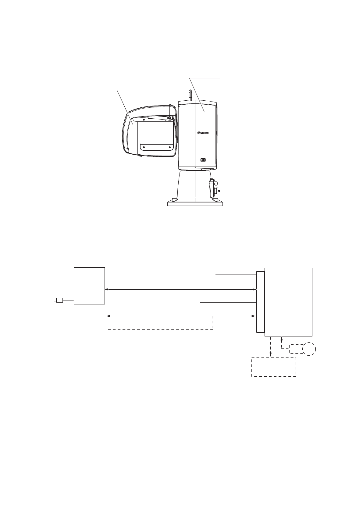
Overview
Camera housing unit
pan-tilt head
Remote camera
* Use the supplied control connector (for RS-422).
Operation unit
RS-422 *
Cable
(Provided by
the dealer)
DC Power supply
Receptacle
MIC
Washer
(Commercially
available)
GEN LOCK
12G-SDI
(MIC audio embedded)
Overview
System connections
Short distance transmission
For further information, please contact your Canon dealer or your Canon sales representative.
●
6
Page 7
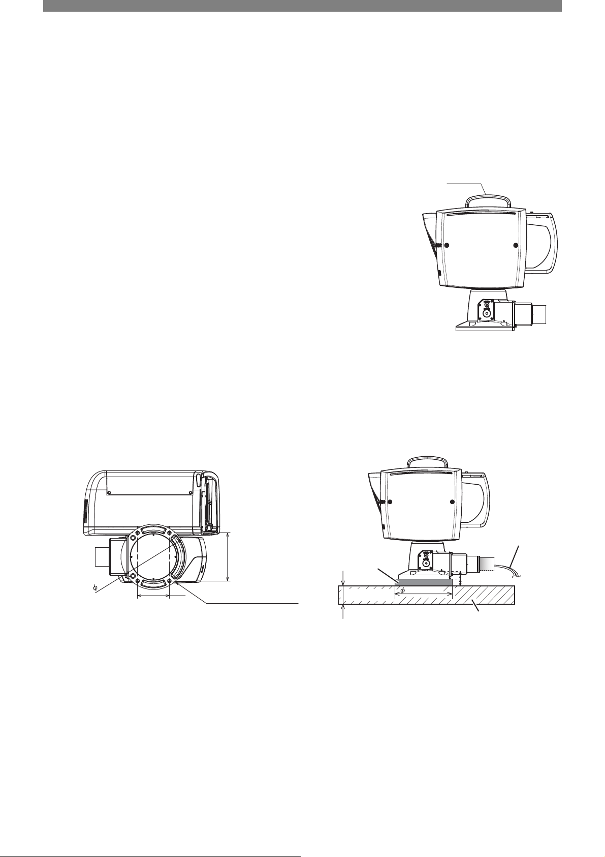
2
Handle
4xφ8.6
mounting bolts M8 x 1.25 L=35
Cable
Floor surface
Spacer (steel)
(If necessary)
t1=12mm or more
Handling of the unit
When carrying the unit, hold the unit by its handle. Be careful not to rotate the housing and
head forcibly.
Installation
Fixing of the unit
The dimensions for drilling the holes in the floor are shown below.
If necessary, prepare φ185 to 200 steel spacers to prevent interference between the floor and the cables. Use steel bolts with a
length that enables a screw-in depth of 12 mm or more into the floor, and fix the unit securely to a strong floor surface. Use a level to
check that the floor and the head unit are horizontal.
136
25
185
90
185 ~ 200
t2
Attaching the washer and microphone (optional)
To also install a washer or microphone, please obtain the mounting jigs (not included).
For more information about optional products, please contact your Canon dealer or your Canon sales representative.
7
Page 8
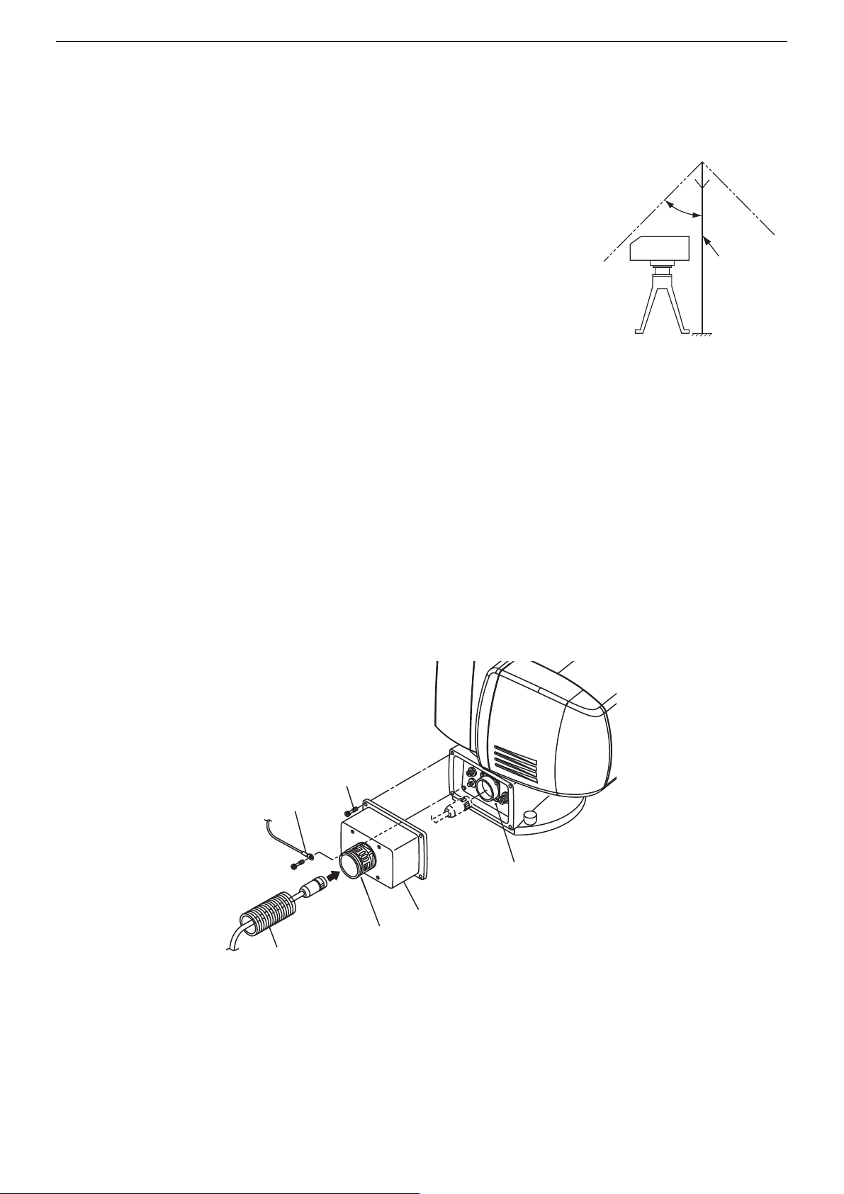
Installing a lightning rod
Lightning rod
Receptacle unit
Waterproof unit
Wate rproof conne cto r
Waterproof tube (L = 500 mm)
RohrFlex: RF-36 FLEXA
Wate rproof unit
mounting bolts (x4)
Fall prevention wire
(for waterproof unit)
Installing a lightning rod
If precautions need to be taken against lightning in case the system is to be installed on a hill-top
or other such location, provide a lightning rod as shown in the figure.
Make sure that the system will not touch the lightning rod when the camera is panned.
In the case of a permanent installation, safety is further enhanced by providing a lightning-proof
transformer for the system's power supply.
45°
Attaching a safety wire
In case a safety wire is necessary for the pan-tilt head, make sure to attach the wire to the handle section. When attaching the wires,
be careful that nothing blocks operation of the pan-tilt head.
Waterproofing the receptacle unit
Inspect the waterproof connector for looseness. After passing each cable through the waterproof tube and the waterproof unit, insert
the waterproof tube all the way into the waterproof connector until its tip touches the end and secure it in place. Put the end of the
waterproof tube in a safe place so that water, dust and moisture do not enter. Also, do not seal the end of the waterproof tube so as
to mitigate a pressure rise inside of the product caused by the temperature change. Connect each cable to the receptacle unit of the
main unit, and then secure the waterproof unit to the pan-tilt head using the supplied mounting bolts (x4).
Clamp the cables at appropriate intervals.
8
Page 9
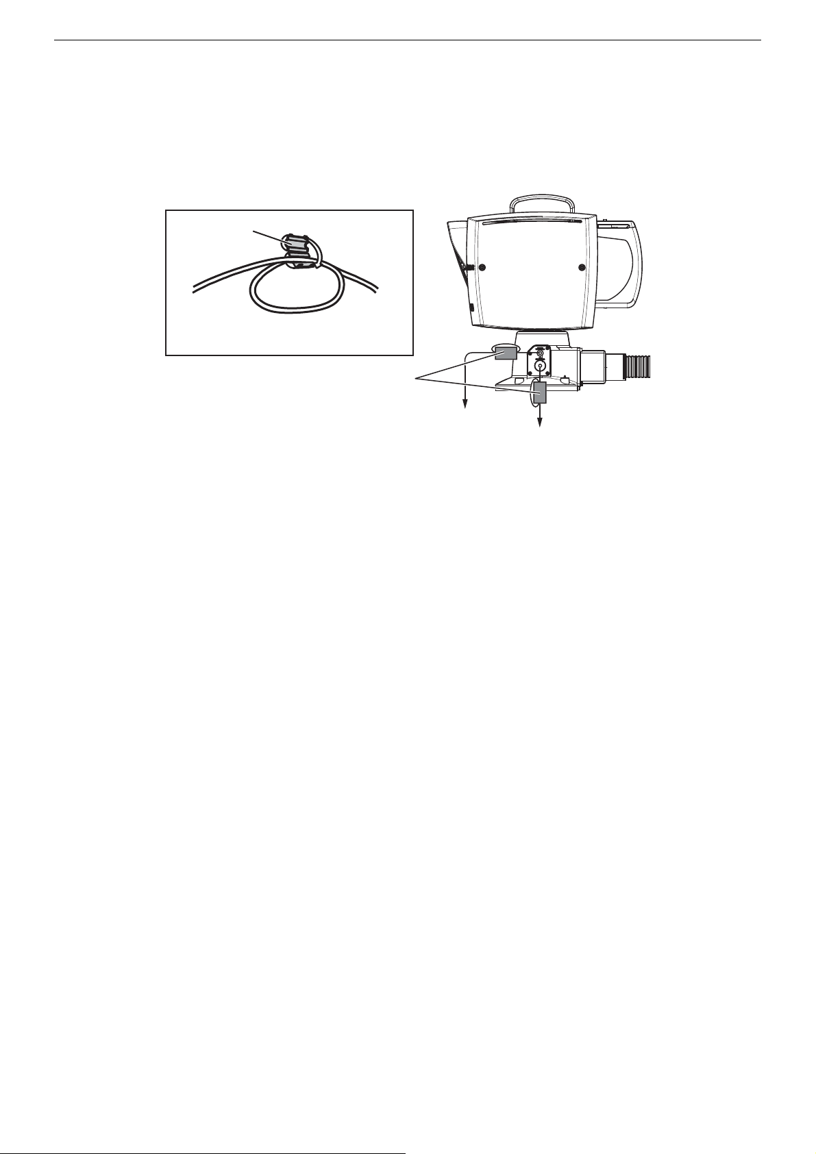
Connections
To t h e M I C u ni t
To th e w a s h e r
Ferrite core (supplied)
Make one loop
and then attach.
Ferrite core
Make one loop and attach the ferrite core to the cable
within 10 cm from the pan-tilt head connector.
Connections
When connecting each cable to the MIC terminal, the WASHER terminal, and AUX terminal, be sure to always use the ferrite core
supplied with this product.
9
Page 10
Details of operation and functions
IMPORTANT
IMPORTANT
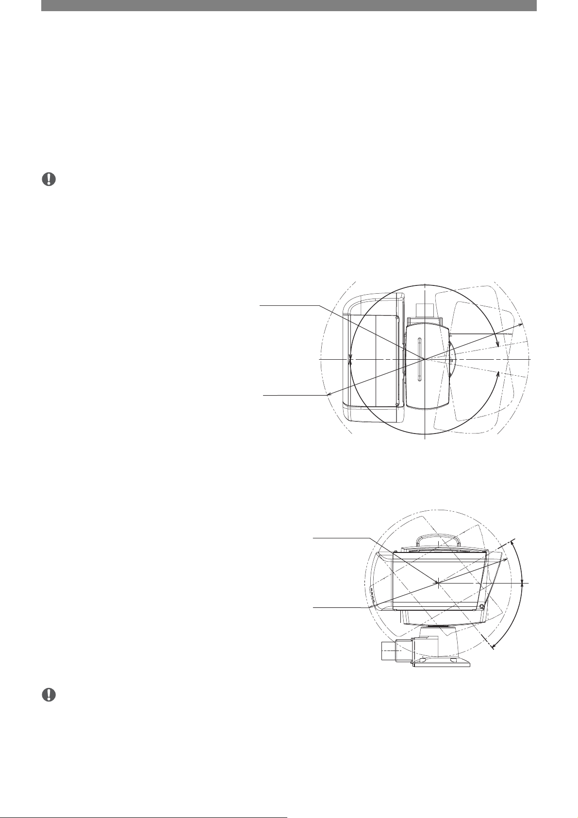
Center of PAN rotation
φ620
PAN s wi n g ra n ge
φ430
TILT swing range
Center of TILT rotation
3
Operation precautions
• The panning and tilting ranges may be off by about 5% due to zoom fluctuations caused by focusing, mounting errors of the pantilt head, etc. Check the actual panning and tilting ranges before proceeding to set to the subject.
Panning range
The panning range extends 170 degrees to the left and
right. This yields a turning range with a 620 mm
diameter which should be taken into account when
selecting the installation location.
Tilting range
The tilting range is approximately 430 mm when the pan-tilt head is
inclined upward at an angle of 30 degrees and downward at an angle
of 50 degrees: this should be taken into account when selecting the
installation location.
170°
170°
30°
• Do not turn the lens toward the sun. Strong light entering the lens when it is close to the Telephoto end may cause damage to the
lens and the camera.
10
50°
Page 11
Control connectors
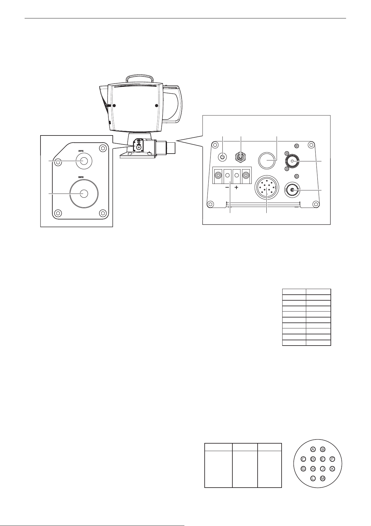
receptacle unit
AUX terminal's pin assignment
CONT. terminal's pin assignment
Pin No.
Input/output Signal name
Input
Output
Input
Output
Control connectors
②
①
WASHER
⑧
12V 500mA
MIC
12V 200mA
START
STOP
⑨
⑥⑦
① LED power indicator
This indicator illuminates when the power is on, and goes out when the power is turned off.
② Power switch
This is the switch for turning on/off the power.
③ AUX terminal
This terminal (HR10A-10R-10S (71) / HIROSE connector) is used to control optional functions. This
can be used as a universal contact circuit.
AUX
CONT.
③
SYNC
SDI
④
⑤
1
FPU
2
3
4
5
6
7
8
9
10
AUX1
AUX2
AUX3
AUX4
COM
④ SDI terminal
This is an output terminal (BNC connector) for uncompressed digital video and digital audio signals.
⑤ SYNC terminal
This is an input terminal (BNC connector) for external sync signals.
⑥ DC-IN terminal
This is an input terminal for DC power supply. Make sure to use a power cable that is suitable for the installation conditions
(authorized products, environmental regulations) and conforms to the product's power specifications. Power of two or three times
the rating 90 W may be consumed during power-on, so select a power supply with specifications that prevent a power failure.
⑦ CONT. terminal
This is an input terminal (EPRC05-R12M / TAJIMI connector) for the
pan-tilt head, lens and camera control signals.
A
B
D
E
J
RX+
TX+
RX-
TX-
GND
11
Page 12

Pan-tilt head, housing, lens, and camera operation
IMPORTANT
NOTES
⑧ Waterproof terminal for WASHER
This is the control terminal for the washer (optional).
⑨ Waterproof terminal for MIC
This is the control terminal for the microphone (optional).
Pan-tilt head, housing, lens, and camera operation
Pan-tilt head and built-in lenses and camera are controlled from the operation unit.
The functions and operating procedures vary depending on the operation unit that is used. For further information, please refer to the
instruction manual of your operation unit.
• It may take about 20 seconds to output steady video signals after the camera is turned on.
Genlock Synchronization
- When a suitable Genlock signal is input, the Genlock synchronization stabilizes after approximately 10 seconds.
- After the Genlock signal is input, do not perform other operations until the video output signal stabilizes or during the adjustment
of the phases.
• If you operate the zoom after focusing, the focus on the subject may be lost.
• If you focus manually and then leave the camcorder with the power turned on, the focus on the subject may be lost after a while.
This possible slight shift in focus is a result of the internal temperature rising in the camcorder and lens. Check the focus before
resuming shooting.
• In case abnormal focus performance is detected, turn the camera off and then on again.
12
Page 13
Custom picture settings
IMPORTANT
Custom picture settings
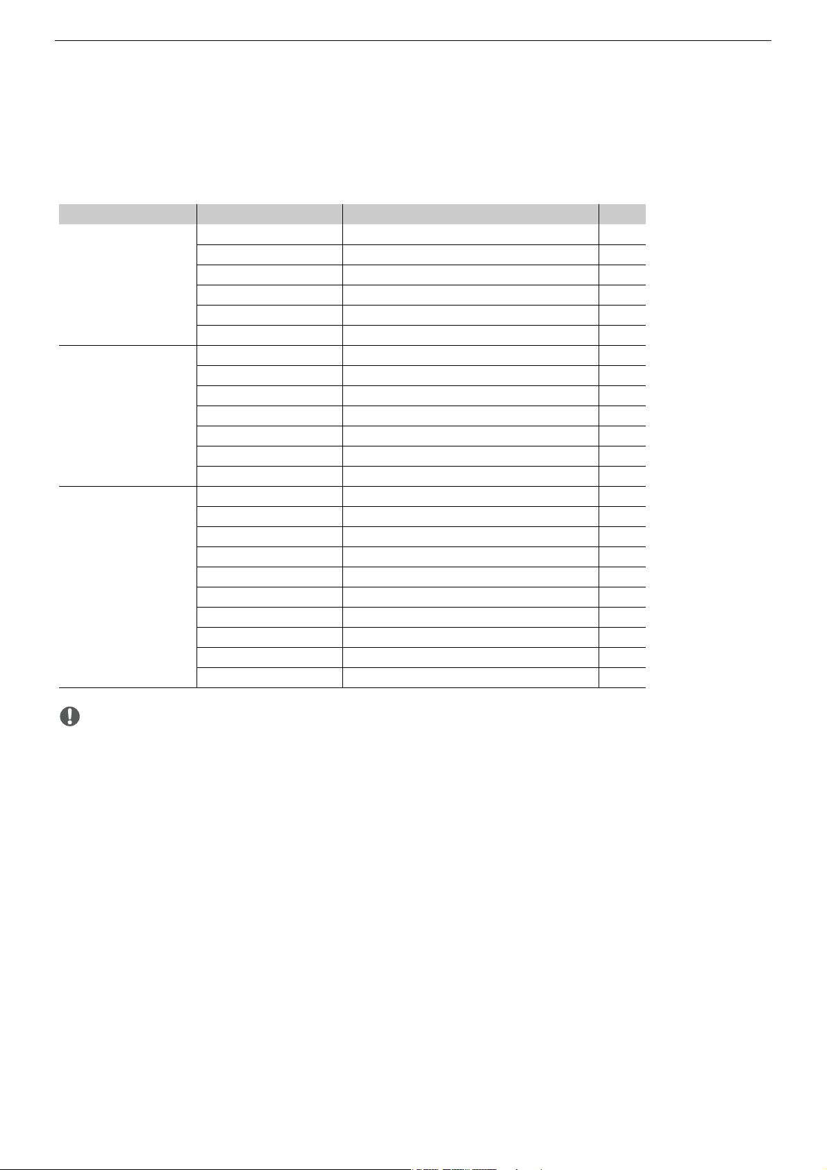
Using custom picture settings, you can change many settings that control various aspects of the image produced.
Available settings in Custom picture settings
Classification by settings Function Menu settings A
Gamma [Gamma] 15
Black gamma [Black Gamma] 16
Settings related to gradation
Settings related to peak and
noise
Settings related to color
directivity, intense and
conversion
Master pedestal [Black] - [Master Pedestal] 16
Master black [Black] - [Master Black] 16
Knee [Knee] 16
Over 100% [Other Functions] - [Over 100%] 18
Sharpness level [Sharpness] - [Level] 17
Sharpness frequency [Sharpness] - [Detail Frequency] 17
Sharpness HV balance [Sharpness] - [HV Detail Bal.] 17
Sharpness limit [Sharpness] - [Limit] 17
Coring level [Sharpness] - [Coring Level] 17
Noise reduction [Noise Reduction] 17
Skin detail [Skin Detail] 17
Color space [Color Space] 15
Color matrix [Color Matrix] 15
HLG Color [HLG Color] 15
Low key saturation [Low Key Satur.] 16
Knee saturation [Knee] - [Saturation] 16
Color gain [Color Matrix Tuning] - [Gain] 17
Color phase [Color Matrix Tuning] - [Phase] 17
Color tuning [Color Matrix Tuning] - [R-G], [R-B], [G-R], [G-B], [B-R], [B-G] 17
White balance [White Balance] 17
Color correction [Color Correction] 17
• If this product or the camera is turned off, adjusted values will be reset to default values.
13
Page 14
Custom picture settings
IMPORTANT
To change the setting of [Master Pedestal]:
Selecting custom picture settings
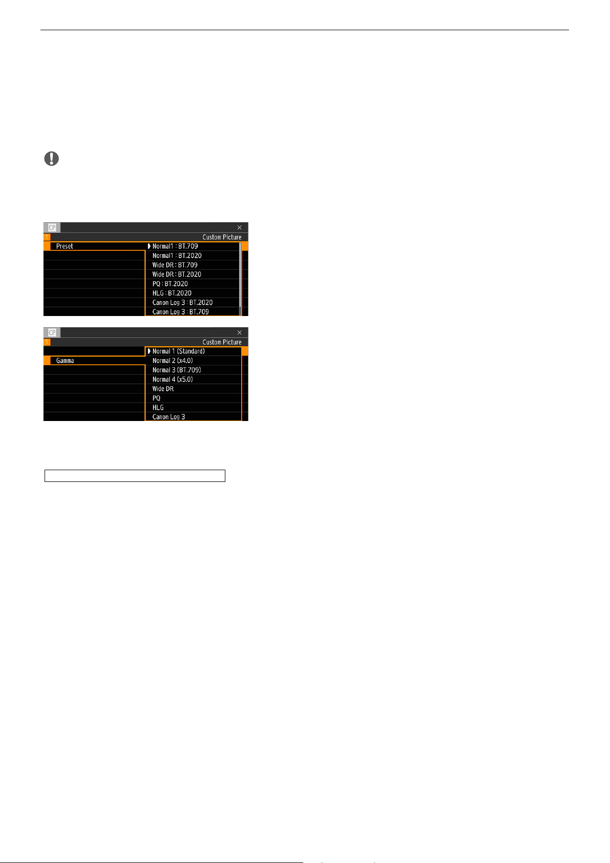
You can select custom picture settings while checking the [Custom Picture] menu displayed on external monitors using operation
unit.
• While the CP menu is displayed, do not perform other operations except adjusting custom picture settings.
Selecting the gamma curve, color space and color matrix
1 Select [/ Custom Picture]
2 Select the desired setting
• When not using the preset settings, select [Off] and continue the
procedure with step 3.
• To use one of the preset settings as is, the rest of the procedure is not
necessary.
3 Select [/ Custom Picture] [Gamma].
4 Select the desired setting
5 Select [/ Custom Picture]
Repeat step 5, selecting [Color Space] to select the color space, and/or
[Color Matrix] to select the color matrix in the same way.
Adjusting the image quality
1Select [/ Custom Picture] [Other Settings] [Black] [Master Pedestal].
2 Change the setting to the desired level
press .
[Preset].
press .
press .
[Color Space], [ColorMatrix].
14
Page 15
Custom picture settings
Input
Output
Input
Output
Input
Output
Available Custom Picture Settings
[/ ! Custom Picture] Menu
Menu items Setting options and additional information
[Preset] [Normal1 : BT.709], [Normal1 : BT.2020], [Wide DR : BT.709], [Wide DR : BT.2020], [PQ : BT.2020], [HLG : BT.2020], [Canon Log
3 : BT.2020], [Canon Log 3 : BT.709], [Off]
The camera offers a number of preset color settings (combinations of color space, gamma curve and color matrix).
[Off]: Select this setting when you want to set a different combination of custom picture settings with the individual custom
picture settings described below.
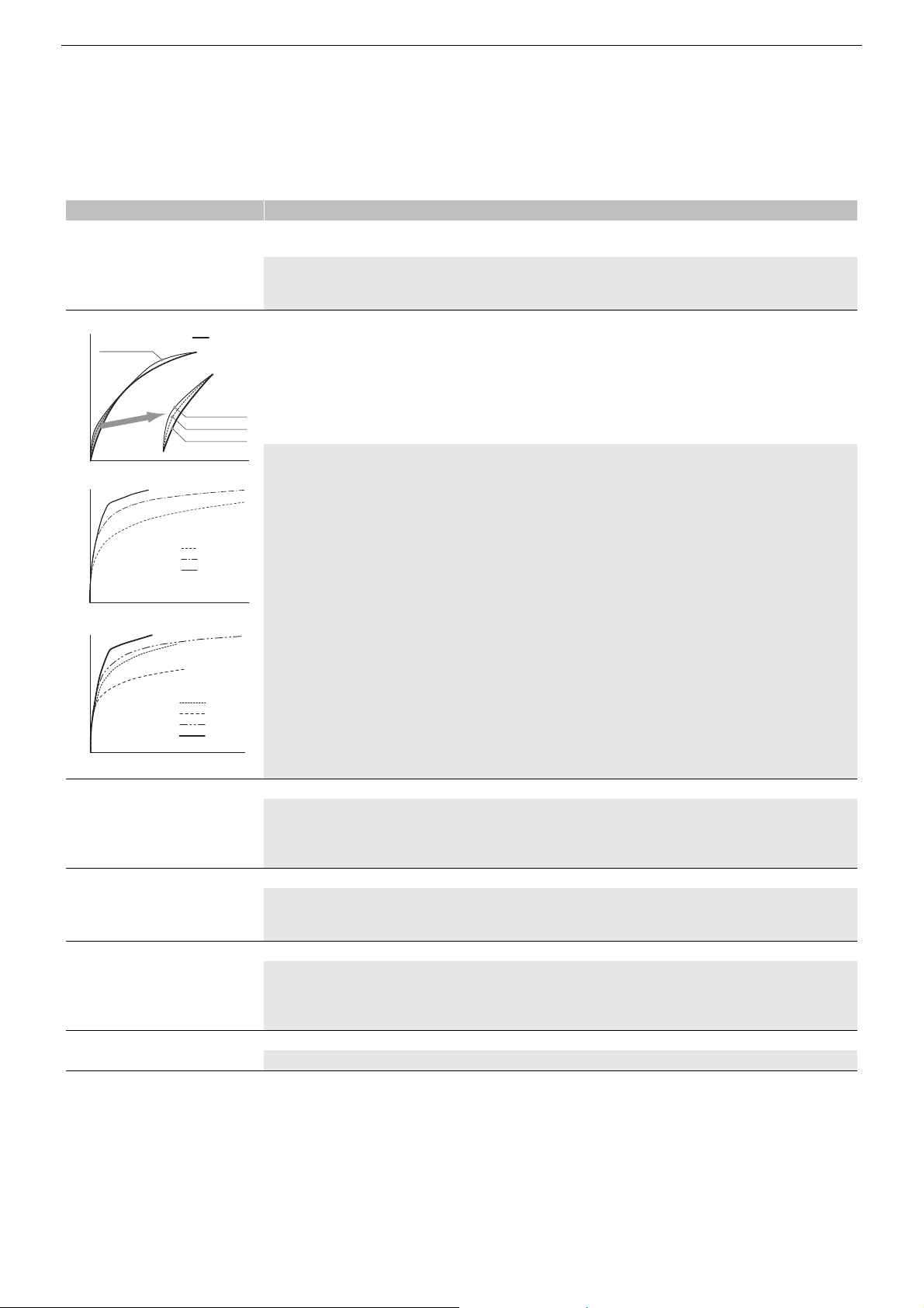
[Gamma] [Normal 1 (Standard)], [Normal 2 (x4.0)], [Normal 3 (BT.709)], [Normal 4 (x5.0)], [Wide DR], [PQ], [HLG], [Canon Log 3]
Normal 2/3/4
Normal 1
Normal 4
Normal 3
Normal 1/2
Canon Log 3
Wide DR
Normal1
Changes the overall look of the image.
[Normal 1 (Standard)]: Standard picture for playback on TV monitors.
[Normal 2 (x4.0)]: Setting suitable for playback on TV monitors. Produces brighter highlights (bright areas of the image) than
with the [Normal 1 (Standard)] setting.
[Normal 3 (BT.709)]: Setting suitable for playback on TV monitors. Produces a more faithful black gradation in the shadows (dark
areas of the image) than with the [Normal 2 (x4.0)] setting.
[Normal 4 (x5.0)]: Setting suitable for playback on TV monitors. Produces even better black gradation in the shadows (dark areas
of the image) than with the [Normal 3 (BT.709)] setting.
[Wide DR]: Gamma curve with a very wide dynamic range. Optimized for playback on TV monitors.
[PQ]: HDR (high dynamic range) gamma curve compliant with the PQ standard defined by ITU-R BT.2100.
[HLG]: HDR (high dynamic range) gamma curve compliant with the HLG standard defined by ITU-R BT.2100.
[Canon Log 3]: Logarithmic gamma curve that requires image processing in post-production.
HLG
PQ
WideDR
Normal1
[Color Space] [BT.2020 Gamut], [BT.709 Gamut]
Determines the color space of the image.
[BT.2020 Gamut]: Color space that meets ITU-R BT.2020 standards, which defines parameters for ultra-high-definition television
(4K/8K).
[BT.709 Gamut]: Standard color space that is compatible with sRGB specifications.
[Color Matrix] [Video], [Neutral]
The color matrix affects the overall color tonality of the image.
[Video]: Reproduces the colors of an EOS C300/EOS C500 camera with no custom picture settings applied.
[HLG Color] [BT.2100], [Vivid]
[Neutral]: Reproduces neutral colors.
Changes the quality of color reproduction when using the hybrid log gamma (HLG). This setting is only available when [Gamma]
is set to [HLG].
[BT.2100]: Color reproduction according to ITU-R BT.2100 specifications.
[Vivid]: More saturated color reproduction according to the 'Traditional Colour' approach in ITU-R BT.2390.
[Activate Other Settings] [On], [Off]
Use the default setting as is, and leave it unchanged.
15
Page 16
Custom picture settings
Input
Output
[Point]
[Range]
[Level]
Input
OutputOutput
Input
[Slope]
[Point]
[/ ! Custom Picture] > [Other Settings] Submenu (Detailed Settings)
Menu items Setting options and additional information
[Black]
[Master Pedestal] –50 to 50 (±0)
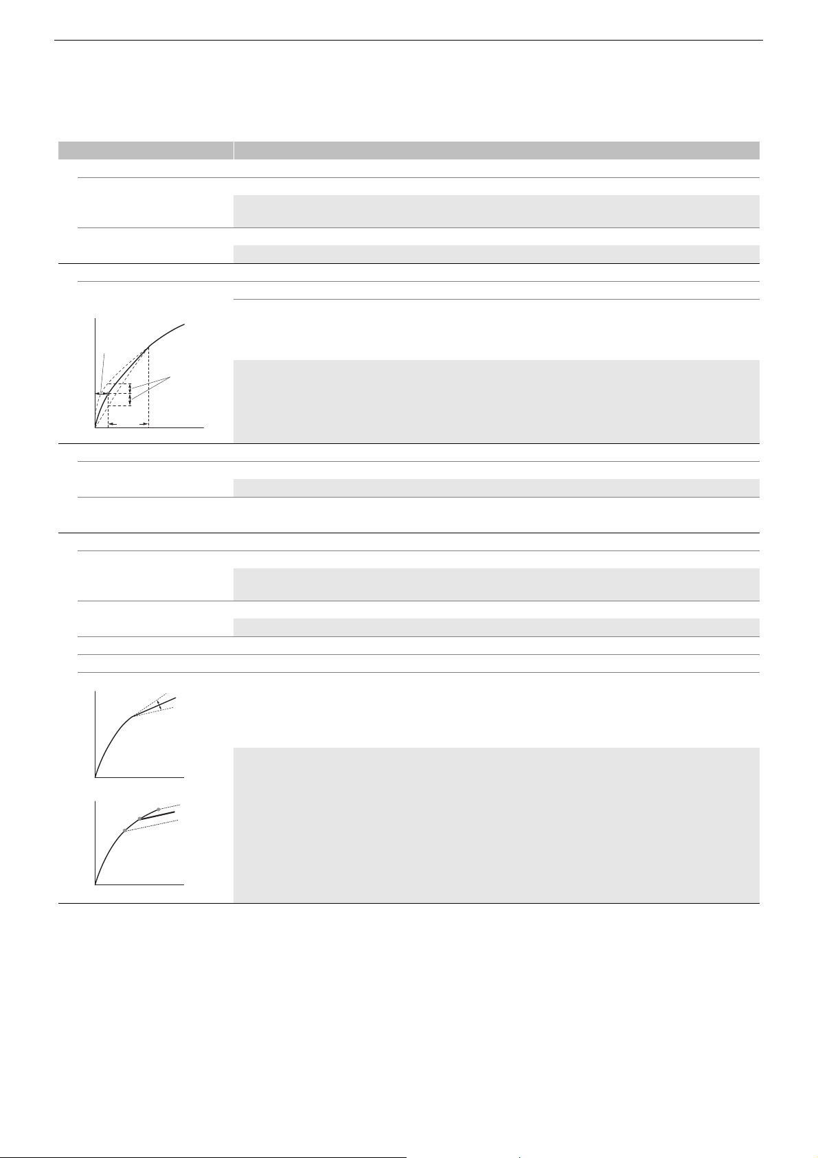
Increases or decreases the black level. Higher settings will make dark areas brighter but decrease contrast. When [Gamma] is
set to [Canon Log 3], this setting is not available.
[Master Black Red],
[Master Black Blue]
[Black Gamma]
[Level] –50 to 50 (±0)
[Range], [Point] –20 to 50 (±0)
[Low Key Satur.]
[Activate] [On], [Off]
[Level] –50 to 50 (±0)
[Knee]
[Activate] [On], [Off]
[Automatic] [On], [Off]
[Slope] –35 to 50 (±0)
[Point] 50 to 109 (95)
[Saturation] –10 to 10 (±0)
–50 to 50 (±0)
These settings correct the color cast in blacks. When [Gamma] is set to [Canon Log 3], these settings are not available.
These settings control the lower part of the gamma curve (dark areas of the image). When [Gamma] is set to [Wide DR], [PQ],
[HLG] or [Canon Log 3], these settings are not available.
[Level]: Raises or lowers the lower part of the gamma curve.
[Range]: Selects the adjustment range from the selected [Point].
[Point]: Determines the shape of the lower part of the gamma curve.
Set this setting to [On] to enable the adjustment of color saturation in dark areas with the [Level] setting.
Specifies how saturated colors are in dark areas.
Set this setting to [On] to enable the adjustment of the knee point with the following settings. When [Gamma] is set to [Wide DR],
[PQ], [HLG] or [Canon Log 3], the [Knee] settings are not available.
Set this setting to [On] to enable the automatic adjustment of the [Knee] settings.
16
These settings control the upper part of the gamma curve (highlights of the image). By compressing the highlights, you can
prevent parts of the image from being overexposed.
[Slope]: Determines the slope of the gamma curve above the knee point.
[Point]: Sets the knee point of the gamma curve.
[Saturation]: Adjusts the color saturation in the highlights.
Page 17

Menu items Setting options and additional information
[Sharpness]
[Level] –10 to 50 (±0)
Sets the sharpness level of the video output signal and the recorded signal.
[Detail Frequency] –8 to 8 (±0)
Sets the center frequency of horizontal sharpness. Setting higher values increases the frequency, which, in turn, increases the
sharpness.
[Coring Level] –30 to 50 (±0)
Sets the level of correction of artifacts caused by high sharpness levels (coring). Higher values prevent sharpness from being
applied to minute details, resulting in less noise.
[HV Detail Bal.] –8 to 8 (±0)
Adjusts the ratio between horizontal and vertical detail. Higher values emphasize vertical detail while lower values emphasize
horizontal detail.
[Limit] –50 to 50 (±0)
Restricts how much sharpness is applied.
[Noise Reduction]
[Level] [Automatic],1 (lowest level) to 12 (highest level), [Off]
Reduces the amount of noise that appears in the image.
[Skin Detail]
[Effect Level] [High], [Middle], [Low], [Off]
[Hue] –16 to 16 (±0)
[Chroma], [Area], [Y Level] 0 to 31 (16)
The camera applies a softening filter to areas in the picture with skin tones to give a more pleasant appearance. By changing
these settings, you can determine what areas will be detected as skin tones. A zebra pattern will appear on the screen over
areas of the image that are detected as having skin tones.
[Effect Level]: Adjusts the level of the filter.
[Hue]: Adjusts the hue for detection of skin tones.
[Chroma]: Adjusts the color saturation for detection of skin tones.
[Area]: Adjusts the color range for detection of skin tones.
[Y Level]: Adjusts the brightness for detection of skin tones.
[White Balance]
[R Gain], [B Gain] –50 to 50 (±0)
These settings adjust the amount of white balance throughout the whole image by changing the intensity of red tones ([R gain])
and blue tones ([B Gain]).
[Color Matrix Tuning]
[Gain] –50 to 50 (±0)
[Phase] –18 to 18 (±0)
These settings adjust the color intensity ([Gain]) and color phase ([Phase]) of the color matrix, affecting the color tones of the
whole image.
[R-G], [R-B], [G-R], [G-B],
[B-R], [B-G]
[Color Correction]
[Select Area] [Area A&B], [Area B], [Area A], [Off]
[Area A Setting Phase],
[Area B Setting Phase]
[Area A Setting Chroma],
[Area A Setting Area],
[Area A Setting Y Level],
[Area B Setting Chroma],
[Area B Setting Area],
[Area B Setting Y Level]
–50 to 50 (±0)
Each matrix changes the tint of the picture along the color gradations detailed below, affecting the color tones of the whole
image.
[R-G]: cyan/green and red/magenta; [R-B]: cyan/blue and red/yellow;
[G-R]: magenta/red and green/cyan; [G-B]: magenta/blue and green/yellow;
[B-R]: yellow/red and blue/cyan; [B-G]: yellow/green and blue/magenta.
The camera detects areas with certain color characteristics (color phase, chroma, area and Y level) and corrects them when
recording. You can set the color correction for up to two different areas
(A and B) and apply the color correction to either one ([Area A] or [Area B]) or both of them ([Area A&B]). While color correction is
activated, a zebra pattern will appear on the screen over areas of the image detected as having the characteristics specified for
area A or area B.
0 to 31 (0)
These settings determine the color phase of the area to be corrected (A or B, respectively).
0 to 31 (16)
These settings determine the following color characteristics of the area to be corrected (A or B, respectively).
[Area A Setting Chroma], [Area B Setting Chroma]: Color saturation.
[Area A Setting Area], [Area B Setting Area]: Color range.
[Area A Setting Y Level], [Area B Setting Y Level]: Brightness.
Custom picture settings
17
Page 18

Custom picture settings
Menu items Setting options and additional information
[Area A Revision Level],
[Area B Revision Level]
[Area A Revision Phase],
[Area B Revision Phase]
[Other Functions]
[Over 100%] [Through], [Press], [Clip]
[File] This function is not available for this product. Do not operate it.
–50 to 50 (±0)
These settings adjust the amount of correction applied to the color saturation in the corrected area
(A or B, respectively).
–18 to 18 (±0)
These settings adjust the amount of correction applied to the color phase in the corrected area
(A or B, respectively).
Determines how the camera handles video signals exceeding 100%. When [Gamma] is set to [PQ], [HLG] or [Canon Log 3], this
setting is not available.
[Through]: Leave the signal unchanged.
[Clip]: Clip the signal at 100%.
[Press]: Compress a signal of up to 108% down to 100% levels.
18
Page 19

4
Troubleshooting
Additional information
Symptom
Communication is not possible with the
operation unit.
Camera control does not work. Installation site • Check the power to the pan-tilt head.
No video is displayed although the pantilt head can be operated.
The pan-tilt head does not move. Installation site • This may be due to an outside factor such as strong wind or some obstacle.
The custom picture settings cannot be
selected using the operation unit.
Site where check is
required
Installation site • Check that each cable is connected correctly.
• Check that the control cable for pan-tilt head and the cable for camera are connected correctly.
• Conduct a continuity check for broken cable wires, etc.
Installation site • Conduct a continuity check for broken cable wires, etc. (Disconnect the BNC and check the video
from the pan-tilt head.)
Check and remove any obstructing factors, and perform the operation again.
Installation site • [Activate Other Settings] in the custom picture settings was set to [Off]. Turn the camera off and
then on again.
Check and confirm
19
Page 20
Specifications
Specifications
Camera unit
Available menu items may vary depending on the operation unit used.
Imaging sensor Type 1.0 (1.0 in.) single-plate CMOS sensor, effective pixels: approximate 8,290,000 pixels
Mounted camera 8.3 to 124.5 mm F2.8 to 4.5, approximate 6.4 to 96 mm (Type 2/3 equivalent)
15x optical zoom, 30x advanced zoom (only when the resolution is 1920x1080)
Video Output
Configuration
Default Video
Output
Configuration
Focusing system AUTO, MANUAL
IRIS AUTO, MANUAL
Image stabilizer Optical shift type
Shutter speed AUTO
Gain AUTO
ND filter OFF, 1/4, 1/16, 1/64
White balance AUTO, Set A, Set B, Daylight, Tungsten, Kelvin
Available Custom
Picture Settings
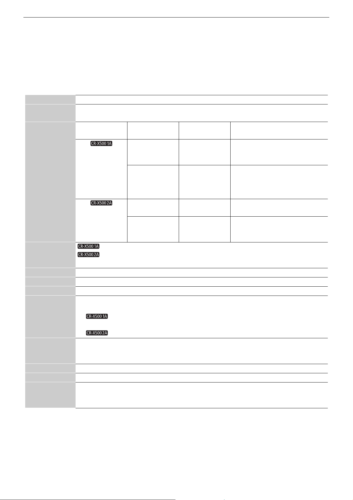
Model Resolution* Frame rate* Video Output Configuration
3840x2160 59.94P
29.97P
23.98P
1920x1080 59.94P
59.94i
29.97P
23.98P
3840x2160 50.00P
25.00P
1920x1080 50.00P
50.00i
25.00P
1920x1080 59.94P
1920x1080 50.00P
MANUAL
59.94P / 59.94i / 29.97P: 1/4 to 1/2000
23.98P: 1/3 to 1/2000
1/3 to 1/2000
MANUAL
-6, -3, 0, 3, 6, 9, 12, 15, 18, 21, 24, 27, 30, 33 dB
White balance (R /B gain), Master pedestal, Master black (R / B),
Preset custom picture settings (Gamma, Color Space, Color Matrix), Black Gamma, Knee,
Sharpness, Noise Reduction, Skin Detail, Color Matrix
3840x2160 59.94P
3840x2160 29.97P
3840x2160 23.98P
1920x1080 59.94P
1920x1080 59.94i
1920x1080 29.97P
1920x1080 23.98P
3840x2160 50.00P
3840x2160 25.00P
1920x1080 50.00P
1920x1080 50.00i
1920x1080 25.00P
* For more information about video output configuration, please contact your Canon dealer or your Canon sales representative.
20
Page 21

Head unit (Pan-tilt section)
Specifications
Ambient operating
conditions
Wind speed
resistance
Power supply 10.5 to 15 V DC, 90 W
Wiper Provided
MIC input Provided (Pedestal section)
Washer Control terminal provided (Pedestal section)
Pan-tilt head
operations
Shot operations Pan/tilt/zoom/focus
Stopping accuracy For both pan and tilt operations less than 7' when no external forces are applied, less than 6' when external
Dustproof and
waterproof
performance
Acoustic noise NC55 or less*
Control cable RS-422 cable
Receptacle DC, control (RS-422), SDI output, SYNC input, AUX
Video output BNC1 system, 12G-SDI, 6G-SDI, 3G-SDI, HD-SDI output, embedded audio
GENLOCK input BNC1 system (tri-value/BB)
Pan-tilt head
securing
Dimensions Refer to the external view (A 22).
Mass Approx. 17 kg (including the camera, excluding the optional units)
Temperature: -15 to +40°C, Humidity: 90%RH or less (non-condensing)
0 to 25 m/s: Operate normally, 25 to 35 m/s: Operable, 35 to 60 m/s: Not destroyed
Power of two or three times the rating 90 W may be consumed during power-on, so select a power supply
with specifications that prevent a power failure.
Operation angle Operation speed
Panning -170° to +170°±5° 0.5°/s to 25°/s
Tilting -50° to +30°±5° 0.3°/s to 20°/s
forces are applied
IP55
* NC55 or less when operating speed is 10°/s or less
Depending on the system configuration, other unit or cable may be required.
Mounted with four M8 bolts
21
Page 22
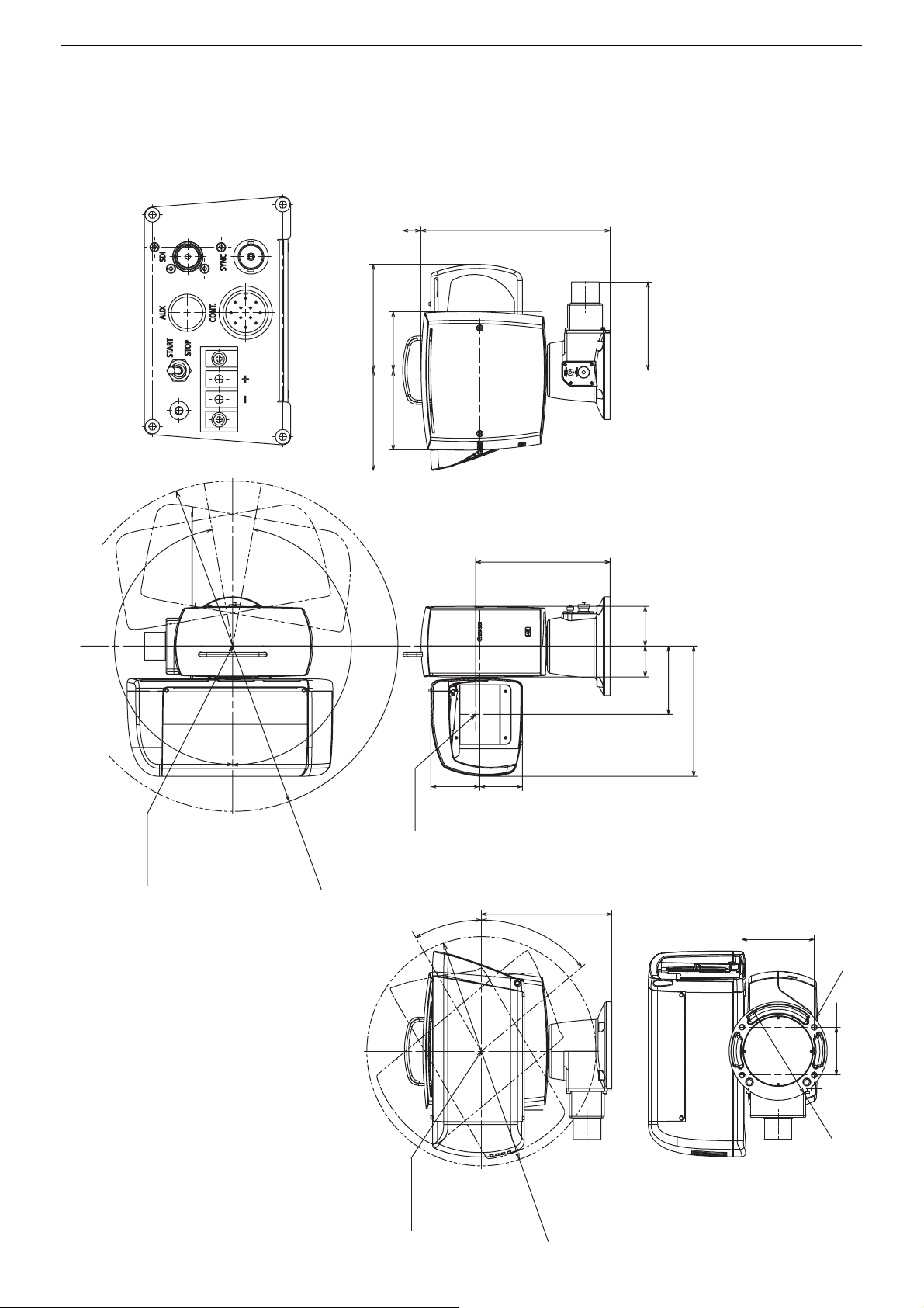
External View
30°
50°
φ185
φ430
4xφ8.6
Mounting bolts M8 x 1.25 L=35
TILT swing range
Center of
TILT rotation
245
136
90
External View
Receptacle unit (1:1)
150 110
188 198
356 34
(Unit : mm)
165.5
170°
Center of
PAN rotation
620
φ
PAN swing range
170°
Optical axis
252
74.558
128
244
80 92
22
Page 23

Index
A
AUX terminal . . . . . . . . . . . . . . . . . . . . . . . . . . . . . . . . 11
C
Camera housing . . . . . . . . . . . . . . . . . . . . . . . . . . . . . . . 6
Camera unit . . . . . . . . . . . . . . . . . . . . . . . . . . . . . . . . . 20
Components . . . . . . . . . . . . . . . . . . . . . . . . . . . . . . . . . 5
Connections . . . . . . . . . . . . . . . . . . . . . . . . . . . . . . . . . . 9
CONT. terminal . . . . . . . . . . . . . . . . . . . . . . . . . . . . . . . 11
Control connectors . . . . . . . . . . . . . . . . . . . . . . . . . . . . 11
Custom picture . . . . . . . . . . . . . . . . . . . . . . . . . . . . . . . 13
D
DC-IN terminal . . . . . . . . . . . . . . . . . . . . . . . . . . . . . . . 11
E
External View . . . . . . . . . . . . . . . . . . . . . . . . . . . . . . . . 22
F
Ferrite core . . . . . . . . . . . . . . . . . . . . . . . . . . . . . . . . . . . 9
H
Handling . . . . . . . . . . . . . . . . . . . . . . . . . . . . . . . . . . . . . 7
Head unit . . . . . . . . . . . . . . . . . . . . . . . . . . . . . . . . . . . 21
I
image settings . . . . . . . . . . . . . . . . . . . . . . . . . . . . . . . 13
Installation . . . . . . . . . . . . . . . . . . . . . . . . . . . . . . . . . . . 7
L
LED power indicator . . . . . . . . . . . . . . . . . . . . . . . . . . . 11
lightning rod . . . . . . . . . . . . . . . . . . . . . . . . . . . . . . . . . . 8
M
Microphone . . . . . . . . . . . . . . . . . . . . . . . . . . . . .7, 9, 12
O
Operation unit . . . . . . . . . . . . . . . . . . . . . . . . . . . . . . . . . 6
P
Panning . . . . . . . . . . . . . . . . . . . . . . . . . . . . . . . . . . . . 10
pan-tilt head . . . . . . . . . . . . . . . . . . . . . . . . . . . . . . . . . .6
Power switch . . . . . . . . . . . . . . . . . . . . . . . . . . . . . . . .11
R
Range . . . . . . . . . . . . . . . . . . . . . . . . . . . . . . . . . . . . . . 10
Receptacle . . . . . . . . . . . . . . . . . . . . . . . . . . . . . . . .6, 11
S
Safety wire . . . . . . . . . . . . . . . . . . . . . . . . . . . . . . . . . . .8
SDI terminal . . . . . . . . . . . . . . . . . . . . . . . . . . . . . . . . . 11
Specifications . . . . . . . . . . . . . . . . . . . . . . . . . . . . . . . .20
SYNC terminal . . . . . . . . . . . . . . . . . . . . . . . . . . . . . . .11
System connections . . . . . . . . . . . . . . . . . . . . . . . . . . . . 6
T
Tilt . . . . . . . . . . . . . . . . . . . . . . . . . . . . . . . . . . . . . . . . 10
Troubleshooting . . . . . . . . . . . . . . . . . . . . . . . . . . . . . . 19
W
Washer . . . . . . . . . . . . . . . . . . . . . . . . . . . . . . . . .7, 9, 12
Waterproof terminal for MIC . . . . . . . . . . . . . . . . . . . . . 12
Waterproof terminal for WASHER . . . . . . . . . . . . . . . . .12
Waterproof tube . . . . . . . . . . . . . . . . . . . . . . . . . . . . . . . 8
Waterproofing . . . . . . . . . . . . . . . . . . . . . . . . . . . . . . . . . 8
23
Page 24

各販売地域のお問い合わせ先 / Inquiries (by Sales Region) /
各销售地区的咨询方式
AMERICAS
Brazil _______________________________________________________ Canon do Brasil Industria e Comercio Ltda.
http://www.canon.com.br/suporte
Tel: +55 (11) 4950-5060 (Sao Paulo capital only),
+55 0800 20 22666 for others
Canada _____________________________________________________ Canon Canada, Inc.
http://canon.ca/en/Contact-Support/Pro-Photo-Video
Tel: +1-800-652-2666
Mexico ______________________________________________________ Canon Mexicana, S. de R.L. de C.V.
http://www.canon.com.mx/servicio/contactanos
Tel:+52 55 5249 4900
USA_________________________________________________________ Canon U.S.A., Inc.
https://www.usa.canon.com/internet/portal/us/home/support/
Tel(BCTV) : 800-423-5367(USA Only)
Tel(Cinema Lens) : 855-246-3367(USA Only)
ASIA
CHINA ______________________________________________________ 佳能 (中国)有限公司
http://www.canon.com.cn/supports/service.html
电话:+86(0)10-8513-9999
JAPAN ______________________________________________________
_________________________________________________캐논코리아(주)
Korea
http://www.canon-ci.co.kr
South & Southeast Asia ______________________________________ Canon Singapore Pte. Ltd.
TAIWAN _____________________________________________________ Canon Marketing (Taiwan) Co., Ltd.
キヤノンマーケティングジャパン株式会社
http://canon.jp
Tel: (03) 3740-3305
https://asia.canon/en/business
https://tw.canon/zh_TW/business
EUROPE, MIDDLE EAST, AFRICA
_____________________________________________________________ Canon Europe Ltd.
http://www.canon-europe.com
Tel:+44(0)20-8588-8000
OCEANIA
_____________________________________________________________ Canon Australia Pty. Ltd.
http://www.canon.com.au
24
Page 25

© CANON INC. 2022
The information in this document is verified as of June 2022. Subject to change without notice.
Visit your local Canon website to download the latest version.
Canon Inc.
30-2, Shimomaruko 3-chome, Ohta-ku, Tokyo 146-8501, Japan
Canon Europa N.V.
Bovenkerkerweg 59, 1185 XB Amstelveen, The Netherlands http://www.canon-europe.com
 Loading...