

Canon ColorPASS-GX400 Installation Procedure

ColorPASS-GX400 Installation Procedure
ColorPASS-GX400 設置手順書
This installation procedure is written in Japanese and English. The installation procedure for Japan model is described in Japanese and one for the other models is
described in English. These procedures are different from each other. Follow the procedure corresponding to the installed model.
- Japanese: The installation procedure for Japan model
- English: The installation procedure for the other models except for Japan model
この設置手順書には、和文と英文の設置手順が記載されている。和文では日本モデル用の設置手順が記載されており、英文では日本モデル以外のその他のモデル用の設
置手順が記載されている。それぞれの設置手順は異なっているので、モデルに応じた手順に従うこと。
・和文: 日本モデル用設置手順
・英文: 日本モデル以外のその他のモデル用設置手順
PRINTED IN USA 45110308 PUB No. FT1-0695-000
ENGLISH
日本語
Before Connection > Items to Prepare in Advance
2
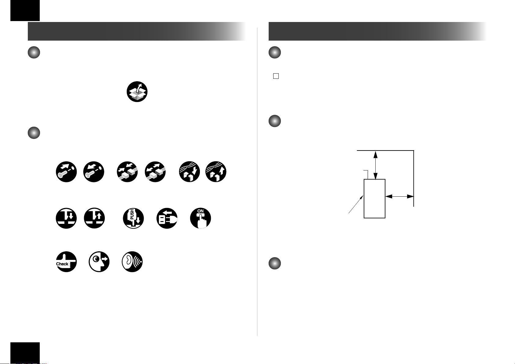
How to Check this Installation Procedure
When Using the Parts Included in the Package
A symbol is described on the illustration in the case of using the parts included in the package
of this product.
Packaged Item
F-1-1
Smbols in the Illustration
The frequently-performed operations are described with symbols in this procedure.
Plug in
Harness
Secure Free
Turn on
Screw
Tighten
Claw
Insert
Checking instruction
Remove Connect
Remove
Connector
Disconnect
Push
Before Connection
The IP addresses for communication between the host
machine and server are set automatically
1) Enter the Service Mode (level 1).
2) Select COPIER > OPTION > INT-FACE > IMG-CONT > "3".
3) Exit the Service Mode.
Securing space for installation
Secure a space to install this equipment as shown in the gure below. A space of 200 mm or
more is required from the back of this equipment.
200mm+ (8 in.)
Rear
200mm+
(8 in.)
PS Unit
Front
<Top view>
F-1-3
Sound CheckCheck Visual Check
Before Connection > Items to Prepare in Advance
F-1-2
Items to Prepare in Advance
• Mouse
• Monitor
• Keyboard
2
Installation Procedure > In the case iR-ADV C5255/C5250/C5240/C5235 Series > Installing the Open I/F PCB
3
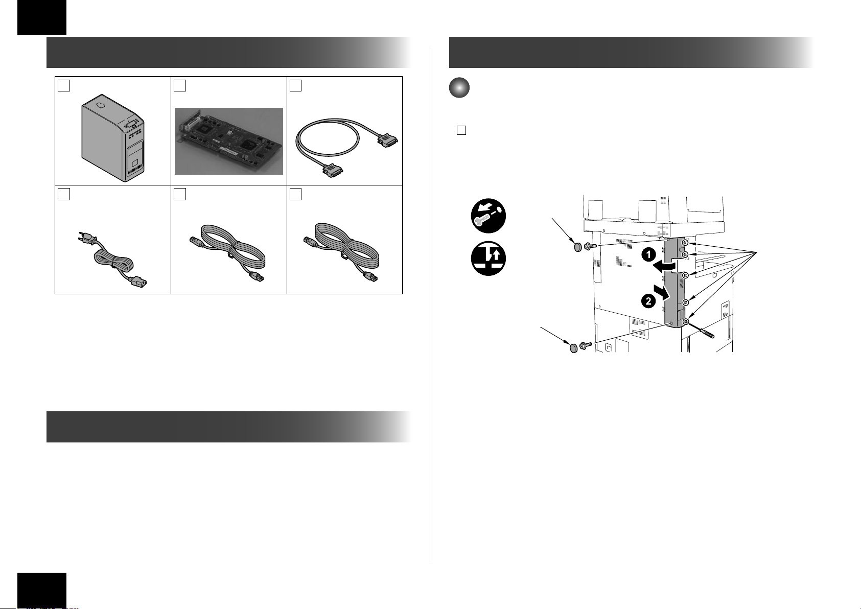
Checking the Contents
[1] PS Unit X 1 [2] Open I/F PCB X 1
[4] Power Cord [5] Cross Ethernet
Europe x 2
Cable 3.0m X1
USA x 1
[4] Power Cord: The connector has a different shape depending on locations.
Use the correct power code to mach the location/area of installation.
Make sure not to leave unused power code at the site.
[3] Interface Cable X 1
[6] Shield Ethernet
Cable 3.0m X1
Installation Procedure
In the case iR-ADV C5255/C5250/C5240/C5235 Series
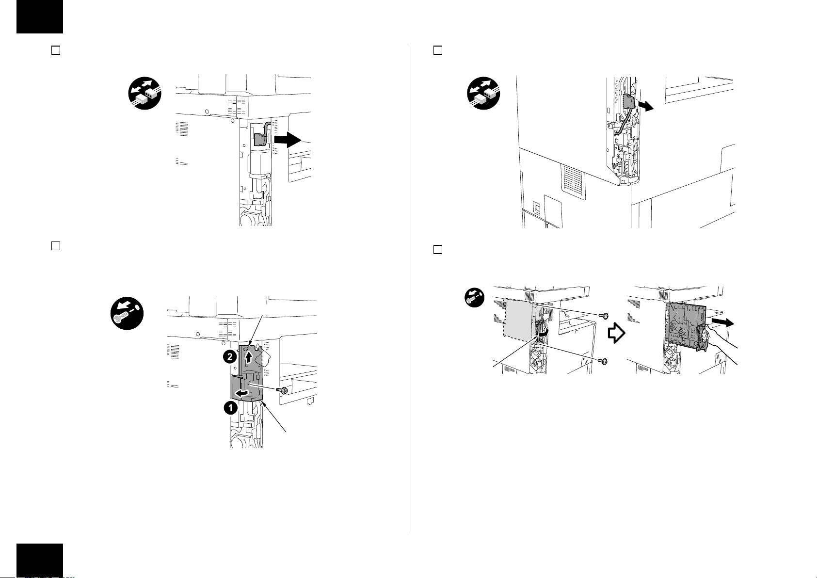
■Installing the Open I/F PCB
1) Remove the Left Rear Cover.
• 2 Rubber Caps
• 2 Screws
• 5 Claws
Rubber Caps
x2
Claws
x5
F-1-4
Rubber Caps
< CD/Guides >
• Media Pack
Check Items when Turning OFF the Main Power
Check that the main power switch is OFF.
1) Turn OFF the main power switch of the host machine.
2) Be sure that display in the Control Panel and the lamp of the main power supply are turned
off, then disconnect the power plug.
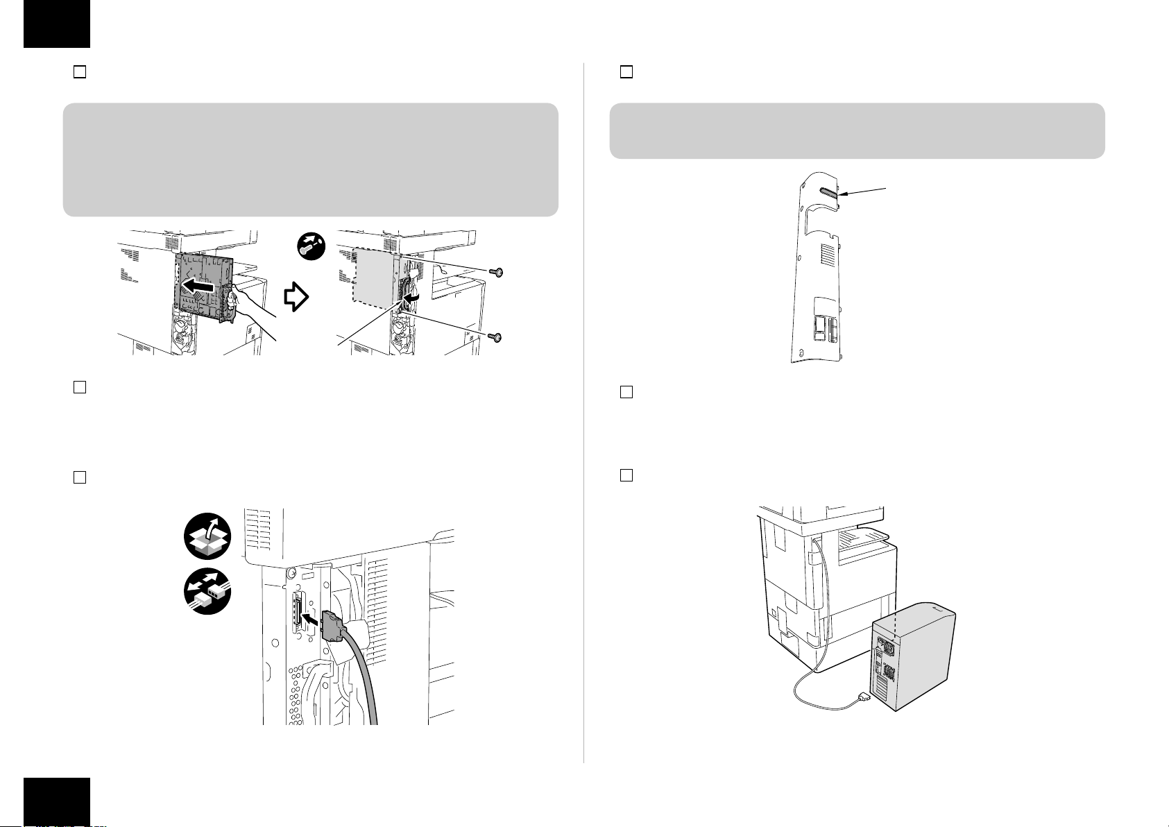
Installation Procedure > In the case iR-ADV C5255/C5250/C5240/C5235 Series > Installing the Open I/F PCB
F-1-5
3
Installation Procedure > In the case iR-ADV C5255/C5250/C5240/C5235 Series > Installing the Open I/F PCB
4
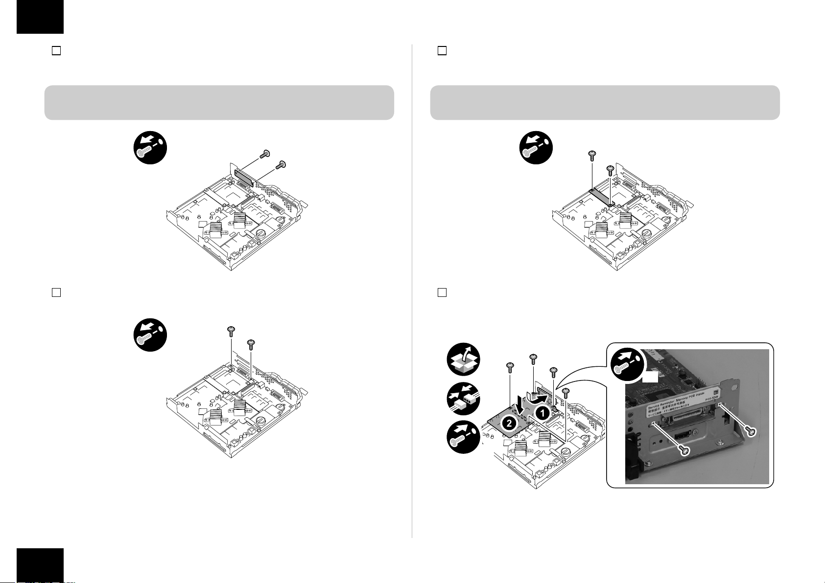
2) When the Reader is installed, remove the Reader Communication Cable.
F-1-6
3) Remove the Left Rear Sub Cover.
• 1 Screw
• 1 Hook
Hook
4) When the FAX is installed, remove the FAX cable.
F-1-8
5) Hold the handle to remove Main Controller PCB 2.
• 2 Screws
x2
Left Rear
Sub Cover
F-1-7
Installation Procedure > In the case iR-ADV C5255/C5250/C5240/C5235 Series > Installing the Open I/F PCB
Grip
F-1-9
4
Installation Procedure > In the case iR-ADV C5255/C5250/C5240/C5235 Series > Installing the Open I/F PCB
5
6) Remove the Face Cover. (Removed Face Cover is not used.)
• 2 Screws (the removed screws are used in step 9))
NOTE:
Ask the user to store the Face Cover, in case it is needed in the future.
x2
7) Remove the 2 screws. (the removed screws are used in step 9))
F-1-10
8) Remove the Bypass PCB (the removed Bypass PCB is not used).
• 2 Screws (the removed screws are used in step 9))
NOTE:
Ask the user to store the Bypass PCB, in case it is needed in the future.
x2
F-1-12
9) Install the Open I/F PCB.
• 1 Connector
• 6 Screws (the screws removed in step 6), 7) and 8))
x2
F-1-11
Installation Procedure > In the case iR-ADV C5255/C5250/C5240/C5235 Series > Installing the Open I/F PCB
x2
x4
F-1-13
5
Installation Procedure > In the case iR-ADV C5255/C5250/C5240/C5235 Series > Installing the PS Unit
6
10) Install Main Controller PCB 2.
CAUTION:
• Lift the grip and insert the Main Controller PCB 2. When it touches the end, tilt the
grip and install it with 2 screws.
• Make sure to tilt the grip slowly on both sides simultaneously.
• Check that the Main Controller PCB 2 is installed properly.
x2
Grip
F-1-14
11) Install the FAX Cable (if the FAX is installed).
12) Install the Left Rear Sub Cover. (1 Screw)
13) Install the Reader Communication Cable (if the Reader is installed).
15) Cut off [A] part of the Left Rear Cover with nippers.
CAUTION:
Be sure to remove adequately so that there is no burr.
[A]
F-1-16
16) Install the Left Reader Cover. (2 Screws, 2 Rubber Caps)
■Installing the PS Unit
14) Connect the Interface Cable to the installed Open I/F PCB.
F-1-15
Installation Procedure > In the case iR-ADV C5255/C5250/C5240/C5235 Series > Installing the PS Unit
1) Install the PS Unit to the left side of the host machine.
F-1-17
6
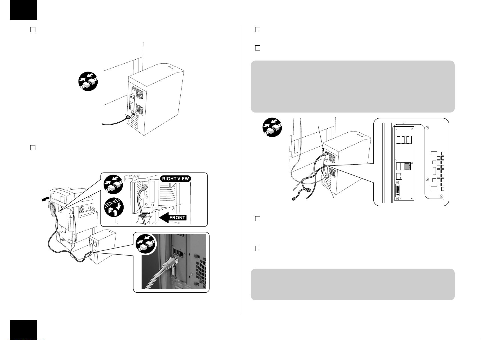
Installation Procedure > In the case iR-ADV C5255/C5250/C5240/C5235 Series > Installing the PS Unit
7
2) Connect the Interface Cable to the PS Unit.
3) Open the Right Rear Cover 1 to install the Cross Ethernet Cable.
• 1 Wire Saddle
F-1-18
Wire Saddle
4) Close the Right Rear Cover 1.
5) Connect the Power Cord and the Shield Ethernet Cable to the PS Unit.
CAUTION:
• Use the correct power code to mach the location/area of installation. Make sure not
to leave unused power code at the site.
• Be sure to use the network cable with Category 5e or higher. In addition, a sealed
type (STP cable) is recommended. When using the non-sealed type (UTP cable),
it may inuence the surrounding electronic equipments via network cable.
Power Cord
x2
Shield Ethernet Cable
F-1-20
F-1-19
Installation Procedure > In the case iR-ADV C5255/C5250/C5240/C5235 Series > Installing the PS Unit
6) Plug the power cord into an outlet.
7) Turn the PS Unit power on, then turn the host machine power switch on.
8) When the message "Turn the host machine power off and back on" appears on the touch
panel, turn the host machine power switch off.
NOTE:
On PS Unit, it automatically restarts only at the rst time connection. It takes approx. 5
minutes until it is ready for use.
Do not press the buttons on the PS Unit until it is ready for use.
9) Turn the host machine power switch on again.
7
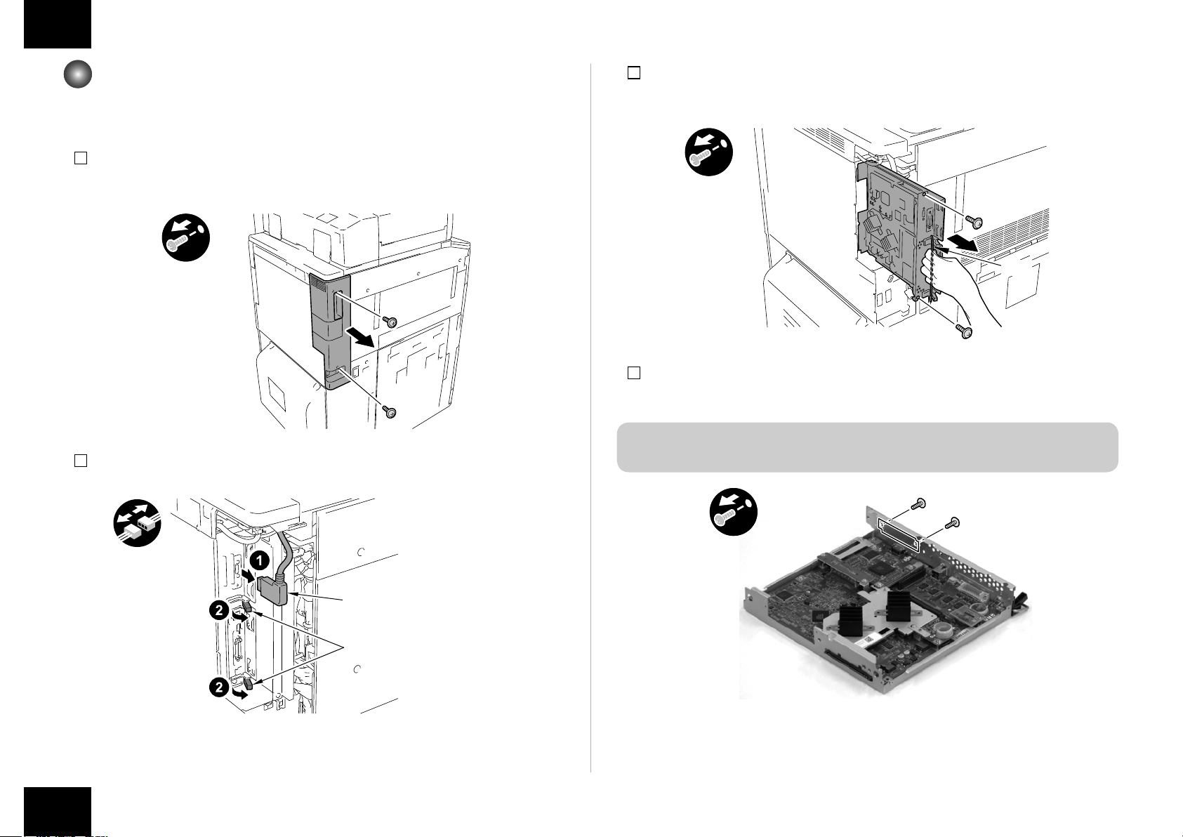
Installation Procedure > In the case iR-ADV C9280 PRO/C9270 PRO Series, iR-ADV C7280/C7270/C7260 Series > Installing the Open I/F PCB
In the case iR-ADV C9280 PRO/C9270 PRO Series,
iR-ADV C7280/C7270/C7260 Series
■Installing the Open I/F PCB
3) Hold the grip to remove Main Controller PCB 2.
• 2 screws (the removed screws are used in step 9.)
8
1) Remove the Box Left Cover.
• 2 Screws (the removed screws are used in step 12.)
x2
F-1-21
2) Disconnect the Reader Communication Cable and release the 2 Lock Levers.
x2
Grip
F-1-23
4) Remove the Face Cover. (Removed Face Cover is not used.)
• 2 Screws (the removed screws are used in step 7).)
NOTE:
Ask the user to store the Face Cover and Screws, in case it is needed in the future.
x2
Reader Communication Cable
Lock Lever
F-1-22
Installation Procedure > In the case iR-ADV C9280 PRO/C9270 PRO Series, iR-ADV C7280/C7270/C7260 Series > Installing the Open I/F PCB
F-1-24
8
Installation Procedure > In the case iR-ADV C9280 PRO/C9270 PRO Series, iR-ADV C7280/C7270/C7260 Series > Installing the Open I/F PCB
9
5) Remove the 2 screws. (the removed screws are used in step 7).)
x2
F-1-25
6) Remove the Bypass PCB. (Removed Bypass PCB is not used.)
• 2 Screws (the removed screws are used in step 7).)
• 1 Connector
NOTE:
Ask the user to store the Bypass PCB and Screws, in case it is needed in the future.
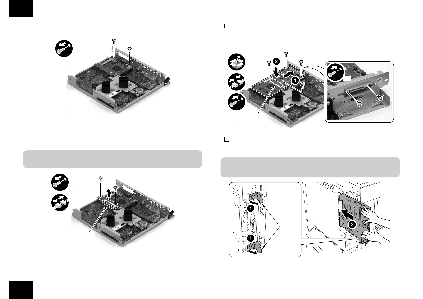
7) Install the Open I/F PCB.
• 1 Connector
• 6 Screws (the screws removed in step 4), 5) and 6).)
x2
x4
Connector
F-1-27
8) Release the 2 Lock Levers in the direction of the arrow and push the Main Controller PCB
2 with both hands until it stops.
CAUTION:
Be careful not to make the cables caught and install the Main Controller 2.
x2
Lock
Lever
Connector
F-1-26
Installation Procedure > In the case iR-ADV C9280 PRO/C9270 PRO Series, iR-ADV C7280/C7270/C7260 Series > Installing the Open I/F PCB
F-1-28
9
 Loading...