

Canon Color iR C3480, Color iR C2880, Color iR C2550, Color iR C3480i, Color iR C2550i Service Manual
...
SERVICE
MANUAL
CiRC3480/3480i/
3380/3080/3080i/
2880/2550/2550i/
DU7-1192-020
APRIL 2008
REV. 2
COPYRIGHT ©2008 CANON INC. CANON CiRC3480/3380/3080/2880/2550 Series REV. 2 PRINTED IN U.S.A.


Application
This manual has been issued by Canon Inc. for qualified persons to learn technical theory, installation, maintenance, and repair
of products. This manual covers all localities where the products are sold. For this reason, there may be information in this
manual that does not apply to your locality.
Corrections
This manual may contain technical inaccuracies or typographical errors due to improvements or changes in products. When
changes occur in applicable products or in the contents of this manual, Canon will release technical information as the need
arises. In the event of major changes in the contents of this manual over a long or short period, Canon will issue a new edition
of this manual.
The following paragraph does not apply to any countries where such provisions are inconsistent with local law.
Trademarks
The product names and company names used in this manual are the registered trademarks of the individual companies.
Copyright
This manual is copyrighted with all rights reserved. Under the copyright laws, this manual may not be copied, reproduced or
translated into another language, in whole or in part, without the written consent of Canon Inc.
COPYRIGHT © 2001 CANON INC.
Printed in Japan
Caution
Use of this manual should be strictly supervised to avoid disclosure of confidential information.
Symbols Used
This documentation uses the following symbols to indicate special information:
Symbol Description
Indicates an item of a non-specific nature, possibly classified as Note, Caution, or Warning.
Indicates an item requiring care to avoid electric shocks.
Indicates an item requiring care to avoid combustion (fire).
Indicates an item prohibiting disassembly to avoid electric shocks or problems.
Indicates an item requiring disconnection of the power plug from the electric outlet.
Indicates an item intended to provide notes assisting the understanding of the topic in question.
Memo
Introduction
REF.
Indicates an item of reference assisting the understanding of the topic in question.
Provides a description of a service mode.
Provides a description of the nature of an error indication.
i

Introduction
The following rules apply throughout this Service Manual:
1. Each chapter contains sections explaining the purpose of specific functions and the relationship between electrical and mechanical systems with reference to the timing of operation.
In the diagrams, represents the path of mechanical drive; where a signal name accompanies the symbol , the arrow indicates the
direction of the electric signal.
The expression "turn on the power" means flipping on the power switch, closing the front door, and closing the delivery unit door, which results in
supplying the machine with power.
2. In the digital circuits, '1'is used to indicate that the voltage level of a given signal is "High", while '0' is used to indicate "Low".(The voltage value,
however, differs from circuit to circuit.) In addition, the asterisk (*) as in "DRMD*" indicates that the DRMD signal goes on when '0'.
In practically all cases, the internal mechanisms of a microprocessor cannot be checked in the field. Theref ore, the operations of the microprocessors
used in the machines are not discussed: they are explained in terms of from sensors to the input of the DC controller PCB and from the output of the
DC controller PCB to the loads.
The descriptions in this Service Manual are subject to change without notice for product improvem ent or other purpo ses, and maj or changes will be communicated in the form of Service Information bulletins.
All service persons are expected to have a good understanding of the contents of this Service Manual and all relevant Service Information bulletins and be
able to identify and isolate faults in the machine."
ii

Contents
Contents
Chapter 1 Introduction
1.1 System Construction......................................................................................................................................1- 1
1.1.1 System Configuration Overview (Delivery Accessories)...................................................................1- 1
1.1.2 System Configuration 1 (Delivery Accessories)..................................................................................1- 1
1.1.3 System Configuration 2 (Delivery Accessories)..................................................................................1- 2
1.1.4 System Configuration 3 (Delivery Accessories)..................................................................................1- 4
1.1.5 System Configuration (Delivery Accessories).....................................................................................1- 5
1.1.6 System Configuration (Pickup/Original Processing Accessories)....................................................1- 7
1.1.7 System Configuration (Pickup/Original Processing Accessories)....................................................1- 9
1.1.8 Cassette Heater System Configuration 1..........................................................................................1- 10
1.1.9 System Configuration (Printing/Transmission Accessories) (USA)........................... ....................1- 10
1.1.10 System Configuration (Printing/Transmission Accessories).........................................................1- 11
1.1.11 Functions of Printing/Transmission Accessories (USA)................................................................ 1- 13
1.1.12 Functions of Printing/Transmission Accessories............................................................................1- 13
1.1.13 Other Options.......................................................................................................................................1- 14
1.2 Product Specifications .................................................................................................................................1- 14
1.2.1 Names of Parts.......................................................................................................................................1- 14
1.2.1.1 External View...................................................................................................................................1- 14
1.2.1.2 Cross Section.................................................................................................................................. 1- 16
1.2.2 Using the Machine .................................................................................................................................1- 17
1.2.2.1 Turning On the Power Switch................................................................................... ....................1- 17
1.2.2.2 Points to Note About Turning Off the Main Power Switch .......................... .............................1- 17
1.2.3 User Mode Items....................................................................................................................................1- 19
1.2.3.1 Common Settings..................................................................... ....................................... ...............1- 19
1.2.3.2 Common Settings..................................................................... ....................................... ...............1- 22
1.2.3.3 Timer Settings ................................................................................................................................. 1- 24
1.2.3.4 Adjustment/Cleaning.................................................. ....................................... .............................1- 24
1.2.3.5 Adjustment/Cleaning.................................................. ....................................... .............................1- 24
1.2.3.6 Report Settings ...............................................................................................................................1- 25
1.2.3.7 System Settings..............................................................................................................................1- 25
1.2.3.8 System Settings..............................................................................................................................1- 29
1.2.3.9 Copy Settings.................................................................................................................................. 1- 31
1.2.3.10 Communications Settings .............................................................. ........................................ ...... 1- 31
1.2.3.11 Communications Settings .............................................................. ........................................ ...... 1- 33
1.2.3.12 Mail Box Settings............................................. .............................................................................1- 34
1.2.3.13 Address Book Settings............................................. ....................................... .............................1- 34
1.2.4 User Maintenance.................................................................................................................................. 1- 36
1.2.4.1 Cleaning...........................................................................................................................................1- 36
1.2.4.2 Inspection......................................................................................................................................... 1- 40
1.2.5 Safety.......................................................................................................................................................1- 42
1.2.5.1 Laser safety.....................................................................................................................................1- 42
1.2.5.2 CDRH Act.........................................................................................................................................1- 42
1.2.5.3 Handling of laser system..................................... ....................................... ...................................1- 42

Contents
1.2.5.4 Safety of Toner................................................................................................................................1- 43
1.2.5.5 Notes when handling a lithium battery........................................................................................ 1- 43
1.2.5.6 Notes before it works serving ....................................................................................................... 1- 44
1.2.6 Product Specifications...........................................................................................................................1- 44
1.2.6.1 Type and function ...........................................................................................................................1- 44
1.2.6.2 Type and function ...........................................................................................................................1- 45
1.2.6.3 Others............................................................................................................................................... 1- 45
1.2.6.4 Others............................................................................................................................................... 1- 46
1.2.7 Function List............................................................................................................................................ 1- 46
1.2.7.1 Print speed (image)........................................................................................................................ 1- 46
1.2.7.2 Print speed (image)........................................................................................................................ 1- 47
1.2.7.3 Type of paper..................................................................................................................................1- 48
1.2.7.4 Type of paper..................................................................................................................................1- 49
Chapter 2 Installation
2.1 Making Pre-Checks........................................................................................................................................2- 1
2.1.1 Selecting the Site of Installation............................................................................................................2- 1
2.1.2 Check to Make Before Installation........................................................................................................ 2- 2
2.1.3 Combination Table of Accessory Installation...................................................................................... 2- 2
2.1.4 Checking the Contents............................................................................................................................2- 4
2.2 Unpacking and Installation............................................................................................................................2- 6
2.2.1 Unpacking.................................................................................................................................................2- 6
2.2.2 Installation of the Scanner......................................................................................................................2- 6
2.2.3 Installation of the Drum Unit...................................................................................................................2- 6
2.2.4 Installation of the Toner Retainer........................................................................................................2- 11
2.2.5 Connection of the Cable.......................................................................................................................2- 12
2.2.6 Points to Note When Turning Off the Main Power ...........................................................................2- 12
2.2.7 Attaching Other Parts............................................................................................................................2- 12
2.2.8 Fixing the Machine in Place................................................................................................................. 2- 14
2.2.9 Setting Up the Cassette........................................................................................................................2- 14
2.2.10 Automatic Gradation Correction........................................................................................................2- 14
2.2.11 Adjusting the Image Position.............................................................................................................2- 15
2.3 Checking the Connection to the Network................................................................................................. 2- 18
2.3.1 Checking the Connection to the Network..........................................................................................2- 18
2.3.2 Using PING............................................................................................................................................. 2- 18
2.3.3 Making Checks Using a Remote Host Address................................................................................2- 18
2.4 Troubleshooting the Network......................................................................................................................2- 18
2.4.1 Troubleshooting the Network...............................................................................................................2- 18
2.4.2 Making Checks Using a Loopback Address...................................................................................... 2- 18
2.4.3 Making a Check Using a Local Host Address................................................................................... 2- 18
2.5 Checking the Images/Operations............................................................................................................... 2- 19
2.5.1 Checking the Images ............................................................................................................................ 2- 19
2.6 Relocating the Machine............................................................................................................................... 2- 19
2.6.1 Relocating the Machine........................................................................................................................2- 19
2.7 Installing the Copy Tray............................................................................................................................... 2- 19
2.7.1 Checking the Components...................................................................................................................2- 19
2.7.2 Turning Off the Machine.......................................................................................................................2- 19
2.7.3 Installation Procedure ...........................................................................................................................2- 19

Contents
2.8 Installing the Card Reader...........................................................................................................................2- 20
2.8.1 Points to Note at Installation.................................................................................................................2- 20
2.8.2 Checking the Contents..........................................................................................................................2- 20
2.8.3 Turning Off the Machine........................................................................................................................2- 20
2.8.4 Installation Procedure............................................................................................................................2- 20
2.8.5 Installation Procedure in the imageWARE Accounting Manager (hereinafter referred to iWAM)
Environment.................................................................................................................................................2- 22
2.9 Installing the Original Tray...........................................................................................................................2- 23
2.9.1 Checking the Content............................................................................................................................2- 23
2.9.2 Installation Procedure............................................................................................................................2- 23
2.10 Installing the Key Switch Unit....................................................................................................................2- 24
2.10.1 Checking the Contents........................................................................................................................2- 24
2.10.2 Turning Off the Machine......................................................................................................................2- 24
2.10.3 Installation Procedure..........................................................................................................................2- 24
2.10.4 Checking After Installation..................................................................................................................2- 25
2.11 Installing the Voice Guidance Kit..............................................................................................................2- 25
2.11.1 Checking the Contents........................................................................................................................2- 25
2.11.2 Turning Off the Host Machine ............................................................................................................2- 26
2.11.3 Installation Procedure..........................................................................................................................2- 26
2.12 Installing the Voice Operation Kit..............................................................................................................2- 30
2.12.1 Checking the Contents........................................................................................................................2- 30
2.12.2 Turning Off the Host Machine ............................................................................................................2- 31
2.12.3 Installation Procedure..........................................................................................................................2- 31
2.13 Installing the Wireless Network Interface Adapter.................................................................................2- 38
2.13.1 Points to Note at Installation...............................................................................................................2- 38
2.13.2 Checking the Contents........................................................................................................................2- 38
2.13.3 Turning Off the Host Machine ............................................................................................................2- 39
2.13.4 Installation Procedure..........................................................................................................................2- 39
2.13.5 Affixing the Label..................................................................................................................................2- 42
2.14 Installing the DADF.....................................................................................................................................2- 42
2.14.1 Checking the Contents........................................................................................................................2- 42
2.14.2 Turning Off the Host Machine ............................................................................................................2- 42
2.14.3 Installation Procedure..........................................................................................................................2- 42
2.14.4 Cleaning the Copyboard Glass..........................................................................................................2- 44
2.14.5 Adjustment.............................................................................................................................................2- 44
2.14.6 Affixing Labels.......................................................................................................................................2- 47
2.14.7 Operation Check...................................................................................................................................2- 47
2.15 Installing the Inner 2 Way Tray .................................................................................................................2- 47
2.15.1 Checking the Components..................................................................................................................2- 47
2.15.2 Turning Off the Host Machine ............................................................................................................2- 48
2.15.3 Installation Procedure..........................................................................................................................2- 48
2.16 Installing the Serial Interface Kit ...............................................................................................................2- 48
2.16.1 Points to Note About Installation........................................................................................................2- 48
2.16.2 Checking the Contents........................................................................................................................2- 48
2.16.3 Turning Off the Host Machine ............................................................................................................2- 49
2.16.4 Installation Procedure..........................................................................................................................2- 49

Contents
Chapter 3 Basic Operation
3.1 Construction.....................................................................................................................................................3- 1
3.1.1 Functional Construction..........................................................................................................................3- 1
3.1.2 Connections Among Major PCBs..........................................................................................................3- 2
3.2 Basic Sequence..............................................................................................................................................3- 3
3.2.1 Basic Sequence of Operations at Power-On ...................................................................................... 3- 3
3.2.2 Basic Sequence of Operations for a Print Job (full color).................................................................3- 3
3.2.3 Basic Sequence of Operations for a Print Job (mono color)............................................................ 3- 4
Chapter 4 Main Controller
4.1 Construction.....................................................................................................................................................4- 1
4.1.1 Construction and Functions...................................................................................................................4- 1
4.2 Construction of the Electrical Circuitry........................................................................................................4- 2
4.2.1 Main Controller PCB (main)...................................................................................................................4- 2
4.2.2 SRAM PCB...............................................................................................................................................4- 2
4.3 Start-Up Sequence.........................................................................................................................................4- 4
4.3.1 Overview ...................................................................................................................................................4- 4
4.3.2 Start-Up Sequence..................................................................................................................................4- 4
4.4 Actions when HDD Error ............................................................................................................................... 4- 7
4.4.1 E602 in Detail...........................................................................................................................................4- 7
4.5 Image Processing.........................................................................................................................................4- 11
4.5.1 Overview of the Flow of Image Data ..................................................................................................4- 11
4.5.2 Reader Input Image Processing..........................................................................................................4- 11
4.5.3 Printer Output Image Processing........................................................................................................4- 13
4.5.4 Compression, Decompression, and Edit Processing Blocks..........................................................4- 14
4.6 Flow of Image Data...................................................................................................................................... 4- 14
4.6.1 Flow of Image Data for Copier Functions.......................................................................................... 4- 14
4.6.2 Flow of Image Data for Box Functions............................................................................................... 4- 15
4.6.3 Flow of Image Data for SEND Functions...........................................................................................4- 15
4.6.4 Flow of Image Data for Fax Transmission Functions......................................................................4- 16
4.6.5 Flow of Image Data for Fax Reception Functions............................................................................ 4- 16
4.6.6 Flow of Image Data for PDL Functions..............................................................................................4- 17
4.7 Parts Replacement Procedure ...................................................................................................................4- 18
4.7.1 Controller Box.........................................................................................................................................4- 18
4.7.1.1 Before Removing the Main Controller Box ................................................................................. 4- 18
4.7.1.2 Removing the Controller Box........................................................................................................ 4- 18
4.7.2 Main Controller PCB (main)..................................................................................................................4- 18
4.7.2.1 Before Removing the Main Controller PCB................................................................................4- 18
4.7.2.2 Removing the Main Controller PCB.............................................................................................4- 18
4.7.2.3 Replacing Main Controller PCB ...................................................................................................4- 19
4.7.3 Main Controller PCB (sub R-A)............................................................................................................ 4- 19
4.7.3.1 Before Removing the Main Controller PCB (sub-R-A) .............................................................4- 19
4.7.3.2 Removing the Main Controller PCB (sub-R-A)..........................................................................4- 19
4.7.4 Main Controller PCB (sub PDRM-A)...................................................................................................4- 19
4.7.4.1 Before Removing the Main Controller PCB (sub-PDRAM-A).................................................. 4- 19
4.7.4.2 Removing the Main Controller PCB (sub-PDRAM-A)............................................................... 4- 19
4.7.5 Main Controller PCB (sub SJ-A)..........................................................................................................4- 20
4.7.5.1 Before Removing the Main Controller PCB (sub SJ-A)............................................................4- 20
4.7.5.2 Removing the Main Controller PCB (sub SJ-A).........................................................................4- 20

Contents
4.7.6 Main Controller PCB (sub LAN-A)........................................................................................................4- 20
4.7.6.1 Before Removing the Main Controller PCB (sub LANBAR-C).................................................4- 20
4.7.6.2 Removing the Main Controller PCB (sub LANBAR-C)..............................................................4- 20
4.7.7 Main Controller PCB (sub RB-A)..........................................................................................................4- 21
4.7.7.1 Before Removing the Main Controller PCB (sub RB-A2) .........................................................4- 21
4.7.7.2 Removing the Main Controller PCB (sub RB-A2) ......................................................................4- 21
4.7.8 SRAM PCB ..............................................................................................................................................4- 21
4.7.8.1 Before Removing the SRAM .........................................................................................................4- 21
4.7.8.2 Removing the SRAM ......................................................................................................................4- 22
4.7.8.3 When Replacing the SRAM PCB..................................................................................................4- 22
4.7.9 Boot ROM PCB.......................................................................................................................................4- 22
4.7.9.1 Before Removing the Boot ROM PCB.........................................................................................4- 22
4.7.9.2 Removing the Boot ROM PCB......................................................................................................4- 22
4.7.10 Image Memory (SDRAM)....................................................................................................................4- 22
4.7.10.1 Before Removing the Image Memory (SDRAM) PCB.............................................................4- 22
4.7.10.2 Removing the Image Memory (SDRAM) PCB..........................................................................4- 22
4.7.11 HDD.........................................................................................................................................................4- 23
4.7.11.1 Before Removing the HDD ..........................................................................................................4- 23
4.7.11.2 Removing the HDD.......................................................................................................................4- 23
4.7.11.3 When Replacing the HDD............................................................................................................4- 23
4.7.12 Controller Fan........................................................................................................................................4- 24
4.7.12.1 Before Removing the Controller Fan..........................................................................................4- 24
4.7.12.2 Removing the Controller Fan.......................................................................................................4- 24
Chapter 5 Original Exposure System
5.1 Construction.....................................................................................................................................................5- 1
5.1.1 Specifications, Control Mechanisms, and Functions..........................................................................5- 1
5.1.2 Major Components...................................................................................................................................5- 1
5.1.3 Construction of the Control System.......................................................................................................5- 2
5.1.4 Reader Controller PCB............................................................................................................................5- 4
5.2 Basic Sequence...............................................................................................................................................5- 5
5.2.1 Basic Sequence of Operations at Power-On.......................................................................................5- 5
5.2.2 Basic Sequence of Operations in Response to a Press on the Start Key (book mode, 1 original). .
5- 5
5.2.3 Basic Sequence of Operations in Response to a Press on the Start Key (ADF mode, 1 original)56
5.3 Various Control Mechanisms.........................................................................................................................5- 7
5.3.1 Controlling the Scanner Drive System...................................................................................................5- 7
5.3.1.1 Overview.............................................................................................................................................5- 7
5.3.1.2 Reader Motor Control .......................................................................................................................5- 7
5.3.2 Contact Image Sensor (CIS)...................................................................................................................5- 9
5.3.2.1 Overview.............................................................................................................................................5- 9
5.3.2.2 Analog Control Inside the Contact Image Sensor (CIS) ...........................................................5- 10
5.3.3 Enlargement/Reduction .........................................................................................................................5- 10
5.3.3.1 Changing the Magnification in Main Scanning Direction...........................................................5- 10
5.3.3.2 Changing the Magnification in Sub Scanning Direction............................................................5- 10
5.3.4 Controlling the Scanning Lamp.............................................................................................................5- 11
5.3.4.1 Scanning Lamp................................................................................................................................5- 11

Contents
5.3.4.2 Overview..........................................................................................................................................5- 11
5.3.4.3 Activation Control............................................................................................................................5- 11
5.3.4.4 Error Detection................................................................................................................................5- 11
5.3.5 Detecting the Size of Originals............................................................................................................. 5- 11
5.3.5.1 Overview..........................................................................................................................................5- 11
5.3.5.2 Points of Original Size Detection..................................................................................................5- 13
5.3.5.3 Overview of Detection Operation ................................................................................................. 5- 13
5.3.6 Dirt Sensor Control.................................................................................................................................5- 15
5.3.6.1 Overview..........................................................................................................................................5- 15
5.3.7 Image Processing...................................................................................................................................5- 17
5.3.7.1 Overview..........................................................................................................................................5- 17
5.3.7.2 Driving the CCD..............................................................................................................................5- 18
5.3.7.3 Gain Correction and Offset Correction for the CCD Output.....................................................5- 18
5.3.7.4 A/D Conversion of the CCD Output.............................................................................................5- 18
5.3.7.5 Shading Correction (outline).........................................................................................................5- 19
5.3.7.6 Shading Adjustment .......................................................................................................................5- 19
5.3.7.7 Shading Correction.........................................................................................................................5- 19
5.4 Parts Replacement Procedure ...................................................................................................................5- 20
5.4.1 Copyboard Glass.................................................................................................................................... 5- 20
5.4.1.1 Removing the Copyboard Glass..................................................................................................5- 20
5.4.1.2 After Replacing the Copyboard Glass.........................................................................................5- 20
5.4.1.3 Removing the ADF Reading Glass..............................................................................................5- 21
5.4.1.4 After Replacing the ADF Reading Glass.....................................................................................5- 21
5.4.2 Reader Controller PCB.......................................................................................................................... 5- 22
5.4.2.1 Before Replacing the Reader Controller PCB............................................................................5- 22
5.4.2.2 Before Removing the Reader Controller PCB ...........................................................................5- 22
5.4.2.3 Removing the Reader Controller PCB........................................................................................5- 22
5.4.2.4 After Replacing the Reader Controller PCB...............................................................................5- 23
5.4.3 Inverter PCB............................................................................................................................................ 5- 24
5.4.3.1 Before Removing the Inverter PCB .............................................................................................5- 24
5.4.3.2 Removing the Inverter PCB..........................................................................................................5- 24
5.4.4 Scanner Motor........................................................................................................................................5- 25
5.4.4.1 Before Removing the Scanner Motor..........................................................................................5- 25
5.4.4.2 Removing the Scanner Motor....................................................................................................... 5- 25
5.4.5 Contact Sensor.......................................................................................................................................5- 25
5.4.5.1 Before Removing the Contact Image Sensor (CIS)..................................................................5- 25
5.4.5.2 Removing the Contact Image Sensor (CIS)...............................................................................5- 25
5.4.5.3 After Replacing the CIS.................................................................................................................5- 26
5.4.6 Original Cover Sensor...........................................................................................................................5- 26
5.4.6.1 Before Removing the Copyboard Cover Open/Closed Sensor (front/rear)...........................5- 26
5.4.6.2 Removing the Copyboard Cover Open/Closed Sensor (front/rear)........................................ 5- 26
5.4.7 Contact Sensor HP Sensor...................................................................................................................5- 27
5.4.7.1 Before Removing the Contact Sensor HP Sensor....................................................................5- 27
5.4.7.2 Removing the Contract Sensor Home Position Sensor ...........................................................5- 27
5.4.8 Original Sensor.......................................................................................................................................5- 27
5.4.8.1 Before Removing the Original Size Sensor (AB/Inchconfiguration)....................................... 5- 27
5.4.8.2 Removing the Original Size Sensor (AB/Inch-configuration)................................................... 5- 27

Contents
Chapter 6 Laser Exposure
6.1 Construction.....................................................................................................................................................6- 1
6.1.1 Specifications, Control Mechanisms, and Functions..........................................................................6- 1
6.1.2 Overview....................................................................................................................................................6- 1
6.2 Various Control................................................................................................................................................6- 3
6.2.1 Controlling the Laser Activation Timing.................................................................................................6- 3
6.2.1.1 Turning On and Off the Laser Light................................................................................................6- 3
6.2.1.2 Controlling Synchronization in Main Scanning Direction ............................................................6- 4
6.2.1.3 Controlling Synchronization in Sub Scanning Direction..............................................................6- 5
6.2.1.4 BD Correction.....................................................................................................................................6- 7
6.2.2 Controlling the Intensity of Laser Light..................................................................................................6- 9
6.2.2.1 APC Control .......................................................................................................................................6- 9
6.2.3 Controlling the Laser Scanner Motor...................................................................................................6- 10
6.2.3.1 Controlling the Speed of the Laser Scanner Motor....................................................................6- 10
6.3 Parts Replacement Procedure....................................................................................................................6- 12
6.3.1 Laser Scanner Unit.................................................................................................................................6- 12
6.3.1.1 Before Removing the Laser Scanner Unit...................................................................................6- 12
6.3.1.2 Removing the Laser Scanner Unit................................................................................................6- 12
6.3.1.3 After Replacing the Laser Scanner Unit......................................................................................6- 13
Chapter 7 Image Formation
7.1 Construction.....................................................................................................................................................7- 1
7.1.1 Specifications, Control Mechanisms, and Functions..........................................................................7- 1
7.1.2 Overview....................................................................................................................................................7- 2
7.1.3 Printing Process........................................................................................................................................7- 3
7.1.4 Static Image Formation Block ................................................................................................................7- 4
7.1.5 Developing Block......................................................................................................................................7- 6
7.1.6 Transfer Block...........................................................................................................................................7- 7
7.1.7 Fixing Block...............................................................................................................................................7- 8
7.1.8 ITB Cleaning Block...................................................................................................................................7- 9
7.1.9 Photosensitive Drum Cleaning Block....................................................................................................7- 9
7.2 Driving and Controlling the High-Voltage System....................................................................................7- 10
7.2.1 Overview..................................................................................................................................................7- 10
7.2.2 Generation of the Primary Charging Bias...........................................................................................7- 11
7.2.3 Generation of the Developing Bias......................................................................................................7- 11
7.2.4 Generation of the Primary Transfer Bias............................................................................................7- 12
7.2.5 Generation of the Secondary Transfer Bias.......................................................................................7- 12
7.3 Image Stabilization Control..........................................................................................................................7- 12
7.3.1 Overview of Image Stabilization...........................................................................................................7- 12
7.3.2 Timing of Image Stabilization Control .................................................................................................7- 13
7.3.3 Drum Film Thickness Detection...........................................................................................................7- 14
7.3.4 ATR Control.............................................................................................................................................7- 15
7.3.5 D-max Control.........................................................................................................................................7- 16
7.3.6 PASCAL Control.....................................................................................................................................7- 19
7.3.7 D-half Control..........................................................................................................................................7- 20
7.3.8 ARCDAT Control....................................................................................................................................7- 23
7.3.9 Color Displacement Correction Control..............................................................................................7- 25

Contents
7.3.10 ATVC Control .......................................................................................................................................7- 28
7.4 Special Control..............................................................................................................................................7- 29
7.4.1 Black band sequence............................................................................................................................7- 29
7.4.2 OHP black band sequence.................................................................................................................. 7- 30
7.4.3 Colour band sequence..........................................................................................................................7- 30
7.5 Drum Unit.......................................................................................................................................................7- 32
7.5.1 Drum Unit.................................................................................................................................................7- 32
7.5.1.1 Overview..........................................................................................................................................7- 32
7.5.1.2 Detecting the Presence/Absence of the Drum Unit................................................................... 7- 33
7.5.1.3 Identifying a New/Old Drum Unit.................................................................................................. 7- 33
7.5.1.4 Opening/Closing the Toner Shutter............................................................................................. 7- 35
7.6 Toner Container............................................................................................................................................7- 36
7.6.1 Overview .................................................................................................................................................7- 36
7.6.2 Supplying Toner.....................................................................................................................................7- 36
7.6.3 Detecting the Level of Toner................................................................................................................7- 38
7.6.4 Toner Container Detection...................................................................................................................7- 39
7.7 Transfer Unit..................................................................................................................................................7- 39
7.7.1 Outline of the Transfer Unit................................................................................................................... 7- 39
7.7.1.1 Overview..........................................................................................................................................7- 39
7.7.1.2 Primary Transfer Block..................................................................................................................7- 40
7.7.1.3 ITB Soiling Removal Sequence Control...................................................................................... 7- 40
7.7.1.4 Secondary Transfer Block.............................................................................................................7- 41
7.8 Waste Toner Collection Mechanism..........................................................................................................7- 42
7.8.1 Collecting the Waste Toner..................................................................................................................7- 42
7.8.2 Detecting the Level of Waste Toner...................................................................................................7- 43
7.8.3 Waste toner case detection.................................................................................................................. 7- 44
7.9 Parts Replacement Procedure ...................................................................................................................7- 45
7.9.1 Process Unit............................................................................................................................................7- 45
7.9.1.1 Removing the Process Unit...........................................................................................................7- 45
7.9.2 Drum Unit.................................................................................................................................................7- 46
7.9.2.1 Removing the Drum Cartridge......................................................................................................7- 46
7.9.3 Drum ITB Motor......................................................................................................................................7- 47
7.9.3.1 Before Removing the Drum ITB Moto.........................................................................................7- 47
7.9.3.2 Removing the Drum ITB Motor..................................................................................................... 7- 47
7.9.4 Hopper Assembly...................................................................................................................................7- 48
7.9.4.1 Before Removing the Hopper Supply Unit.................................................................................. 7- 48
7.9.4.2 Removing the Hopper Supply Unit...............................................................................................7- 48
7.9.5 Developing Motor (Bk/Y/M/C)............................................................................................................... 7- 49
7.9.5.1 Before Removing the Developing Motor.....................................................................................7- 49
7.9.5.2 Removing the Developing Motor.................................................................................................. 7- 49
7.9.6 Intermediate Transfer Unit....................................................................................................................7- 49
7.9.6.1 Removing the ITB Unit...................................................................................................................7- 49
7.9.7 Transfer Cleaning Unit........................................................................................................................... 7- 51
7.9.7.1 Before Removing the Transfer Cleaner Unit.............................................................................. 7- 51
7.9.7.2 Removing the Transfer Cleaner Unit...........................................................................................7- 51
7.9.7.3 Points to Note When Replacing the Transfer Cleaner Unit.....................................................7- 52
7.9.8 Secondary Transfer External Roller.................................................................................................... 7- 52
7.9.8.1 Removing the Secondary Transfer Outer Roller .......................................................................7- 52
7.9.8.2 After Replacing the Secondary Transfer Roller.........................................................................7- 53

Contents
Chapter 8 Pickup/Feeding System
8.1 Construction.....................................................................................................................................................8- 1
8.1.1 Specifications, Controls, and Functions................................................................................................8- 1
8.1.2 Division into Blocks..................................................................................................................................8- 3
8.1.3 Arrangement of Rollers............................................................................................................................8- 4
8.1.4 Diagram of Paper Paths (w/ copy tray )................................................................................................8- 6
8.1.5 Diagram of Paper Paths (w/ Finisher-Z1/copy tray)............................................................................8- 7
8.1.6 Diagram of Paper Paths (w/ Finisher-Y1/Saddle Finisher-Y2)..........................................................8- 7
8.1.7 Arrangement of Sensors .........................................................................................................................8- 8
8.1.8 Route of Drive.........................................................................................................................................8- 10
8.2 Basic Sequence.............................................................................................................................................8- 11
8.2.1 Basic Sequence......................................................................................................................................8- 11
8.3 Controlling the Feeding Speed....................................................................................................................8- 11
8.3.1 Increase in Speed ..................................................................................................................................8- 11
8.3.2 Feeding Speed According to the Print Media and Re solu tio n .......................................................8- 13
8.3.3 Feeding Speed of Each Feeding Path and Timing for Switching Feeding Speed ......................8- 13
8.3.4 Reversing Accelerating Control of Large Size Paper.......................................................................8- 16
8.4 Detecting Jams..............................................................................................................................................8- 16
8.4.1 Delay Jams ..............................................................................................................................................8- 16
8.4.1.1 Delay Jam for Those Other Than the Pickup Unit .....................................................................8- 16
8.4.1.2 Delay Jam for the Pickup Unit.......................................................................................................8- 18
8.4.2 Stationary Jams.......................................................................................................................................8- 18
8.4.2.1 Common Stationary Jam................................................................................................................8- 18
8.4.2.2 Stationary Jam at Power-On .........................................................................................................8- 18
8.4.3 Other Jams...............................................................................................................................................8- 20
8.4.3.1 Size Difference Jam........................................................................................................................8- 20
8.4.3.2 Material Difference Jam.................................................................................................................8- 20
8.4.3.3 Door Open Jam ...............................................................................................................................8- 20
8.5 Cassette Pick-Up Unit...................................................................................................................................8- 20
8.5.1 Overview..................................................................................................................................................8- 20
8.5.2 Basic Sequence .....................................................................................................................................8- 22
8.5.3 Identifying the Paper Size.....................................................................................................................8- 22
8.5.4 Setting Up the Universal Cassette.......................................................................................................8- 24
8.5.5 Paper Level Sensor................................................................................................................................8- 24
8.6 Manual Feed Pickup Unit.............................................................................................................................8- 26
8.6.1 Overview..................................................................................................................................................8- 26
8.6.2 Basic Sequence of Operation...............................................................................................................8- 28
8.6.3 Identifying the Paper Size.....................................................................................................................8- 29
8.7 Registration Unit............................................................................................................................................8- 29
8.7.1 Overview..................................................................................................................................................8- 29
8.7.2 Control of Registration Unit ..................................................................................................................8- 30
8.7.3 Checking Horizontal Registration........................................................................................................8- 30
8.7.4 Material Difference Jam Detection .....................................................................................................8- 31
8.8 Pre-Fixing Feeding........................................................................................................................................8- 31
8.8.1 Fixing Arch Control.................................................................................................................................8- 31
8.9 Duplex Feeding Unit .....................................................................................................................................8- 33
8.9.1 Overview..................................................................................................................................................8- 33
8.9.2 The Number of Circulating Sheets at Duplexing Feeding................................................................8- 34

Contents
8.9.3 Duplexing Re-Pickup Control...............................................................................................................8- 34
8.9.4 Sequence of Image Formation............................................................................................................8- 34
8.9.5 Flow of Paper ........................................................................................................................................8- 35
8.10 Delivery.........................................................................................................................................................8- 40
8.10.1 Delivery Control.................................................................................................................................... 8- 40
8.10.2 Delivery to the Main Body Tray.........................................................................................................8- 40
8.10.3 Delivery Operation when Mounting the Delivery Accessory.........................................................8- 40
8.10.4 Specifying the Delivery Point.............................................................................................................8- 41
8.11 Parts Replacement Procedure.................................................................................................................8- 42
8.11.1 Pickup Unit 1.........................................................................................................................................8- 42
8.11.1.1 Before Removing the Cassette Pickup Unit 1..........................................................................8- 42
8.11.1.2 Removing the Cassette Pickup Unit 1.......................................................................................8- 42
8.11.2 Pickup Unit 2.........................................................................................................................................8- 42
8.11.2.1 Before Removing the Cassette Pickup Unit 2..........................................................................8- 42
8.11.2.2 Removing the Cassette Pickup Unit 2.......................................................................................8- 42
8.11.3 Sensor Mounting Plate........................................................................................................................8- 42
8.11.3.1 Before Removing the Sensor Mounting Plate..........................................................................8- 42
8.11.3.2 Removing the Sensor Mounting Plate.......................................................................................8- 43
8.11.4 Pickup Roller.........................................................................................................................................8- 43
8.11.4.1 Removing the Pickup Roller........................................................................................................8- 43
8.11.5 Feed Roller............................................................................................................................................8- 44
8.11.5.1 Removing the Feed Roller...........................................................................................................8- 44
8.11.6 Separation Roller..................................................................................................................................8- 44
8.11.6.1 Removing the Separation Roller ................................................................................................ 8- 44
8.11.7 Cassette Pickup Motor 1.....................................................................................................................8- 44
8.11.7.1 Before Removing the Cassette Pickup Motor 1....................................................................... 8- 44
8.11.7.2 Removing the Cassette Pickup Motor 1....................................................................................8- 44
8.11.8 Cassette Pickup Motor 2.....................................................................................................................8- 45
8.11.8.1 Before Removing the Cassette Pickup Motor 2....................................................................... 8- 45
8.11.8.2 Removing the Cassette Pickup Motor 2....................................................................................8- 45
8.11.9 Cassette Size Detection Sensor........................................................................................................8- 46
8.11.9.1 Before Removing the Cassette Size Sensor............................................................................8- 46
8.11.9.2 Removing Cassette Size Sensor ..............................................................................................8- 46
8.11.10 Cassette Retry Paper Sensor...........................................................................................................8- 47
8.11.10.1 Before Removing Cassette Retry Paper Sensor .................................................................. 8- 47
8.11.10.2 Removing Cassette Retry Paper Sensor ...............................................................................8- 47
8.11.11 Cassette Paper Sensor .....................................................................................................................8- 47
8.11.11.1 Before Removing Cassette Paper Sensor.............................................................................. 8- 47
8.11.11.2 Removing Cassette Paper Sensor .........................................................................................8- 47
8.11.12 Cassette Paper Level Sensor (A/B)................................................................................................8- 48
8.11.12.1 Before Removing Cassette Paper Level Sensor (A/B) ........................................................8- 48
8.11.12.2 Removing Cassette Paper Level Sensor (A/B) .....................................................................8- 48
8.11.13 Slide Resistor......................................................................................................................................8- 48
8.11.13.1 Before Removing Slide Resistor..............................................................................................8- 48
8.11.13.2 Removing Slide Resistor ..........................................................................................................8- 48
8.11.14 Cassette Pickup Solenoid.................................................................................................................8- 48
8.11.14.1 Before Removing Cassette Pickup Solenoid ......................................................................... 8- 48
8.11.14.2 Removing Cassette Pickup Solenoid ......................................................................................8- 48
8.11.15 Cassette Size Sensor Relay PCB ................................................................................................... 8- 49

Contents
8.11.15.1 Before Removing Cassette Size Sensor PCB........................................................................8- 49
8.11.15.2 Removing Cassette Size Sensor PCB.....................................................................................8- 49
8.11.16 Manual Feed Pickup Clutch..............................................................................................................8- 49
8.11.16.1 Before Removing Manual Feed Pickup Clutch.......................................................................8- 49
8.11.16.2 Removing Manual Feed Pickup Clutch ...................................................................................8- 49
8.11.17 Manual Feed Tray Unit.......................................................................................................................8- 50
8.11.17.1 Before Removing Manual Feed Tray Unit ..............................................................................8- 50
8.11.17.2 Removing Manual Feed Tray Unit............................................................................................8- 50
8.11.18 Manual Feed Unit................................................................................................................................8- 50
8.11.18.1 Before Removing Manual Feed Unit .......................................................................................8- 50
8.11.18.2 Removing Manual Feed Unit.....................................................................................................8- 50
8.11.19 Manual Pickup Roller .........................................................................................................................8- 51
8.11.19.1 Before Removing Manual Feed Pickup Roller........................................................................8- 51
8.11.19.2 Removing Manual Feed Pickup Roller.....................................................................................8- 51
8.11.20 Manual Feed Separation Pad...........................................................................................................8- 52
8.11.20.1 Before Removing Manual Feed Separation Pad ...................................................................8- 52
8.11.20.2 Removing Manual Feed Pickup Separation Pad ...................................................................8- 52
8.11.21 Registration Motor...............................................................................................................................8- 52
8.11.21.1 Before Removing Registration Motor ......................................................................................8- 52
8.11.21.2 Removing Registration Motor....................................................................................................8- 52
8.11.22 Duplex Unit...........................................................................................................................................8- 52
8.11.22.1 Before Removing Duplexing Feed frame ...............................................................................8- 52
8.11.22.2 Removing Duplexing Feed frame ............................................................................................8- 52
8.11.23 Duplex Feed Sensor...........................................................................................................................8- 53
8.11.23.1 Before Removing Duplexing Feed Sensor .............................................................................8- 53
8.11.23.2 Removing Duplexing Feed Sensor...........................................................................................8- 53
Chapter 9 Fixing System
9.1 Construction.....................................................................................................................................................9- 1
9.1.1 Specifications, Controls, and Functions................................................................................................9- 1
9.1.2 Major Components...................................................................................................................................9- 1
9.1.3 Construction of the Control System.......................................................................................................9- 2
9.2 Various Control Mechanisms.........................................................................................................................9- 3
9.2.1 Controlling the Fixing Temperature........................................................................................................9- 3
9.2.1.1 Overview.............................................................................................................................................9- 3
9.2.1.2 Temperature control in standby......................................................................................................9- 3
9.2.1.3 Temperature Control during Printing..............................................................................................9- 4
9.2.1.4 Fixing film edge cooling control.......................................................................................................9- 6
9.2.1.5 Detection of the Fixing Assembly Absence/Presence.................................................................9- 9
9.2.2 Down Sequence Control........................................................................................................................9- 10
9.2.2.1 Down Sequence Control ................................................................................................................9- 10
9.3 Film Unit Pressurizing Mechanism............................................................................................................9- 11
9.3.1 Pressure/release control .......................................................................................................................9- 11
9.4 Protective Functions .....................................................................................................................................9- 11
9.4.1 Overview..................................................................................................................................................9- 11
9.4.2 Fixing System Error Code.....................................................................................................................9- 13
9.5 Parts Replacement Procedure....................................................................................................................9- 14
9.5.1 Fixing Unit ................................................................................................................................................9- 14

Contents
9.5.1.1 Before Removing Fixing Unit .......................................................................................................9- 14
9.5.1.2 Removing Fixing Unit.....................................................................................................................9- 14
9.5.2 Fixing Film Unit.......................................................................................................................................9- 14
9.5.2.1 Before Removing Fixing Film Unit ...............................................................................................9- 14
9.5.2.2 Removing Fixing Film Unit ............................................................................................................9- 14
9.5.3 Pressure Roller.......................................................................................................................................9- 16
9.5.3.1 Before Removing Pressure Rolle................................................................................................. 9- 16
9.5.3.2 Removing Pressure Roller ............................................................................................................9- 16
Chapter 10 Externals and Controls
10.1 Control Panel............................................................................................................................................... 10- 1
10.1.1 Overview............................................................................................................................................... 10- 1
10.1.2 LCD Processing...................................................................................................................................10- 1
10.1.3 Adjusting the LCD Screen Contrast..................................................................................................10- 1
10.1.4 Control Panel CPU..............................................................................................................................10- 1
10.2 Counters.......................................................................................................................................................10- 1
10.2.1 Overview............................................................................................................................................... 10- 1
10.2.2 Timing of Increasing the Count.......................................................................................................... 10- 3
10.3 Fans..............................................................................................................................................................10- 3
10.3.1 Overview............................................................................................................................................... 10- 3
10.3.2 2-Speed Control................................................................................................................................... 10- 5
10.3.3 Sequence of Operations.....................................................................................................................10- 5
10.4 Power Supply.............................................................................................................................................. 10- 5
10.4.1 Power Supply........................................................................................................................................10- 5
10.4.1.1 Route of Power Supply Inside the Printer.................................................................................10- 5
10.4.1.2 Route of Power to the Reader Unit............................................................................................10- 7
10.4.1.3 Timing of Supplying Power to the Reader Unit........................................................................10- 7
10.4.1.4 Routes of Power to various Options..........................................................................................10- 8
10.4.2 Rated Output of DC Power Supply PCB..........................................................................................10- 8
10.4.2.1 Rated Output of the Printer Unit Power Supply PCB.............................................................. 10- 8
10.4.2.2 Rated Output of the Controller Power Supply PCB.................................................................10- 9
10.4.2.3 Rated Output of the Options Power Supply PCB..................................................................10- 10
10.4.2.4 Rated output of the all-night power supply PCB....................................................................10- 10
10.4.3 Protection Function............................................................................................................................ 10- 10
10.4.3.1 Protective Functions...................................................................................................................10- 10
10.4.4 Backup Battery ...................................................................................................................................10- 10
10.4.4.1 Backup Battery............................................................................................................................10- 10
10.4.5 Energy-Saving Function....................................................................................................................10- 11
10.4.5.1 Overview ...................................................................................................................................... 10- 11
10.4.5.2 Power Supply Control ................................................................................................................10- 11
10.4.5.3 SNMP setup.................................................................................................................................10- 12
10.5 Parts Replacement Procedure...............................................................................................................10- 15
10.5.1 External Covers..................................................................................................................................10- 15
10.5.1.1 Front Cover..................................................................................................................................10- 15
10.5.1.2 Right Lower Cover...................................................................................................................... 10- 15
10.5.1.3 Right Front Cover .......................................................................................................................10- 15
10.5.1.4 Rear Right Cover........................................................................................................................10- 16
10.5.1.5 Upper Left Cover.........................................................................................................................10- 17

Contents
10.5.1.6 Left Lower Cover .........................................................................................................................10- 17
10.5.1.7 Left Rear Cover (Upper).............................................................................................................10- 17
10.5.1.8 Rear Upper Cover.......................................................................................................................10- 18
10.5.1.9 Rear Lower Cover.......................................................................................................................10- 18
10.5.1.10 Reader Right Cover ..................................................................................................................10- 18
10.5.1.11 Reader Left Cover.....................................................................................................................10- 19
10.5.1.12 Reader Front Cover ..................................................................................................................10- 19
10.5.1.13 Reader Rear Cover...................................................................................................................10- 20
10.5.2 Hopper Drive Unit ...............................................................................................................................10- 21
10.5.2.1 Removing the Hopper Drive Unit..............................................................................................10- 21
10.5.3 Option Power Supply Assembly .......................................................................................................10- 23
10.5.3.1 Before Detaching the Optional Power Supply PCB...............................................................10- 23
10.5.3.2 Detaching the Optional Power Supply PCB............................................................................10- 23
10.5.4 Controller Power Supply Unit............................................................................................................10- 23
10.5.4.1 Before Detaching the Controller Power Supply PCB.............................................................10- 23
10.5.4.2 Detaching the Controller Power Supply PCB .........................................................................10- 23
10.5.5 Printer Power Supply Unit .................................................................................................................10- 23
10.5.5.1 Before Detaching the Printer Power Supply Assembly.........................................................10- 23
10.5.5.2 Detaching the Printer Power Supply Assembly......................................................................10- 23
10.5.6 Control Panel.......................................................................................................................................10- 24
10.5.6.1 Detaching the Control Panel......................................................................................................10- 24
10.5.7 Control Panel LCD Unit......................................................................................................................10- 25
10.5.7.1 Before Removing the Control Panel LCD Unit .......................................................................10- 25
10.5.7.2 Removing the Control Panel LCD Unit ....................................................................................10- 25
10.5.8 DC Controller PCB..............................................................................................................................10- 26
10.5.8.1 Before Detaching the DC Controller PCB...............................................................................10- 26
10.5.8.2 Detaching the DC Controller PCB............................................................................................10- 26
10.5.9 Printer Power Supply PCB ................................................................................................................10- 26
10.5.9.1 Before Detaching the Printer Power Supply PCB..................................................................10- 26
10.5.9.2 Detaching the Printer Power Supply PCB...............................................................................10- 26
10.5.10 All-Night Power Supply PCB...........................................................................................................10- 27
10.5.10.1 Before Detaching the All-Night Power Supply PCB.............................................................10- 27
10.5.10.2 Detaching the All-Night Power Supply PCB..........................................................................10- 27
10.5.11 Leakage Breaker...............................................................................................................................10- 28
10.5.11.1 Before Removing the Leakage Breaker.................................................................................10- 28
10.5.11.2 Removing the Electric Leak Breaker .....................................................................................10- 28
10.5.12 HV1 PCB............................................................................................................................................10- 28
10.5.12.1 Before Removing the HVT1 PCB (for image forming).........................................................10- 28
10.5.12.2 Removing HVT1 PCB (for image forming)............................................................................10- 28
10.5.13 HV2 PCB............................................................................................................................................10- 29
10.5.13.1 Before Removing the HVT2 PCB (for transfer)....................................................................10- 29
10.5.13.2 Removing the HVT2 PCB (for transfer) ................................................................................10- 29
10.5.14 AC Driver PCB...................................................................................................................................10- 29
10.5.14.1 Before Removing the AC Driver PCB....................................................................................10- 29
10.5.14.2 Removing the AC Driver PCB ................................................................................................10- 29
10.5.15 DC Driver PCB ..................................................................................................................................10- 30
10.5.15.1 Before Removing the DC Driver PCB....................................................................................10- 30
10.5.15.2 Removing the DC Driver PCB.................................................................................................10- 30
10.5.16 Control Panel CPU PCB..................................................................................................................10- 31

Contents
10.5.16.1 Before Removing the Control Panel CPU PCB................................................................... 10- 31
10.5.16.2 Removing the Control Panel CPU PCB................................................................................10- 31
10.5.17 Control Panel Key Switch PCB...................................................................................................... 10- 31
10.5.17.1 Before Removing the Control Panel KEY PCB.................................................................... 10- 31
10.5.17.2 Removing the Control Panel KEY PCB.................................................................................10- 31
10.5.18 Control Panel Inverter PCB ............................................................................................................10- 32
10.5.18.1 Before removing the Control Panel Inverter PCB................................................................10- 32
10.5.18.2 Removing the Control Panel Inverter PCB...........................................................................10- 32
10.5.19 Main Power Switch...........................................................................................................................10- 32
10.5.19.1 Before Removing the Main Power Switch ............................................................................10- 32
10.5.19.2 Removing the Main Power Switch.........................................................................................10- 33
10.5.20 Heater Switch PCB ..........................................................................................................................10- 33
10.5.20.1 Before Removing the Heater Switch PCB............................................................................10- 33
10.5.20.2 Removing the Heater Switch PCB.........................................................................................10- 33
10.5.21 ProcessUunit Cooling Fan..............................................................................................................10- 34
10.5.21.1 Before Removing the Front Process Unit Fan.....................................................................10- 34
10.5.21.2 Removing the Front Process Unit Fan..................................................................................10- 34
10.5.21.3 Before Removing the Rear Process Unit Fan ...................................................................... 10- 34
10.5.21.4 Removing the Rear Process Unit Fan...................................................................................10- 34
10.5.22 Fixing Heat Discharge Fan.............................................................................................................10- 34
10.5.22.1 Before Removing the Fixing Exha us t Fa n ............................................................................10- 34
10.5.22.2 Removing the Fixing Exhaust Fan.........................................................................................10- 34
10.5.23 Power Supply Cooing Fan..............................................................................................................10- 35
10.5.23.1 Before Removing the Power Supply Fan 2..........................................................................10- 35
10.5.23.2 Removing the Power Supply Fan 2 ....................................................................................... 10- 35
10.5.24 Power Supply Exhaust Fan ............................................................................................................10- 35
10.5.24.1 Before Removing the Power Supply Fan.............................................................................. 10- 35
10.5.24.2 Removing the Power Supply Fan...........................................................................................10- 35
10.5.25 Delivery Cooling Fan .......................................................................................................................10- 35
10.5.25.1 Before Removing the Delivery Contact Fan.........................................................................10- 35
10.5.25.2 Removing the Delivery Contact Fan......................................................................................10- 35
10.5.26 Fixing Edge Cooling Fan.................................................................................................................10- 36
10.5.26.1 Before Removing the Fixing Side Cooling Fan....................................................................10- 36
10.5.26.2 Removing the Fixing Side Cooling Fan.................................................................................10- 36
10.5.27 Secondarily Transfer Exhaust Fan................................................................................................10- 36
10.5.27.1 Before Removing the Secondary Transfer Cooling Fan..................................................... 10- 36
10.5.27.2 Removing the Secondary Transfer Cooling Fan................................................................. 10- 36
10.5.28 Toner Filter........................................................................................................................................ 10- 37
10.5.28.1 Before Removing the Toner Filter ..........................................................................................10- 37
10.5.28.2 Removing the Toner Filter....................................................................................................... 10- 37
10.5.29 Fixing Motor.......................................................................................................................................10- 37
10.5.29.1 Before Removing the Fixing Motor........................................................................................10- 37
10.5.29.2 Removing the Fixing Motor.....................................................................................................10- 37
10.5.30 Fan Shutter Motor ............................................................................................................................10- 37
10.5.30.1 Before Removing the Fan Shutter Motor..............................................................................10- 37
10.5.30.2 Removing the Fan Shutter Mo tor...........................................................................................10- 38
10.5.31 Right Door .........................................................................................................................................10- 38
10.5.31.1 Before Opening/Detaching the Right Cover.........................................................................10- 38
10.5.31.2 Opening/Detaching the Right Cover......................................................................................10- 38

Contents
Chapter 11 MEAP
11.1 MEAP ............................................................................................................................................................11- 1
11.1.1 Checking the Operating Environment...............................................................................................11- 1
11.1.2 Setting Up the Network........................................................................................................................11- 4
11.1.3 Setting the method to login to SMS...................................................................................................11- 5
11.1.4 Login to SMS.........................................................................................................................................11- 9
11.1.5 Checking Application List..................................................................................................................11- 11
11.1.6 Starting and Stopping a MEAP Application....................................................................................11- 12
11.1.7 Checking the Platform Information..................................................................................................11- 13
11.1.8 MEAP Specifications..........................................................................................................................11- 14
11.1.9 Checking the System Information of a MEAP Application with SMS.........................................11- 16
11.1.10 Printing the System Information of a MEAP Application............................................................11- 17
11.1.11 Installing an Application...................................................................................................................11- 18
11.1.12 Reference (Application System Information)...............................................................................11- 21
11.1.13 MEAP Enterprise Service Manager...............................................................................................11- 22
11.1.14 Adding a License File ......................................................................................................................11- 22
11.1.15 Disabling a License File (suspending a license).........................................................................11- 24
11.1.16 Downloading/Removing an Invalidated License File..................................................................11- 26
11.1.17 Reusable license..............................................................................................................................11- 28
11.1.18 License for forwarding.....................................................................................................................11- 29
11.1.19 Uninstalling an Application..............................................................................................................11- 32
11.1.20 Changing Login Services................................................................................................................11- 33
11.1.21 Initializing the Password..................................................................................................................11- 37
11.1.22 Creating a Backup for MEAP Application Area, Formatting the Hard Disk, Restoring the MEAP
Application Area with the Backup, Using the SST (Service Support Tool)......................................11- 37
11.1.23 Replacing the Hard Disk Drive.......................................................................................................11- 39
11.1.24 MEAP Safe Mode.............................................................................................................................11- 40
11.1.25 Setting HTTP port for MEAP application (level 2).......................................................................11- 41
11.1.26 Reference material...........................................................................................................................11- 44
11.1.27 Option for exclusive individual measure.......................................................................................11- 45
Chapter 12 RDS
12.1 RDS...............................................................................................................................................................12- 1
12.1.1 Application operation mode................................................................................................................12- 1
12.1.2 Service Center URL and Port Specification.....................................................................................12- 1
12.1.3 Communication test.............................................................................................................................12- 1
12.1.4 Communication log ..............................................................................................................................12- 1
12.1.5 Detailed Communication log...............................................................................................................12- 1
12.1.6 SOAP communication function ..........................................................................................................12- 1
12.1.7 Resend at SOAP transmission error.................................................................................................12- 2
12.1.8 e-RDS setting screen...........................................................................................................................12- 2
12.1.9 Sleep operation.....................................................................................................................................12- 5
12.1.10 Network Setting (Maintenance)........................................................................................................12- 5
12.1.11 e-RDS Setting (Maintenance)..........................................................................................................12- 6
12.1.12 Trouble shoot ......................................................................................................................................12- 6
12.1.13 Error message ....................................................................................................................................12- 6

Contents
Chapter 13 Maintenance and Inspection
13.1 Periodically Replaced Parts......................................................................................................................13- 1
13.1.1 Overview............................................................................................................................................... 13- 1
13.1.2 Reader Unit........................................................................................................................................... 13- 1
13.1.3 Printer Unit............................................................................................................................................13- 1
13.2 Durables and Consumables...................................................................................................................... 13- 1
13.2.1 Outline ...................................................................................................................................................13- 1
13.2.2 Reader Unit........................................................................................................................................... 13- 1
13.2.3 Printer Unit............................................................................................................................................13- 1
13.3 Scheduled Servicing Basic Procedure....................................................................................................13- 3
13.3.1 Scheduled Servicing Basic Procedures...........................................................................................13- 3
13.3.2 Items of Work for Scheduled Servicing (reader unit)..................................................................... 13- 4
13.3.3 Items of Work for Scheduled Servicing (printer unit).....................................................................13- 4
Chapter 14 Standards and Adjustments
14.1 Scanning System........................................................................................................................................14- 1
14.1.1 After Replacing the CIS......................................................................................................................14- 1
14.1.2 After Replacing the Copyboard Glass.............................................................................................. 14- 1
14.1.3 After Replacing the ADF Reading Glass..........................................................................................14- 1
14.1.4 After Replacing the Reader Controller PCB....................................................................................14- 2
14.2 Laser Exposure System.............................................................................................................................14- 2
14.2.1 After Replacing the Laser Scanner Unit...........................................................................................14- 2
14.3 Image Formation System..........................................................................................................................14- 3
14.3.1 After Replacing the Secondary Transfer Roller..............................................................................14- 3
14.4 Fixing System.............................................................................................................................................. 14- 3
14.4.1 Confirming of the nip width.................................................................................................................14- 3
14.5 Electrical Components...............................................................................................................................14- 3
14.5.1 After Replacing the Reader Controller PCB....................................................................................14- 3
14.5.2 After Replacing the DC Controller PCB ...........................................................................................14- 4
14.5.3 Replacing Main Controller PCB ........................................................................................................14- 4
14.5.4 When Replacing the SRAM PCB...................................................................................................... 14- 4
14.5.5 When Replacing the HDD..................................................................................................................14- 4
14.6 Pickup/Feeding System.............................................................................................................................14- 5
14.6.1 Adjusting the Horizontal Registration When Replacing the Pickup Cassette............................ 14- 5
14.6.2 Adjust the Horizontal Registration for the Manual Feed Tray....................................................... 14- 6
Chapter 15 Correcting Faulty Images
15.1 Making lnitial Checks ................................................................................................................................. 15- 1
15.1.1 Checking the Site Environment.........................................................................................................15- 1
15.1.2 Checking the Paper .............................................................................................................................15- 1
15.1.3 Checking the Durables........................................................................................................................15- 1
15.1.4 Checking the Units and Functional Blocks...................................................................................... 15- 1
15.1.5 Others.................................................................................................................................................... 15- 2
15.2 Test Print......................................................................................................................................................15- 2
15.2.1 Overview............................................................................................................................................... 15- 2
15.2.2 TYPE of test print.................................................................................................................................15- 2

Contents
15.2.3 Selecting Test Print TYPE ..................................................................................................................15- 2
15.2.4 16-Gradation (TYPE=4).......................................................................................................................15- 3
15.2.5 Full Page Halftone (TYPE=5).............................................................................................................15- 3
15.2.6 Grid (TYPE=6) ......................................................................................................................................15- 5
15.2.7 MCYBk Horizontal Stripes (TYPE=10) .............................................................................................15- 5
15.2.8 64-Gradation (TYPE=12) ....................................................................................................................15- 6
15.2.9 Full Color 16-Gradation (TYPE=14)..................................................................................................15- 6
15.3 Troubleshooting...........................................................................................................................................15- 7
15.3.1 Image Faults..........................................................................................................................................15- 7
15.3.1.1 Blank Image ...................................................................................................................................15- 7
15.3.1.2 Light Image / Weak Density.........................................................................................................15- 7
15.3.1.3 Foggy Image ..................................................................................................................................15- 9
15.3.1.4 Uneven Density .............................................................................................................................15- 9
15.3.1.5 Out of Focus.................................................................................................................................15- 11
15.3.1.6 Partially Blank/Streaked .............................................................................................................15- 15
15.3.1.7 Smudged/Streaked .....................................................................................................................15- 20
15.3.1.8 Ghost / Memory...........................................................................................................................15- 21
15.3.1.9 Faulty Color Reproduction .........................................................................................................15- 22
15.3.1.10 Stretching/Shrinking..................................................................................................................15- 22
15.3.2 Faulty Feeding.....................................................................................................................................15- 27
15.3.2.1 Skew Feed....................................................................................................................................15- 27
15.3.2.2 Poor Paper Pick-up.....................................................................................................................15- 28
15.3.3 Malfunction...........................................................................................................................................15- 28
15.3.3.1 Control Panel-Related ................................................................................................................15- 28
15.3.3.2 Malfunction/Faulty Detection .....................................................................................................15- 30
15.3.3.3 Noise .............................................................................................................................................15- 32
15.3.3.4 User Warning Message..............................................................................................................15- 34
15.3.3.5 Other Defect.................................................................................................................................15- 37
15.3.3.6 Part Breakage/Detachment .......................................................................................................15- 40
15.3.4 Network.................................................................................................................................................15- 41
15.3.4.1 Ping Failure ..................................................................................................................................15- 41
15.3.5 Transmission/Fax-Related.................................................................................................................15- 41
15.3.5.1 Transmission Problem................................................................................................................15- 41
15.3.5.2 Setting/Registration Defect........................................................................................................15- 42
15.3.6 Jam (Main Unit)...................................................................................................................................15- 42
15.3.6.1 Jam occurs in duplex printing: DC Driver PCB is faulty ........................................................15- 42
15.3.6.2 0207/0A07 Jam Code
: Fixing pressure releasing home position sensor (PS13) is faulty..
.....................................15- 42
15.3.6.3 0A05 Jam Code: Spring of the registration sensor flag comes off......................................15- 43
15.3.6.4 0A05 Jam Code occurs upon power-on: Pre-registration sensor is faulty.........................15- 43
15.3.6.5 0A05 Jam Code/E732-0001/E733-0001/Abnormal (clicking) noise from rea r of this machi ne:
DC controller PCB is faulty ..................................................................................................................15- 43
15.3.6.6 0D91 Jam Code: Paper side setting differs from size of actually fed paper......................15- 43
15.3.7 Error Code............................................................................................................................................15- 44
15.3.7.1 E003-0002: Shutter at bottom of drum cartridge comes off .................................................15- 44
15.3.7.2 E009-0001: DC Driver PCB is faulty ........................................................................................15- 44
15.3.7.3 E009-0001: Fixing pressure releasing home position sensor (PS13) is faulty..................15- 44
15.3.7.4 E012-000/E020-0001/Message "Insert drum cartridge." is displayed: Drum drive assembly is
faulty........................................................................................................................................................15- 44

Contents
15.3.7.5 E013-0002: Connector of DC Controller PCB has poor contact.........................................15- 45
15.3.7.6 E020-0010 occurred upon installation: ATR shutter comes off...........................................15- 45
15.3.7.7 E020-0013 is displayed after message "Reservation copies can be made." is d isplayed upon
power-on: ITB unit was faulty..............................................................................................................15- 46
15.3.7.8 E020-0023/This machine fails to start: Bk drum cartridge is faulty.....................................15- 46
15.3.7.9 E020-0200: Connector at Process unit has poor contact.....................................................15- 47
15.3.7.10 E025-0003: Toner rotation volume sensor (PS6) is soiled................................................15- 47
15.3.7.11 E025: Connector of process kit relay PCB has poor contact.............................................15- 47
15.3.7.12 E045 is displayed during startup after power-on: OHT sensor unit is faulty...................15- 47
15.3.7.13 E067-0102: DC Controller PCB has poor contact...............................................................15- 47
15.3.7.14 E110-0000: Laser scanner assembly is faulty..................................................................... 15- 48
15.3.7.15 E193-0001: DC driver PCB is faulty ......................................................................................15- 48
15.3.7.16 E225-0001/scanning lamp does not come on: Inverter PCB is faulty.............................. 15- 48
15.3.7.17 E227-0001: Controller power supply PCB is faulty.............................................................15- 48
15.3.7.18 E227-0001: Printer Power Supply PCB is faulty..................................................................15- 48
15.3.7.19 E240-0002/rebooting/this machine hangs up with message "Printing" ...........................15- 49
15.3.7.20 E244-0001: Flexible cable of DC controller PCB has poor contact..................................15- 49
15.3.7.21 E315-000E/E611-0001 occurs when sending certain data from PC as FAX message 15- 49
15.3.7.22 E351-0000 is displayed at start-up after power-on
: Main Controller PCB (SJ-A) is faulty.
............................................................................................................15- 49
15.3.7.23 E532-8002: Sensor lever of Finisher-Z1 causes malfunction............................................15- 49
15.3.7.24 E532-8001/E532-8002: Finisher Controller of Finisher-Z1 is faulty .................................15- 50
15.3.7.25 E532-8002: Connector of stapler shift motor (M105) found in Saddle Finisher-Y2 has poor
contact....................................................................................................................................................15- 50
15.3.7.26 E602-0001: Main controller PCB is faulty.............................................................................15- 50
15.3.7.27 E602-0113: HDD (hard disk) is faulty....................................................................................15- 51
15.3.7.28 E602-0002: Main Controller PCB (sub LANBER-C) is faulty............................................. 15- 51
15.3.7.29 E611-0000: SRAM PCB is faulty............................................................................................15- 51
15.3.7.30 E611-0000 occurs during startup (upon installation): SRAM PCB is faulty.....................15- 51
15.3.7.31 E674-0001/FAX function of Super G3 FAX Board-W1 does not work: Main controller PCB
(main) is faulty.......................................................................................................................................15- 51
15.3.7.32 E350-0000/E732-0001/E747-051B/E747-DF00/E748-4000: Sub SJ-A board has poor
contact at start-up.................................................................................................................................15- 52
15.3.7.33 E732-0001/E811-0001 occurs upon installation: Connector J254 hs poor contact.......15- 52
15.3.7.34 E732-9999 is displayed after mounting scanner .................................................................15- 52
15.3.7.35 E747/E748: Procedure for mounting Sub when poor contact occurs..............................15- 52
15.3.7.36 E747-C000 is displayed at copying because paper jam occurs in front of registration area:
DDI-S cable is faulty.............................................................................................................................15- 52
15.3.7.37 E747-0719/E747-051b/E747-0619/E747-621f/this machine fails to start upon installation:
Main controller PCB is faulty...............................................................................................................15- 53
15.3.7.38 E747-221D/E747-221F/E747-381B/E747-421D/E747-C000/E747-C51D: Imag e memory
(SDRAM) is faulty ................................................................................................................................. 15- 53
15.3.7.39 E747-3619: Main controller PCB (main) is faulty.................................................................15- 53
15.3.7.40 E747-0219 occurs when selecting Image Repeat > Area Designation (or Flaming) > Copy
Ratio........................................................................................................................................................15- 53
15.3.7.41 E748-4031/long start-up time and progress bar stops at point of one-twentieth although
these symptoms are temporarily solved by powering OFF/ON:
Hard Disk Drive (HDD) is faulty ............................................................................................................................................15- 54
15.3.7.42 E748-4000: Voltage of power supplied to this machine drops.......................................... 15- 54
15.3.7.43 E748-4000: Main controller PCB (main) is faulty.................................................................15- 54

Contents
15.3.7.44 E748-4883: Main controller PCB (main) is faulty.................................................................15- 54
15.3.7.45 E749-0001/E749-0003: Instruction to restart
accompanying change in product configuration............................................................15-54
15.3.7.46 E804-0001 is displayed because power supply fan2 (FM11) d oes not rotate: DC Driver PCB
is faulty....................................................................................................................................................15- 55
15.3.7.47 E807-0001: Front process unit fan (FM3) error....................................................................15- 55
15.3.7.48 E807-0002: Rear process unit fan (FM8) fails to rotate......................................................15- 55
15.3.7.49 E808-000 sometimes occurs: DC controller PCB is faulty .................................................15- 55
15.3.7.50 E811-0000: DC Driver PCB is faulty ......................................................................................15- 55
15.3.7.51 E840-0000/abnormal noise occurs from fan shutter motor (M15) : DC controller PCB is faulty
15- 56
15.3.8 FAX # Code .........................................................................................................................................15- 56
15.3.8.1 #857 FAX Error Code is displayed when printing ..................................................................15- 56
15.3.9 FAX ## Code.......................................................................................................................................15- 56
15.3.9.1 ##281 FAX Error Code: FAX transmission cannot be preformed due to noise on
communication line................................................................................................................................15- 56
15.3.10 Specifications-Related FAQ............................................................................................................15- 56
15.3.10.1 FAQ on Main Unit Specifications............................................................................................15- 56
15.4 Outline of Electrical Components ...........................................................................................................15- 57
15.4.1 Clutch/Solenoid ...................................................................................................................................15- 57
15.4.1.1 Clutch/Solenoid Table.................................................................................................................15- 57
15.4.2 Motor.....................................................................................................................................................15- 59
15.4.2.1 Motor Table ..................................................................................................................................15- 59
15.4.3 Fan ........................................................................................................................................................15- 61
15.4.3.1 Fan Table......................................................................................................................................15- 61
15.4.4 Sensor...................................................................................................................................................15- 62
15.4.4.1 Sensor Table................................................................................................................................15- 62
15.4.5 Switch ...................................................................................................................................................15- 65
15.4.5.1 Switch Table.................................................................................................................................15- 65
15.4.6 Lamps, Heaters, and Others.............................................................................................................15- 66
15.4.6.1 Lamp. Heaters, and Others Table ............................................................................................15- 66
15.4.7 PCBs.....................................................................................................................................................15- 67
15.4.7.1 PCBs Table ..................................................................................................................................15- 67
15.4.8 Connectors...........................................................................................................................................15- 71
15.4.8.1 Connectors...................................................................................................................................15- 71
15.4.9 Variable Resistors (VR), Light-Emitting Diodes (LED), and Check Pins by PCB.....................15- 75
15.4.9.1 Variable Resistors (VR), Light-Emiting Diodes (LED), and Check Pins by PCB..............15- 75
15.4.9.2 Main Controller PCB (main).......................................................................................................15- 76
15.4.9.3 Main Controller PCB (sub R-A).................................................................................................15- 77
15.4.9.4 DC Controller PCB ......................................................................................................................15- 77
Chapter 16 Self Diagnosis
16.1 Error Code Table.........................................................................................................................................16- 1
16.1.1 Error code tables..................................................................................................................................16- 1
16.2 Error Code Details.......................................................................................................................................16- 4
16.2.1 Table of error code details..................................................................................................................16- 4
16.2.2 E602 in Detail......................................................................................................................................16- 15
16.3 Error Codes (SEND).................................................................................................................................16- 18

Contents
16.3.1 Self-Diagnostic Display.....................................................................................................................16- 18
16.3.2 List of Error Codes without Messages............................................................................................16- 19
16.4 Jam Codes................................................................................................................................................. 16- 23
16.4.1 Jam codes (printer unit)....................................................................................................................16- 23
16.4.2 Jam Code (finisher-related)..............................................................................................................16- 23
16.4.3 Jam Code (ADF-related) ..................................................................................................................16- 24
16.5 Alarm Codes..............................................................................................................................................16- 25
16.5.1 Alarm Code......................................................................................................................................... 16- 25
Chapter 17 Service Mode
17.1 Outline..........................................................................................................................................................17- 1
17.1.1 Construction of Service Mode............................................................................................................17- 1
17.1.2 Entering or selecting service modes................................................................................................. 17- 2
17.1.3 Exiting service modes......................................................................................................................... 17- 2
17.1.4 Back-up of service mode....................................................................................................................17- 2
17.1.5 Initial Screen.........................................................................................................................................17- 4
17.1.6 Main/intermediate Item Screen.......................................................................................................... 17- 4
17.1.7 Sub- Item Screen.................................................................................................................................17- 4
17.2 DISPLAY (Status Display Mode)..............................................................................................................17- 5
17.2.1 COPIER.................................................................................................................................................17- 5
17.2.1.1 COPIER Table...............................................................................................................................17- 5
17.2.2 FEEDER ..............................................................................................................................................17- 19
17.2.2.1 FEEDER Table............................................................................................................................17- 19
17.3 I/O (I/O Display Mode).............................................................................................................................17- 19
17.3.1 Overview.............................................................................................................................................17- 19
17.3.2 <DC-CON> .........................................................................................................................................17- 20
17.3.3 <R-CON>............................................................................................................................................ 17- 24
17.3.4 <FEEDER>.........................................................................................................................................17- 25
17.3.5 <SORTER>......................................................................................................................................... 17- 25
17.3.6 <MN-CONT> ...................................................................................................................................... 17- 30
17.4 ADJUST (Adjustment Mode)...................................................................................................................17- 32
17.4.1 COPIER...............................................................................................................................................17- 32
17.4.1.1 COPIER Table.............................................................................................................................17- 32
17.4.2 FEEDER ..............................................................................................................................................17- 50
17.4.2.1 FEEDER Table............................................................................................................................17- 50
17.4.3 SORTER..............................................................................................................................................17- 50
17.4.3.1 SORTER Table ........................................................................................................................... 17- 50
17.5 FUNCTION (Operation/Inspection Mode).............................................................................................17- 51
17.5.1 COPIER...............................................................................................................................................17- 51
17.5.1.1 COPIER Table.............................................................................................................................17- 51
17.5.2 FEEDER ..............................................................................................................................................17- 59
17.5.2.1 FEEDER Table............................................................................................................................17- 59
17.6 OPTION (Machine Settings Mode)........................................................................................................17- 60
17.6.1 COPIER...............................................................................................................................................17- 60
17.6.1.1 COPIER Table.............................................................................................................................17- 60
17.6.2 SORTER..............................................................................................................................................17- 99
17.6.2.1 SORTER Table ........................................................................................................................... 17- 99
17.6.3 BOARD .............................................................................................................................................. 17- 100

Contents
17.6.3.1 BOARD Table ............................................................................................................................17- 100
17.7 TEST (Test Print Mode) .........................................................................................................................17- 101
17.7.1 COPIER..............................................................................................................................................17- 101
17.7.1.1 COPIER Table ...........................................................................................................................17- 101
17.8 COUNTER (Counter Mode)...................................................................................................................17- 104
17.8.1 COPIER..............................................................................................................................................17- 104
17.8.1.1 COPIER Table ...........................................................................................................................17- 104
Chapter 18 Upgrading
18.1 Outline...........................................................................................................................................................18- 1
18.1.1 System Software Type ........................................................................................................................18- 1
18.1.2 Upgrading Overview ............................................................................................................................18- 2
18.1.3 Function/Operation Overview ............................................................................................................18- 3
18.1.4 Points to Note at Time of Downloading............................................................................................18- 6
18.2 Making Preparations...................................................................................................................................18- 6
18.2.1 Installing the System Software (System CD -> SST).....................................................................18- 6
18.2.2 Installing the System Software (SST -> USB).................................................................................18- 8
18.2.3 Making Connections (SST in use)...................................................................................................18- 10
18.2.4 Making Connections (USB device in use)......................................................................................18- 11
18.3 Formatting the HDD..................................................................................................................................18- 12
18.3.1 Formatting All Partitions....................................................................................................................18- 12
18.3.2 Formatting Selected Partitions.........................................................................................................18- 12
18.3.3 Formatting the Partitions...................................................................................................................18- 13
18.4 Downloading System Software...............................................................................................................18- 14
18.4.1 Batch Downloading.............................................................................................................................18- 14
18.4.1.1 Outline...........................................................................................................................................18- 14
18.4.1.2 Downloading Procedure.............................................................................................................18- 15
18.4.2 Downloading the System Software (Single)...................................................................................18- 17
18.4.2.1 Downloading Procedure.............................................................................................................18- 17
18.5 Uploading and Downloading Backup Data............................................................................................18- 21
18.5.1 Outline..................................................................................................................................................18- 21
18.5.2 Uploading Procedure.........................................................................................................................18- 21
18.5.3 Downloading Procedure....................................................................................................................18- 23
18.6 Version Upgrade using USB....................................................................................................................18- 24
18.6.1 Overview of Menus and Functions..................................................................................................18- 24
18.6.2 Points to Note......................................................................................................................................18- 25
18.6.3 Downloading/Writing the System Software (auto) ........................................................................18- 26
18.6.4 Downloading the System Software (Confirmation execution when version is downed the same
version) .......................................................................................................................................................18- 26
18.6.5 Downloading the System Software (all overwriting) .....................................................................18- 27
18.6.6 Formatting the HDD...........................................................................................................................18- 28
18.6.7 Other Functions..................................................................................................................................18- 29
Chapter 19 Service Tools
19.1 Service Tools ...............................................................................................................................................19- 1
19.1.1 Special Tools.........................................................................................................................................19- 1
19.1.2 Solvents and Oils..................................................................................................................................19- 2

Chapter 1 Introduction


Contents
Contents
1.1 System Construction.......... ........................................ ....................................... .............................................................1-1
1.1.1 System Configuration Overview (Delivery Accessories) ............................................................................................................1-1
1.1.2 System Configuration 1 (Delivery Accessories).......................................................................................................................... 1-1
1.1.3 System Configuration 2 (Delivery Accessories).......................................................................................................................... 1-2
1.1.4 System Configuration 3 (Delivery Accessories).......................................................................................................................... 1-4
1.1.5 System Configuration (Delivery Accessories)............................................................................................................................. 1-5
1.1.6 System Configuration (Pickup/Original Processing Accessories)............................................................................................... 1-7
1.1.7 System Configuration (Pickup/Original Processing Accessories)............................................................................................... 1-9
1.1.8 Cassette Heater System Configuration 1.................................................... ................................................................................1-10
1.1.9 System Configuration (Printing/Transmission Accessories) (USA).......................................................................................... 1-10
1.1.10 System Configuration (Printing/Transmission Accessories)...................................................................................................1-11
1.1.11 Functions of Printing/Transmission Accessories (USA).........................................................................................................1-13
1.1.12 Functions of Printing/Transmission Accessories.....................................................................................................................1-13
1.1.13 Other Options........................ ........................................................ ........................................................................................... 1-14
1.2 Product Specifications............................................................................................ .....................................................1-14
1.2.1 Names of Parts ...........................................................................................................................................................................1-14
1.2.1.1 External View ................................. .... ... ... ....................................................................................................................................................1-14
1.2.1.2 Cross Section ...................... ... ............................................................................ ... ........................................................................................1-16
1.2.2 Using the Machine ................ .. ................................................................................................................................................... 1-17
1.2.2.1 Turning On the Power Switch... ... ... ............................................................................ .... ..............................................................................1-17
1.2.2.2 Points to Note About Turning Off the Main Power Switch..........................................................................................................................1-17
1.2.3 User Mode Items..................... ........................................................ ........................................................................................... 1-19
1.2.3.1 Common Settings ... ............................................................................ ... ... .....................................................................................................1-19
1.2.3.2 Common Settings ... ............................................................................ ... ... .....................................................................................................1-22
1.2.3.3 Timer Settings...............................................................................................................................................................................................1-24
1.2.3.4 Adjustment/Cleaning ................................ ....................................................................................................................................................1-24
1.2.3.5 Adjustment/Cleaning ................................ ....................................................................................................................................................1-24
1.2.3.6 Report Settings.......................................................... ... ... ... ...........................................................................................................................1-25
1.2.3.7 System Settings......................................................... ... ... ... ...........................................................................................................................1-25
1.2.3.8 System Settings......................................................... ... ... ... ...........................................................................................................................1-29
1.2.3.9 Copy Settings.................................. .... ... .......................................................................................................................................................1-31
1.2.3.10 Communications Settings ...........................................................................................................................................................................1-31
1.2.3.11 Communications Settings ...........................................................................................................................................................................1-33
1.2.3.12 Mail Box Settings .......................................................................................................................................................................................1-34
1.2.3.13 Address Book Settings................................................................................................................................................................................1-34
1.2.4 User Maintenance..... ........................................................ ..........................................................................................................1-36
1.2.4.1 Cleaning ........................ ... ... ............................................................................ ... ...........................................................................................1-36
1.2.4.2 Inspection............................................ ... ... ... .................................................................................................................................................1-40
1.2.5 Safety........... ...............................................................................................................................................................................1-42
1.2.5.1 Laser safety ......................... ............................................................................ ... ...........................................................................................1-42
1.2.5.2 CDRH Act............................................................................. .... ... .................................................................................................................1-42
1.2.5.3 Handling of laser system...............................................................................................................................................................................1-42
1.2.5.4 Safety of Toner.................... ............................................................................ ... ...........................................................................................1-43
1.2.5.5 Notes when handling a lithium battery .................. ... ... .................................................................................................................................1-43
1.2.5.6 Notes before it works serving .......................................................................................................................................................................1-44
1.2.6 Product Specifications................................................................................................................................................................1-44
1.2.6.1 Type and function ................................................................. .... ....................................................................................................................1-44
1.2.6.2 Type and function ................................................................. .... ....................................................................................................................1-45
1.2.6.3 Others.................................................. ..........................................................................................................................................................1-45
1.2.6.4 Others............ ............................................................................ ... .......................
1.2.7 Function List ...................... ... ..................................................................................................................................................... 1-46
1.2.7.1 Print speed (image).......................................................................................................................................................................................1-46
1.2.7.2 Print speed (image).......................................................................................................................................................................................1-47
1.2.7.3 Type of paper................................................................................................................................................................................................ 1-48
1.2.7.4 Type of paper................................................................................................................................................................................................ 1-49
.......................................................................................... 1-46
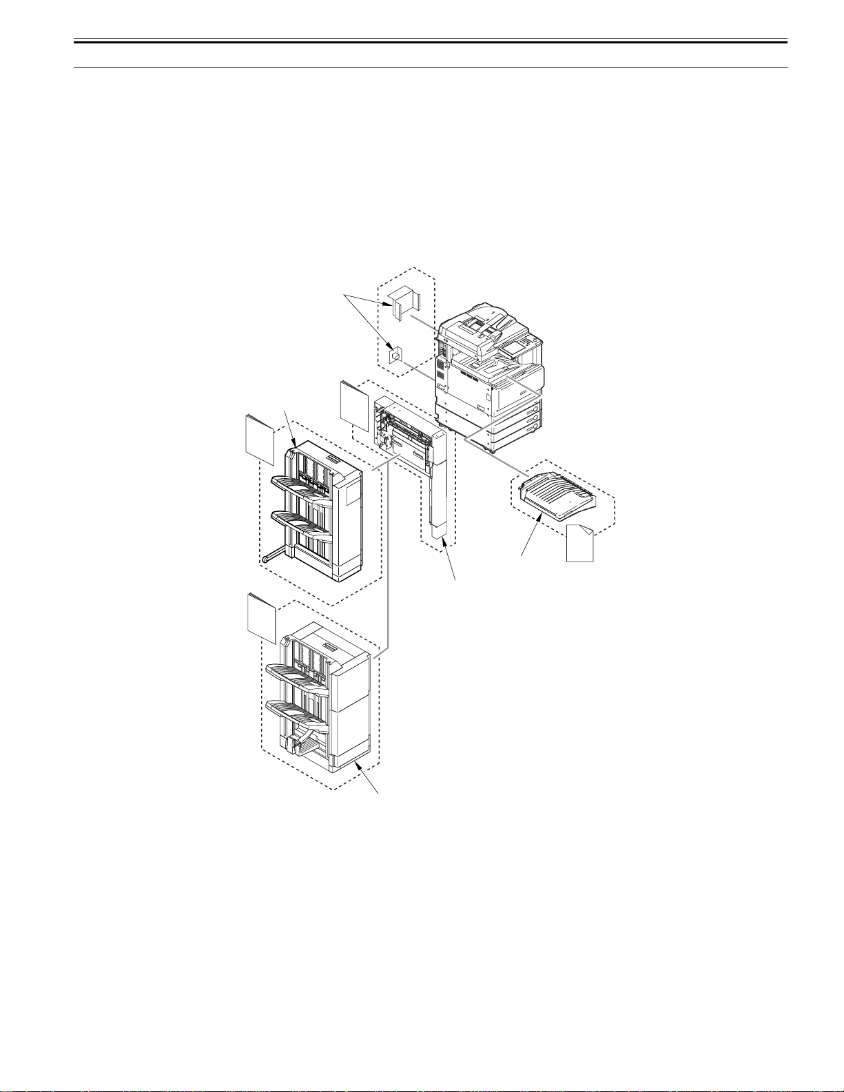
1.1 System Construction
Chapter 1
1.1.1 System Configuration Overview (Delivery Accessories)
Color iR C3380G / Color iR C2880G / Color iR C3380i / Color iR C3380 / Color iR C2880i / Color iR C2880
The delivery accessories for the machine can be divided into three patterns in accordance with the available functions.
- In case a large amount of delivery processing or a several types of delivery processing (e.g., staple, punch) are necessary: system configuration 1 for the delivery
accessories.
- In case some delivery processing (e.g., staple) is necessary: system configuration 2 for the delivery accessories.
- In case some delivery processing (e.g., three-system sorting) is necessary: system configuration 3 for the delivery accessories.
0013-5514
The configuration is shown in the next section.
1.1.2 System Configuration 1 (Delivery Accessories)
Color iR C3380G / Color iR C2880G / Color iR C3380i / Color iR C3380 / Color iR C2880i / Color iR C2880
0013-8249
The system configuration is shown below.
[5]
[1]
[3a]
[1a]
[4a]
[4]
[3]
[2a]
[2]
[1] Finisher-Y1 [1a] Installation Procedure
[2] Saddle Finisher-Y2 [2a] Installation Procedure
[3] Puncher Unit-L1/M1/N1/P1 [3a] Installation Procedure
[4] Buffer Path Unit-E2 [4a] Instruction's sheet of corresponding Installation Procedure
[5] Optional Power Supply-R1 [120V/230V as standard
equipments]
(It is needed when mounting [1] to [3].)
F-1-1
- Mounting the Finisher-Y1.
- Mounting the Buffer Path Unit [4].
- Mounting the Finisher-Y2.
- Mounting the Buffer Path Unit [4].
- Mounting the Puncher Unit-L1/M1/N1/P1
For instructions on installation, see the Installation Procedure if the
respective machine.
1-1
 Loading...