

Canon Color Image Reader - L1 Service Manual

654321
Product Outline
Technology
Periodic Servicing
Parts Replacing and Cleaning
Adjustments
Installation
Appendix
REVISION 1
Color Image Reader - L1
Service Manual

b
b
Application
This manual has been issued by Canon Inc. for qualied persons to learn technical theory,
installation, maintenance, and repair of products. This manual covers all localities where the
products are sold. For this reason, there may be informat ion in this manual that does not
apply to your locality.
Corrections
This manual may contain technical inaccuracies or typographical errors due to improvements
or changes in products. When changes occur in applicable products or in the contents of this
manual, Canon will release technical information as the need arises. In the event of major
changes in the contents of this manual over a long or short period, Canon will issue a new
edition of this manual.
The fo ll owi ng pa ragra ph do es not appl y to an y count ries wher e such prov isi on s are
inconsistent with local law.
Trademarks
The product names and company names used in this manual are the registered trademarks
of the individual companies.
Copyright
This manual is copyrighted with all rights reserved. Under the copyright laws, this manual may
not be copied, reproduced or translated into another language, in whole or in part, without the
written consent of Canon Inc.
(C) CANON INC. 2009
Caution
Use of th is ma nu al shou ld be st ri ctly su pe rvised to avoi d disc lo sure of conf id entia l
information.

c
c
Explanation of Symbols
The following symbols are used throughout this Service Manual.
Symbols Explanation Symbols Explanation
Check.
Remove the claw.
Check visually. Insert the claw.
Check the noise. Use the bundled part.
Disconnect the connector.
Push the part.
Connect the connector. Plug the power cable.
Remove the cable/wire
from the cable guide or wire
saddle.
Turn on the power.
Set the cable/wire to the
cable guide or wire saddle.
Remove the screw.
Tighten the screw.
The following rules apply throughout this Service Manual:
1. Each chap ter contains sections explaining the purpose of specific functions and the
relationship between electrical and mechanical systems with reference to the timing of
operation.
In the diagrams,
represents the path of mechanical drive; where a signal name
accompanies the symbol, the arrow indicates the direction of the electric signal.
The expression "turn on the power" means flippin g on the power switch, closi ng the
front door, and closing the delivery unit door, which results in supplying the machine with
power.
2. In the digital circuits, '1' is used to indicate that the voltage level of a given signal is
"High", while '0' is used to i ndicate "Low". (The voltage value, however, differs from
circuit to circuit.) In addition, the asterisk (*) as in "DRMD*" indicates that the DRMD
signal goes on when '0'.
In practically all cases, the internal mechanisms of a microprocessor cannot be checked
in the field. Theref ore, the operations of the microprocessors used in the machin es
are not discussed: they are explained in terms of from sensors to the input of the DC
controller PCB and from the output of the DC controller PCB to the loads.
The desc riptions in this Service Manual are subject to chan ge with out notice for product
improvem ent or other purposes, and majo r changes will be commu nicated in the form of
Service Information bulletins.
All service persons are expected to have a good understanding of the contents of this Service
Manual and all relevant Service Information bulletins and be able to identify and isolate faults
in the machine.

BLANK PAGE

Contents
Color Image Reader - L1
1 Product Outline
Characteristic ------------------------------------------------------------------1-1
High speed 2-side scan-at one time (DADF) ------------------------------- 1-1
High capacity pickup tray (DADF) --------------------------------------------- 1-1
Next generation scanner unit (DADF/Reader)------------------------------ 1-1
Specication --------------------------------------------------------------------1-1
Name of each area -----------------------------------------------------------1-2
External view ------------------------------------------------------------------------ 1-2
Sectional view ---------------------------------------------------------------------- 1-2
Option conguration ---------------------------------------------------------- 1-2
2 Technology
Basic conguration -----------------------------------------------------------2-1
Function conguration ------------------------------------------------------------ 2-1
Parts conguration ----------------------------------------------------------------- 2-1
Overview of power circuit -------------------------------------------------------- 2-2
Reader controller PCB ------------------------------------------------------------ 2-2
Scanner unit ------------------------------------------------------------------------- 2-3
Basic sequence -------------------------------------------------------------------- 2-4
Controls --------------------------------------------------------------------------2-6
Scanner drive control ------------------------------------------------------------- 2-6
Original size detection ------------------------------------------------------------ 2-7
Dust detection control ------------------------------------------------------------2-12
Magnication change ------------------------------------------------------------2-16
Image processing ----------------------------------------------------------------- 2-16
Fan -----------------------------------------------------------------------------------2-18
Power unit --------------------------------------------------------------------------2-18
Service work -----------------------------------------------------------------------2-19
3 Periodic Servicing
Periodic Servicing List -------------------------------------------------------3-1
4 Parts Replacing and Cleaning
Parts List ------------------------------------------------------------------------4-1
External Covers -------------------------------------------------------------------- 4-1
Main unit ----------------------------------------------------------------------------- 4-1
Motor ---------------------------------------------------------------------------------- 4-2
Fan ------------------------------------------------------------------------------------ 4-2
Sensor -------------------------------------------------------------------------------- 4-3
PCB ----------------------------------------------------------------------------------- 4-3
Main unit -------------------------------------------------------------------------4-4
Removing the Scanner unit ----------------------------------------------------- 4-4
Periodical/Consumable parts, Spots to Clean -------------------------4-6
Turndown Mirror/Free Curved Mirror Cleaning ----------------------------- 4-6
5 Adjustments
Overview ------------------------------------------------------------------------5-1
Adjustment Method ----------------------------------------------------------- 5-3
Measurement during Reader Controller PCB Replacement and After
RAM Clear --------------------------------------------------------------------------- 5-3
Processing after Scanner Unit Replacement ------------------------------- 5-5
Processing after Copyboard Glass Replacement ------------------------- 5-7
Color Image Reader - L1

6 Installation
Color Image Reader - L1 ----------------------------------------------------6-1
Point to Note About Installation ------------------------------------------------- 6-1
Checking the contents ------------------------------------------------------------ 6-2
Turning Off the Host Machine --------------------------------------------------- 6-3
Installation procedure ------------------------------------------------------------- 6-4
Connection of the equipment --------------------------------------------------6-11
Install the external cover --------------------------------------------------------6-19
Afxing Labels ---------------------------------------------------------------------6-26
Post-installation check -----------------------------------------------------------6-27
Perform the Auto Gradation Adjustment ------------------------------------6-28
Appendix
Service Tools ---------------------------------------------------------------------- I
List of Oils/Solvents -------------------------------------------------------------------I
General Circuit Diagram ------------------------------------------------------- II
General Circuit Diagram (1/1) ----------------------------------------------------- II

1
H11.0
H11.0
Product Outline
Product Outline
1
1
Product Outline
Characteristic
Specifi cation
Name of each area
Option confi guration
■
■
■
■
H11.0
H11.0
1-1
1-1
1
1
Product Outline
Product Outline
Characteristic
High speed 2-side scan-at one time (DADF)
Maximum 200 ipm (2-side, B/W, 300 dpi).
Color scan is also available, maximum 80 ipm (one side/2-side, 300 dpi).
High capacity pickup tray (DADF)
Maximum document loading is 300 sheets (80 g/m2 or lower).
Next generation scanner unit (DADF/Reader)
Adapting CMOS line sensor, allows low power consumption and high-speed trigger.
Exposure to light by white color LED, enables low power consumption, size reducing, and
color balance improvement.
Color aberration-free.
•
•
•
•
•
•
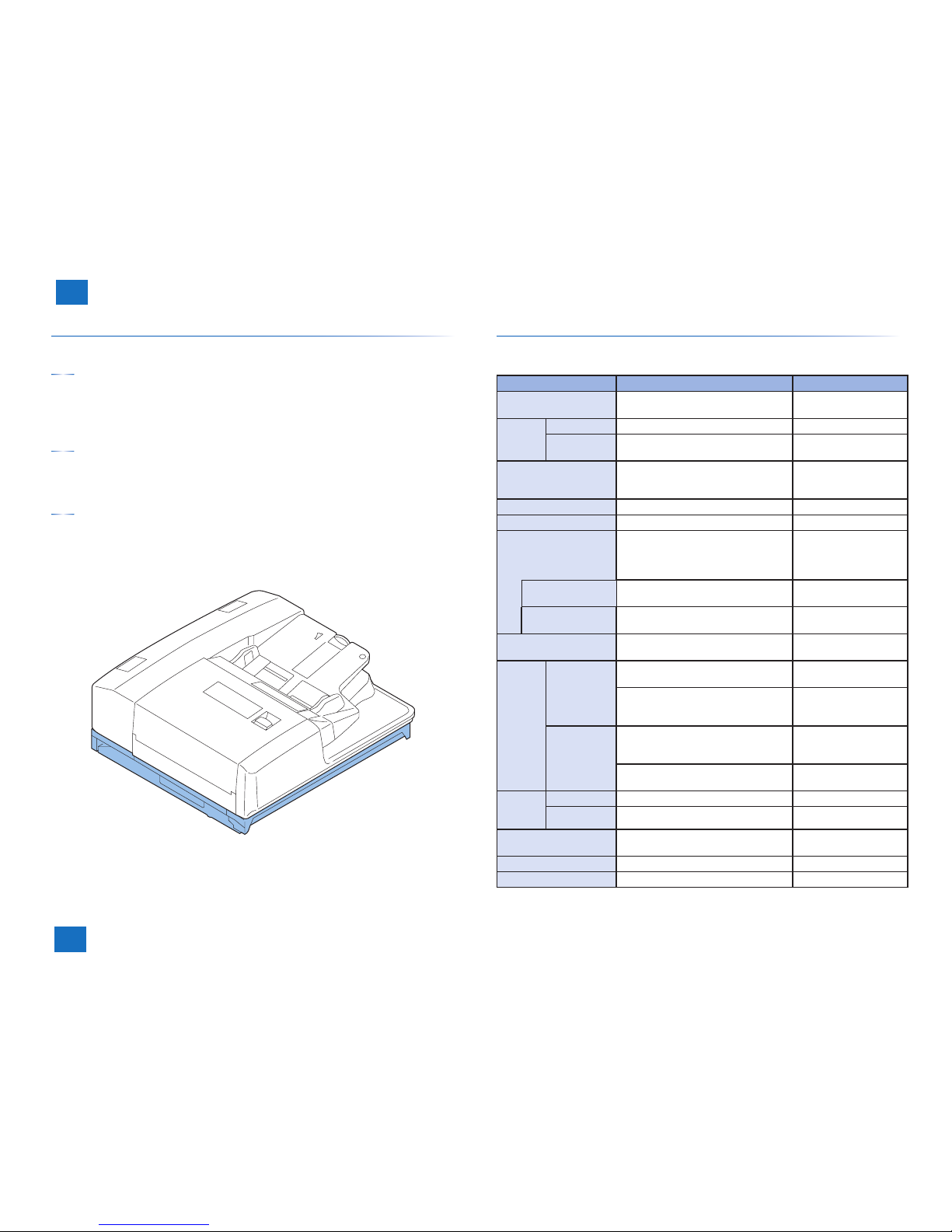
Specifi cation
Following is a specifi cation list of the host machine.
Item Specifi cation/function Remarks
Exposure system High-brightness white LED + refl ection
plate
-
Original
scan
In BOOK mode Scan by movement of scanner unit -
In DADF mode Scan by original stream reading with
scanner unit fi xed
-
Scanning resolution B&W: 600 dpi x 600 dpi
Color: 300 dpi x 300 dpi
600 dpi x 600 dpi *
*: Enabled when the
system upgrade RAM-B1
(optional) is installed
Gradation 256 gradations -
Carriage position detection Scanner unit HP sensor (SR2) -
Magnifi cation change 25% to 400% B&W: scan magnifi cation
change (Sub scanning 2line skipping: 25 to 50%)
Color: degital reproduction
In main scanning
direction
Image processing in main controller PCB -
In sub scanning
direction
Image processing in main controller PCB Some are processed by
the reader controller PCB.
Number of line of CMOS
line censor
4 lines (R, G, B, B/W) -
Original
size detection
In BOOK mode Main scanning direction: detection by
CMOS line censor (scanner unit)
-
Sub scanning direction: detection by refl ection sensor (original size sensor 1 (AB
type) or original si ze sensor2 (Inch type)
-
In DADF mode Main scanning direction: detection by the
original width volume/photointerrupter on
DADF
-
Sub scanning direction: detection by the
photointerrupter on DADF
-
Maximum
original
size
In BOOK mode 297 mm x 431.8 mm -
In DADF mode 304.8 mm x 630 mm -
Dimension 635 x 590 x 72 (W x D x H mm) DADF is not counted for
the height.
Weight Approx. 12 kg -
Option Reader heater For Japan only
Contents of description are subject to change due to product improvement etc.
H11.0
H11.0
1-2
1-2
1
1
Product Outline
Product Outline
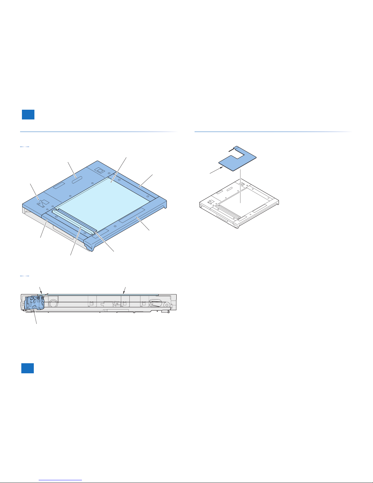
Name of each area
External view
PCB cover
Rear cover
Copyboard glass
Right cover
Front cover
Glass retainer
Stream read glass
Left cover
Sectional view
Stream reading glass
Copyboard glass
Scanner unit
Option confi guration
Followings are the options for the host machine.
Reader heater

BLANK PAGE

2
2
2
Technology
Technology
Technology
Basic confi guration
Controls
■
■
2-1
2-1
2
2
Technology
Technology
Basic confi guration
Function confi guration
Following is the list of functions.
Original size detection
Image processingDust detection
Scanner drive
Reader controller PCB
A/D conversion
Image scanning
Scanner unitReader unit
Magnification change
Main controller PCB
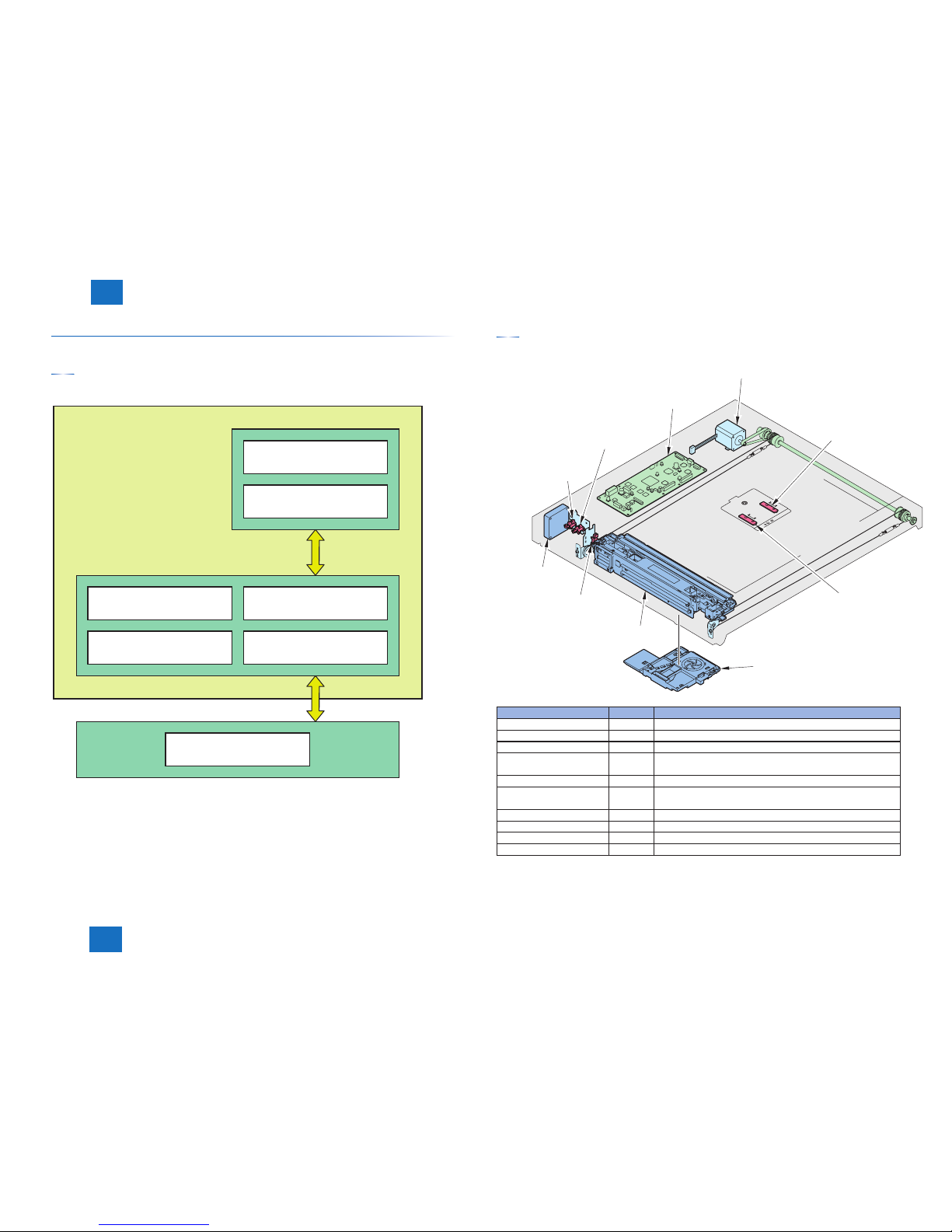
Parts confi guration
Followings are the positions and names of main confi guration parts.
Original size sensor 2
(CF2)
Original size sensor 1
(CF1)
Scanner unit
cooling fan (FM2)
Scanner unit
DADF
open/closed
sensor 1
(SR1)
Scanner unit
home position sensor
(SR2)
Scanner unit
exhaust fan (FM1)
Reader controller PCB
(PCB1)
Scanner motor (M1)
DADF
open/closed
sensor 2
(SR3)
Component part Symbol Function/specifi cation
Scanner motor M1 2 phase pulse motor: pulse control
Scanner unit exhaust fan FM1 Exhaustion of scanner unit
Scanner unit cooling fan FM2 Cooling of scanner unit
DADF open/closed
sensor 1
SR1 DADF open detection (DADF is detected at 5 degree)
Scanner unit HP sensor SR2 Scanner unit HP detection
DADF open/closed
sensor 2
SR3 DADF open detection (size detection timing is detected
when DADF is open at 25 degree.
Original size sensor 1 CF1 Size detection in sub scanning direction (AB type)
Original size sensor 2 CF2 Size detection in sub scanning direction (INCH type)
Scanner unit --- Image reading, analog image processing
Reader controller PCB PCB1 Control of entire reader, digital image processing
2-2
2-2
2
2
Technology
Technology
Overview of power circuit
Control of the host machine is conducted at the reader controller PCB.
Reader controller PCB also controls the DADF driver PCB and DADF scanner unit.
Following is the relations of each electrical part.
Sensor
Fan
Motor
Host
machine
Reader
controller
PCB
Scanner unit (reader)
Scanner unit (DADF)
DADF driver PCB
Error Code
E270 (Error in the main scanning/sub scanning synchronization signal).
-0001 Sub scanning synchronization signal (VSYNC) is not properly transmitted from CMOS
PCB (front side scanner unit), and this causes image failure or abnormal termination.
-0002 Sub scanning synchronization signal (VSYNC) is not transmitted due to the error in the
main scanning synchronization signal (HSYNC), and this causes image failure or abnormal
termination.
-0101 Sub scanning synchronization signal (VSYNC) is not properly transmitted from CMOS
PCB (back side scanner unit), and this causes image failure or abnormal termination.
E280 (Communication error between reader controller PCB – scanner unit)
- 0001 If the communication is not started within the specifi ed time between reader controller
PCB – front side scanner unit.
- 0101 If the communication is not started within the specifi ed time between reader controller
PCB – back side scanner unit.
E400 (Communication error between reader controller PCB – DADF)
-0001 If reception error occurs during communication between reader controller PCB - DADF
-0002 If reception error occurs during communication between reader controller PCB - DADF
E490 (Error caused by incorrect DADF type)
-0001 If a not-supported DADF type is installed.
E473 (DDI communication error)
-0000 If the reader controller PCB detects communication error between the main controller
PCB and the reader controller PCB.
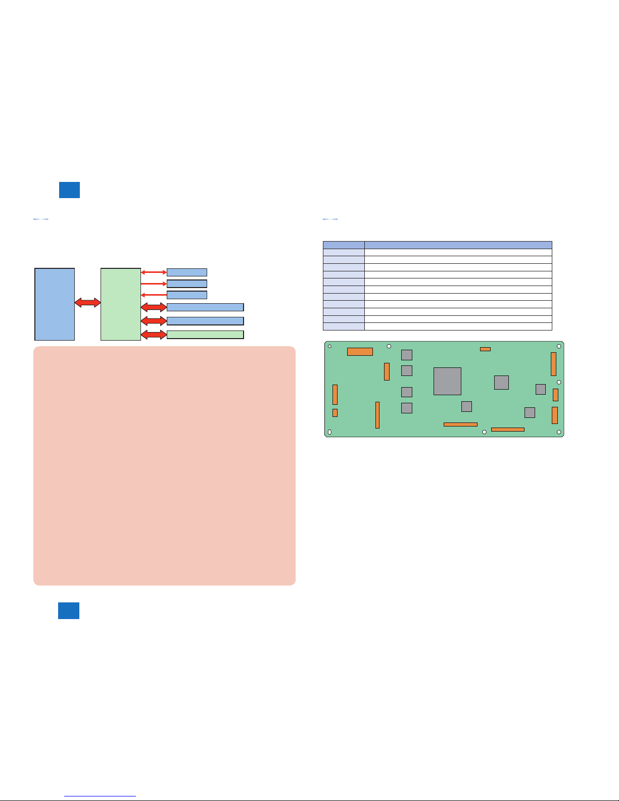
Reader controller PCB
Following is the function confi guration of reader controller PCB.
Jack No Role
J101 Power supply from the host machine (printer unit)
J103 Connection with DADF open sensor 1/2, scanner unit HP sensor
J104 Connection with fan
J201 Connection with scanner unit on reader
J202 Connection with scanner unit on DADF
J203 Communication with DADF
J204 Connection with PC
J205 Control of scanner motor
J206 Communication with main controller
J207 Connection with original size sensor 1/2
J208 Power supply for DADF
,
,
,
,
,
,
,
+%
,
,
,
,
2-3
2-3
2
2
Technology
Technology
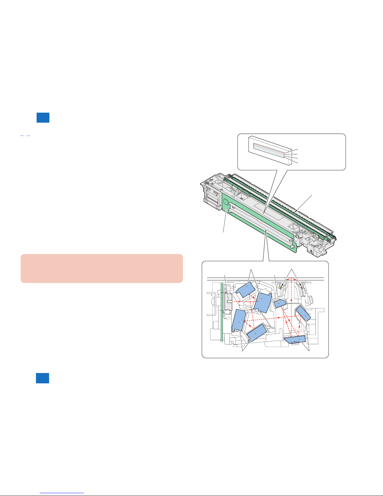
Scanner unit
Original exposure and scanning are performed by the integrated scanner unit of LED, mirror,
lens and CMOS line sensor.
Light emitted from LED is refl ected by the original and reaches the CMOS line sensor through
the 3 folding mirrors and 4 free curvature mirrors.
1. LED lamp unit
On LED lamp unit, the light is generated from the 2 LED lamp PCBs (LED chip: 48 pieces per
PCB).
Generated light is exposed to the original through the refl ection plate.
2. Free curvature mirror
Scanner unit is equipped with the 3 folding mirrors and 4 free curvature mirrors.
Free curvature mirror has symmetric facet in main scanning direction and asymmetric facet in
sub scanning direction against the optical axis.
3. CMOS line sensor
CMOS line sensor scans the image per 1image line.
CMOS line sensor has 4 lines (R, G, B, BW). At B&W scanning, it uses 1 line (B/W) and uses
3 lines (R, G, B) at color scanning.
Error code
E301 (insuffi cient light intensity)
-0001 The light intensity during front side shading is lower than the standard level
-0101 The light intensity during back side shading is lower than the standard level
Free curved mirrors Turndown mirrors
CMOS line sensor
Free curved mirrors
Turndown mirrors
LED (light source)
CMOS PCB
LED lamp unit
CMOS line sensor
Red (R) line
Greeen (G) line
Blue (B) line
Black & white (B / W) line
2-4
2-4
2
2
Technology
Technology
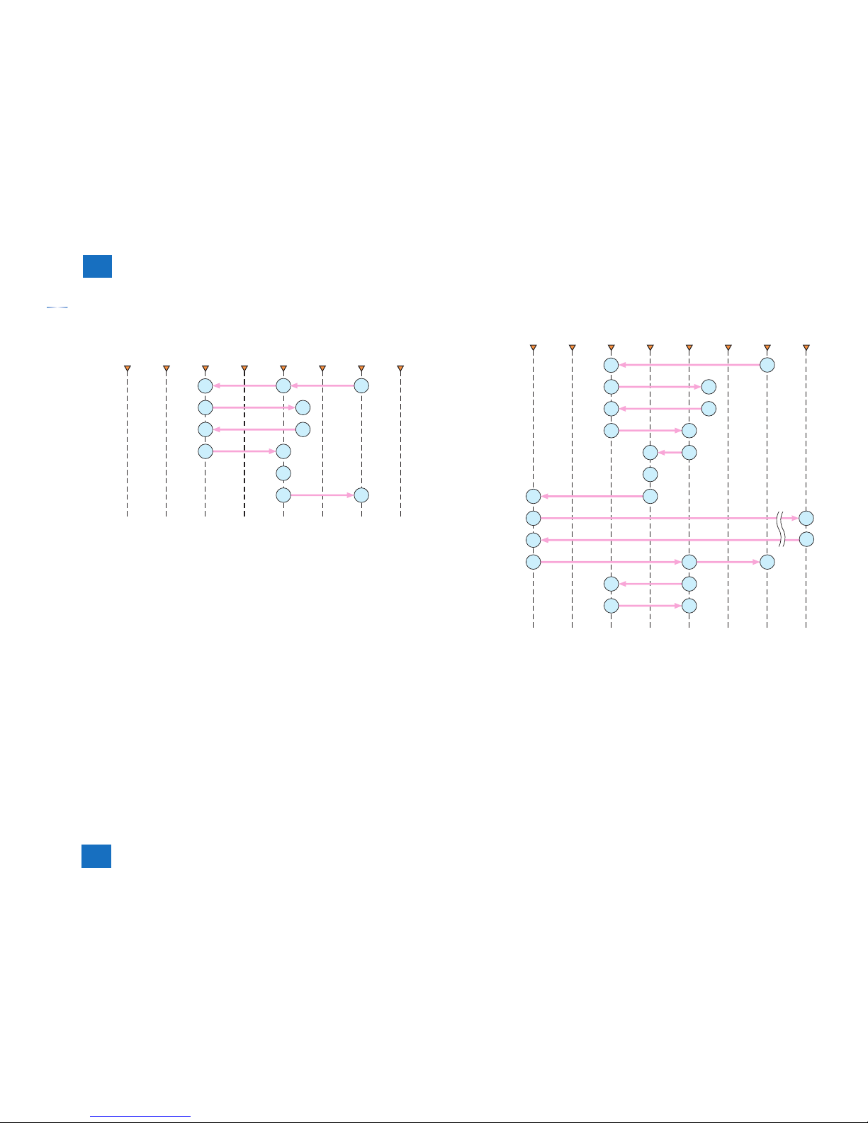
Basic sequence
At power ON
1. HP positioning
2. move to shift
shading start position
3. CMOS-LIVE control *2
gain correction
4. Completion operation
*1: Shifts only if the DADF is open.
*2: Controls by turning on/off the power of the scanner unit and the circuitry
around it for power saving and for protection against overheating.
*3: Shifts only if the DADF is open.
*1
*3
Stop
position
Start
position
Stream
reading
position
Shading
position
Home
position
Shading
start
position
Image
leading
edge
Original
size
detection
position
■
At start key ON (Book mode/1 sheet original)
1. HP positioning
2. move to shift
shading start position
7. Completion operation
6. Original scan
3. move to shift shading
4. fixed shading
- white plate dust detection
- shading correction
5. Start position
move to shift
*1: Executed only if 1 min or more (power off) has passed from the previous session.
*2: Shifts only if the DADF is open.
*3: Shifts only if the DADF is close.
*1
*1
*2
*3
*3
Stop
position
Start
position
Stream
reading
position
Shading
position
Home
position
Shading
start
position
Image
leading
edge
Original
size
detection
position
■

2-5
2-5
2
2
Technology
Technology
At start key ON (DADF mode/1 sheet original)
1. HP positioning
2. move to shift
shading start position
7. Completion operation
6. original stream
reading scan
6. shifts to point of
the stream reading
glass dust detection
3. move to shift shading
4. fixed shading
- white plate dust detection
- shading correction
5. Steam reading position
move to shift
*1: Executed only if 1 min or more (power off) has passed from the previous session.
*2: [Reference] Technology > Controls > Dust detection > Stream reading glass dust detection control
*3: Shifts only if the DADF is open.
*4: Shifts only if the DADF is close.
*1
*1
*3
*2
*4
*4
Stop
position
Stream
reading
position
Shading
position
Home
position
Shading
start
position
Image
leading
edge
Original
size
detection
position
■
2-6
2-6
2
2
Technology
Technology
Controls
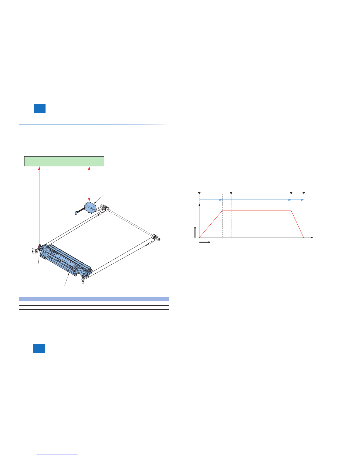
Scanner drive control
Confi guration of drive system
Following is the parts confi guration related with scanner drive system.
ACOM, BCOM
HP
Reader controller PCB
Scanner motor (M1)
Scanner unit
Scanner home position
sensor (SR2)
Component parts Symbol Function
Scanner motor M1 Control of the drive/stop, direction and speed of motor rotation
Scanner unit HP sensor SR2 Scanner unit HP detection
Scanner unit - Image reading, analog image processing
■
Scanner motor control
Following is the control system confi guration related with the scanner motor control.
Motor driver on the reader controller PCB controls the drive/stop, direction and speed of
scanner motor rotation in accordance with the signals from CPU.
1) Backward operation after image scanning
Backward operation after image scanning until shading position of scanner unit is control-
led by 468 mm/sec regardless of color mode.
2) Forward operation at image scanning
At image scanning, the following motor control controls the scanner unit operation.
Start position
Acceleration
Image leading edge
Normal speed
Image trailing edge
Deceleration
Stop
Shift
speed
Shift length
[1] [2] [3] [4]
[1] Acceleration Zone: accelerates to suit the selected mode.
[2] Approac h Zone : moves for speed stabilization.
[3] Image Read Zone: reads the image at a specific speed.
(if black-and-white/SEND mode, twice as fast as in full-color mode.)
[4] Deceleration Zone: past the image trailing edge, immediately decelerates and stops.
■

2-7
2-7
2
2
Technology
Technology
Following shows the scanning speed in each mode.
Function Mode Scan speed
Copy / SEND
B&W 468 mm/sec
Full color 203 mm/sec
Error Code
E202 (error in the scanner home position)
-0001 Error during home position detection operation (outward) of the front scanner unit.
-0002 Error during home position detection operation (homeward) of the front scanner unit.
Service Mode
(Lv.1) COPIER > ADJUST > ADJ-XY> ADJ-X
(Scanner system image leading edge position adjustment)
Enter the value to adjust the position of image leading edge.
Setting range: 1 – 100 (changing the value by 10 moves the position by 1mm)
Original size detection
Original size is identifi ed based on the result combinations of refl ection light at the specifi c
point on the refl ection sensor and the scanner unit. To prevent the original from moving when
closing the DADF, there is 2 point original size detection per each size on the scanner unit.
In main scanning direction: scanner unit (AB type: 9 point measurement, Inch type: 6 point
measurement)
In sub scanning direction: refl ection type photo sensor (AB type: 1 point, Inch type: 1 point)
Original size is detected in the following procedure.
1) External light search (in main scanning direction only)
While keeping the LED lamp unit OFF, the CMOS sensor level of each detection point is
measured in main scanning direction.
2) Output level detection of each sensor
While keeping the LED lamp unit ON, CMOS sensor level of each detection point is
measured in main scanning direction.
The machine turns ON the LED of refl ection type photo sensor in sub scanning direction and
measures the sensor output.
Original size is identifi ed by these output combination.
•
•
2-8
2-8
2
2
Technology
Technology
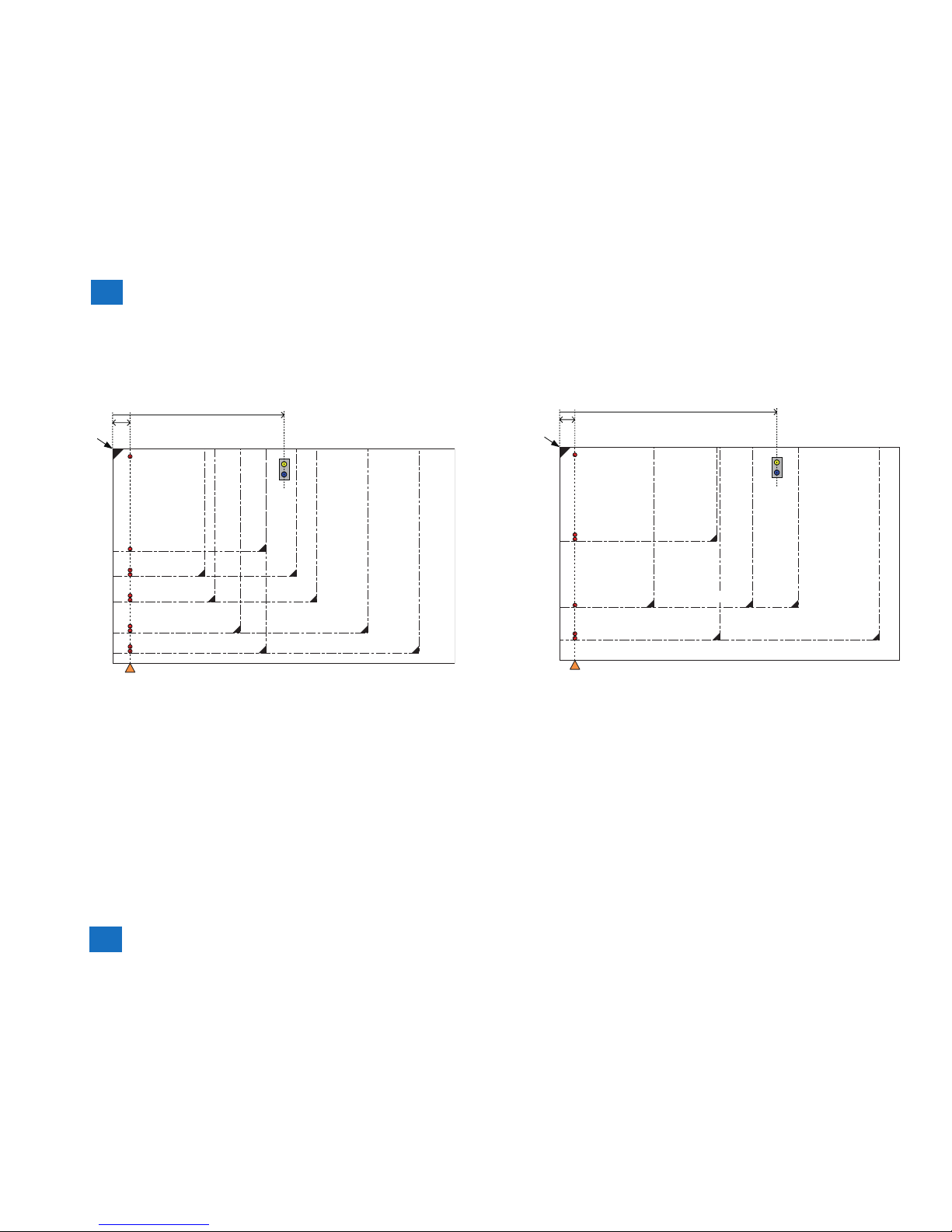
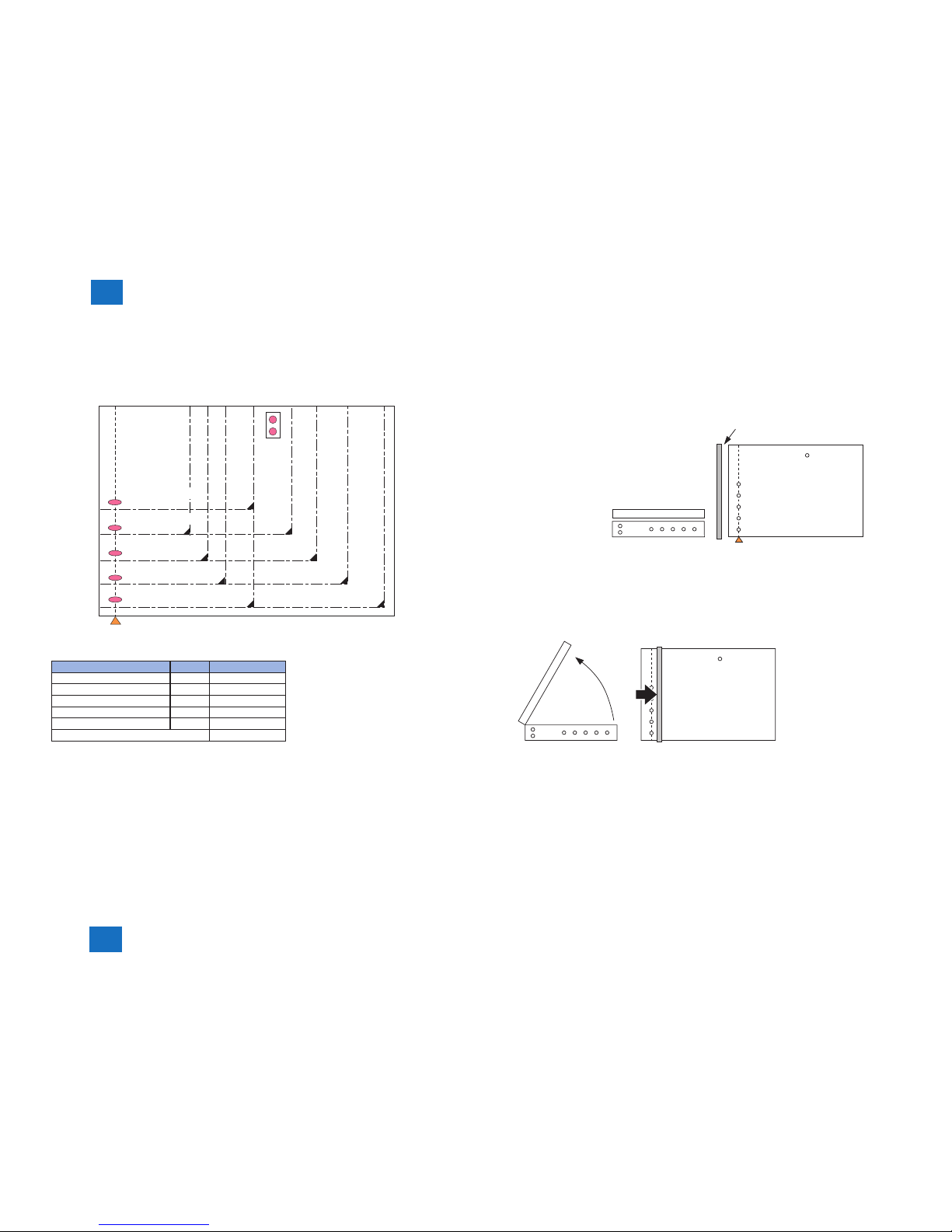
Original size detection position
In main scanning direction, the machine moves the scanner unit to the following position in
reference to the original position and measures the CMOS level of each detection position. In
sub scanning direction, original size is identifi ed by the following sensors.
A5
A5-R
A4-R
A4
A3
B4
B5
B5-R
20 mm
30.0 mm
146.0 mm
169.0 mm
178.0 mm
197.0 mm
206.0 mm
Original
size sensor 1 (CF1)
B6
0 mm239.5 mm
244.0 mm
253.0 mm
284.0 mm
293.0 mm
Original
push-on position
Scanner unit
original detection position
■
STMT-R
LETTER_R
LEGAL
LETTER
LEDGER
Original
push-on position
20 mm
30.0 mm
126.7 mm
135.7 mm
211.9 mm
STMT
0 mm 311 mm
264.0 mm
267.0 mm
Original
size sensor 2 (CF2)
Scanner unit
original detection position

2-9
2-9
2
2
Technology
Technology
Following is the combination of detection result and original size.
A/B: Original presence/absence detection result of 2 points (Refer to [2 point original detec-
tion at each detection position].).
Y: Output level has no change (refer to [Detection operation]).
-: Output level has change (refer to [Detection operation]).
Original size
Scanner unit detection position
Original size sensor 112345
ABABABABAB
A3 YYYYYYYYYY Y
B4 YYYYYYYY - - Y
A4R YYYYYY - - - - Y
A4 YYYYYYYYYY B5 YYYYYYYY - - B5R YYYY - - - - - - Y
A5 YYYYYY - - - - B6 YYYY - - - - - - A5R YY-------- None - - - - - - - - - - -
Original size
Scanner unit detection position
Original size sensor 2123
ABABAB
11” x 17” YYYYYY Y
LGL Y Y Y Y - - Y
LTRR Y Y Y Y - - LTR YYYYYY STMTR Y Y ---- STMT Y Y Y Y - - Absent - - ---- -
To keep the high accuracy detection even though an original moves when the DADF is
closed, this machine has 2 types of controls.
a. 2 point original detection at each detection position
In main scanning direction, the machine determines whether the original is present or not
from the 2 points of CMOS output near the original detection position.
Near 4 mm
Near 13 mm
1A: additional point
of detection
Original size
border line
Original size
border line
1B: conventional point
if detection
Result
Judgment
AB
Y Y Present
Y - Present
- Y Present
- - Absent
* Signal change with DADF Open to Close
Changed: -
Others: Y
The machine uses OR combinations of 2 points for identifi cation.
2-10
2-10
2
2
Technology
Technology
b. Priority on the front original presence
As a result of main scanning direction measurement, if the original absence is detected at
the rear while the original presence is detected at the front, a priority is given to the result of
original presence at the front.
Point of detection 1
Point of detection 2
Point of detection 4
Point of detection 3
Point of detection 5
Scanner unit
original detection position
B5
Original
size
sensor1
Original detection position Result Identifi ed size
1YY
2-Y
3-Y
4YY
5--
Judgment B5
* Signal change with DADF Open to Close
Change: -
Others: Y
Detection operation
Following is the overview of operation for original size detection (AB type).
1) Wait status
Scanner unit: shading position
LED lamp unit: OFF
Original size sensor: OFF
Original detection position
Scanner unit
Original size
sensor 1
Reader unit
DADF
Copyboard
glass
Point of detection 1
Point of detection 2
Point of detection 3
Point of detection 4
Point of detection 5
DADF open/closed sensor 2
DADF open/closed sensor 1
2) DADF opened (The angle of DADF is 25 degree or more).
Scanner unit: It moves to the original detection position (20mm from the original push-on
position)
LED lamp unit: OFF
Original size sensor: OFF
■

2-11
2-11
2
2
Technology
Technology
3) Close DADF (The angle of DADF is from 5 to 25 degree).
3-1) The external light detection operation is performed. Since the area covered by an
original will be blocked from external light, the machine will assume the absence of an
original at points that detect external light. After the DADF sensor 2 detects [Close],
the external light detection operation is started.
In case of the described original size, A3/B4/A4/B5 are excluded from the list of pos-
sible sizes at this point.
original
: external light
25 degrees
3-2) After the external light detection operation, the machine turns ON the LED in the
main scanning direction and the refl ected light is detected by the CMOS line sensor
(5 points). After the fi rst detection, it continues detection by the specifi ed interval (it
completes after 3 sec). The original size sensor 1 starts detection in the sub scanning
direction.
25 degrees
: LED light
4) DADF fully closed (the angle of DADF is 5 degree or less).
The machine monitors the changes of output level of each sensor for 3 sec from when the
DADF open sensor 1 detects the [Close] status. The machine determines the original pres-
ence in the point where the output level has no change.
The machine identifi es the original size from the combination of the level change at 5
points (priority on the front original presence).
5 degrees
5) Wait status (wait for start key)
Scanner unit: shading position
LED lamp unit: OFF
Original size sensor: OFF
2-12
2-12
2
2
Technology
Technology
Dust detection control
Overview
The timing of dust detection is as follows.
[2][1] [2] [2]
[3]
[3]
Start key
ON
Before stream
reading
1st sheet
scanned
2nd sheet
scanned
Between
sheets
After scan Standby
[1] White plate dust detection control
[2] Steam reading glass / Scanning glass dust detection control,
Dust detection correction control (continuous lines)
[3] Dust detection correction control (noncontinuous lines)
Scanner unit
(DADF)
- White plate dust detection
- Stream reading glass dust detection
- Dust detection correction (continuous lines)
- Dust detection correction (noncontinuous lines)
Scanner unit
(Reader)
- White plate dust detection
- Scanning glass dust detection
- Dust detection correction (continuous lines)
- Dust detection correction (noncontinuous lines)
■
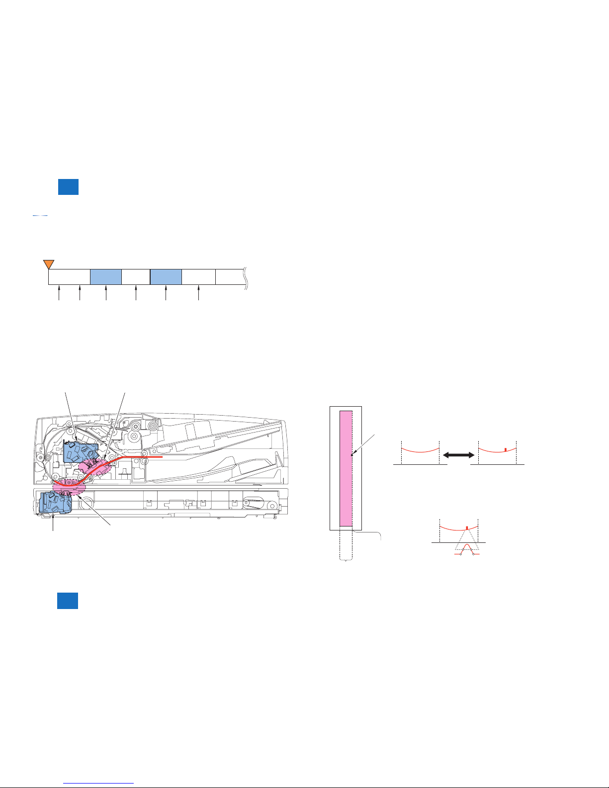
White plate dust detection control
In this machine, the fans cool down the inside of the DADF to prevent the overheating at
stream reading operation. As a result, dust in the DADF may stick to the white plate and it
may cause the lines on the image.
To reduce the infl uence from the dust, the white plate dust detection and correction are per-
formed.
(1) White plate dust detection
The machine compares the shading coeffi cient obtained from shift shading and the shading
coeffi cient obtained from fi xed shading to identify the presence/absence of dust and, if any,
identifi es the coordinates and width of the area.
(2) White plate dust correction
If the machine detects the dust as a result of white plate dust detection, it interpolates the
shading coeffi cient of the area using the shading coeffi cient of both sides so as to decrease
the effects of the presence of dust. It executes the shading correction using the shading coef-
fi cient obtained after the interpolation.
When the dust is detected as a result of white plate dust detection, the machine interpolates
the shading coeffi cient of the dust area using the shading coeffi cient of both sides so as to
reduce the effects of the dust. The shading correction is executed after the interpolation.
[Detection Algorithm]
[Correction Algorithm]
Computation of shading
coefficient
(shift shading to
reference area)
Computation of shading
coefficient
(from fixed shading to
shading correction position)
Detection of coordinates of
start of dust and width
Correction of dust area
coefficient using data of both sides
Fixing shading position
Shading correction position
Reference area
(Shading coefficient
White plate
Area
of dust
Comparison
■
2-13
2-13
2
2
Technology
Technology
Stream reading glass dust detection control
The machine checks the presence/absent of dust on the stream reading glass and the DADF
platen roller 1. It then changes the point of reading or executes image correction (refer to
[dust detection correction control (continuous lines)]) depending on the result of detection to
avoid the reproduction of dust particles in its output images.
a. At the start of a job
The scanner unit moves to the reading position saved at the detection of the previous job
ends.
After it moves, the dust detection is executed. If the dust is detected, the machine executes
dust correction by making correction on the pixels on both sides of the area where dust is
found.
[1] It moves to the reading position.
b. Between sheets
The dust detection is executed. If the dust is detected, the machine executes dust correction
by making correction on the pixels on both sides of the area where dust is found.
The scanner unit does not move due to the dust detection.
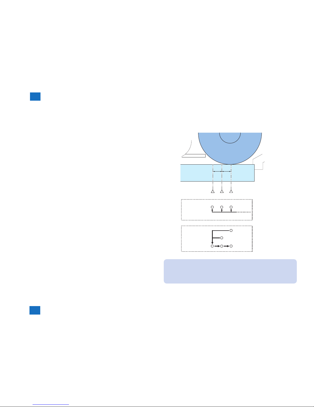
c. At the end of a job
1) The scanner unit moves to the default reading position A.
[2] It moves to the reading position A.
*1: In case that the reading position at the start of a job is one other than A.
2) The dust detection is executed. If there is no dust on the A position, the machine saves
the A as a reading position for a next job and fi nishes the dust detection.
3) If there is a dust on the A position, the machine execute the dust detection on the B
position. If there is no dust on the B position, the machine saves the B as a reading
position for a next job and fi nishes the dust detection.
[3] It moves to the B position.
4) If there is a dust on the B position, the machine executes the dust detection on the C
position. If there also is a dust on the C position, the machine saves the position where
the least dust is found among the A, B or C positions as a reading position for a next job
and then, displays an alarm to perform the cleaning.
[4] It moves to the reading position C.
■
A
0.5 mm 0.5 mm
B
C
*1
*1
At the start
of a job
[1]
At the end
of a job
[3] [4]
[2]
MEMO:
(Lv.1) COPIER > OPTION > IMG-RDR > DFDST-L1
Adjustment of the dust detection level between sheets
(Lv.1) COPIER > OPTION > IMG-RDR > DFDST-L2
Adjustment of the dust detection level at job end
 Loading...