

Canon Color Bubble Jet BJC-4400 Series, Color Bubble Jet BJC-4300, Color Bubble Jet BJC-4400 Service Reference Manual
™
C olor Bubb le Jet
Printer
BJC-4400
Series

QY8-13P1-000
MAY. 1998
COPYRIGHT 1998 CANON INC. CANON BJC-4400 PRINTED IN JAPAN (IMPRIME AU JAPON)
REVISION 0
SERVICE
REFERENCE MANUAL
Q30-2830-220 120V(CCSI)
Q30-2830-221 120V(CAN)
Q30-2830-222 (UNIVERSAL)
Q30-2830-230,630 220V-240V(EUR)
Q30-2830-231,631 220V-240V(GER)
Q30-2830-232,632 220V-240V(FRN)
Q30-2830-280,680 220V-240V(UK)

Application
This manual has been issued by Canon Inc. for qualified persons to learn technical theory, installation, maintenance, and repair
of products. This manual covers all localities where the products are sold. For this reason, there may be information in this
manual that does not apply to your locality.
Corrections
This manual could include technical inaccuracies or typographical errors due to improvements or changes in the products. When
changes occur in applicable products or in the content of this manual, Canon will release technical information as the need arises.
In the event of major changes in the contents of this manual over a long or short period, Canon will issue a new editions of this
manual.
The following paragraph does not apply to any countries where such pr ovisions ar e inconsistent with local law.
T rademarks
The product names and company names described in this manual are the registered trademarks of the individual companies.
Copyright
This manual is copyrighted with all rights reserved. Under the copyright laws, this manual may not be copied, reproduced or
translated into another language, in whole or in part, without the written consent of Canon Inc., except in the case of internal
business use.
Copyright 1998 by Canon Inc.
CANON INC.
BJ Products Technical Support Dept
16-1, Shimonoge 3-chome, Takatsu-ku, Kawasaki-shi, Kanagawa 213, Japan
This manual was produced on an Apple MacintoshPower Mac 8500/180 personal computer and Apple
LaserWriter16/600PS-J laser beam printer; final pages were printed on Varityper 5300 with 4000-J RIP. All graphics were
produced with MACROMEDIA FREEHAND 5.5J.
All documents and all page layouts were created with QuarkXPress 3.3J.

I.PREFACE
CHAPTER 1: MAJOR CHANGES
This chapter explains the main differences between BJC-4300 and BJC-4400.
CHAPTER 2: SERVICE MANUAL
This chapter explains the main differences between the SERVICE MANUAL of the BJC-4300 and
BJC-4400.
NOTE
· Page No. displayed are those of pages to be replaced for each item.
This manual is based on the following manuals, and only includes differences between BJC-4300 and
BJC-4400.
QY8-1352-000 BJC-4300 SERVICE MANUAL, Rev.0
II.CONTENTS

CHAPTER 1
MAJOR CHANGES

I.MAJOR CHANGES
BJC-4400 contains the following modifications compared to BJC-4300.
1.1 PRODUCT SPECIFICATIONS
1. Faster throughput speed(especially in HS mode)
2. T-shirt Transfer (TR-201) added as media type
1.2 PRINTER MECHANICAL SYSTEM
1. Countermeasures for quality improvements to the current model were incorporated
Shape changes : Carriage, paper delivery guide, platen and bottom case
Additional changes : Increased area and amount of grease application
1.3 PRINTER ELECTRICAL SYSTEM
1. To improve throughput speed, the carriage motor, the paper feed motor and the motor driver were
modified.

CHAPTER 2
SERVICE MANUAL
Part 2: Product Specifications
BJC-4400
2-1
1. PRODUCT OUTLINE
1.1 Product Outline
This full color bubble jet desktop printer not only realizes high image printing through the implementation
of the PhotoRealism concept, but also higher speed printing compared to previous models.
This printer achieves high image printing by adopting "drop modulation technology" in the color BJ
cartridge and the photo BJ cartridge.
The expanded printing environment has allowed the printer to have banner printing capabilities. The
printer can also be used as a compact color scanner when the scanner cartridge is installed in the carriage.
All the function settings are easily set by the personal computer. The operation is easily performed with the
bidirectional Centronics interface (effective only for the device ID response)
This printer uses a built-in AC adapter. This is a small and light weight personal color printer with high
performance capabilities.
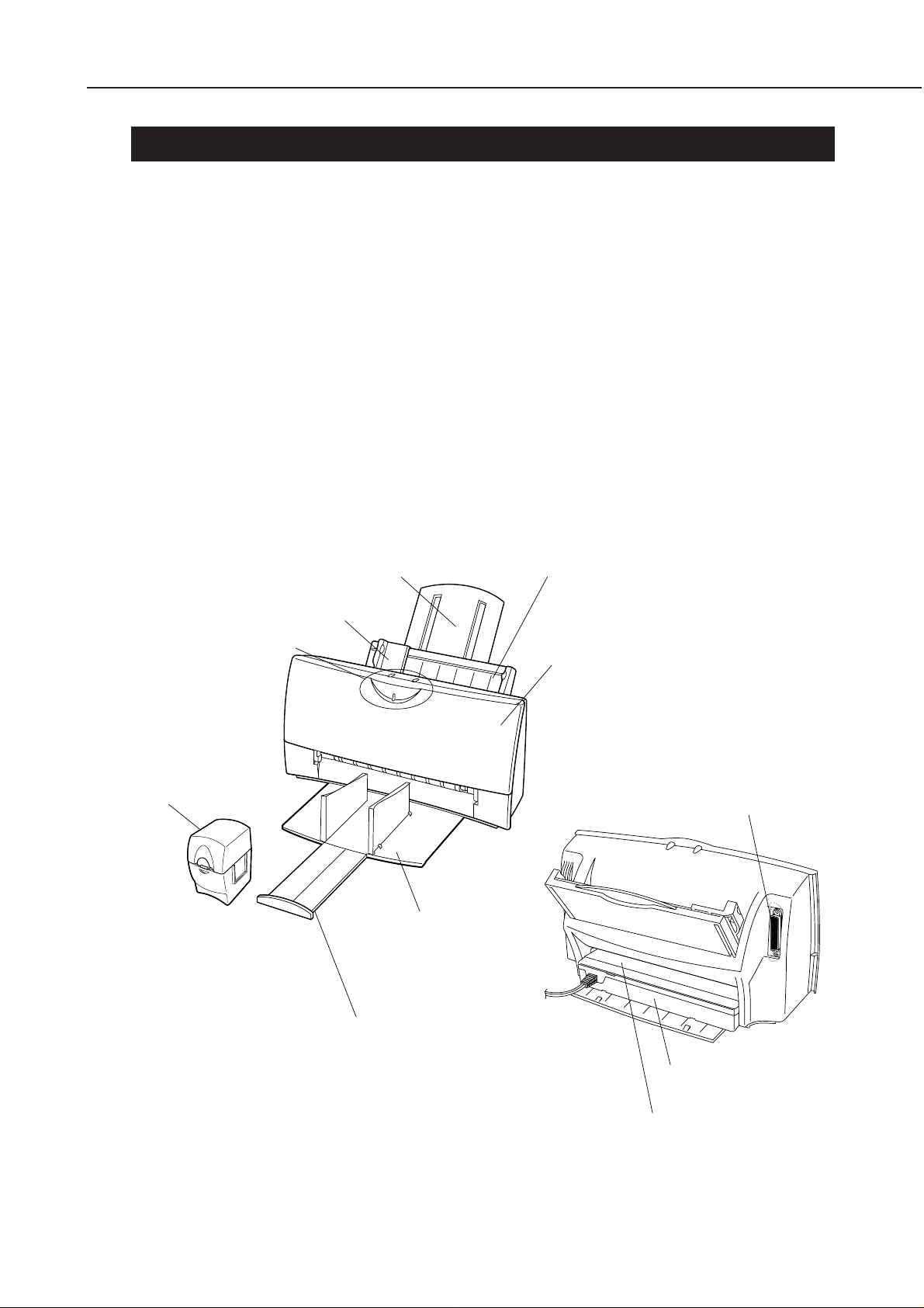
Figure 2-1 Printer Exterior
Paper Guide
Operator Panel
BJ Cartridge Container
Paper Support
Cut Sheet Feeder
Front Cover
Parallel Interface Connector
Paper Output Tray
Paper Output Tray Extension Guide
AC Adapter
Manual Feeding Slot

Part 2: Product Specifications
x 231.6 mm D x 203 mm H
Weight: Approx. 3.5 kg (7.7 lbs) (including color BJ cartridge)
3. Built-in AC adapter employs a high-current capable switching power supply.
4. Automatic power control (auto power on/off)
5. High quality printing of 720 x 360 dpi (in both monochrome and black when using the special printer
driver)
6. Two standard built-in printer control modes
LQ mode (EPSON LQ-2550 emulation)
BJ mode (IBM Proprinter X24E emulation)
[Canon extended mode is supported when using the canon printer driver.]
7. User replaceable BJ cartridge and adopting drop modulation technology color/ photo BJ cartridge .
Color BJ Cartridge Drop modulation technology has been adopted.
(Multi drop) It has separate ink cartridges (Bk) (Y, M, C) and the head with 136 nozzles
in a vertical line; 64 nozzles (Bk) + 24 nozzles x 3 (Y, M, C).
Black BJ Cartridge Contains the black ink and the head with 128 nozzles.
Depending on each sales territory, it is not packed with the printer, but is
available separately.
Photo BJ Cartridge Drop modulation technology has been adopted.
(Multi drop) It has integrated ink cartridges with the head with 136 nozzles in a vertical
line; 64 nozzles (Bk) + 24 nozzles x 3 (Y, M, C).
Black ink cartridge Black ink cartridge for the color BJ cartridge.
Color ink cartridge Tri-color (Y, M, C) ink cartridge for the color BJ cartridge.
(*Previous color and photo BJ cartridges that do not use drop modulation technology may be used,
however the printing quality will be the same as when drop modulation technology is not used.)
8. Device ID compatible to "Plug and Play"
(Responds only to the device ID/status of nibble mode)
9. Banner printing capabilities.
10. Capable of the double paper feeding with the leverless cut sheet feeder and manual feed. (It is possible
to feed paper manually even when the paper has been set on the cut sheet feeder.)
11. Photo quality printing using the Photo kit option and the photo printing special driver.
12. Cartridge container packed with the printer.
13. High quality photo image input using the option color image scanner cartridge.
BJC-4400
1.2 Features
1. Higher speed printing
Black BJ Cartridge : 5.5 PPM (HS mode)
Color BJ Cartridge : 2.2 PPM (HS mode)
2. Compact (desk-top size)
Dimensions: 383 mm W
2-2

Part 2: Product Specifications
2. SPECIFICATIONS
2.1 Printer Specifications
1. Type
Desk-top serial color bubble jet printer
2. Paper feeding method
Auto feeding and manual feeding
3. Cut Sheet Feeder capacity
Plain paper: Maximum 10 mm (approximately 100 pages of 64g/m2paper)
Envelopes: 10 envelopes (Commercial number 10 and DL)
Transparencies: 50 sheets
BPF: 10 sheets
Glossy film/ BJ cloth: One page with the manual feeding
Scanning document: Place between the scanning holder. One page with the ASF.
4. Manual feeding slot capacity
One sheet
BJC-4400
5. Paper weight
Automatic feed / Manual feeding slot: 64 to 105 g/m2(17 lbs to 28 lbs)
6. Printing speed
Burst
Color BJ Cartridge (Black printing) Black BJ Cartridge (Black printing)
HQ mode 173 cps (10 cpi) 346 cps (10 cpi)
HS mode 271 cps (10 cpi) 542 cps (10 cpi)
7. Printing direction
Unidirectional
(Print direction is automatically changed according to optimum printing directional control.)
8. Printing width
Maximum 8”
9. Line feed speed
90 ms/line (128/360” line)
10. Built-in printing control modes
LQ mode: Epson LQ-2550 emulation
BJ mode: IBM Proprinter X24E emulation
(Canon extended mode is supported when the Canon driver is used.)
11. Line feed pitch (n: programmable)
LQ mode: 1/6”, 1/8”, n/60”, n/72”, n/180”, n/216”, and n/360”
BJ mode: 1/6”, 1/8”, n/180”, and n/360”
2-8
BJC-4400
Part 2: Product Specifications
11. Printing characters
Typefaces: LQ&BJ mode Roman, Gothic, Courier, Prestige, Script, Draft
Pitch: LQ mode 10, 12, 15, 17, 20 cpi, and PS
BJ mode 10, 12, 17 cpi ,and PS
Character matrix: HQ mode 36 (H) x 48 (V) dots
HS mode 18 out of 36 (H) x 48 (V) dots
Character set: LQ mode Italic character set and Graphic character set
and International character set
BJ mode IBM character set 1, 2
and all character set
(code page 437, 850, 852 860, 863 and 865)
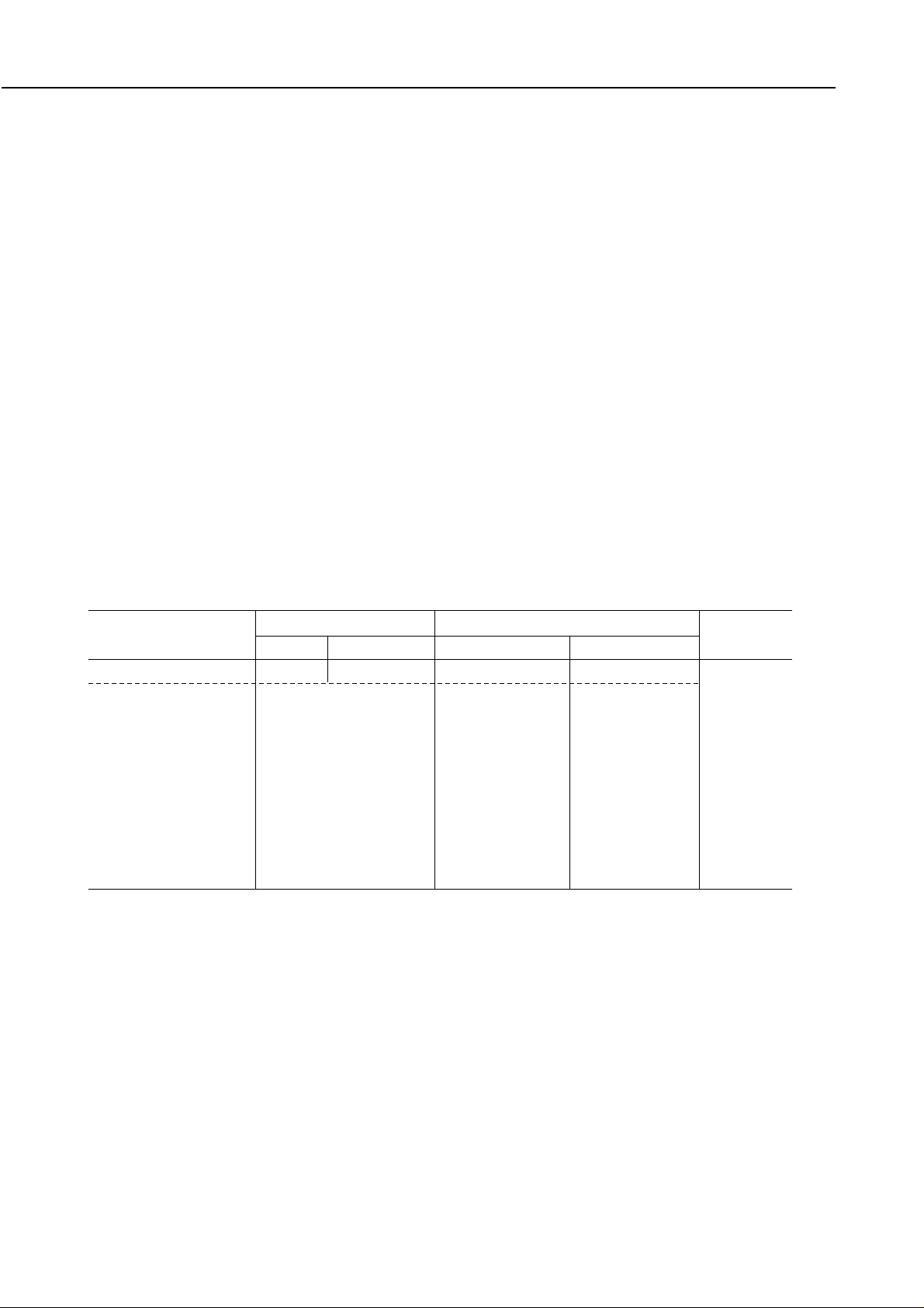
12. Number of columns printed
Mode Pitch cpl *
LQ mode 10 cpi 10 cpi 80 cpl
10 cpi doublewide 5 cpi 40 cpl
10 cpi condensed 17 cpi 137 cpl
10 cpi condensed-doublewide 8.5 cpi 68 cpl
12 cpi 12 cpi 96 cpl
12 cpi doublewide 6 cpi 48 cpl
12 cpi condensed 20 cpi 160 cpl
12 cpi condensed-doublewide 10 cpi 80 cpl
15 cpi 15 cpi 120 cpl
15 cpi doublewide 7.5 cpi 60 cpl
Proportional spacing PS Varies
BJ mode 10 cpi 10 cpi 80 cpl
10 cpi doublewide 5 cpi 40 cpl
10 cpi condensed 17 cpi 137 cpl
10 cpi condensed-doublewide 8.5 cpi 68 cpl
12 cpi 12 cpi 96 cpl
12 cpi doublewide 6 cpi 48 cpl
Proportional spacing PS Varies
* cpl: characters per line
13. Bit image
Vertical: 8, 24 and 48 dots
Horizontal: 60, 120, 180, 240, 360 and 720* dpi
* In smoothing mode or when using the Canon driver.
14. Buffer
Receive buffer Download buffer
LQ mode 22 kB 32 kB
BJ mode 22 kB 0 kB
15. Interface
IEEE1284 compatible parallel interface
2-9

Part 2: Product Specifications
✕ 231.6 mm D ✕ 203 mm H
22. Weight
Approximately 3.5 kg (7.7 lbs) (including BJ cartridge)
During operation During storage
Temperature 5°C to 35°C 0°C to 35°C
(41°F to 95°F) (32°F to 95°F)
Humidity 10% to 90%RH 5% to 95%RH
(no condensation) (no condensation)
Voltage/Frequency Power consumption Stand-by status
USA/Canada AC 120V 60 Hz
UK/Australia AC 240V 50 Hz Max. 30 W Max. 4 W
Europe AC 230V 50 Hz
16. BJ cartridge
Color BJ cartridge (Multi Drop)
Type: Color BJ cartridge with replaceable ink cartridges
Print head: 136 nozzles (vertically-lined) Bk (64 nozzles) + Y, M, C (24 nozzles x 3)
Ink colors: Black, cyan, magenta, yellow
Service life:
Approximately 160 pages (in the HQ mode with 1500 character pattern) with a black cartridge
Approximately 90 pages (in the HQ mode) with a color cartridge (7.5% duty per color pattern)
Weight: Approximately 85 g (3.0 oz) (including black and color ink tanks)
Black BJ cartridge
Type: Black BJ cartridge with integrated ink
Print head: 128 nozzles (vertically-lined)
Ink color: Black
Service life: Approximately 700 pages (in the HQ mode); cartridge
Weight: Approximately 85 g (3.0 oz)
Photo BJ cartridge (Multi Drop)
Type: Color BJ cartridge with integrated ink
Print head: 136 nozzles (vertically-lined) Bk (64 nozzles) + Y, M, C (24 nozzles x 3)
Ink colors: Black, cyan, magenta, yellow
Service life: Approximately 25 pages (in the Photo mode); cartridge
Weight: Approximately 74 g (2.8 oz)
BJC-4400
17. Sensor functions
Paper out: Provided
Installation of cartridge: Provided
BJ cartridge/Scanner cartridge identification: Provided
Waste ink amount: Provided
Ink out: None
Paper width: None
18. Acoustic noise level
Approximately 45dB (A)/ HQ 48dB (A)/ HS
(Sound pressure level: According to ISO 9296)
19. Ambient conditions
20. Power source
21. Dimensions
383 mm W
2-10
Part 2: Product Specifications
2.3 Paper Specifications
2.3.1 Paper size
Letter (8.5” ✕ 11”)
Legal (8.5” ✕ 14”)
A5 (148 mm ✕ 210 mm)
A4 (210 mm ✕ 297 mm)
Commercial number 10 envelope (9.5” ✕ 4.1”)
European DL-size (220 mm ✕ 110 mm)
2.3.2 Paper type (Recommended)
Plain paper
Bubble jet paper (Canon LC-301))
Envelope (Commercial number 10 or European DL)
Transparencies (Canon transparency film CF-102)
BPF (Canon back print film BF-102)
Glossy photo paper (Canon glossy paper GP-201)
High gloss paper (Canon high gloss Film HG-101)
Fabric (Fabric sheet FS-101)
Banner (Banner paper)
T-shirt transfer (Canon T-shirt Transfer TR-201)
BJC-4400
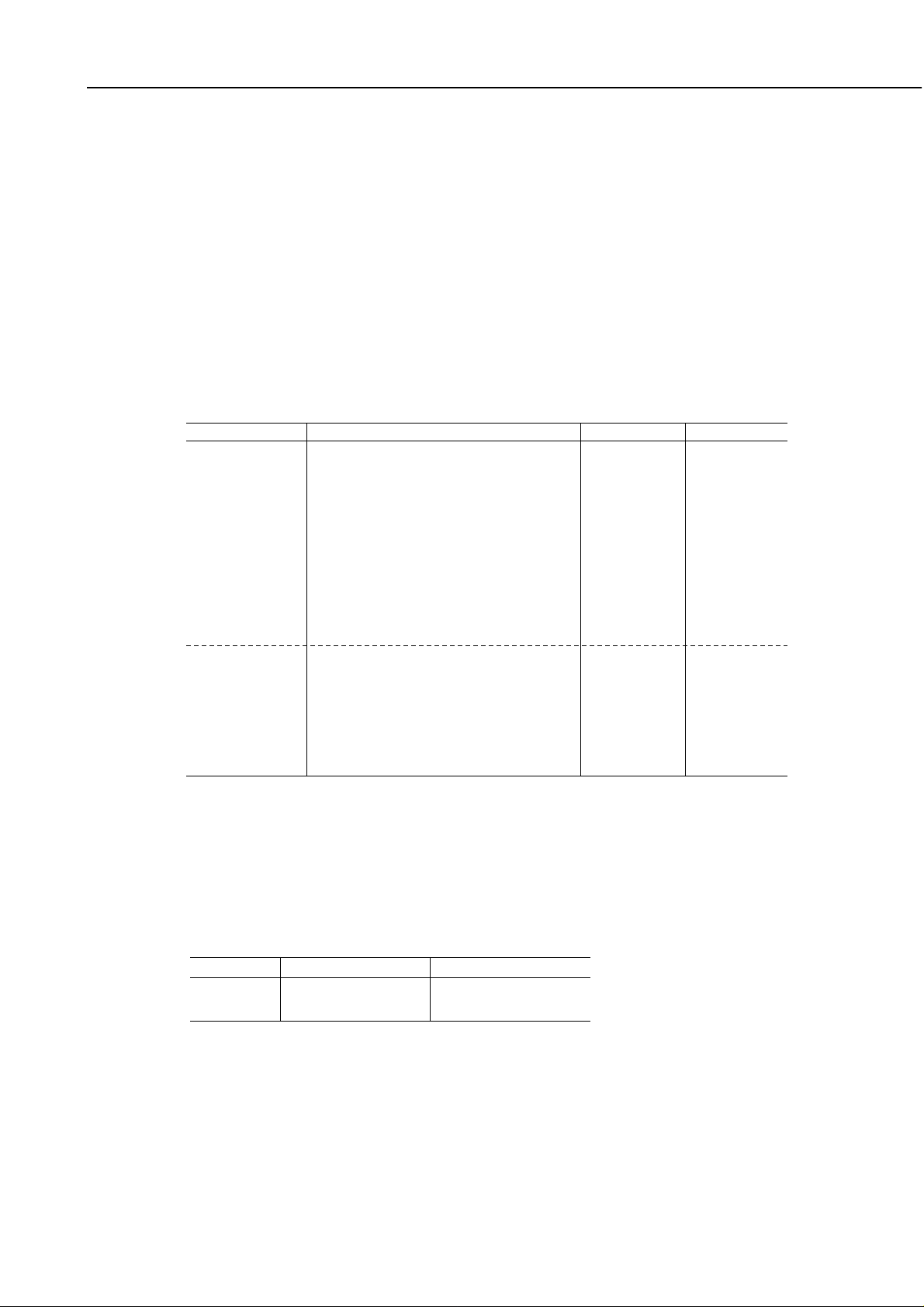
2.3.3 Print paper
Media Thickness Lever Paper Feed Flap
Black Color/Photo Method Limit Position
Plain paper Left Center Sheet feeder 10 mm Flat
High resolution paper Center Sheet feeder 10 mm Upright
Envelopes Right Sheet feeder 10 Flat
Transparencies Center Sheet feeder 50 sheets Upright
Back print film Center Sheet feeder 10 sheets Upright
Glossy photo paper Center Sheet feeder 1 sheet Upright
Banner paper Right Sheet feeder 1 sheet Upright
Fabric sheet Right Sheet feeder 1 sheet Upright
High gloss film Center Manual feed slot 1 sheet*1 Upright
T-shirt transfer Right Sheet feeder 1 sheet Flat
2-12
Part 3: Operating Instructions
BJC-4400
3-2
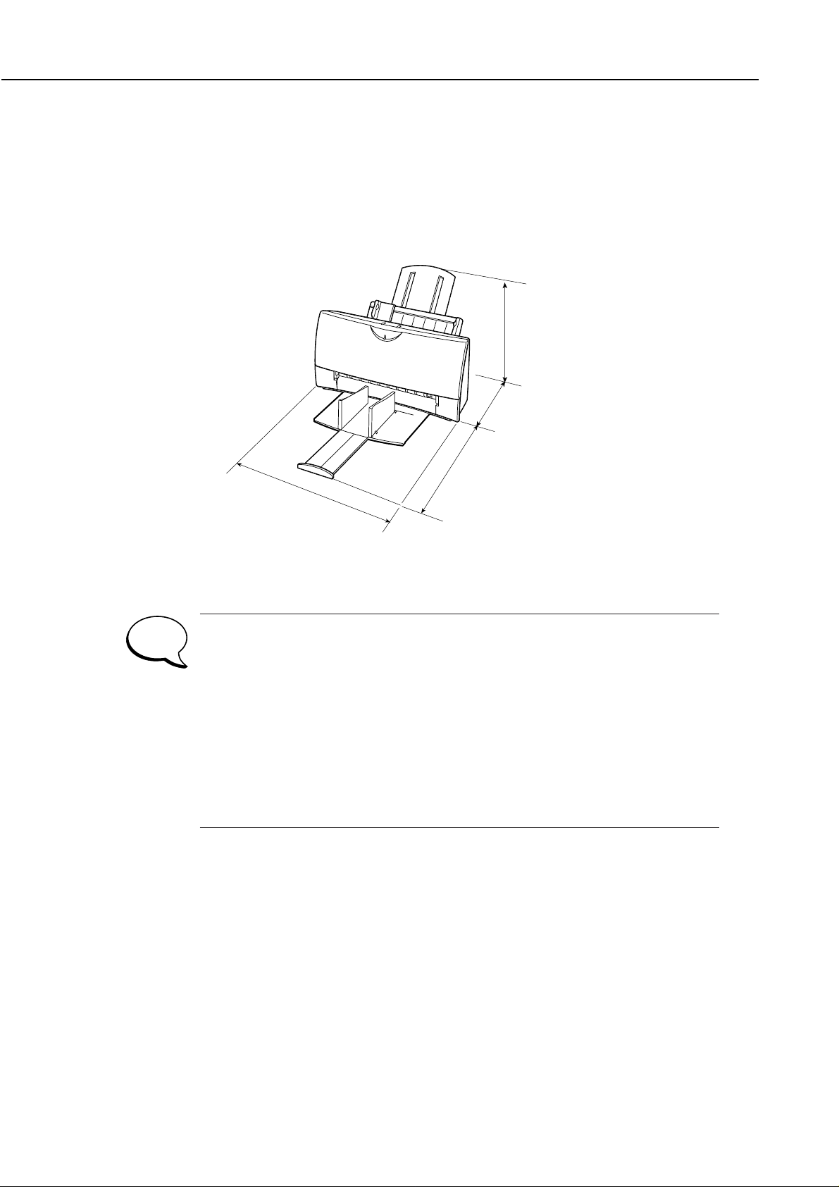
1.2 Printer Dimensions
The printer’s dimensions are shown below. Allow enough space for the printer to be used with ease.
For banner printing leave a space about the size of an A4-size paper in front of the printer. Also allow
enough space at the back of the printer to set the banner paper.
· Do not place the printer in excessive heat or humidity.
· Operate the printer under the following conditions:
Ambient temperature: 5°C to 35°C
Relative humidity: 10% to 90% (no condensation)
· Do not place the printer in direct sunlight.
· Do not place the printer near a device containing a magnet or that generates a magnetic
field.
· Place the printer on a level and stable surface.
· Do not place the printer in areas subject to vibration.
· Keep the printer clean.
· When moving the printer, hold both ends.
Figure 3-2 Printer Dimension
281 mm
268 mm
NOTE
304 mm
383 mm
Part 3: Operating Instructions
Plain paper Left Center Sheet feeder 10 mm Flat
High resolution paper Center Sheet feeder 10 mm Upright
Envelopes Right Sheet feeder 10 envelopes Flat
Transparencies Center Sheet feeder 50 sheets Upright
Back print film Center Sheet feeder 10 sheets Upright
Glossy photo paper Center Sheet feeder 1 sheet Upright
Banner paper Right Sheet feeder 1 sheet Upright
Fabric sheet Right Sheet feeder 1 sheet Upright
High gloss film Center Manual feed slot 1 sheet
*1
Upright
T-shirt Transfer Right Sheet feeder 1 sheet Flat
TABLE 3-1 QUICK REFERENCE FOR SETTING
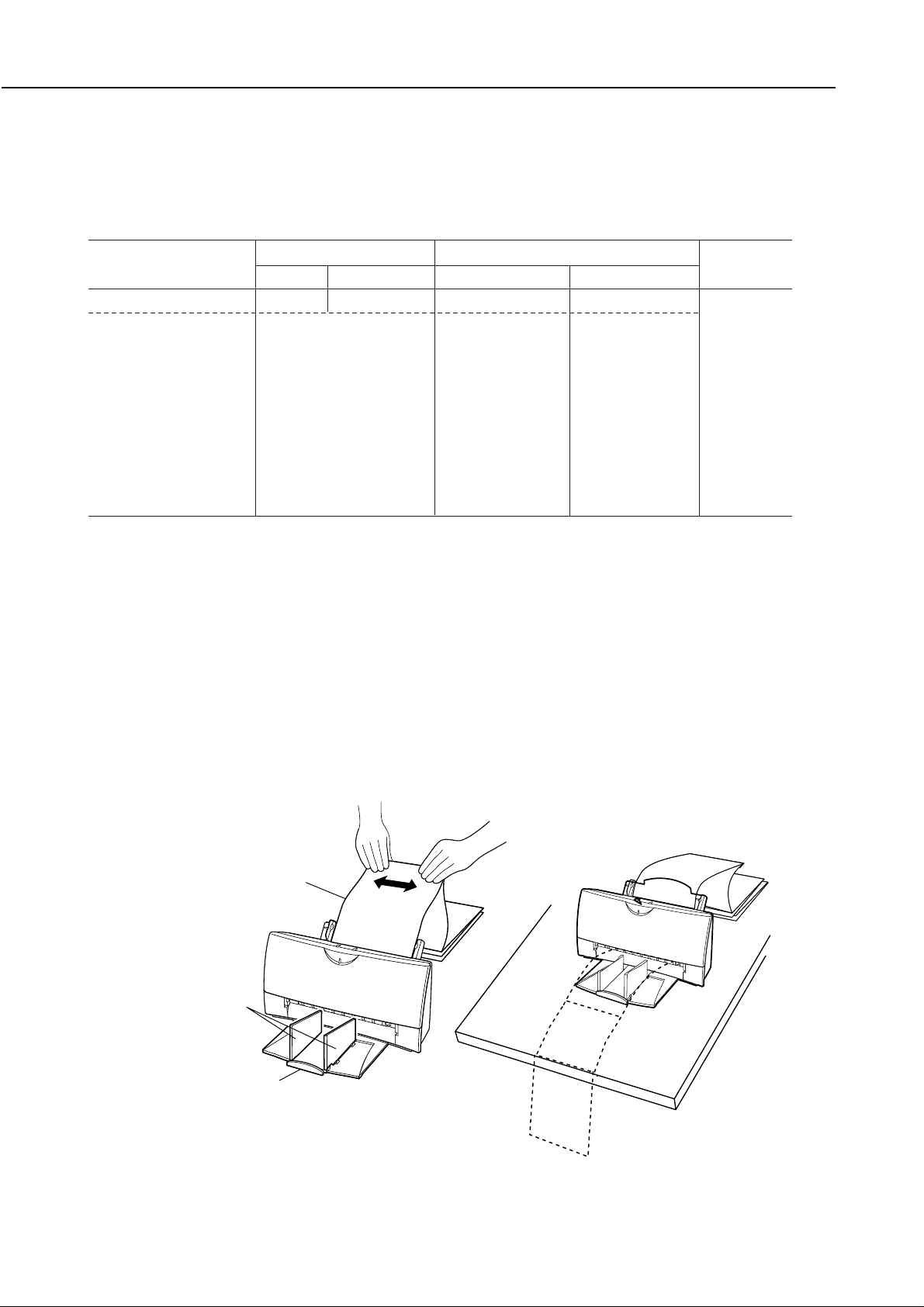
Figure 3-12 Banner Print
1.5 Paper Settings
For optimum printing, the printer has various paper settings to suit various types of paper. Set the paper
selection lever before loading the paper.
Media Thickness Lever Paper Feed Flap
Black Color/Photo Method Limit Position
BJC-4400
*1 Slide one sheet all the way into the manual feeding slot.
1.6 Banner Print
When printing on banner paper, lower the paper support and set the paper delivery flap to the upright
position. To avoid misfeeding, put a light crease between the first and second page and set the first page in
the sheet feeder. Place the rest of the banner paper behind the printer. Do not use the manual feeding slot
to avoid skewing.
Each top margin for banner printing is set at 0mm. However, to avoid printing on the platen, printing will
start 3mm from the initial top margin. Set an extra sheet at the end in case the bottom edge is not printed
on the last page.
Banner printing uses a large amount of ink. To avoid ink shortage, use of a new ink cartridge before
banner printing is recommended.
Banner Paper
Paper Delivery Flap
Output Tray Extention Guide
3-10
Part 3: Operating Instructions
3-11
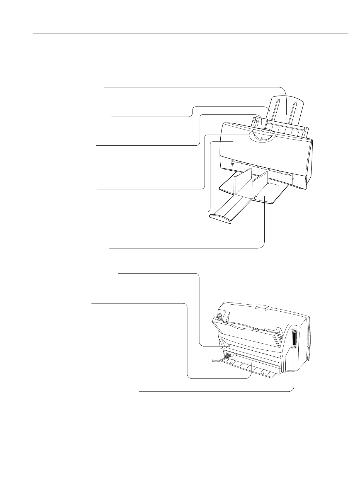
7 Name of the Parts and Their Functions
The different parts of the printer and their functions are shown below.
BJC-4400
Paper Support
Cut Sheet Feeder
Holds a stack of approximately 100 cut
sheets (64g/cm) for automatic feeding.
Paper Guide
Aligns the cut sheets in the cut sheet feeder
according to the paper size. A maximum
paper width of 241 mm (9.64 in.) can be set.
Autofeeds banner paper and scanning
document.
Control Panel
Front Cover
Paper Output Tray
Manual Feeding Slot
AC Adapter
Parallel Interface Connector
2
See the next page.
Open to install or remove the cartridge, set
the paper thickness lever, or remove the jams
paper.
Pulls out to receive the printed sheets.
Use for feeding media
manually.
Installed on the rear of the
printer, the AC adapter
supplies power from the power
outlet to the printer.
Depending on the location of
purchase, the power cable is
permanently attached to the
AC adapter where as in some
areas the power cable is
detachable.
Connects the printer to the
parallel port on the computer.
Supports the stack of paper loaded in the
cut sheet feeder.
Figure 3-13 Name of the Parts and Their Functions
4-1
BJC-4400
Part 4: Technical Reference
1. OVERVIEW
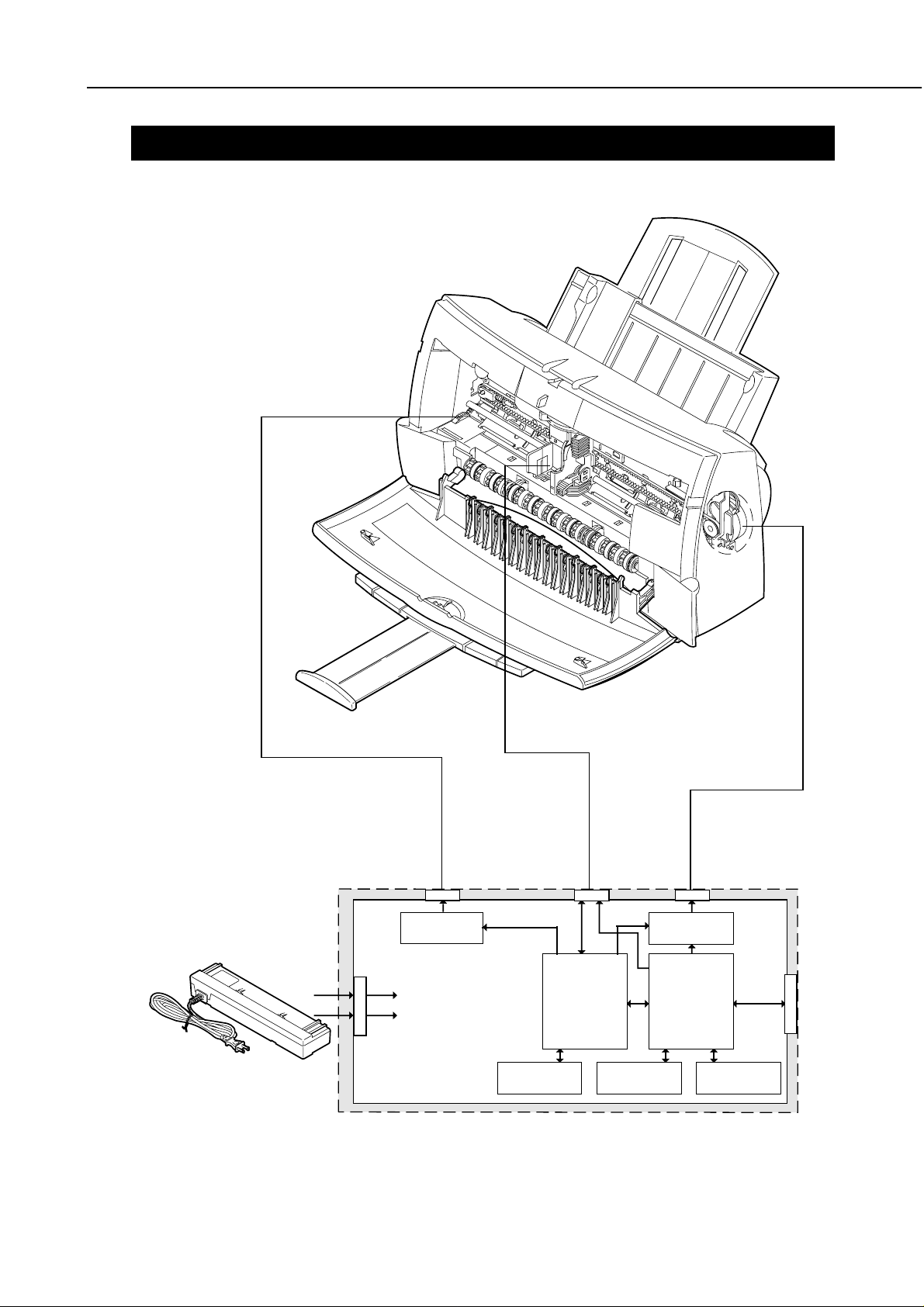
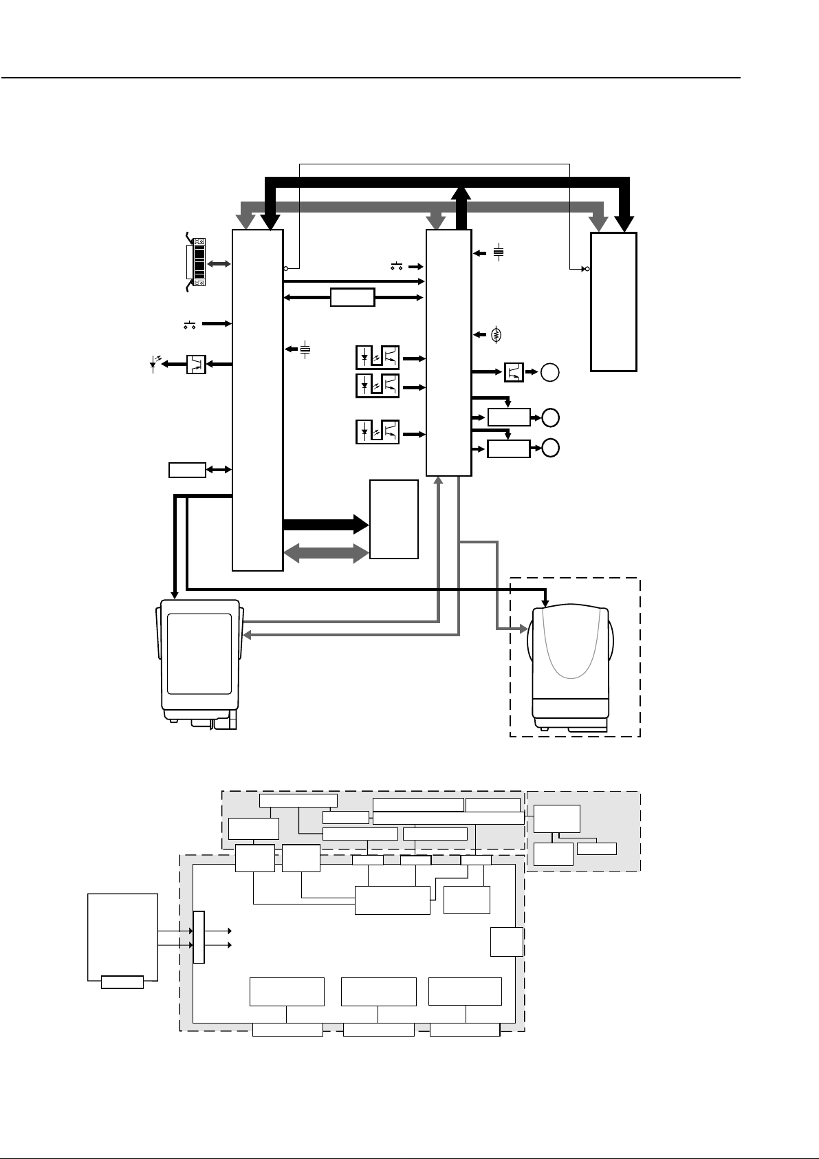
1.1 Printer Diagram
Figure 4-1 Printer Diagram
Paper Feed Motor
Logic Board
VH (+24.0VDC)
J1
Vcc (+5VDC)
J4
Paper Feed
Motor Driver
Carriage
· BJ Cartridge/ Scanner Cartridge
· Home Position Sensor
J5
Carriage Motor
MPU
Control/CG ROM
Carriage Motor
J3
Driver
Printer
Controller
EEPROMDRAM
J2
I/F

The electrical system functions are handled by the logic section or power supply.
The logic section converts the data from the interface into print signals or printer operation signals and
drives the BJ cartridge and motors while monitoring the status of the sensors.
The power supply unit consists of a built in AC adapter which provides DC output to the logic board,
motors and head etc.When DC input power from the AC adapter is being supplied, all of the hardware
components are active except for the following which are inactive: All buttons except the
POWER
button,
and the photo interrupter's sensor.
4-37
BJC-4400
Part 4: Technical Reference
Figure 4-27 Printer Electrical System
4. PRINTER ELECTRICAL SYSTEM
4.1 Overview
Carriage Ribbon Cable
RESUME Switch
DRAM
POWER Switch
Printer Controller
Carriage Motor
J3
J5
Carriage Motor Driver
Pick-up Roller Sensor
AC Adapter
CARTRIDGE Switch
Control/CG ROM
Beeper
J1
J2
J4
MPU
Paper Feed Motor
Paper Feed Motor Driver
Paper End Sensor
Part 4: Technical Reference
Figure 4-28 Logic Board Block Diagram
4.2 Logic Section
4.2.1 Logic section block diagram
BJC-4400
RESUME
CARTRIDGE
ERROR
POWER
HCLOCK
HDATA
HLATCH
BENB1 to 3
HENB0 to 3
ODDENB
EVENENB
Parallel Interface
1 Kbit
EEPROM
MCH0
ID0,1
HRES
BJ Cartridge
Black BJ Cartridge
heater (128 nozzles)
Color BJ Cartridge
heater (136 nozzles)
•
Sub-heater
•
Temperature control
heater
•
Head temperature
sensor
•
Rank resistor
Transistor
SCLOCK
SDATA
SLATCH
COM 0 to 3
C.CHK
C.CHA
A0 to 23
AD0 to 15
CS0
INT 0 to 3
RES
PC2 to 3
PB0
PB1
Printer Controller
PE4 to 7
MA0 to 9
MD0 to 15
VHC,CVDC
Address Bus
A/Data Bus
Reset IC
22.11MHz
DRAM Bus
MA0 to 9
MD0 to 15
A0 to 23
AD0 to 15
POWER Switch
Pickup Roller Sensor
PS2
Paper End Sensor
PS1
Home Position Sensor
DRAM
4-Mbit
A0 to 9
DO 1 to 16
A0 to 15
P87
PB0,PB1
PB4,PB5
RES
P33
P41
P60 to 63
P40
P90 to 93
P35,36
AN1,3
AD16 to 23
AN0
MPU
P71
P72
P73
P94
P95
P42
P66
20MHz
Temp. Sensor
(TH1)
Transistor
Driver IC
Driver IC
HVH
H VDD
CE
Beeper
BZ
PM
Carriage Motor
PM
Paper Feed Motor
Scanner Cartridge
(Option)
•
Scanner controller
•
CCD
•
LEDs (R,G,B)
A0 to 18
D0 to 15
Control/CG ROM
8-Mbit
AC Adapter
AC Inlet
MECHANISM SECTION
Paper Feed Roller
Sheet
Feeder
Pick-up
Roller
Sensor
Paper
End
Sensor
VH (+24.0VDC)
J1
Vcc (+5VDC)
Bi-directional
Interface Control
J2
ELECTRICAL SECTION
Figure 4-29 Printer Block Diagram
Purge Unit
Home Position Sensor
Paper Feed Motor
J4
Mechanism
Control
Logic Board
Indicator Control
Indicators
4-38
Carriage
Carriage Motor
J3
Cartridge
Control
Switch Detection
Control Buttons
BJ Cartridge
J5
Temp.
Sensor
(TH1)
Scanner Cartridge (Option)
Scanner
Controller
LEDs
(R,G,B)
CCD

BJC-4400
Part 4: Technical Reference
4.2.2 Logic section components
1) MPU (IC2)
The MPU contains a 16-bit CPU, 1K-bit RAM, 24-bit address bus port, 16-bit data bus port, stepping
motor controller, interrupter controller, A-D converter, I/O ports, and other components.
Built-in CPU
The 16-bit CPU operates in synchronization with a 20 MHz external clock input.
Address bus
The 24-bit address bus port is connected to an 8 M-bit control/CG ROM and printer controller. The
controller/CG ROM synchronizes with the read signals output by the MPU and the 20 MHz clock
signal. The printer controller then selects the chip.
Data bus
Like the address bus, the 16-bit data bus port is connected to the 8 M-bit control/CG ROM and printer
controller.
Stepping motor controller
The stepping motor controller outputs double 1-2 phase exciter drive signals to both the carriage motor
driver and paper feed motor driver.
The stepping motor controller can switch the the 4-step peak current value of both motor driver.
Interrupt controller
For external interruption, the MPU has ports P80, 81, 84, 85, and 87 to receive the POWER button
on/off switching, data reception, initial interrupt request, receive buffer-full warning, and other signals.
The MPU executes interrupt processing for the respective signals.
A-D converter
The following analog signals are detected after they pass through the built-in A-D converter:
AN0: The printer's internal temperature is detected by the thermistor on the logic board.
AN1: The head temperature is detected by the head temperature sensor in the BJ cartridge.
AN3: The head rank is detected by the rank resistor in the BJ cartridge.
I/O port
The setting status determined by the head ID, paper end sensor, home position sensor, and pick-up
roller sensor are input through the input ports. The buzzer, BJ cartridge detection, head-driving voltage
control, and other signals are output from the output ports.
4-39

2) Printer controller (IC3)
The printer controller contains the interface controller, print head controller, buffer controller, DRAM
controller, EEPROM controller, I/O ports, etc. It operates in synchronization with an external 22.11
MHz external clock input.
Interface controller
The interface controller receives from the computer, 8-bit parallel data which is synchronized with the
data strobe pulse (STROBE) through the BUSY/ACKNLG handshake. It also controls other interface
signals.
The data received through the interface is stored in the DRAM's receive buffer and analyzed by the
MPU.
When the printer initialization signal INIT is input through the interface to the printer controller, the
printer controller outputs a BUSY signal. Also, after INT1 is output to the MPU and print data in the
print buffer is printed, the printer is initialized.
DRAM controller
The DRAM controller is a DRAM-specific bus separated from the MPU bus. It controls the 4 M bit
DRAM's 10-bit address/16-bit data bus and also executes read/write control, RAS/CAS control, and
refresh control.
Buffer controller
The buffer controller automatically writes the received data to the receive buffer on the DRAM,
manages the receive buffer's remaining capacity, automatically reads the print buffer, and clears the data
after it is read.
Print head controller
The print head controller converts the print data read from the DRAM's print buffer from parallel to
serial and sends it to the print head. At the same time, the printed dots are counted for the variable
control of the Heat-enable (H ENB) signal pulse width.
The head-driving signals consist of the block enable signals (B ENB 1, 2, 3), odd/even enable signals
(OddENB/EvenENB), and heat enable signals (H ENB 0, 1, 2, 3). The block enable signals and
odd/even enable signals specify the block for time-shared drive. The heat enable signals control the
eject heater's conduction time.
I/O port
The I/O ports sense the
RESUME
and
CARTRIDGE
buttons' input status. The output ports control
the lighting of the
POWER
and
ERROR
indicators.
Part 4: Technical Reference
4-40
BJC-4400

BJC-4400
Part 4: Technical Reference
3) Control/CG ROM (IC4)
The 8 M-bit control/CG ROM contains the program and bitmap font data for printer control.
4) DRAM (IC7)
Controlled by the printer controller, the 4 M-bit DRAM is used as a receive buffer, download buffer,
print buffer, and working area.
5) Reset IC (IC1)
This IC detects the power voltage when turning on the power or instantaneous power failure.
6) EEPROM (IC6)
Controlled by the printer controller, the 1 K-bit EEPROM (Electrically Erasable and Programmable
ROM) stores various function settings, the total count of printed sheets, and the total waste ink amount.
7) Carriage motor driver (IC12) / Paper feed motor driver (IC13)
The carriage motor driver which is controlled by the MPU drives both the carriage motor and the paper
feed motor which in turn are controlled by an double 1-2 phase exciter with a fixed current bipolar
drive. Upon receiving the switching signal from the MPU, the peak current value can be set
individually into 4 steps for phase A and B. By doing so, it ensures smooth operation of the motors.
10K,1/8W
LF10A
LF11A
LF10B
LF11B
100µ,35W
RA3
C202
0.51,1/4W
R70
0.51,1/4W
R71
+5V
567
8
431
2
N1608Z300T01
FB102
+5V
+5V
C60
0.1µ,25W
C61
FB101
N1608Z300T01
J4
1
A
2
A
3
B
4
B
R72
10K,1/16W
02DZ3.0Z
ZD18
4700p,50V
Paper Feed
R73
360,1/10W
2
1
Motor
Approx.6Ω/
02DZ2.0Z
phase
ZD19
LFVREF
3
Q13
FA1L4M
VM
LFA
LFB
C203
0.1µ,50W
VM-G
Paper Feed
Motor Driver
1
NC
2
VssA
3
Out1
4
NC
5
RsA
6
NC
7
IC13
Out2
8
Out3
9
NC
10
RsB
11
NC
12
Out4
13
VssB
14
NC
28
Vcc
27
INA
26
IOA
25
IIA
24
VsA
23
VrefA
22
LG
21
C/R
20
VrefB
19
VsB
18
IIB
17
IOB
16
INB
15
Vcc
10K,1/8W
CR10A
CR11A
CR10B
CR11B
100µ,35W
RA4
C205
CRA
CRB
+5V
8
3
VM
0.51,1/4W
R74
0.51,1/4W
R75
567
124
C206
0.1µ,50W
VM-G
Carriage Motor
Driver
1
Vcc
NC
2
INA
VssA
3
IOA
Out1
4
IIA
NC
5
VsA
RsA
6
VrefA
NC
IC12
7
LG
Out2
8
C/R
Out3
9
VrefB
NC
10
VsB
RsB
11
12
13
14
IIB
NC
IOB
Out4
INB
VssB
Vcc
NC
+5V
28
27
26
25
24
23
22
21
20
19
18
17
16
15
+5V
C62
R76
0.1µ,25W
02DZ3.0Z
ZD20
C63
J3
1
A
2
A
3
B
4
B
R77
10K,1/16W
360,1/10W
02DZ2.0Z
ZD21
2
CRVREF
3
1
4700p,50V
Q14
FA1L4M
Carriage Motor
Approx.6Ω/
phase
Figure 4-30 Motor-Driving Circuit
4-41
Part 5: Maintenance
BJC-4400
5-3
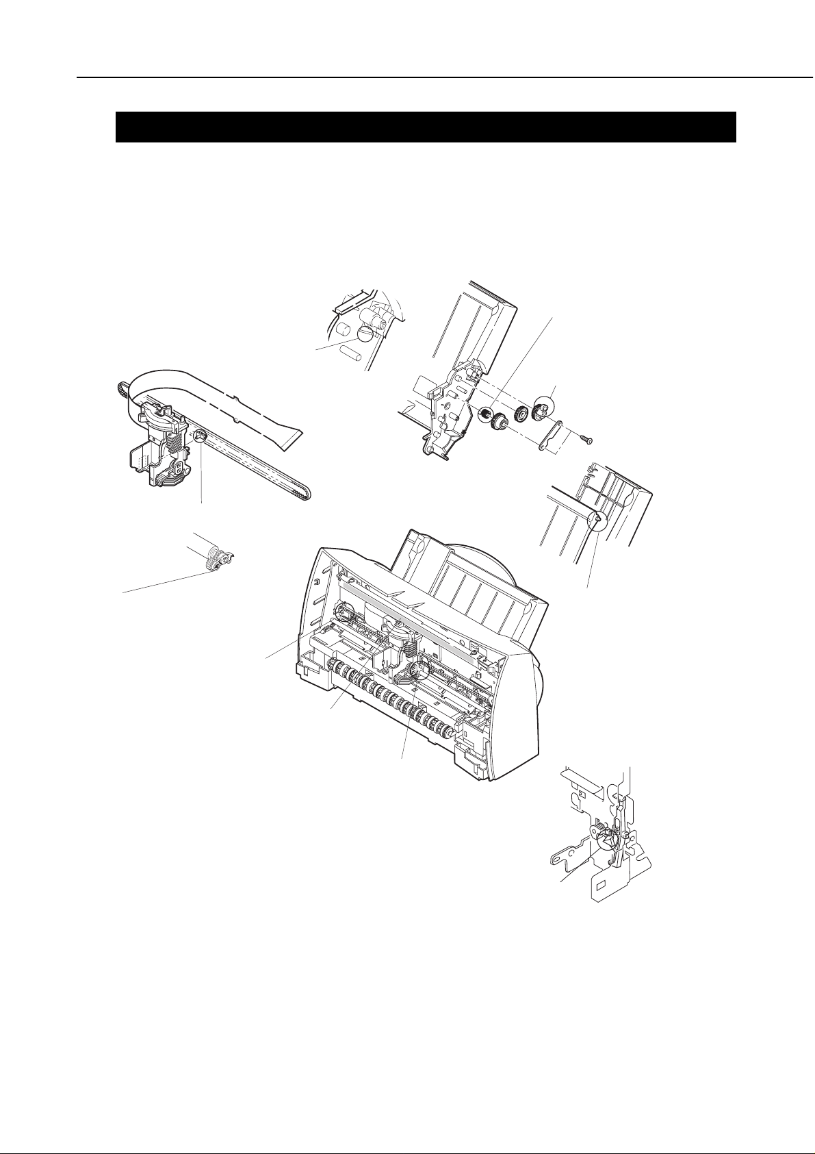
3. GREASE APPLICATION
Use the special tool to apply grease at the points shown below.
Rubbing Section of Carriage
Hook and Carriage:
About 12 mg (FLOIL G311S)
Rubbing Section of Cam Gear
About 12mg (FLOIL G311S)
Rubbing Section of Clutch
Spring and Clutch Gear:
About 12 mg (FLOIL G311S)
Belt Holder:
About 20mg (FLOIL G311S)
Paper Lifting Plate :
About 6mg (FLOIL G311S)
Idler Roller Shaft Section:
About 6mg (FLOIL G311S)
Rubbing Section of Frame
and Paper Lifting Plate:
About 6 mg (FLOIL G311S)
Both Sides of Carriage Guide Frame:
About 80 to 120 mg (MOLYKOTE PG-641)
Rubbing Section of Carriage and Carriage Shaft:
About 135 to 165 mg (MOLYKOTE PG-641)
Paper Feed Motor Drive
Transmission:
About 6mg (FLOIL G311S)
Figure 5-1 Grease Application Points
Part 5: Maintenance
1 HVG ... GND for head drive voltage VH
2 HVG ... GND for head drive voltage VH
3 HT0 IN Driver signal for temperature control heater
4 HT1 IN Driver signal for temperature control heater
5 HVH OUT Head driver voltage
6 HVH OUT Head driver voltage
7 W-HT OUT Drive signal for temperature control heater
8 INKS1 ... Not used
9 TOP IN Detection signal for rank resistance
10 DIODEA OUT Head temperature sensor (diode) anode
11 ID0 IN Cartridge detection and recognition signal
12 ID1 IN Cartridge detection and recognition signal
13 INKS2 IN/OUT Cartridge detection and recognition signal
14 HVss ... Head's logic drive voltage HVdd GND
15 HENB0(Y) OUT Heat enable
16 Even ENB OUT Even nozzle heat enable
17 HENB1(M) OUT Heat enable
18 HENB3(B) OUT Heat enable
19 Odd ENB OUT Odd nozzle heat enable
20 BENB1 OUT Block enable generation signal
21 BENB2 OUT Decoder output signal
22 BENB3 OUT
23 HVdd OUT IC drive voltage (+5 V)
24 HCLK OUT Print data transfer signal
25 HLATCH OUT Timing signal for print data to latch
26 HRES OUT Latch reset signal
27 HENB2(C) OUT
28 HDATA OUT Printing data
29 DIODEK IN Head temperature sensor (diode) cathode
30 HPO IN Home position sense High/ Low(sense)
31 HPG ... Ground
32 HPA OUT Photo LED drive
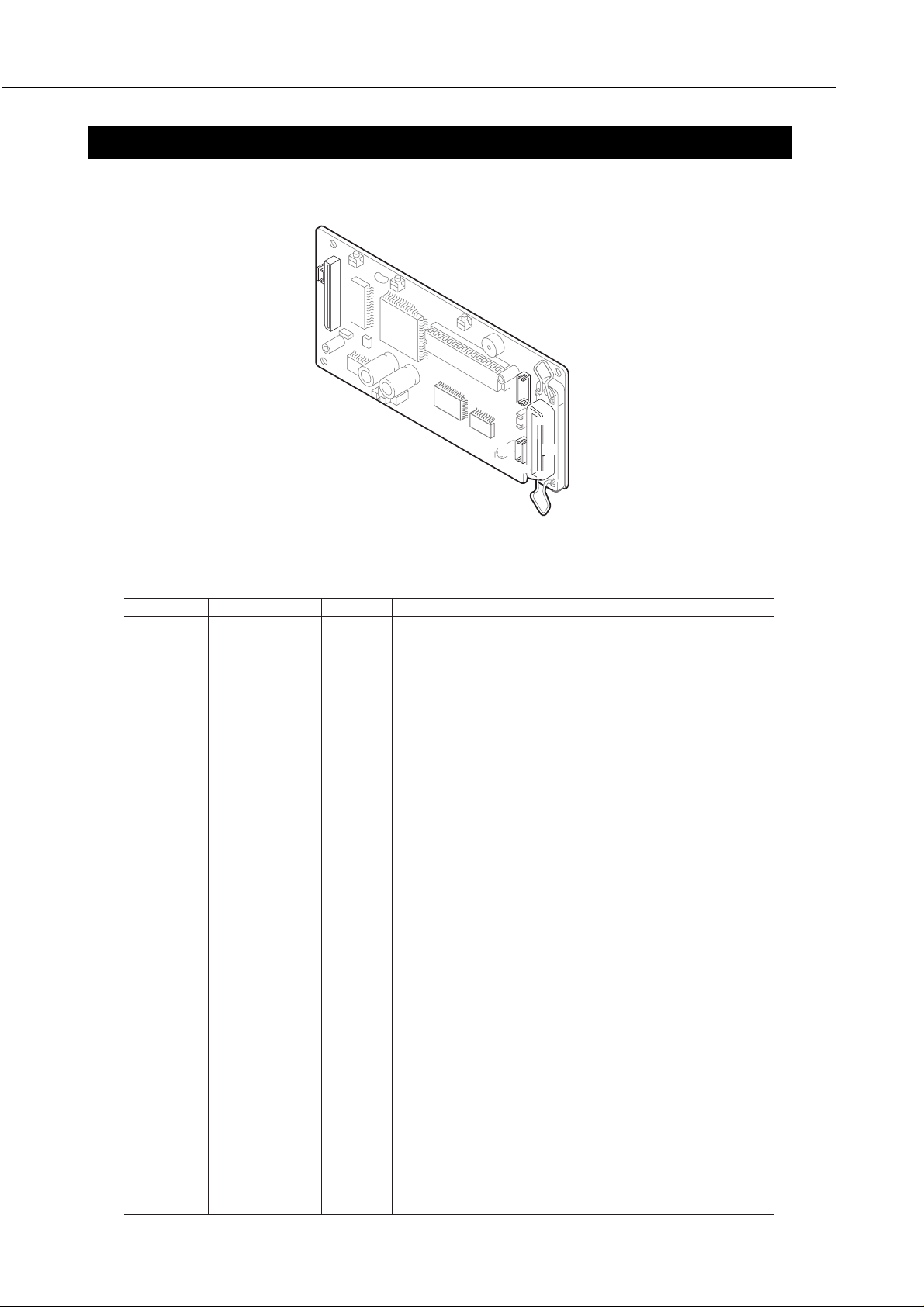
Figure 5-9 Logic Board
7. LOCATION & SIGNAL ASSIGNMENT
7.1 Logic Board
J3
BJC-4400
32
1
31
4
J5
2
1
5
J1
1
1
19
1
J2
J4
J5
5
18
36
J5 (Ribbon cable connector)
Pin No. Signal name IN/OUT Description
5-30
Part 5: Maintenance
BJC-4400
5-31
J3 (Carriage motor connector)
Pin No. Signal name IN/OUT Description
1 CRA OUT Carriage motor phase A
2 CRA OUT Carriage motor phase A
3 CRB OUT Carriage motor phase B
4 CRB OUT Carriage motor phase B
J4 (Paper feed motor connector)
Pin No. Signal name IN/OUT Description
1 LFB OUT Paper feed motor phase B
2 LFA OUT Paper feed motor phase A
3 VM ... Common
4 LFA OUT Paper feed motor phase A
5 LFB OUT Paper feed motor phase B
J1 (DC power connector)
Pin No. Signal name IN/OUT Description
1 Vcc IN +24 VDC
3 GND ... Ground
4 GND ... Ground
5 VH IN +5 VDC
J2 (Interface connector)
Pin No. Signal name IN/OUT Description
1 STROBE IN See Part 2 for details
2 DATA1 IN
3 DATA2 IN
4 DATA3 IN
5 DATA4 IN
6 DATA5 IN
7 DATA6 IN
8 DATA7 IN
9 DATA8 IN
10 ACKNLG OUT
11 BUSY OUT
12 P.E. OUT
13 SELECT OUT
14
AUTO FEED XT
IN
15 N.C ...
16 INIT IN
17 GND ...
18 N.C ...
19 STROBE-RET ...
20 DATA1-RET ...
21 DATA2-RET ...
22 DATA3-RET ...
23 DATA4-RET ...
24 DATA5-RET ...
25 DATA6-RET ...
26 DATA7-RET ...
27 DATA8-RET ...
28 ACKNLG-RET ...
29 BUSY-RET ...
30 P.E.-RET ...
31 INIT IN
32 ERROR OUT
33 GND ...
34 N.C ...
35 +5.0V ...
36 SELEC IIN IN
Part 5: Maintenance
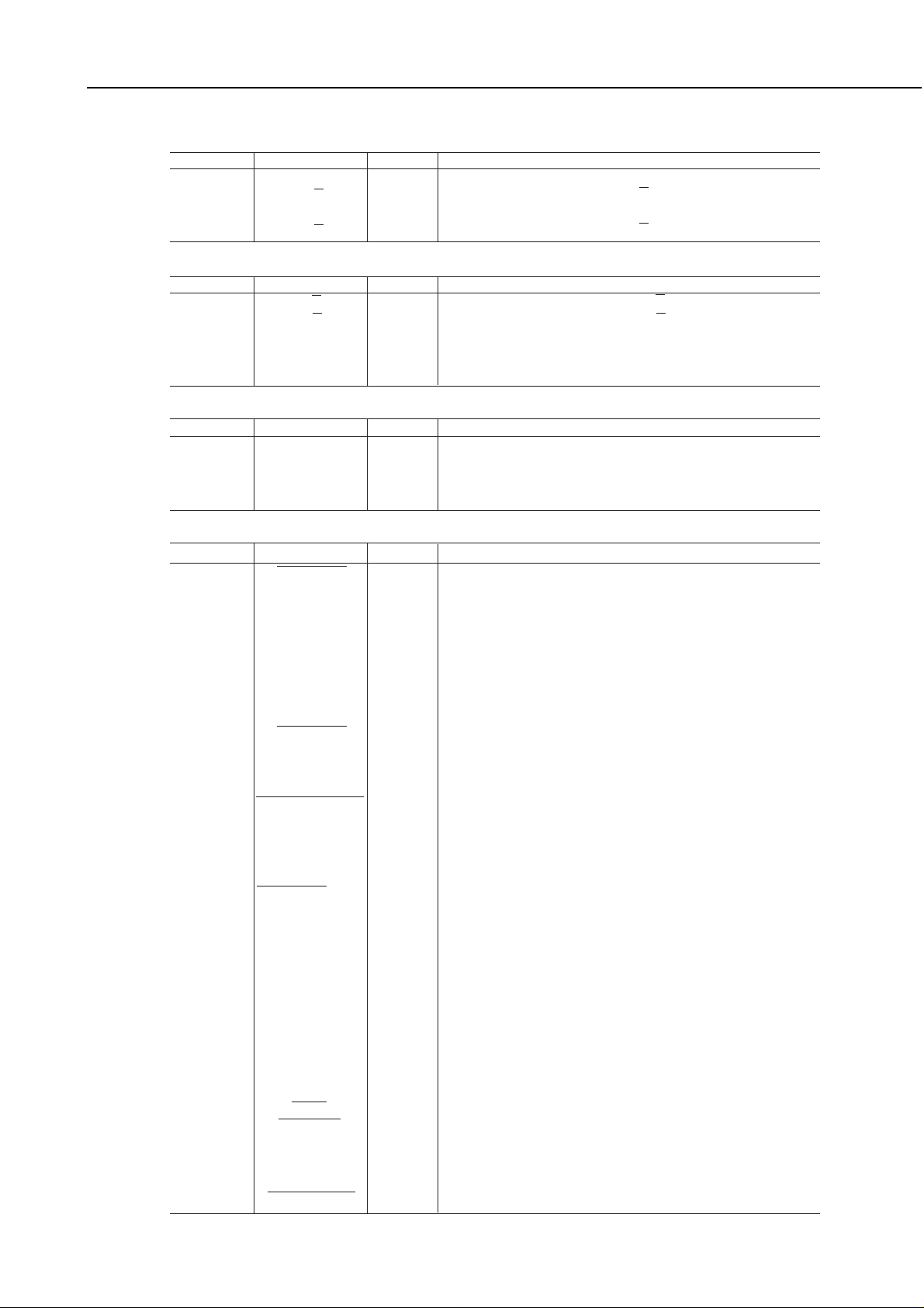
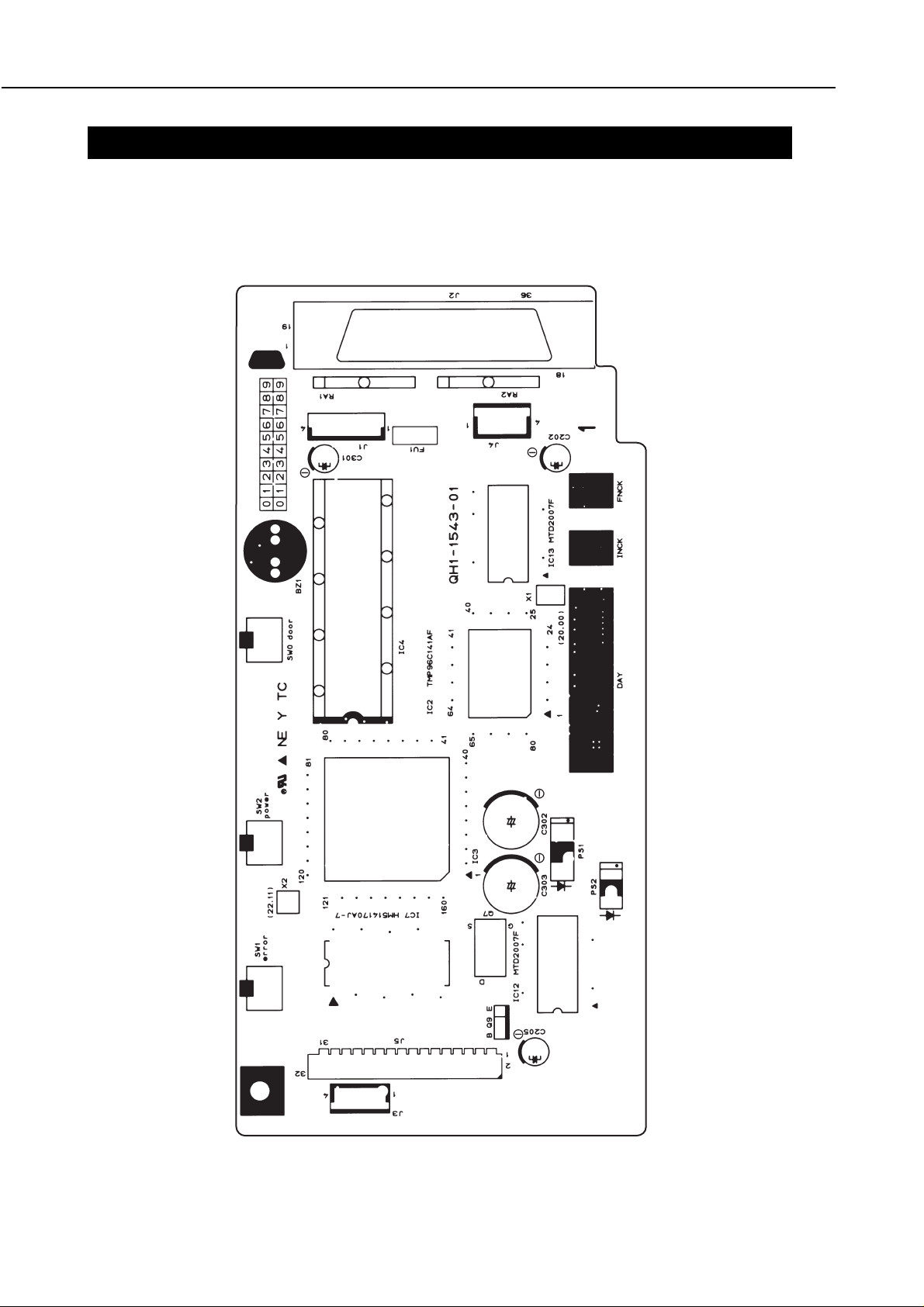
Figure 5-10 Logic Board (Top View)
8. CIRCUIT DIAGRAMS
8.1 Parts Layout
8.1.1 Logic board
BJC-4400
5-32
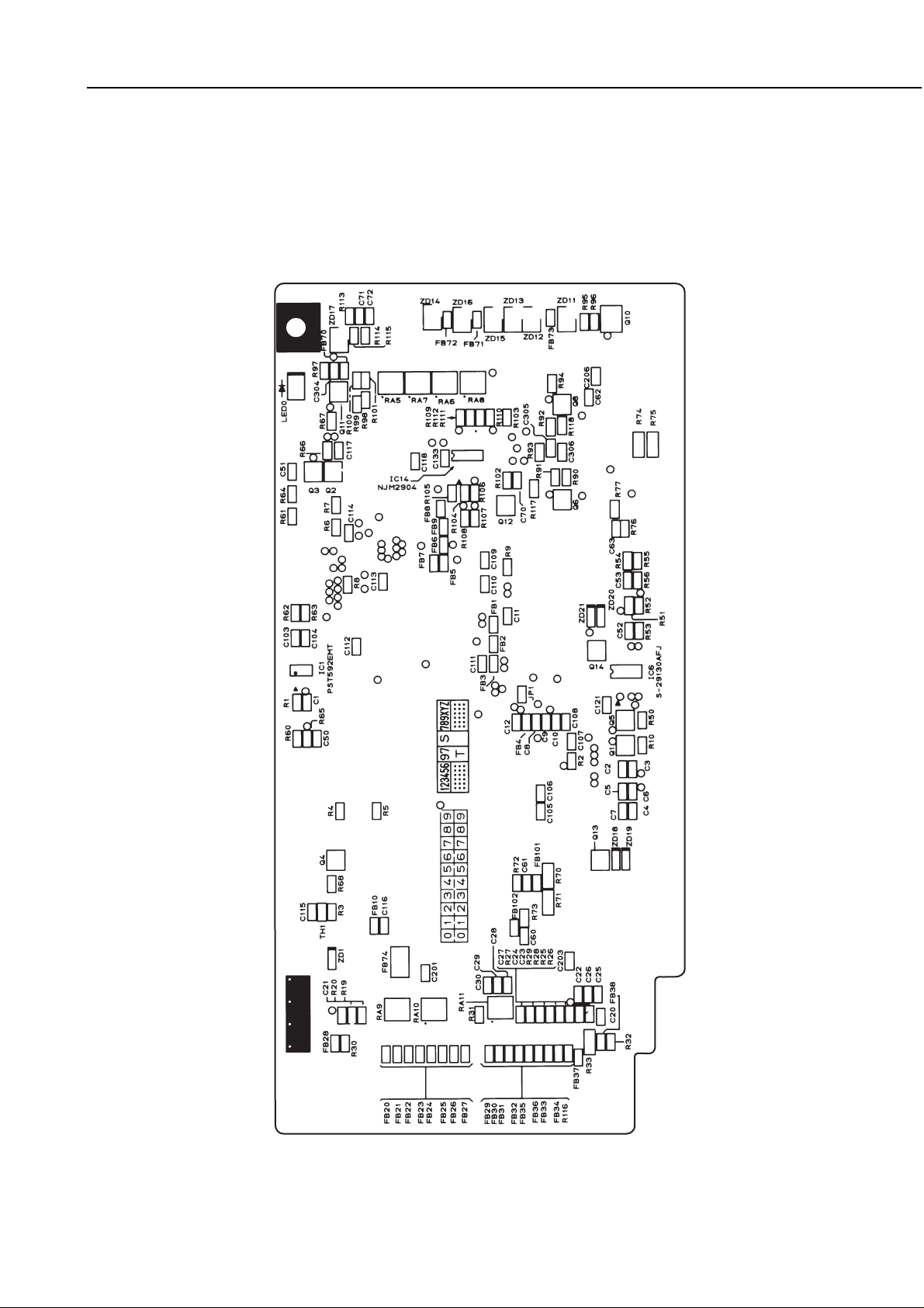
BJC-4400
Part 5: Maintenance
Figure 5-11 Logic Board (Bottom View)
5-33

Part 5: Maintenance
BJC-4400
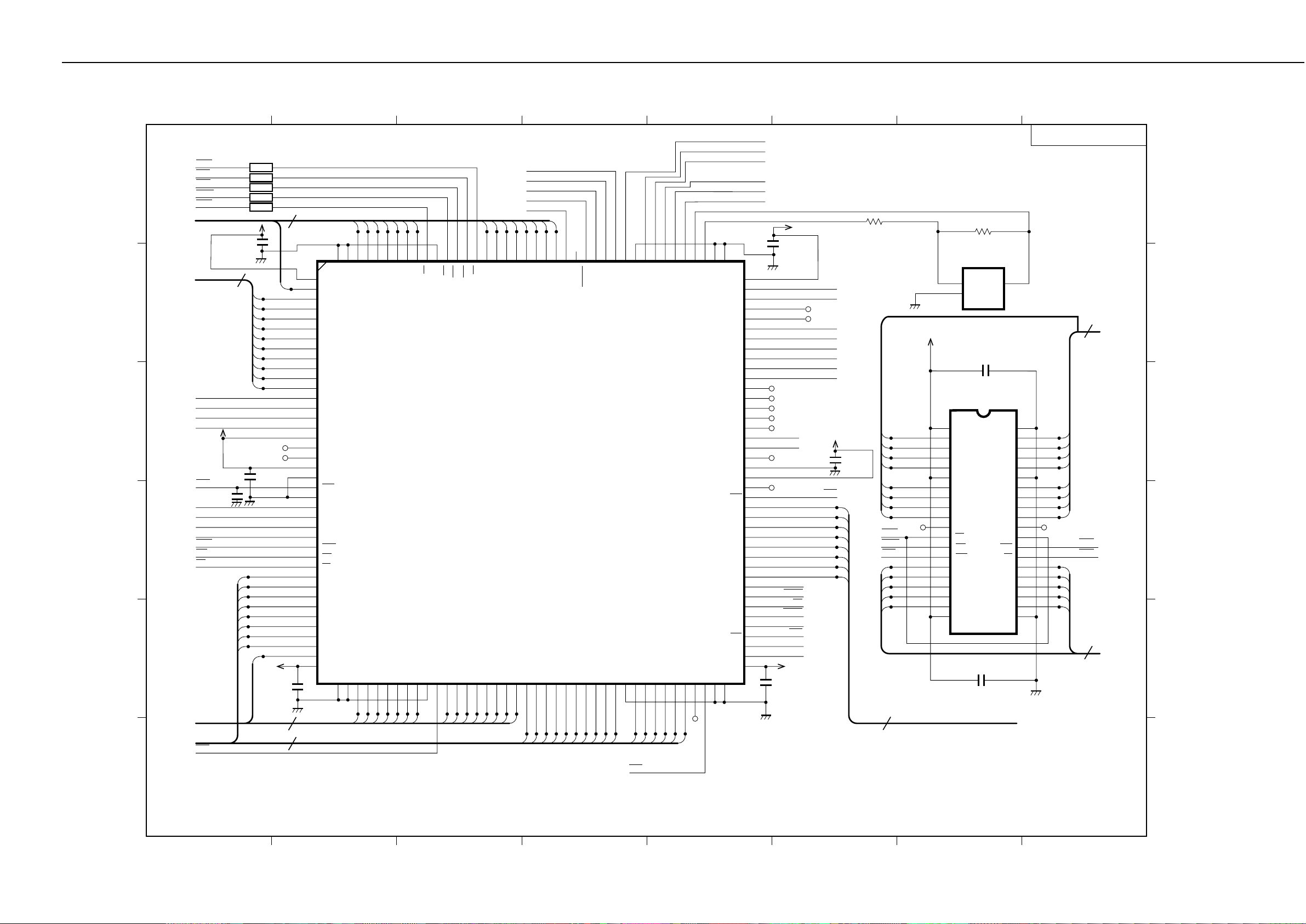
5-35
8.2 Circuit Diagrams
87654321
LOGIC BOARD 01
+5V
<03-A8>
<03-B7>
<03-F4>
<03-F4>
<03-F4>
<03-F4>
<05-C8>
<05-B8>
<03-E7>
<03-B7>
<03-D1>
<04-C8>
<03-D4>
<03-D4>
<02-C8>
<02-C8>
<02-C8>
<02-C8>
<04-D1>
<02-C8,
04-B1>
DTH
HRANK
CR10A
CR11A
CR10B
CR11B
IFC
SNC
CVDC
TOPC
CRVREF
BZ
CRA
CRB
INT0
INT2
C2
100p,50V
INT1
INT3
POWER
100p,50V
RES
0.1µ,25V
C10
1000p,50V
C6
C7
+5V
C3
100p,50V
+5V
Temperature
<03-B1>
C5
100p,50V
+5V
C4
100p,50V
10K,1/16W
Sensor
47K,1/16W,0.5%
LF VREF
CP9
CP4
CP5
R2
R3
C9
0.1µ,25V
C107
0.1µ,25V
C108
1000p,50V
1
P60
2
P61
3
P62
4
P63
5
P64
6
P65
7
P66
8
P67
9
P70
10
P71
11
P72
12
P73
13
P80
14
P81
15
P82
16
P83
17
P84
18
P85
19
P86
20
P87
21
NMI
22
WDO
23
RES
24
CLK
TH1
C8
0.01µ,50V
+5V
807978777675747372717069686766
Vss
Vcc
AGND
Vref
AN3
AN2
AN1
AN0
P42
P41
P40
P37
P36
P35
MPU
IC2
TMP96C141AF
QFP-80p
VssX1X2EAP90
252627282930313233343536373839
P91
P92
P93
P94
P95
ALE
Vcc
AD0
AD1
CP6
P34
AD2
2125chip
65
P33
HWR
WR
RD
A23
A22
A21
A20
A19
A18
A17
A16
Vss
AD15
AD14
AD13
AD12
AD11
AD10
AD9
AD8
AD7
AD6
AD5
AD4
AD3
40
JP1
VHC
<03-F7>
PES
<04-B6>
HPS
<03-A7>
ID1
<03-E8>
ID0
<03-E8>
RRS
<04-A6>
HWR
<02-C8>
WR
<02-C8>
RD
<02-C8>
24 A<23..0>
64
FB1
63
62
61
60
59
58
57
56
55
54
53
52
51
50
49
48
47
46
45
44
43
42
41
N1608Z800T01
FB2
N1608Z800T01
FB3
N1608Z800T01
23
22
21
20
19
18
17
16
15
14
13
12
<02-A5>
11
10
9
8
7
6
5
4
Control & CG ROM
(8Mbit)
IC4
DILB42P-8J
19
1
A18
2
18
CS0
10
11
A17
3
8
A7
4
7
A6
5
6
A5
6
5
A4
7
4
A3
8
3
A2
9
2
A1
10
1
A0
11
CE
12
GND
13
OE
14
0
D0
15
8
D8
16
1
D1
17
9
D9
18
2
D2
19
D10
20
3
D3
21
D11
N.C.
A10
A11
A12
A13
A14
A15
A16
BYTE/VPP
GND
D15/A1-1
D14
D13
D12
VDD
R5
0.1608
FB10
20
9
10
11
12
13
14
15
16
17
21
15
7
14
6
13
5
12
4
R4
0.1608
+5V
+5V
42
41
A8
40
A9
39
38
37
36
35
34
33
32
31
30
29
D7
28
27
D6
26
25
D5
24
23
D4
22
<02-A8>
F
F
D
C
N1608Z300T01
0.1µ,25V
<03-C4>
<03-C4>
<03-C4>
<03-C4>
<03-A3>
<03-A3>
C105
LF10A
LF11A
LF10B
LF11B
LFA
LFB
C106
1000p,50V
Oscillator
X1
13
OUT
OUT
GND
CSACv20.00MX040
012
FB4
N1608Z800T01
C115
0.1µ,25V
C116
1000p,50V
B
3
ALE
<02-A8>
C12
33p,50V
16 AD<15..0>
<02-A8>
A
BJC-4400
Part 5: Maintenance
87654321
<02-C1>
<02-C3>
<02-C1>
<02-C3>
<02-C3>
<02-E1>
<02-B1>
<05-D7>
<05-D7>
<05-D8>
<05-D8>
<01-C8,
04-B1>
<01-D8>
<01-C8>
<01-C8>
<01-C8>
<01-E4>
<01-E4>
<01-E4>
MOE
RAS
CAS
MUW
MLW
MD<15..0>
MA<9..0>
RDO
RDI
RCS
SK
C11
RES
0.1µ,25V
INT0
INT1
INT2
INT3
HWR
WR
RD
+5V
C109
0.1µ,25V
10
+5V
23
22
21
20
19
18
17
16
FB5
FB9
FB6
FB8
FB7
9
8
7
6
5
4
3
2
1
0
CP21
CP22
C110
0.1µ,25V
15
+5V
0.1µ,25V
N1608Z301T01
N1608Z301T01
N1608Z301T01
N1608Z301T01
N1608Z301T01
16
1
2
3
4
5
6
7
8
9
10
11
12
13
14
15
16
17
18
19
20
21
22
23
24
25
26
27
28
29
30
31
32
33
34
35
36
37
38
39
40
C111
HDATA
<03-F8>
HCLOCK
<03-F8>
HLATCH
<03-F8>
HRES
<03-F8>
MCH0
<03-F7>
9
1011121314
160
159
158
157
156
Vss
Vss
MD9
Vss
AD14
MD10
AD13
MD11
AD12
Vdd
MD8
MA9
MA8
MA7
MA6
MA5
MA4
MA3
MA2
MA1
MA0
PE4
PE5
PE6
PE7
RXD
TXD
SCLK
Vdd
Vss
RES
TEST
PD0
PD1
PD2
PD3
HWR
WR
RD
A23
A22
A21
A20
A19
A18
A17
A16
AD15
Vdd
Vss
414243444546474849505152535455565758596061626364656667686970717273747576777879
155
MD12
AD11
154
153
MD13
AD10
15
152
MD14
AD9
151
MD15
AD8
LW
Vss
150
Vss
ALE
149
UW
AD7
7654321
148
147
146
145
144
143
OE
CAS
RAS
MD7
MD6
MD5
Printer Controller
AD6
AD5
AD4
AD3
AD2
AD1
142
MD4
AD0A0A1A2A3A4A5A6A7A8A9
141
MD3
IC3
140
MD2
139
MD1
0
138
MD0
137
MCHE0
136
MCHE1
135
HDRES
134
133
132
131
130
129
128
127
126
HCLK
HDATA
Vss
BENB3
Vss
A10
BENB2
BENB1
A11
A12
EVENB
ODENB
A13
A14
HLAT
125
WHEAT
A15
124
X1
CS1
123
X0
CS0
122
121
Vss
FAULT
SELIN
Vss
80
EvenENB
OddENB
W-HEAT
Vss
Vdd
HEN0
HENB3
3 PC3
PC2
PC1
PC0
PB3
PB2
PB1
PB0
PA0
PA1
PA2
PA3
PA4
PE0
PE1
PE2
Vss
Vdd
PE3
STB
IFD0
IFD1
IFD2
IFD3
IFD4
IFD5
IFD6
IFD7
ACK
BUSY
PE
SLCT
AFXT
INIT
Vdd
Vss
BENB3
BENB2
BENB1
120
119
118
117
116
115
114
113
112
111
110
109
108
107
106
105
104
103
102
101
100
99
98
97
96
95
94
93
92
91
90
89
88
87
86
85
84
83
82
81
<03-E7>
<03-E7>
<03-E7>
<03-E8>
<03-E8>
<03-E7>
C114
0.1µ,25V
CP14
CP13
CP12
CP11
CP10
HENB2
HENB3
CP9
CP8
BUSY
SLCT
AFXT
FAULT
SELIN
+5V
C112
0.1µ,25V
+5V
ACK
PE
INIT
HENB1
HENB0
CP16
CP15
INKS2
INKS1
TSW1
TSW0
LED4
LED0
<03-F8>
<03-F8>
<05-D6>
<05-D6>
<05-D6>
<05-D6>
<05-D6>
<05-D6>
<05-D6>
<05-D6>
STB
<03-F8>
<03-F8>
<03-C7>
<03-C7>
<04-C1>
<04-C1>
<04-E5>
<04-E5>
+5V
C113
0.1µ,25V
<05-E6>
<02-F8>
<02-F8>
<02-F8>
R6
47,1/16W
MLW
MUW
RAS
9
0
1
2
3
R7 1M,1/16W
Oscillator
CSTv22.11MX040
1
2
+5V
DRAM(4Mbit)
IC7 UPD424170LE-80L
1
Vcc
2
DO1
3
DO2
4
DO3
5
DO4
6
Vcc
7
DO5
8
DO6
9
DO7
10
CP17
(NC)
DO8
11
NC
12
LW
13
UW
14
RAS
15
A9
16
A0
17
A1
18
A2
19
A3
20
Vcc
X2
OUT
OUT
GND
IC7
C118
1000p,50V
3
C117
1000p,50V
Vss
DO16D
DO15
DO14
DO13
Vss
DO12
DO11
DO10
DO9
NC
NC
CAS
OE
A8
A7
A6
A5
A4
Vss
LOGIC BOARD 02
16
MD<15..0>
40
39
38
37
36
35
34
33
32
31
30
29
28
27
26
25
24
23
22
21
CP18
15
14
13
12
11
10
9
8
8
7
6
5
4
MA<9..0 >
CAS
MOE
10
<02-F8>
<02-F8>
<02-F8>
<02-E8>
F
F
D
C
B
<01-B1>
<01-E1>
<01-A5>
AD<15..0>
A<23..0>
ALE
16
24
141312111098
7654321
0
012345678
9
<01-C4>
1011121314
CS0
CP7
15
8
IFD<7..0>
<05-F6>
A
5-36
BJC-4400
Part 5: Maintenance
87654321
<02-F5>
<02-F5>
<02-F5>
<02-F5>
<02-D3>
<02-D3>
<02-E3>
<02-E3>
<02-F4>
<02-F4>
<02-F4>
<02-F4>
<02-F4>
<01-F4>
<01-F4>
RA8
100,1/8W
<01-F8>
HCLOCK
HDATA
HLATCH
HRES
HENB1
HENB2
HENB3
HENB0
BENB1
BENB2
BENB3
OddENB
EvenENB
ID0
ID1
RA7
100,1/8W
DTH
C133
0.1µ,25W
470K,1/16W
1
NJH2904M
0.5X
R104
IC14
4
8
_
+
0.5X
100,1/16W
R105
2
3
R106
100K,1/16W
0.5X
<05-A7,
04-B8,
04-C8>
+5V
Vsen
<02-A6>
<02-E3>
<02-E3>
<01-E8>
<01-D8>
R107
33K,1/16W
0.5X
R108
12K,1/16W
0.5X
<01-F4>
<01-F4>
<02-F4>
<02-F5>
<01-D8>
RA6
100,1/8W
0.5X
100,1/16W
R109
NJH2904M
VH
R117
10K,1/10W
VHC
W-HEAT
FAIL4H
MCHO
CVDC
100,1/8W
HVdd
INKS1
INKS2
HRANK
TOPC
0.01µ,25W
+5V
7
HPS
2634P
C302
1000K,35W
3
Q8
RA5
220K,1/16W
100,1/16W
100,1/16W
33,1/16W
C70
8
6
_
IC14
5
+
4
7.5K,1/16W
39K,1/16W
10K,1/16W
C71
3
Q6
FAIL4H
2
1
VH-G
100,1/16W
R100
R98
R99
R102
3
Q12
FAIA4M
+5V
R111
0.5X
R114
R113
100µ,50V
R90
C303
1000µ,35W
100K,1/16W
2
1
R92
6.8K,1/10W
R118
6.8K,1/10W
R95
10K,1/16W
220K,1/16W
+5V
R103
510,1/16W
2
1
R110
180K,1/16W
0.5X
R112
1K,1/16W
0.5X
C72
100µ,50V
100K,1/16W
2.7K,1/10W
R96
R101
0.5X
<02-C7>
R115
390,1/16W
R91
25J325Z
2
Q7
3
1
R93
1
3
2
C305
0.1µ,60W
2
Q10
3
25K1772
1
Q11
FP1R4M
47K,1/16W
NNCD6.8G
NNCD6.8G
NNCD6.8G
HVdd
C306
0.1µ,50V
Q9
2581443Q
+5V
3
R97
2
1
2
3
1
2
3
1
2
3
1
2
3
NNCD6.8G
1
2
3
NNCD6.8G
1
2
3
ZD11
1
2
3
NNCD27G
N1608Z121T01
FB870
HVdd
<02-A6>
ZD16
ZD15
ZD14
ZD13
ZD12
ZD17
NNCD6.8G
5
4
5
4
5
4
5
4
5
4
5
4
5
10K,1/10W
R94
4
VH-G
C304
0.1µ,25W
N1608Z121T01
FB71
FB72
N1608Z121T01
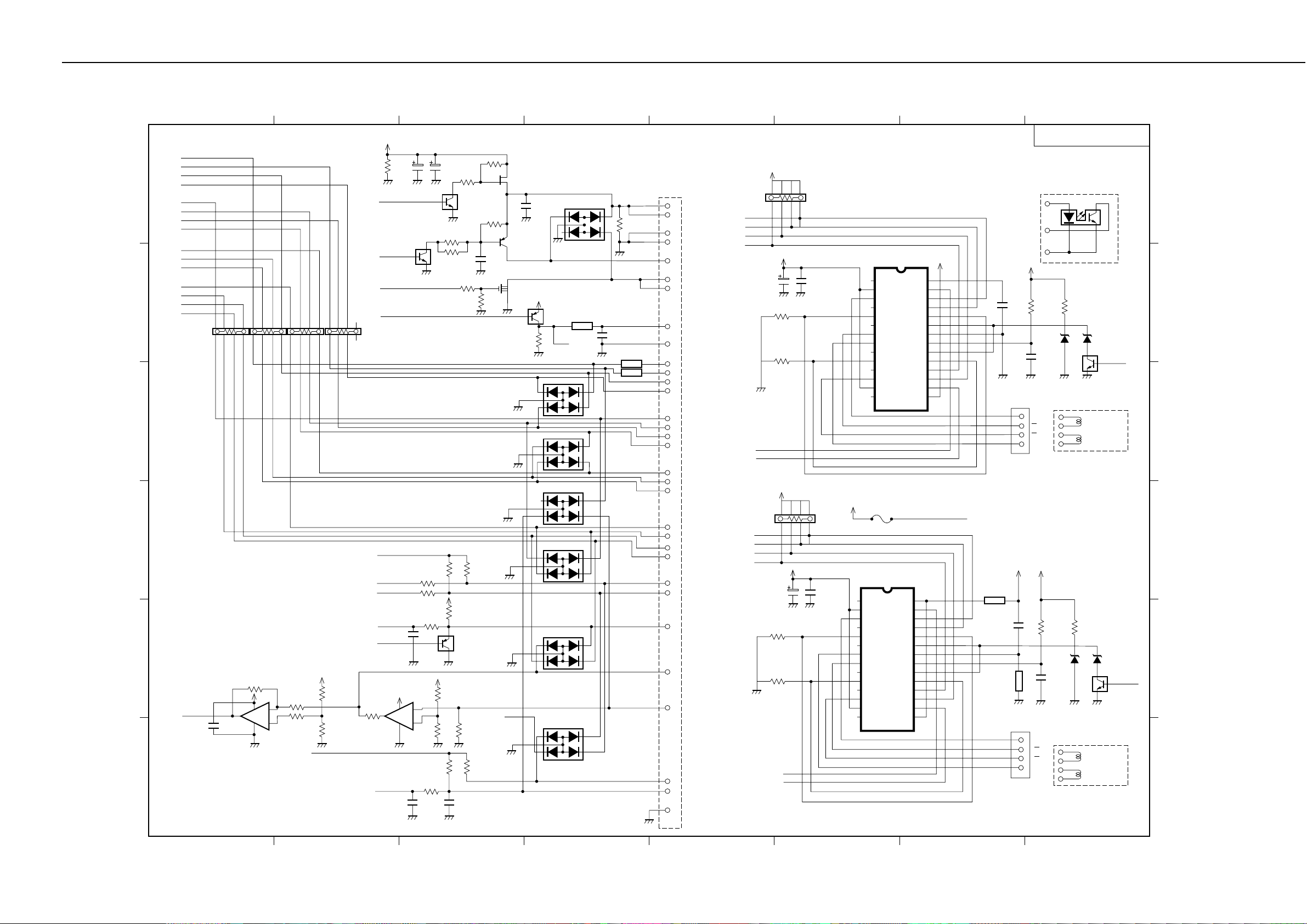
HELN325-3(32P)
J5
5
HVH
6
HVH
1
VHG
2
VHG
7
W-HT
3
HT0
4
HT1
HVdd
23
HVss
14
HCLOCK
24
HDATA
28
HLATCH
25
HRES
26
HENB0
15
HENB1
17
HENB2
27
HENB3
18
20
BENB1
21
BENB2
BENB3
22
OddENB
19
16
EvenENB
11
ID0
12
ID1
8
INKS1
INKS2
13
TOP
9
10
DIODEA
DIODEK
29
32
HPA
30
HPO
31
HPG
10K,1/8W
<01-E8>
<01-D8>
<01-D8>
<01-D8>
<01-D8>
<01-D8>
<01-A8>
<01-A8>
<01-A8>
<01-A8>
RA4
CR10A
CR11A
CR10B
CR11B
C205
100µ,35W
CRA
CRB
RA3
10K,1/8W
LF10A
LF11A
LF10B
LF11B
C202
100µ,35W
0.51,1/4W
0.51,1/4W
<01-A8>
<01-A8>
+5V
8
3
VM
0.51,1/4W
R74
0.51,1/4W
R75
+5V
R70
R71
LFA
LFB
VM
567
124
0.1µ,50W
5
678
4
312
C206
VM-G
C203
0.1µ,50W
VM-G
1
2
3
4
5
6
7
8
9
10
11
12
13
14
R12P
MTD2007F
1
NC
2
VssA
3
Out1
4
NC
5
RsA
6
NC
7
Out2
8
Out3
9
NC
10
RsB
11
NC
12
Out4
13
VssB
14
NC
IC12
MTD2007F
NC
VssA
Out1
NC
RsA
NC
Out2
Out3
NC
RsB
NC
Out4
VssB
NC
FU1
IC13
Vcc
INA
IOA
IIA
VsA
VrefA
LG
C/R
VrefB
VsB
IIB
IOB
INB
Vcc
Vcc
INA
IOA
VsA
VrefA
C/R
VrefB
VsB
IOB
INB
Vcc
LOGIC BOARD 03
Home Psition
Sensor
HPA
HPO
C62
0.1µ,25W
J3
HPG
+5V
02DZ3.0Z
C63
1
A
2
A
3
B
4
B
R76
10K,1/16W
ZD20
4700p,50V
R77
360,1/10W
02DZ2.0Z
ZD21
2
CRVREF
3
1
Q14
FA1L4M
Approx.6 Ω/
phase
<01-D8>
+5V
28
27
26
25
IIA
24
23
22
LG
21
20
19
18
IIB
17
16
15
VH
F
F
D
C
+5V
+5V
28
27
26
25
24
23
22
21
20
19
18
17
16
15
N1608Z300T01
FB102
N1608Z300T01
FB101
J4
1
2
3
4
C60
C61
A
A
B
B
0.1µ,25W
02DZ3.0Z
R72
R73
10K,1/16W
ZD18
4700p,50V
Paper Feed
Motor
Approx.6 Ω/
360,1/10W
02DZ2.0Z
ZD19
2
1
Q13
FA1L4M
phase
LFVREF
3
<01-D7>
B
A
5-37
 Loading...