

Canon CLBR 460ps, CLBP-460PS Service Manual

SERVICE
MANUAL
REVISION 0
OCT. 1998
COPYRIGHT © 1998 CANON INC. CANON CLBP-460PS REVISION 0 OCT. 1998 PRINTED IN JAPAN (IMPRIME AU JAPON)
RY8-1389-000

COPYRIGHT © 1998 CANON INC
Printed in Japan
Imprimé au Japon
Prepared by
PERIPHERAL PRODUCTS QUALITY PLANNING DIV.
PERIPHERAL PRODUCTS TECHNICAL DOCUMENTATION DEPT.
CANON INC.
5-1, Hakusan 7-chome, Toride-City, Ibaraki-Pref. 302-8501, Japan
Use of this manual should be
strictly supervised to avoid
disclosure of confidential
information.

PREFACE
This Service Manual contains basic information required for after-sales service of the laser
beam printer (hereinafter referred to as the “printer”) CLBP-460PS. This information is vital to
the service technician in maintaining the high print quality and performance of the printer.
The paper feeder and duplexing unit, which are prepared for the printer as options, are also
described in this manual.
This manual consists of the following chapters:
Chapter 1: Product information
Features, specifications, operation, and installation
Chapter 2: Operation and Timing
A description of the operating principles and timing sequences of the electrical
and mechanical systems.
Chapter 3: The Mechanical System
Explanation of mechanical operation, disassembly, reassembly, and adjustment
procedures
Chapter 4: Troubleshooting
Maintenance and servicing, reference values and adjustments, troubleshooting
procedures, lubricants, and solvents
Appendix: General timing chart, general circuit diagram, etc.
Information in this manual is subject to change as the product is improved or redesigned.
All relevant information in such cases will be supplied in Service Information Bulletins.
A thorough understanding of this printer, based on information in this Manual and Service
Information Bulletins, is required for maintaining its performance and for locating and repairing the causes of malfunctions.

DTP system
This manual was produced on an Apple PowerMacintosh 9500/200 personal computer and output by an Apple LaserWriter 16/600 PS laser beam printer.
All graphics were produced with Macromedia FreeHand (J), and all documents and page lay-
outs were created with QuarkXPress (E).
The video images were captured with SONY digital video camcorder and MASS microsystems
Quickimage 24 video capture board, and modified with Adobe Photoshop™ (J).

CONTENTS
CHAPTER 1 PRODUCT INFORMATION
I. FEATURES .............................1-1
II. SPECIFICATIONS....................1-3
A. Printer...............................1-3
B. Video Controller ................ 1-5
III. SAFETY INFORMATION .....1-8
A. Laser Safety ...................... 1-8
B. Toner Safety......................1-8
C. Ozone Safety .....................1-8
D. Power Supply Safety..........1-8
IV. PARTS OF THE PRINTER .......1-9
A. External View ....................1-9
B. Cross Sectional View .........1-11
V. INSTALLATION .......................1-13
A. Notes................................. 1-13
B. Choosing a Location..........1-13
C. Unpacking and Installation
.........................................1-15
D. Storing and Handling
Cartridges and ITB Unit.....1-23
VI. MAINTENANCE AND SERVICING BY
THE CUSTOMER ....................1-26
VII. OPERATION............................1-28
A. Control Panel .................... 1-28
B. Control Panel Menu...........1-30
CHAPTER 2 OPERATION AND TIMING
I. BASIC OPERATION.................2-1
A. Functions..........................2-1
B. Basic Sequence of
Operations.........................2-2
C. Power-on Sequence............2-3
II. ENGINE CONTROL SYSTEM....2-4
A. DC Controller PCB.............2-4
B. Fixing Control Circuit ....... 2-14
C. High-voltage Power Supply
Circuit...............................2-20
D. Low-voltage Power Supply
Circuit...............................2-25
E. Video Interface Control .....2-28
F. Other Control....................2-30
III. LASER/SCANNER SYSTEM..... 2-37
A. Laser System.....................2-37
B. Laser Control Circuit.........2-39
C. Scanner System ................2-42
IV. IMAGE FORMATION SYSTEM .2-44
A. Outline..............................2-44
B. Operation .......................... 2-45
C. Print Process.....................2-62
D. Image Stabilization Control
.........................................2-73
V. PICK-UP/FEED SYSTEM.........2-75
A. Outline..............................2-75
B. Paper Pick-up ....................2-77
C. Feed Unit ..........................2-84
D. Fixing and Delivery Unit....2-85
E. Paper Jam Detection .........2-89
VI. VIDEO CONTROL SYSTEM......2-90
A. Video Controller PCB......... 2-90
B. Control Panel .................... 2-93
C. Self Test............................2-94
D. Boot ROM Menu ................2-96
E. Powar Saver.......................2-98
VII. DUPLEXING UNIT ...................2-99
A. Outline..............................2-99
B. Reversing and Duplex
Pick-up Operation .............2-101
C. Paper Jam Detection.........2-106
VIII.PAPER FEEDER......................2-108
A. Outline..............................2-108
B. Pick-up and
Feed Operation.................. 2-109
C. Paper Jam Detection.........2-110

CHAPTER 3 THE MECHANICAL SYSTEM
I. INTRODUCTION......................3-1
A. Outline .............................3-1
B. Removal of the
Toner Cartridge
whit Manual Operation ......3-2
II. EXTERNALS ........................... 3-4
A. Locations ..........................3-4
B. External Covers.................3-5
C. Control Panel ....................3-9
III. MAIN UNITS...........................3-10
A. Laser/Scanner Unit ...........3-10
B. Drum Drive Unit................3-11
C. Rotary Drive Unit..............3-14
D. Multi-purpose
Pick-up Unit ......................3-14
E. Feed Unit .......................... 3-16
F. Fixing Unit ........................3-16
G. Delivery Unit.....................3-17
H. Drum Cartridge
Drawer Unit.......................3-17
I. ITB Unit Drawer Unit.........3-18
J. Developing Rotary.............3-19
IV. MAIN PARTS ..........................3-21
A. Cassette Pick-up Roller ..... 3-21
B. Cassette Feed Roller..........3-21
C. Cassette Separation Roller
.........................................3-21
D. Multi-purpose Tray
Pick-up Roller ...................3-22
E. Separation Pad ..................3-22
F. Secondary Transfer Roller
.........................................3-24
G. Upper Thermoswitch .........3-24
H. Lower Thermoswitch ......... 3-25
I. Upper Thermistor..............3-25
J. Lower Thermistor..............3-26
K. Upper Fixing Heater ..........3-26
L. Lower Fixing Heater ..........3-27
M. Upper Fixing Roller ...........3-28
N. Lower Fixing Roller ...........3-30
O. 90-Fan/60-Fan Air Filter ... 3-32
P. 40-Fan Air Filter ...............3-32
V. SWITCHES/SENSORS.............3-33
A. Locations ..........................3-33
B. ITB Unit Drawer Open
Detection Switch...............3-35
C. Toner Cartridge Door Open
Detection Switch...............3-35
D. Drum Cartridge Drawer Open
Detection Switch...............3-36
E. +24V Interruption Switch1
.........................................3-36
F. +24V Interruption Switch2
.........................................3-37
G. Cassette Paper Size
Detection Switch...............3-37
H. Power Switch.....................3-38
I. Test Print Switch ..............3-38
J. Registration Paper Sensor .3-39
K. Multi-purpose Tray
Last Paper Sensor.............3-39
L. Multi-Purpose Tray
Paper Sensor .....................3-40
M. ITB Home
Position Sensor .................3-40
N. Fixing Unit Pressure
Release Sensor ..................3-41
O. Paper Delivery Sensor .......3-41
P. Cassette Paper Sensor .......3-42
Q. Face-down Tray
Paper Full Sensor ..............3-42
R. Developing Rotary
Home Position Sensor .......3-43
S. Toner Cartridge
Contact Sensor.................. 3-43
T. Toner Level Sensor............3-44

U. Waste Toner Full Sensor....3-44
V. OHT Sensor .......................3-45
W. Density Sensor ..................3-45
VI. SOLENOIDS/CLUTCHES .........3-47
A. Locations ..........................3-47
B. Multi-purpose Tray
Pick-up Solenoid ...............3-48
C. Cassette
Pick-up Solenoid ...............3-48
D. Registration Roller Clutch.3-49
E. ITB Unit Contact Clutch....3-49
F. ITB Cleaning Roller
Press Clutch ......................3-50
G. Secondary Transfer Roller
Press Clutch ......................3-50
VII. MOTORS/FANS ......................3-51
A. Locations ..........................3-51
B. Fixing Motor Unit..............3-52
C. Pick-up Motor.................... 3-52
D. Developing Rotary Motor...3-53
E. Drum Motor.......................3-53
F. Toner Cartridge
Motor Unit ........................3-54
G. 90-Fan............................... 3-54
H. 60-Fan...............................3-55
I. 40-Fan...............................3-56
VIII.ELECTRONIC COMPONENTS ..3-58
A. Locations ..........................3-58
B. DC Controller PCB.............3-59
C. Connector PCB ..................3-60
D. Low-voltage Power
Supply Unit .......................3-60
E. High-voltage
Power Supply Unit.............3-61
F. Developing PCB .................3-61
G. Feed PCB...........................3-62
H. Multi-purpose Tray PCB.....3-62
I. Toner Level
Detection PCBs
[Emitter and Receiver].......3-64
J. Waste Toner Full
Detection PCBs
[Emitter and Receiver].......3-64
K. Cassette Paper Size
Detection PCB ...................3-65
L. Video Controller PCB......... 3-65
IX. DUPLEXING UNIT...................3-66
A. External Covers.................3-66
B. Motors/Solenoids ..............3-69
C. Sensors .............................3-72
D. Electrovic Components .....3-75
X. PAPER FEEDER......................3-77
A. Locations ..........................3-77
CHAPTER 4 TROUBLESHOOTING
I. PREFACE ...............................4-1
A. Malfunction Diagnosis
Flowchart .......................... 4-1
B. Initial Check ..................... 4-4
C. Test Print .......................... 4-6
II. IMAGE DEFECT...................... 4-17
III. PAPER JAMS
TROUBLESHOOTING ..............4-27
IV. PAPER TRANSPORT
TROUBLESHOOTING ..............4-34
V. MALFUNCTION
TROUBLESHOOTING ..............4-36
VI. MALFUNCTION STATUS
TROUBLESHOOTING ..............4-37
VII. MEASUREMENT AND
ADJUSTMENT ........................4-53
A. Mechanical Adjustment ..... 4-53
B. Electrical Adjustment........ 4-54
C. Variable Resistors [VR],
Test Print, Jumpers,
and Switches on PCBs .......4-55

APPENDIX
I. GENERAL TIMING CHART ......A-1
II. GENERAL CIRCUIT DIAGRAM
.........................................A-25
III. LIST OF SIGNALS................... A-29
IV. MESSAGE TABLE ...................A-36
VIII.MAINTENANCE AND
SERVICING.............................4-59
A. Periodic Replacement Parts
.........................................4-59
B. Expected Service Life of
Consumable Parts.............. 4-59
C. Periodic Service ................4-60
D. Cleaning During a Sarvice Visit
.........................................4-60
E. Standard Tools ..................4-64
F. Special Tools.....................4-65
G. List of Lubricants and
Cleaners ............................4-66
IX. SERVICE MODE .....................4-67
A. Outline..............................4-67
B. Mode Description ..............4-73
X. LOCATION OF CONNECTORS .4-78

CHAPTER 1
PRODUCT INFORMATION
I. FEATURES ............................. 1-1
II. SPECIFICATIONS.................... 1-3
III. SAFETY INFORMATION...... 1-8
IV. PARTS OF THE PRINTER ....... 1-9
V. INSTALLATION ....................... 1-13
VI. MAINTENANCE AND
SERVICING BY THE
CUSTOMER ............................ 1-26
VII. OPERATION............................ 1-28


I. FEATURES
1. The smallest and lightest color printer
This printer is the smallest and lightest printer among the Canon color laser beam printers.
2. High resolution and high speed printing
The printer features continuous tone 256-level grayscale/color output at 600 x 600 dpi with
the standard memory configuration of 32MB.
The printer is capable of printing 4 ppm (page per minute) in full color mode and 16 ppm in
mono-color mode (A4 or Letter size).
3. Intermediate transfer belt (ITB)
The printer utilizes an intermediate transfer belt, which forms the toner image by accumulating the four color images required for each full-color print and transferring this image to the
paper. The ITB makes the paper path from the registration area to the fixing area straight,
enabling color printing of various paper types and reducing the likelihood of paper jams.
4. Oilless fixing unit
The printer utilizes toner which contains wax, reducing the likelihood of toner adhesion to the
fixing roller surface and allowing the fixing unit to be oilless.
5. Easy maintenance
The main parts in the printer are structured to simplify maintenance of the printer. The main
parts are as follows.
• ITB unit
• Toner cartridge (Bk, M, C, Y)
• Drum cartridge (photosensitive drum and waist toner case)
• Fixing unit (Fixing unit is not fixed with screws and can be replaced simply by shifting the
• fixing levers.)
• Feed roller, separation roller, and secondary transfer roller
6. Flexible paper handling
The universal cassette (250 sheets of 80g/m2paper) and multi-purpose tray (100 sheets of
80g/m2paper) allow the printer to handle various paper types such as plain paper, OHT, labels,
postcards and envelopes.
With an optional paper feeder (500 sheets of 80g/m2paper) installed in the printer, three way
paper pick-up and large volume printing are made possible.
7. Duplex printing
With an optional duplexing unit installed in the printer, automatic color duplex printing is
made possible.
8. Wide networking
By using the standard equipped Ethernet or optional TokenRing, the printer can support the
following network protocols.
• TCP/IP
• Apple Talk (Ethernet)
• IPX (Novell)
• SMB (Server Message Block)
1 - 1
CHAPTER 1

9. Automatic PDL switching
The printer supports Hewlett-Packard PCL 5C and Adobe PostScript 3TM. The printer can
automatically switch PDL between PCL and PostScript according to the received data.
1 - 2
CHAPTER 1

II. SPECIFICATIONS
A. Printer
1. Printer engine
1) Type Desktop page printer
2) Printing method Electrophotography
3) Printing speed (Note 1) About 4 pages/min (A4, full color)
About 16 pages/min (A4, mono-color)
4) First print time (Note 2) 37 seconds or less (A4, full color)
26 seconds or less (A4, mono-color)
5) Wait time (Note 3) 250 seconds or less
6) Resolution
Horizontal 600 dpi
Vertical 600 dpi
7) Image formation system
Laser Semiconductor laser
Scanning system Rotating six-faced prism mirror
Photosensitive medium OPC
Charging Roller charging
Exposure Laser scanning
Toner Non-magnetic single-component dry toner (Y/M/C), magnetic sin-
gle-component dry toner (Bk)
Development Toner projection development
Toner supply Replaceable Bk toner cartridge
The Bk toner cartridge can print about 9,000 A4- or Letter-size
sheets (if the average print coverage is a 4% image dot ratio with
the print density setting at midpoint.)
Replaceable Y, M, and C toner cartridges
The Y, M, and C toner cartridge can print about 6,000 A4- or
Letter-size sheets (if the average print coverage is a 4% image dot
ratio with the print density setting at midpoint.)
Transfer Primary transfer: Intermediate transfer belt
Secondary transfer: Secondary transfer roller
Separation Curvature
Cleaning The photosensitive drum is cleaned with a rubber blade, and the
intermediate transfer belt is cleaned with the ITB cleaning roller.
Fixing method Heated rollers (Upper heater: 490 W (127 V), 450 W (240 V))
(Lower heater: 490 W (127 V), 450 W (240 V))
8) Paper pick-up Multi-purpose tray
Cassette
Paper feeder (option)
Paper types Plain paper, labels, OHT (recommended by Canon) (Note 4),
envelopes, postcards
Paper size
Multi-purpose tray Plain paper (60-135 g/m
2
Canon recommended paper) from 76.2
mm (width) x 127 mm (length) (minimum) to 216mm (width) x 356
mm (length) (maximum), COM10, Monarch, B5, C5, DL size
envelopes, and papers shown above
Cassette Letter, Legal, Executive, A4, B5, A5 size plain paper (60-105 g/m
2
Canon recommended paper)
1 - 3
CHAPTER 1

Multi-purpose tray capacity
Plain paper:
15 mm stack (About 100 sheets of 75g/m2paper can be stacked.)
Envelope:
12 mm stack (About 15 to 20 COM10 size envelopes can be
stacked.)
Cassette capacity 25 mm stack (About 250 sheets of 75g/m2paper can be stacked.)
Cassette type
Cassette Universal (Can adapt to Letter, Legal, Executive, A4, or A5 size)
9) Paper delivery Face-down/face-up
Face-down tray capacity About 200 sheets of 75g/m2paper
Face-up tray capacity About 50 sheets of 75g/m2paper
10) Duplex printing
Automatic duplex printing
Only plain paper (60-105 g/m2Canon recommended paper) can be
printed on both sides automatically when the duplexing unit
(option) is installed.
Manual duplex printing Not to be used.
11) Operating environment See Fig. 1-5-1 in Section V, Installation.
12) Maximum power consumption
About 1100 W or less (100-127 V, room temperature of 20°C)
About 1100 W or less (220-240 V, room temperature of 20°C)
13) Noise level (Declared noise emissions in accordance with ISO 9296)
Sound power level (1B = 10 dB) 6.8B or less (printing)
5.8B or less (standby)
Sound pressure level 53 dB or less (printing)
(Bystander position) 43 dB or less (standby)
14) Dimensions 500 (width) x 559 (depth) x 394 (height) mm
15) Weight About 48.0 kg (printer-including cassette)
About 1.4 kg (drum cartridge)
About 0.92 kg (Bk toner cartridge)
About 0.77 kg (Y, M, and C toner cartridges)
About 2.0 kg (ITB unit)
16) Power supply 100-127 V (50/60 Hz)
220-240 V (50/60 Hz)
(Voltage tolerance ±10% or less)
17) Options Duplexing unit and paper feeder
Notes: 1. Test print when the rated power supply voltage is input at a room temperature of
20°C
2. Time after the printer receives a PRINT signal from the video controller when it is
ready at an ambient temperature of 20°C until it ends printing and delivering an A4size paper onto the face-down tray.
3. Time from power-ON until the printer completes WAIT period at ambient temperature
of 20°C and the rated AC power source voltage.
4. OHT (OHT T-H1) for CLBP-360PS cannot be used on this printer. As T-H1 is
extremely thin and contains oil, it may cause roller wrapping jams in the fixing unit
if it is used on this printer which utilizes two fixing heaters and produces large
amount of heat.
1 - 4
CHAPTER 1

B. Video Controller
1) CPU 32-bit RISC processor: MIPS R4300 (133MHz)
2) RAM Standard 32MB
Maximum 192MB
3) ROM Flash ROM: 16MB (PCL/PostScript)
4) ROM /RAM DIMM slot 4 (ROM:1, RAM:3)
5) Host interface Standard: IEEE 1284 parallel interface, Ethernet (10/100Base-T,
AUI)
Option: Expansion interface (Token Ring)
6) PDL Standard: PCL 5C, Adobe PostScript Level 3
7) Option HDD HD83 (2.1GB)
8) Resident fonts
PCL fonts: 45 (44 Scalable fonts, 1 Bitmap font)
1 - 5
CHAPTER 1
Albertus Medium (27), Albertus Extra Bold (28), Antique
Olive (19), Antique Olive-Bold (20), Antique Olive-Italic (21),
Arial (29), Arial-Bold (30), Arial-Italic (31), Arial-BoldItalic
(32), CG Omega (5), CG Omega-Bold (6), CG Omega-Italic
(7), CG Omega-BoldItalic (8), CG Times (1), CG Times-Bold
(2), CG Times-Italic (3), CG Times-BoldItalic (4), Clarendon
Condensed (10), Coronet (9), Courier (0), Courier-Bold (39),
Courier-Italic (40), Courier-BoldItalic (41), Garamond
Antiqua (22), Garamond Halbfett (23), Garamond Kursiv
(24), Garamond Kursiv Halbfett (25), Letter Gothic (42),
Letter Gothic-Bold (43), Letter Gothic-Italic (44), Line
Printer (45)Note, Marigold (26), Symbol (37), Times New
(33), Times New-Bold (34), Times New-Italic (35), Times
New-BoldItalic (36), Univers Medium (11), Univers Bold
(12), Univers Italic (13), Univers BoldItalic (14), Univers
Medium Condensed (15), Univers Bold Condensed (16),
Univers Medium Condensed Italic (17), Univers Bold
Condensed Italic (18), Wingdings (38)
Scalable
Pitch
(CPI)
Size
(Points)
Remarks
It is possible to
print both portrait
and landscape orientations.
Type face

PostScript fonts: 136 (117 Adobe Type 1 fonts, 19 Truetype fonts)
1 - 6
CHAPTER 1
Type face
• Adobe Type 1 PostScript fonts
AlbertusMT, AlbertusMT-Italic, AlbertusMT -Light,
AntiqueOlive-Roman, AntiqueOlive-Bold, AntiqueOliveCompact, AntiqueOlive-Italic, AvantGarde-Book,
AvantGarde-BookOblique, AvantGarde-Demi, AvantGardeDemiOblique, Bodoni, Bodoni-Bold, Bodoni-Italic, BodoniBoldItalic, Bodoni-Poster, Bodoni-PosterCompressed,
Bookman-Demi, Bookman-DemiItalic, Bookman-Light,
Bookman-LightItalic, Carta, Clarendon, Clarendon-Bold,
Clarendon-Light, CooperBlack, CooperBlack-Italic,
Copperplate-ThirtyThreeBC, Copperplate-ThirtyTwoBC,
Coronet, Courier, Courier-Bold, Courier-Oblique, CourierBoldOblique, Eurostile, Eurostile-Bold, EurostileExtendedTow, Eurostile-BoldExtendedTow, GillSans,
GillSans-Bold, GillSans-Italic, GillSans-BoldItalic, GillSansCondensed, GillSans-BoldCondensed, GillSans-Light,
GillSans-LightItalic, GillSans-ExtraBold, Goudy, GoudyBold, Goudy-Italic, Goudy-BoldItalic, Goudy-ExtraBold,
Helvetica, Helvetica-Bold, Helvetica-BoldOblique, HelveticaCondensed, Helvetica-Condensed-Bold, HelveticaCondensed-BoldObl, Helvetica-Condensed-Oblique,
Helvetica-Narrow, Helvetica-Narrow-Bold, Helvetica-NarrowBoldOblique, Helvetica-Narrow-Oblique, Helvetica-Oblique,
JoannaMT, JoannaMT-Bold, JoannaMT -Italic, JoannaMTBoldItalic, LetterGothic, LetterGothic-Bold, LetterGothicBoldSlanted, LetterGothic-Slanted, LubalinGraph-Book,
LubalinGraph-BookOblique, LubalinGraph-Demi,
LubalinGraph-DemiOblique, Marigold, MonaLisa-Recut,
NewCenturySchlbk-Roman, NewCenturySchlbk-Bold,
NewCenturySchlbk-Italic, NewCenturySchlbk-BoldItalic,
Optima, Optima-Bold, Optima-Italic, Optima-BoldItalic,
Oxford, Palatino-Roman, Palatino-Bold,
Palatino-Italic, Palatino-BoldItalic, StempelGaramondRoman, StempelGaramond-Bold, StempelGaramond-Italic,
StempelGaramond-BoldItalic, Symbol, Tekton, TimesRoman, Times-Bold, Times-Italic, Times-BoldItalic, Univers,
Univers-Bold, Univers-BoldExt, Univers-BoldExtObl,
Univers-BoldOblique, Univers-Condensed, UniversCondensedBold, Univers-CondensedBoldOblique, UniversCondensedOblique, Univers-Extended, UniversExtendedObl, Univers-Lighit, Univers-LighitOblique,
Univers-Oblique, ZapfChancery-MediumItalic,
ZapfDingbats.
• TrueType fonts
Apple-Chancery, ArialMT, Arial-BoldMT, Arial-ItalicMT,
Arial-BoldItalicMT, Chicago, Geneva, HoeflerText-Regular,
HoeflerText-Black, HoeflerText-Italic, HoeflerTextBlackItalic, HoeflerText-Ornaments, Monaco, NewYork,
TimesNweRomanPSMT, TimesNweRomanPS-BoldMT,
TimesNweRomanPS-ItalicMT, TimesNweRomanPSBoldItalicMT, Wingdings-Regular.
Scalable
Pitch
(CPI)
Size
(Points)
Remarks
It is possible to
print both portrait
and landscape orientations.

C. Options
1. Duplexing unit
1) Pick-up speed About 4 images (2 sheets) /min.(A4, full color)
About 10 images (5 sheets) /min.(A4, mono-color)
2) Paper types Letter, Legal, Executive, A4, B5 size plain paper (60-105 g/m
2
Canon recommended paper)
3) Dimensions 500 (width) x 708 (depth) x 218 (height) mm
4) Weight About 13.0 kg
5) Power supply 100-127 V (50/60 Hz)
220-240 V (50/60 Hz)
(Voltage tolerance ±10% or less)
DC5V (supplied from the printer)
2. Paper feeder
1) Pick-up speed About 4 pages/min.(A4, full color)
About 16 pages/min (A4, mono-color)
2) Paper types Letter, Legal, Executive, A4, B5, A5 size plain paper (60-105 g/m
2
Canon recommended paper)
3) Dimensions 500 (width) x 559 (depth) x 125 (height) mm
4) Weight About 10.0 kg
5) Power supply DC24V (supplied from the printer)
DC5V (supplied from the printer)
Specifications are subject to change with product improvement.
1 - 7
CHAPTER 1
III. SAFETY INFORMATION
A. Laser Safety
The laser/scanner unit emits invisible laser beam. DO NOT disassemble the unit as the laser
beam, can possibly damage your eyes. The unit cannot be adjusted in the field. The following
label is attached to the cover of the unit:
Fig. 1-3-1
B. Toner Safety
Toner is a harmless substance composed of plastics and a pigment.
If you get toner on your skin or clothes, remove as much as possible with dry tissue and then
wash it with cold water.
If you wash in hot water, the toner gels and becomes hard to remove.
As toner easily decomposes vinyl material, do not let it come into contact with this material.
C. Ozone Safety
An infinitesimal amount of ozone gas (O3) is generated during corona discharge from the charging roller used in this printer. The ozone gas is emitted only when the printer is operating.
The printer meets the ozone emission standard decided by the Underwriters Laboratory (UL)
when it is shipped from the factory.
D. Power Supply Safety
Note that even if the power switch is turned OFF, the current still flows to the primary side of
the power supply unit of the printer.
Unplug the power cable before disassembling and reassembling the printer.
1 - 8
CHAPTER 1
ATTENTION
VORSICHT
ATTENZIONE
PRECAUCION
VARO!
VARNING!
ADVARSEL!
ADVARSE
L
UNSICHTBARE LASERSTRAHLUNG. WENN ABDECKUNG GEOFFNET.
NICHT DEM STRAHL AUSSETZEN.
RAYONNEMENT LASER INVISIBLE EN CAS D'O UVERTURE.
EXPOSITION DANGEREUSE AU FAISCEAU.
INVISIBLE LASER RADIATION WHEN OPEN.
AVOID EXPOSURE TO BEAM.
Invisible laser radiation when open.
AVOID DIRECT EXPOSURE TO BEAM.
RADIAZIONE LASER INVISIOILE IN CASO DI APERTURA.
EVITARE L'ESPOSIZIONE AL FASCIO.
RADIACION LASER INVISIBLE CUANDO SE ABRE.
EVITAR EXPONERSE AL RAYO.
AVATTAESSA OLET ALTTIINA NAKYMATTOMALLE
LASERSATEILYLLE. ALA KATSO SATEESEEN.
OSYNLIG LASERSTRALNING NAR DENNA DEL AR OPPNAD.
BETRAKTA EJ STRALEN.
USYNLIG LASER STRALING. NAR DENNE ER ABEN.
UNDGA BESTRALING.
USYNLIG LASERSTRALING NAR DEKSEL APNES.
UNNGA EKSPONERING FOR
STRALEN.
DANGER
CAUTION
IV. PARTS OF THE PRINTER
A. External View
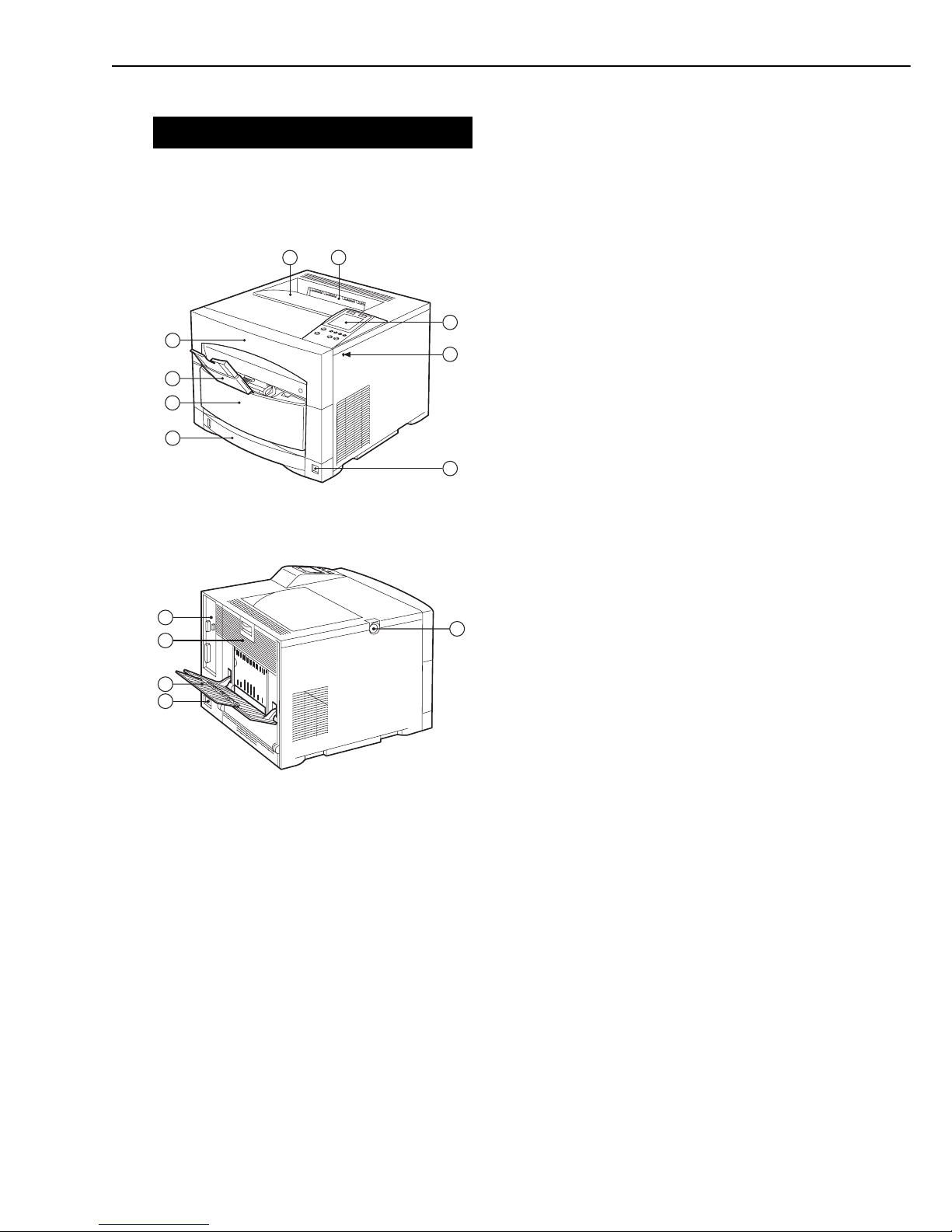
1. External view of the printer
Fig. 1-4-1
Fig. 1-4-2
1: Top cover
2: Face-down delivery slot
3: Control panel
4: Test print switch
5: Power switch
6: Universal cassette
7: ITB unit drawer
8: Multi-purpose tray
9: Drum cartridge drawer
10: Top cover unlock button
11: Power receptacle
12: Face-up tray
13: Rear cover
14: Video controller unit
1 - 9
CHAPTER 1
14
13
11
12
10
1
4
2
3
5
6
7
8
9
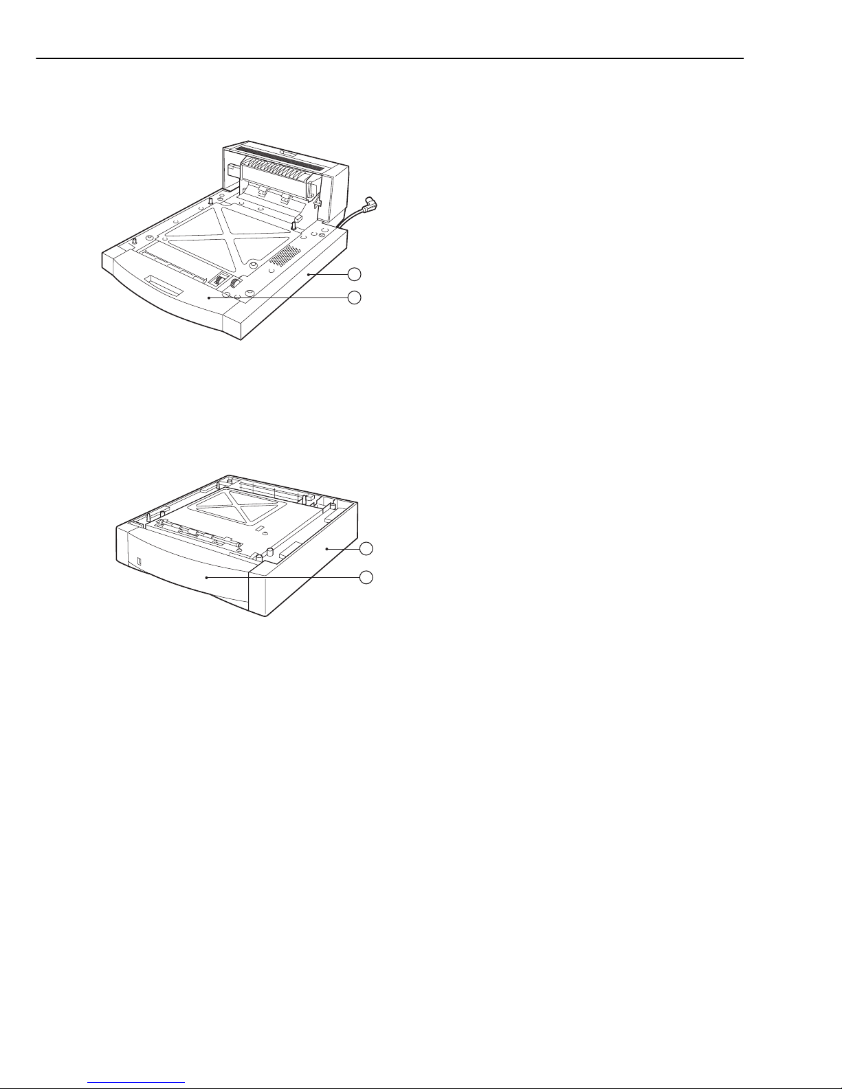
2. External view of the duplexing unit
Fig. 1-4-3
3. External view of the paper feeder
Fig. 1-4-4
15: Duplexing unit
16: Duplex feed unit
17: Paper feeder
18: Paper cassette
1 - 10
CHAPTER 1
15
16
18
17

B. Cross Sectional View
1. Cross sectional view of the printer
Fig. 1-4-5
1 - 11
CHAPTER 1
3 5
1
2
4
6
8
9
11
10
12
13
14
15
16
1819
21
22
23
24
7
17
20
1: Photosensitive drum
2: Primary charging roller
3: Density sensor
4: Laser/scanner unit
5: Drum cartridge
6: Primary transfer roller
7: ITB unit
8: Multi-purpose tray
9: Multi-purpose tray paper pick-up roller
10: Registration roller
11: Feed roller
12: Cassette feed roller
13: Cassette paper pick-up roller
14: Secondary transfer roller
15: ITB cleaning roller
16: Cassette
17: Feed belt unit
18: Upper fixing roller
19: Lower fixing roller
20: Fixing delivery roller
21: Face-up deflector
22: Developing rotary
23: Toner cartridge
24: Face-down delivery roller
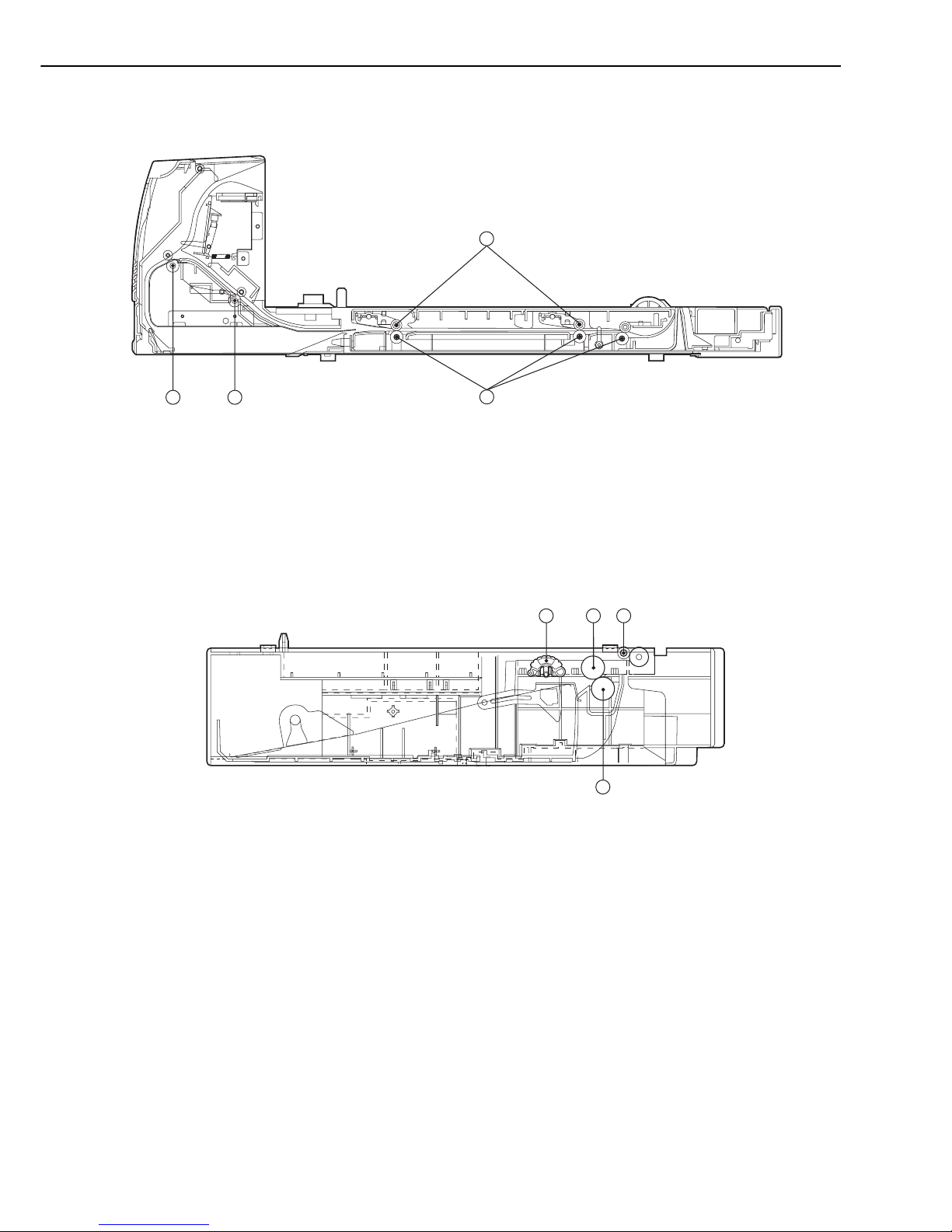
2. Cross sectional view of the duplexing unit
Fig. 1-4-6
3. Cross sectional view of the paper feeder
Fig. 1-4-7
1 - 12
CHAPTER 1
1: Pick-up roller
2: Feed roller 1
3: Feed roller 2
4: Separation roller
1
2
2
3
1 2
3
4
1: Pressure roller
2: Duplex feed roller
3: Reversing roller
V. INSTALLATION
A. Notes
This printer was carefully adjusted and strictly inspected before being packed.
To ensure that it performs as intended, it is very important to install the printer correctly.
The service engineer should have a complete knowledge of the printer, choose a good location,
install the printer according to the proper procedure, and check it out before it is used.
B. Choosing a Location
The following requirements must be met when installing the printer.
The service engineer should inspect the customer’s premises before installing the printer.
1. Power supply
The power supply should meet the following requirements:
• Line voltage (AC): Within ±10% of rated voltage
• Line frequency: Rated frequency
• Grounding: Grounding that meets the safety standard.
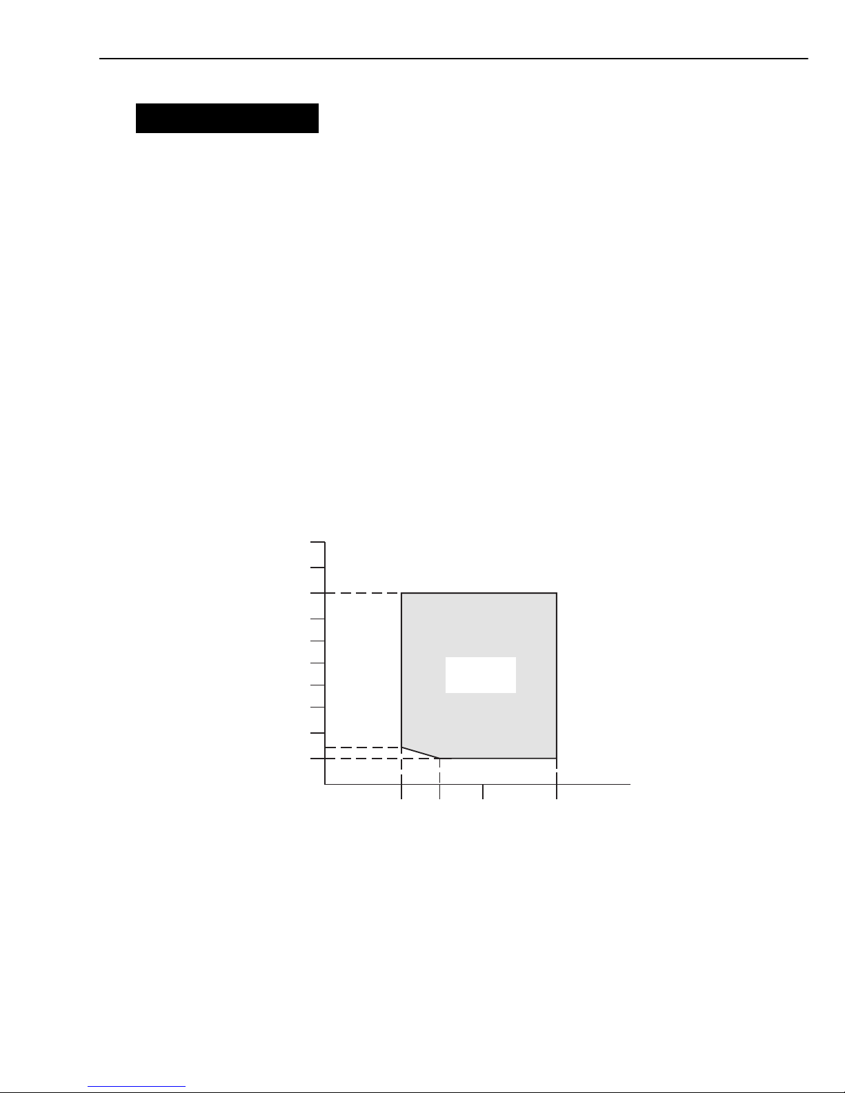
2. Operating conditions
The location should meet the following requirements.
• The printer should be placed on a flat and level surface.
• The temperature and humidity should be within the range shown below.
• The location should be well ventilated.
Fig. 1-5-1
1 - 13
CHAPTER 1
0
30
100
20
40
60
80
0
2010
10
15
14
Humidity (%RH)
Temperature
(˚C)
Operating
environment
Do not install the printer in these places:
• Areas exposed to direct sunlight
If unavoidable, hang heavy curtains to shut out the direct sunlight.
• Areas exposed to the direct wind from the air-conditioning duct.
• Near magnets or equipment that produces a magnetic field
• Areas with vibration
• Dusty areas
• Near flames or water
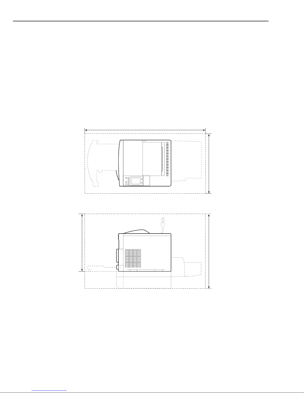
3. Installation space
There must be enough space around the printer to operate it. (See Figure 1-5-2.)
If the printer is to be placed on a desk, be sure that the desk is large enough to accommodate
its feet (rubber pads) and sturdy enough to carry its weight (about 48 kg).
Fig. 1-5-2
1 - 14
CHAPTER 1
820mm
700mm
1560mm
Cassette
Paper feeder
(Option)
538mm
Duplexing unit
(Option)
Duplexing unit
(Option)
C. Unpacking and Installation
If the boxed printer is brought into a warm place from a cold place, condensation will form on
the printer surfaces. This will cause various problems, such as print defects. To stop this happening, leave the printer in its box to acclimatize it to room temperature before unpacking it.
This will take at least an hour.
1. Unpacking
1) Open the packaging.
2) Take out the accessories. Confirm that the power cord (100 to 127V), toner cartridges (total:
4), and drum cartridge are included.
Confirm that the universal cassette and ITB unit are installed in the printer.
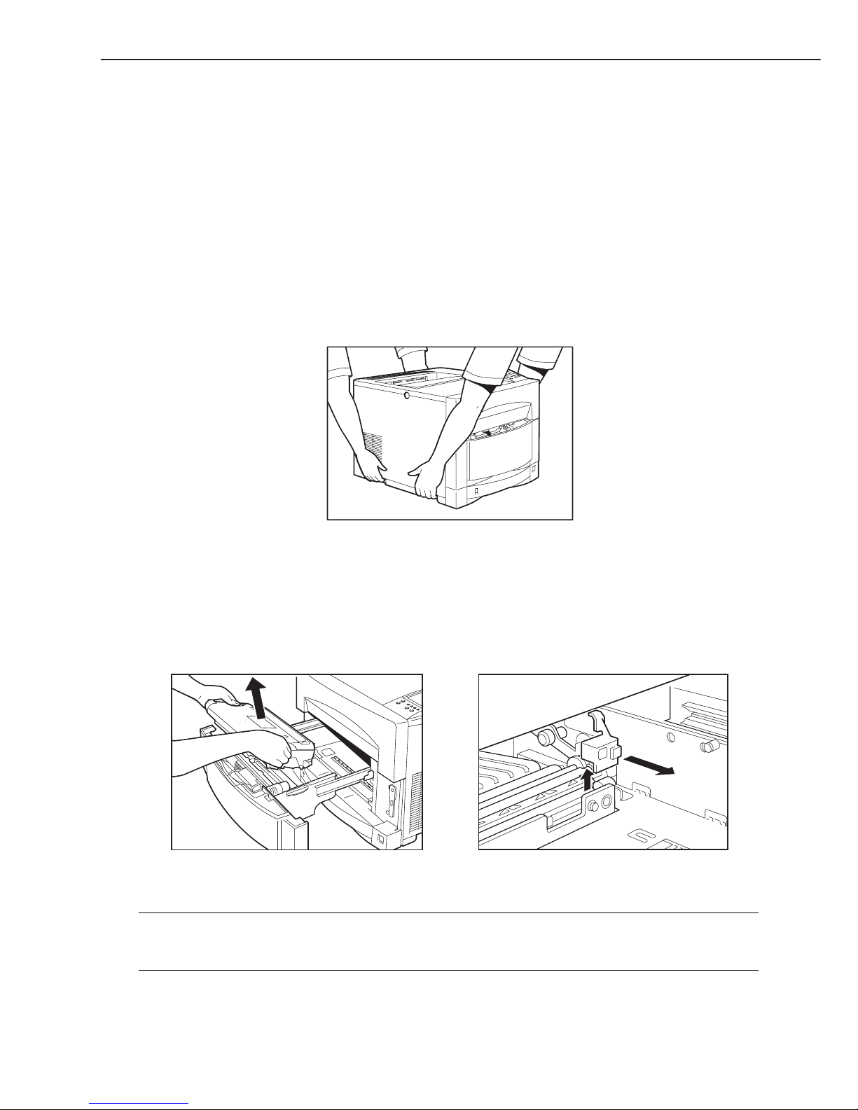
3) Have two persons lift and carry the printer to the installation site. Two persons are required
to move the printer because it weighs about 48 kg.
Fig. 1-5-3
4) Remove the plastic bag from the printer and peel the tape off it. Confirm that the covers
were not damaged or deformed during transport.
5) Remove the universal cassette from the printer and remove the packing material.
6) Open the ITB unit drawer and remove the tape and packing material.
7) Take out the ITB unit and remove the packing material of the secondary transfer roller.
Fig. 1-5-4
Note: When connecting the printer to the computer, make sure to turn them OFF and unplug
the power cord from the power outlet before connecting (disconnecting) the interface in
order to prevent accidents and damages.
1 - 15
CHAPTER 1
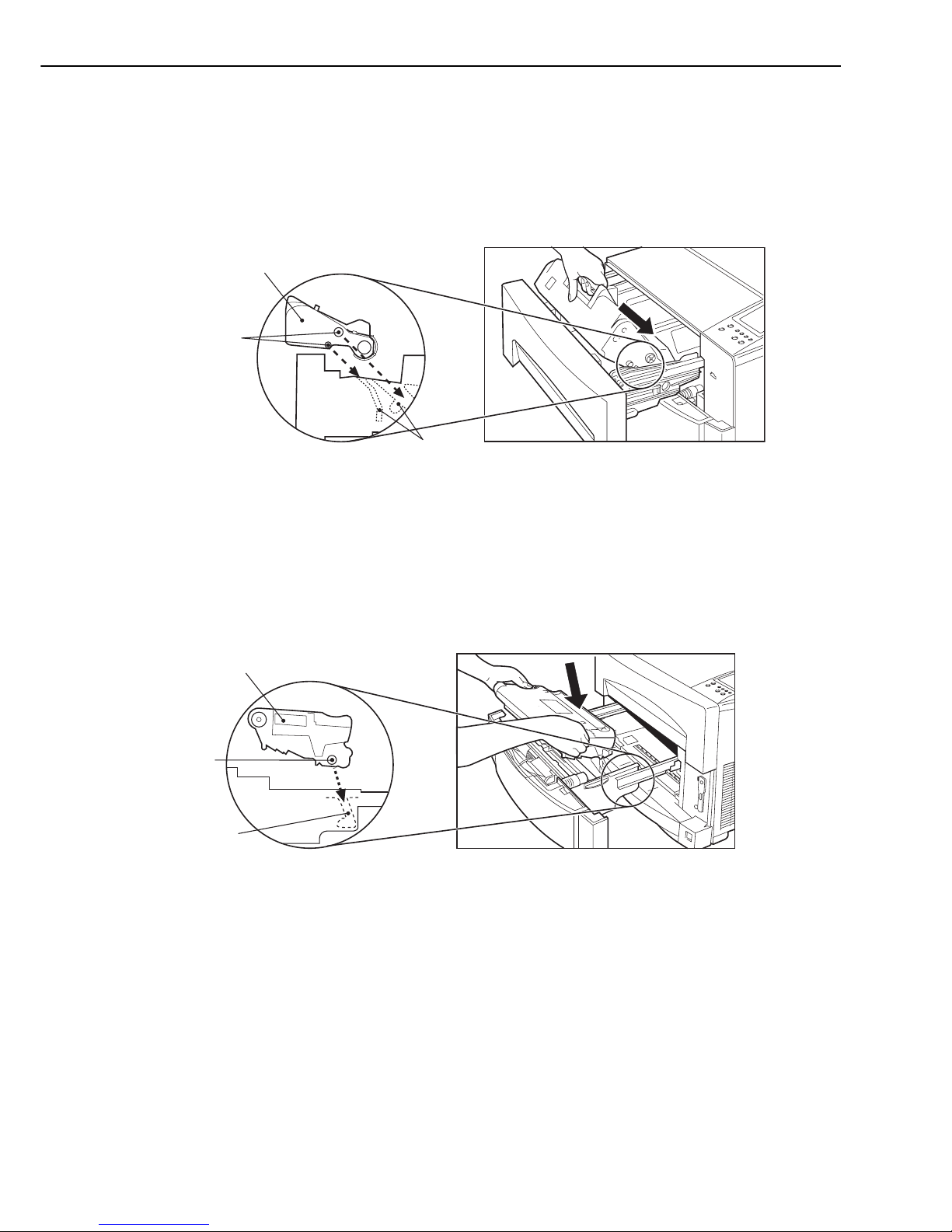
2. Unpacking and installing the drum cartridge
1) Open the drum cartridge drawer.
2) Remove the drum cartridge out of its protection bag.
3) Remove the protective tape from the drum cartridge.
4) Insert the drum cartridge into the printer. Be careful not to damage the photosensitive
drum.
Fig. 1-5-5
5) Close the drum cartridge drawer.
3. Unpacking and installing the ITB unit
1) Open the ITB unit drawer.
2) Insert the ITB unit.
Fig. 1-5-6
3) Close the ITB unit drawer.
4. Unpacking and installing the toner cartridge
This printer can execute the toner cartridge replacement function according to the instruction
from the video controller.
This function detects whether the toner cartridges are installed or not and rotates the developing rotary so that the compartment of the missing toner cartridge comes to the installation slot.
Detection and installation of toner cartridges are conducted in order of Bk, M, C and Y.
1 - 16
CHAPTER 1
Boss
Guide
Drum cartridge
ITB unit
Boss
Guide
Note: Refer to “B. Removal of toner cartridge with manual operation” on page 3-2 when replac-
ing the toner cartridge without using the toner cartridge replacement function.
1) Insert one end of the power cord into the printer and the other end into the outlet. Be sure
to use the supplied power cord.
2) Install the drum cartridge and ITB unit, then turn the printer ON.
Note: The toner cartridge replacement function does not become effective unless the printer is
turned on with the drum cartridge and the ITB unit in it. Install the drum cartridge and
the ITB unit in the printer, then turn it ON.
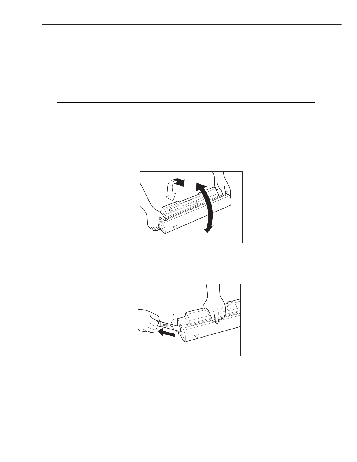
3) Remove the toner cartridge out of its protection bag.
4) Hold the cartridge as shown in Fig. 1-5-7 and slowly rock it up and down five or six times to
distribute toner evenly.
Fig. 1-5-7
5) Place the cartridge on a level surface. Hold down the top of the cartridge with one hand and
pull out the tab with the other hand to remove the sealing tape. (See Fig. 1-5-8)
Fig. 1-5-8
1 - 17
CHAPTER 1
45
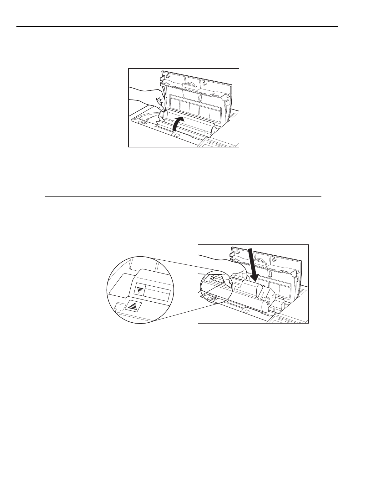
6) Push the top cover unlock button and open the top cover.
7) Open the toner cartridge compartment cover.
Fig. 1-5-9
Note: At this point, the compartment of the black toner cartridge is stopped at the installation
slot by the toner cartridge replacement function.
8) Check the marker and choose the toner cartridge with the same color as the marker. (Install
the black toner cartridge first.)
9) Verify that the printer position mark is aligned with the arrow mark on the toner cartridge
and install the cartridge in the printer.
Fig. 1-5-10
1 - 18
CHAPTER 1
Arrow mark
Position mark
TonerCartridge
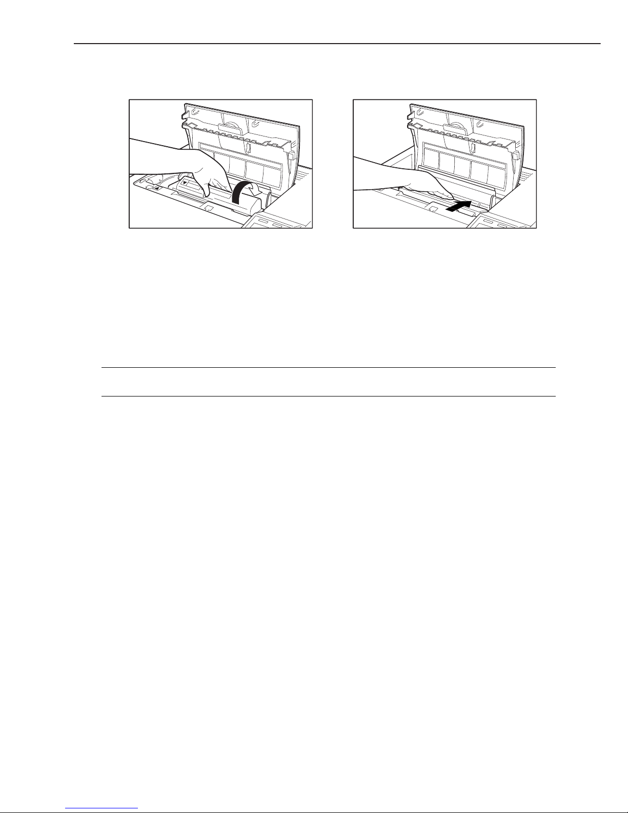
10) Turn the toner cartridge in the direction of the arrow until it stops.
Fig. 1-5-11
11) Close the toner cartridge compartment cover, then close the top cover.
12) When the top cover is closed, the rotary starts to rotate and stops at the next toner cartridge (Magenta) installation position automatically.
You can also rotate the rotary to the next toner cartridge installation position by pressing the
ROTATE key on the control panel. (Note)
13) Repeat steps 3 to 12 to install the other toner cartridges in the printer.
Note: The ROTATE key is used to removed toner cartridges. However, it is not effective when
the printer is not READY.
1 - 19
CHAPTER 1
5. Unpacking and installing the duplexing unit
1) Unpack the duplexing unit and remove the carton.
2) Take out the accessories.
3) Remove the plastic bag covering the duplexing unit and remove adhesive tapes.
4) Remove the packing materials from the duplexing unit.
5) Place the duplexing unit on a flat surface.
6) Install the printer on the duplexing unit, aligning the duplexing unit positioning dowels with
the printer positioning holes.
Fig. 1-5-12
7) Plug the pig tail of the duplexing unit into the outlet of the printer.
Note: If the printer is ON, turn it OFF and unplug the power cable before installing the duplex-
ing unit.
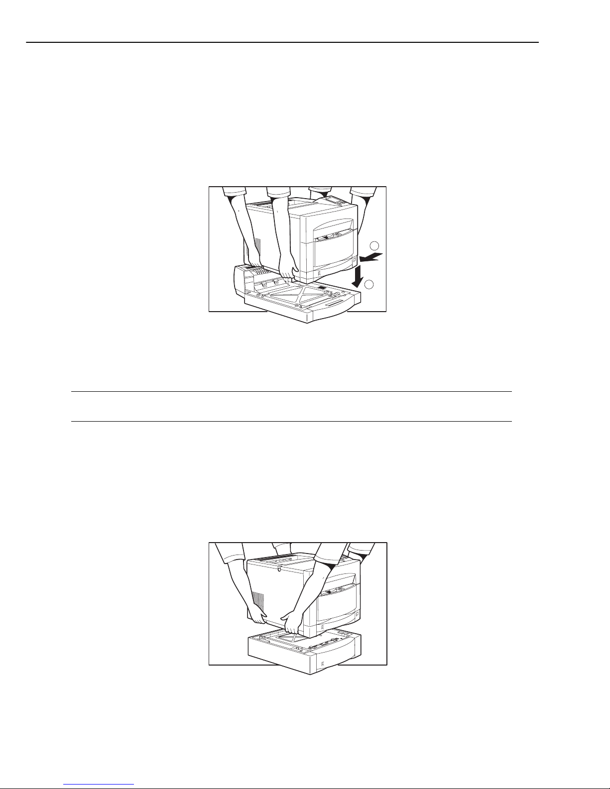
6. Unpacking and installing the paper feeder
1) Unpack the paper feeder and remove the carton.
2) Remove the tape holding the cassette from the paper feeder.
3) Remove the cassette from the paper feeder. Remove the packing materials.
4) Place the paper feeder on a flat surface.
5) Install the printer on the paper feeder, aligning the paper feeder positioning dowels with the
printer positioning holes.
Fig. 1-5-13
1 - 20
CHAPTER 1
1
2
 Loading...