

Canon Booklet Trimmer-A1 Service Manual
BOOKLET
TRIMMER-A1
REVISION 0
FEB. 2002
COPYRIGHT
©
2002 CANON INC. 2000 CANON BOOKLET TRIMMER-A1 REV.0 FEB. 2002 PRINTED IN U.S.A. (IMPRIME AU U.S.A.)
FY8-13HG-000

Application
This manual has been issued by Canon Inc. for qualified persons to learn technical
theory, installation, maintenance, and repair of products. This manual covers all
localities where the products are sold. For this reason, there may be information in this
manual that does not apply to your locality.
Corrections
This manual may contain technical inaccuracies or typographical errors due to
improvements or changes in products. When changes occur in applicable products or in
the contents of this manual, Canon will release technical information as the need arises.
In the event of major changes in the contents of this manual over a long or short period,
Canon will issue a new edition of this manual.
The following paragraph does not apply to any countries where such provisions are
inconsistent with local law.
Trademarks
The product names and company names used in this manual are the registered
trademarks of the individual companies.
Copyright
This manual is copyrighted with all rights reserved. Under the copyright laws, this
manual may not be copied, reproduced or translated into another language, in whole or
in part, without the written consent of Canon Inc.
COPYRIGHT © 2002 CANON INC.
Printed in U.S.A.
Imprimé au U.S.A.
Caution
Use of this manual should be strictly supervised to avoid disclosure of confidential information.
COPYRIGHT© 2002 CANON INC. 2000 CANON BOOKLET TRIMMER-A1 REV.0 FEB. 2002
INTRODUCTION
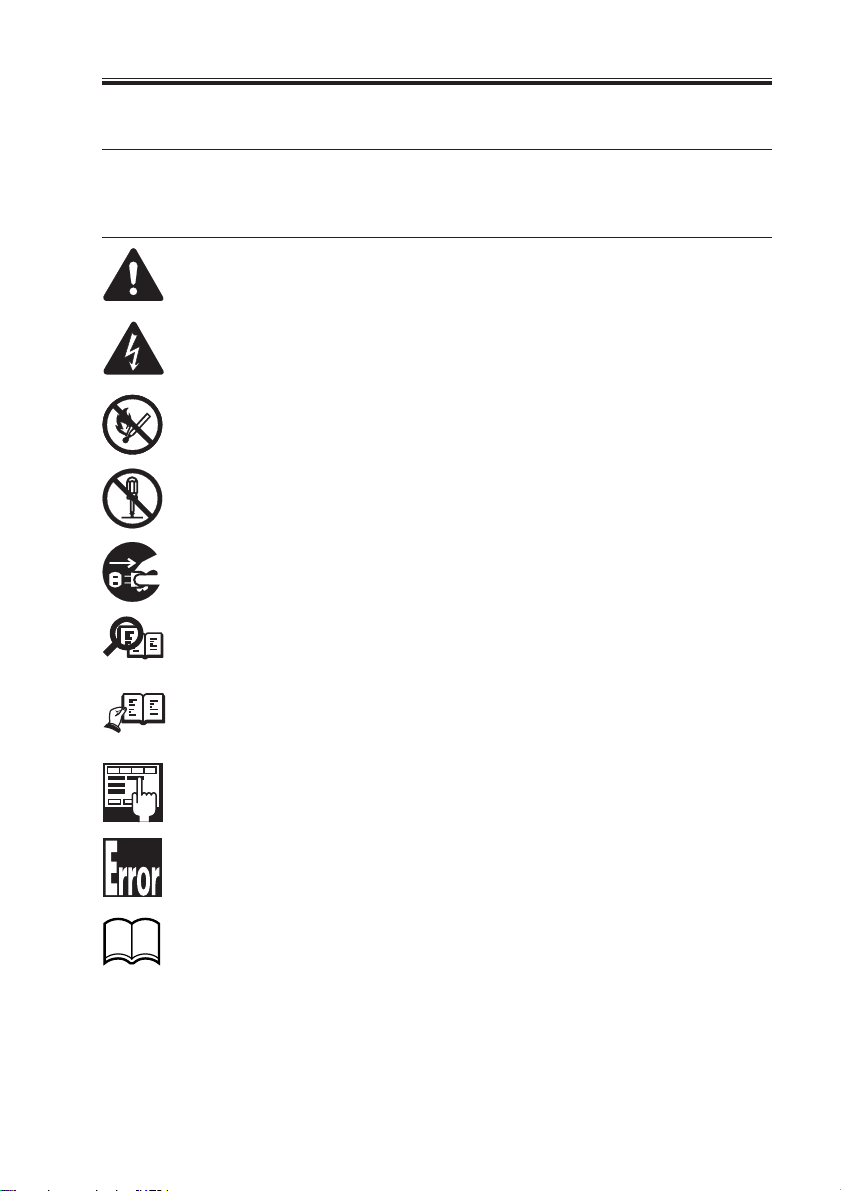
1 Symbols Used
This documentation uses the following symbols to indicate special information:
Symbol Description
Indicates an item of a non-specific nature, possibly classified as Note, Caution,
or Warning.
Indicates an item requiring care to avoid electric shocks.
Indicates an item requiring care to avoid combustion (fire).
Indicates an item prohibiting disassembly to avoid electric shocks or problems.
Indicates an item requiring disconnection of the power plug from the electric
outlet.
Indicates an item intended to provide notes assisting the understanding of the
Memo
topic in question.
Indicates an item of reference assisting the understanding of the topic in ques-
REF.
tion.
Provides a description of a service mode.
Provides a description of the nature of an error indication.
Refers to the Copier Basics Series for a better understanding of the contents.
COPYRIGHT© 2002 CANON INC. 2000 CANON BOOKLET TRIMMER-A1 REV.0 FEB. 2002
i

INTRODUCTION
2 Outline of the Manual
This Service Manual provides basic facts and figures about the BOOKLET TRIMMERA1 needed to service the machine in the field, ensuring product quality and machine functions.
This Service Manual consists of the following chapters:
Chapter 1 General Description: features, specifications, parts names, op-
eration mode, machine operation, basic
construction
Chapter 2 Basic Operations: basic operation, mechanism control
Chapter 3 Mechanical Systems: disassembly/assembly, adjustment
Chapter 4 Maintenance and Inspection: periodically replaced parts, periodically
cleaned parts, periodically inspected parts
Chapter 5 Troubleshooting: PCBs software upgrading, error code, jam
code
Chapter 6 Appendix: general circuit diagram, timing chart
User Mode
Service Mode
This Service manual does not contain instructions on the installation of the machine. For
installation, refer to the Installation Procedure that comes with the machine.
ii
COPYRIGHT© 2002 CANON INC. 2000 CANON BOOKLET TRIMMER-A1 REV.0 FEB. 2002

INTRODUCTION
The following rules apply throughout this Service Manual:
1. Each chapter contains sections explaining the purpose of specific functions and the
relationship between electrical and mechanical systems with reference to the timing
of operation.
In the diagrams,
accompanies the symbol
represents the path of mechanical drive; where a signal name
, the arrow indicates the direction of the electric signal.
The expression “turn on the power” means flipping on the power switch, closing the
front door, and closing the delivery unit door, which results in supplying the machine
with power.
2. In the digital circuits, ‘1’ is used to indicate that the voltage level of a given signal is
“High,” while ‘0’ is used to indicate “Low.” (The voltage value, however, differs from
circuit to circuit.) In addition, the asterisk (*) as in “DRMD*” indicates that the
DRMD signal goes on when ‘0’.
In practically all cases, the internal mechanisms of a microprocessor cannot be
checked in the field. Therefore, the operations of the microprocessors used in the machines are not discussed: they are explained in terms of from sensors to the input of
the DC controller PCB and from the output of the DC controller PCB to the loads.
The descriptions in this Service Manual are subject to change without notice for
product improvement or other purposes, and major changes will be communicated in
the form of Service Information bulletins.
All service persons are expected to have a good understanding of the contents of this
Service Manual and all relevant Service Information bulletins and be able to identify
and isolate faults in the machine.
COPYRIGHT© 2002 CANON INC. 2000 CANON BOOKLET TRIMMER-A1 REV.0 FEB. 2002
iii

CONTENTS
Contents
CHAPTER 1 GENERAL DESCRIPTION
1 Features and Functions ....................... 1-1
2 Specifications ...................................... 1-2
3 Names of Parts .................................... 1-3
3.1 External View ............................. 1-3
3.2 Cross Section ............................. 1-5
4 Oparation Mode .................................. 1-6
4.1 Outline ....................................... 1-6
4.2 Particulars .................................. 1-6
4.3 Making Selections ..................... 1-6
4.4 Others ......................................... 1-6
5 Using the machine .............................. 1-7
5.1 Control Panel ............................. 1-7
CHAPTER 2 BASIC OPERATIONS
1 Basic Operation .................................. 2-1
1.1 Outline ....................................... 2-1
1.1.1 Feeding the Booklet............. 2-1
1.1.2 Feeding to the Cutting Position
(trim mode only) .................. 2-2
1.1.3 Booklet Press
(trim mode only) .................. 2-3
1.1.4 Cutting (trim mode only)..... 2-4
1.1.5 Releasing the Pressing/
Releasing the Stopper
(trim mode only) .................. 2-5
1.1.6 Paper exiting
(trim mode only) .................. 2-6
2 Controlling the Parts ........................... 2-8
2.1 Controlling the Feeding
Assembly ................................... 2-8
2.1.1 Construction ........................ 2-8
2.1.2 Mechanisms ......................... 2-9
2.1.3 Controlling the Feeding
Assembly ........................... 2-10
2.2 Controlling the Pressing
Assembly ................................. 2-13
2.2.1 Construction ...................... 2-13
2.2.2 Mechanisms ....................... 2-15
5.2 Removing a Jam ......................... 1-8
5.2.1 Correcting the Overstacking
Error ................................... 1-13
5.2.2 Collecting and Disposing of
Waste Paper ....................... 1-15
6 Basic Construction ............................ 1-16
6.1 Functional Construction .......... 1-16
6.2 Outline of the Electrical
Circuitry ................................... 1-17
6.3 Wiring Between Options.......... 1-18
6.4 Trimmer Power Supply ............ 1-19
2.2.3 Shifting and Releasing the
Stopper ............................... 2-15
2.2.4 Controlling the Pressing of
the Booklet ......................... 2-17
2.2.5 Controlling the Stopper/
Press ................................... 2-18
2.3 Controlling the Trimmer
Assembly ................................. 2-21
2.3.1 Construction ...................... 2-21
2.3.2 Mechanisms ....................... 2-23
2.3.3 Controlling the Trimming
Operation ........................... 2-23
2.3.4 Removing
the Waste Paper .................. 2-24
2.3.5 Controlling the Trimmer .... 2-24
2.3.6 Removing
the Waste Paper .................. 2-26
2.4 Stacker Assembly ..................... 2-28
2.4.1 Construction ...................... 2-28
2.4.2 Mechanisms ....................... 2-29
2.4.3 Delivery ............................. 2-30
2.4.4 Upright Stacking................ 2-32
2.4.5 Controlling the Delivery/
Stacking Operation ............ 2-34
iv
COPYRIGHT© 2002 CANON INC. 2000 CANON BOOKLET TRIMMER-A1 REV.0 FEB. 2002

CHAPTER 3 MECHANICAL SYSTEMS
0 Before Disassembling the Machine .... 3-1
0.1 Removing the Power Cord ......... 3-1
0.2 Checking the Operation After
Re-assembly ............................... 3-1
1 External Covers .................................. 3-2
1.1 Removing the Front Cover ........ 3-2
1.2 Removing the Upper Cover ....... 3-2
1.3 Removing the Rear Cover .......... 3-3
1.4 Removing the Right Front
Cover 2 ....................................... 3-4
2 Feeding Assembly + Cutter
Assembly ............................................ 3-5
2.1 Removing the Fan Motor Unit
(M108) ....................................... 3-5
2.2 Removing the Feeding Belt from
the Upper Feeding Assembly ..... 3-6
2.3 Removing the Feeding Belt from
the Lower Feeding Assembly .... 3-8
2.4 Removing the sensors at the Lower
Feeding Assembly: Waste Bin Full
Sensor (PS109), and Inlet Sensor
(PS101) .................................... 3-10
2.5 Removing the Cutter Blade
(upper, lower) ........................... 3-11
3 Control Panel .................................... 3-14
3.1 Removing the Trimmer ROM ... 3-14
3.2 Removing the Control Panel ..... 3-15
3.3 Removing the Trimmer DC
Controller PCB ........................ 3-16
4 Stacker Assembly.............................. 3-17
4.1 Removing the Stacker
Assembly ................................. 3-17
4.2 Removing the Pusher Motor and
the Pusher Sensor (PS112) ...... 3-19
4.3 Removing the Vertical Feeding
Roller Rubber ........................... 3-22
4.4 Removing the Stacker Cover Sensor
(PS114) and the Stacker Cover
Switch (MS3, MS4) ................. 3-23
5 Press Assembly ................................. 3-25
5.1 Removing the Upper Press
Assembly ................................. 3-25
5.2 Removing the Upper Press
Assembly Feeding Belt ............ 3-26
COPYRIGHT© 2002 CANON INC. 2000 CANON BOOKLET TRIMMER-A1 REV.0 FEB. 2002
5.3 Removing the Lower Press
Assembly ................................. 3-26
5.3.1 Parallelism Adjustment between
the Folding Face and the
Trimming Face................... 3-29
5.4 Removing the Stopper Motor
(M103) ..................................... 3-30
5.5 Removing the Stopper Release
Motor (M104) .......................... 3-30
5.6 Removing the Feed Sensor
(PS102), Stopper HP Sensor
(PS103), and Stopper Release
HP Sensor (SP104) .................. 3-31
5.7 Removing the Lower Press
Assembly Feeding Belt ............ 3-31
5.8 Removing the Press Motor
(M105) ..................................... 3-32
5.9 Removing the Cutter Motor
(M102) ..................................... 3-33
5.10 Removing the Cutter HP Sensor
(PS106) .................................... 3-35
6 Units at the Rear ............................... 3-36
6.1 Removing the Holder Motor
(M106) ..................................... 3-36
6.2 Removing the Holder Sensor
Unit (Holder upper limit sensor
PS110, Holder lower limit sensor
PS111) ...................................... 3-37
6.2.1 Holder Upper Limit
Sensor Adjustment ............. 3-38
6.2.2 Holder Lower Limit
Sensor Adjustment ............. 3-39
6.3 Removing the Feeding Motor
(M101) ..................................... 3-40
6.4 Removing the Waste Paper Bin
Sensor (PS107) ........................ 3-40
6.5 Removing the Trimmer Drive
PCB .......................................... 3-41
6.6 Removing the Power Supply
Circuit Unit .............................. 3-41
6.7 Removing the Current
Breaker ..................................... 3-42
6.8 Removing the Sensor (press
assembly bottom plate) ............ 3-43
CONTENTS
v

CONTENTS
CHAPTER 4 MAINTENANCE AND INSPECTION
1 Maintenance and Inspection ............... 4-1
1.1 Tools Needed ............................. 4-1
1.2 Periodically Replaced Parts ....... 4-1
1.3 Periodically Cleaned/Inspected
Parts............................................ 4-1
CHAPTER 5 TROUBLESHOOTING
1 Making Adjustments When Replacing
Mechanical/Electrical Parts ................ 5-1
1.1 Trimmer DC Controller PCB ..... 5-1
1.2 Trimmer Drive PCB ................... 5-1
1.3 Lower Press Assembly ............... 5-2
1.4 Holder Upper Limit Sensor and the
Holder Lower Limit Sensor ....... 5-2
1.5 Belt Tension of
the Holder Plate ......................... 5-2
2 Upgrading the Software ...................... 5-3
3 Error Code .......................................... 5-4
4 Jam Code .......................................... 5-12
APPENDIX
USER MODE
1 Construction of User Mode ................ U-1
1.1 Overview ................................... U-1
1.2 Starting User Mode and
Making Selections .................... U-3
1.2.1 Trimmer Control Panel ....... U-3
1.3 Ending User Mode .................... U-4
1.4 Basic Operation ......................... U-4
1.4.1 Trimmer Control Panel
(in user mode) ..................... U-4
1.5 Others ........................................ U-4
1.5.1 Backing Up the Data .......... U-4
2 Details of Items .................................. U-5
2.1 Trim Width Adjustment ............ U-5
2.1.1 Operating from the Host
Machine Control Panel
(operation mode in 'System';
see the descriptions of service
mode items) ........................ U-5
2.1.2 Operating from the Trimmer
Control Panel (operation mode
in 'Local'; see descriptions on
service mode items) ............ U-6
2.1.3 Adjusting the Trim Width ... U-7
2.2 Changing the Display
Language ................................... U-8
vi
COPYRIGHT© 2002 CANON INC. 2000 CANON BOOKLET TRIMMER-A1 REV.0 FEB. 2002

SERVICE MODE
1 Construction of Service Mode ............ S-1
1.1 Outline ....................................... S-1
1.2 Starting Service Mode and
Making Selections ..................... S-2
1.3 Ending Service Mode ................ S-2
1.4 Basic Operation .......................... S-3
1.4.1 Trimmer Control Panel
(in service mode) ................. S-3
1.5 Others .........................................S-3
CONTENTS
1.5.1 Backing Up Data ................. S-3
2 Details of Items ................................... S-4
2.1 Version Indication ......................S-4
2.2 Trim Counter .............................. S-5
2.3 Operation Mode ......................... S-6
2.4 Selecting Factory Setting for
Trim Width .................................S-7
2.5 Motor Test ................................ S-10
2.6 I/O Port Display .......................S-12
COPYRIGHT© 2002 CANON INC. 2000 CANON BOOKLET TRIMMER-A1 REV.0 FEB. 2002
vii

CHAPTER 1
GENERAL DESCRIPTION
COPYRIGHT© 2002 CANON INC. 2000 CANON BOOKLET TRIMMER-A1 REV.0 FEB. 2002

CHAPTER 1 GENERAL DESCRIPTION
1 Features and Functions
The trimmer is equipped with mechanisms to receive a booklet prepared by its host saddle
finisher, trim to smooth its edge, and deposit the result in a stack.
Edge being
trimmed
F01-100-01
COPYRIGHT© 2002 CANON INC. 2000 CANON BOOKLET TRIMMER-A1 REV.0 FEB. 2002
After trimming
1-1
CHAPTER 1 GENERAL DESCRIPTION
2 Specifications
Item Description Remarks
Type w/ stacking mechanism; reciprocating upper
blade; edge trimming device
Number of sheets 30 sheets
to trim (14 sheets of 80 g paper + cover of 200 g paper)
Stack size 200 mm (equivalent of 2,000 sheets of 80 g
paper; 5-fold 100 booklets; 10-fold 50 booklets)
Paper size A3/B4/A4R, Ledger/LetterR
Trimming time 3 sec (approx.)
Trimming 6.3 sec (approx.)
operation time
Minimum trimming 2 mm or more
thickness
Cutter life 500,000 operations or more
Waste paper case 500 sheets (approx.)
capacity
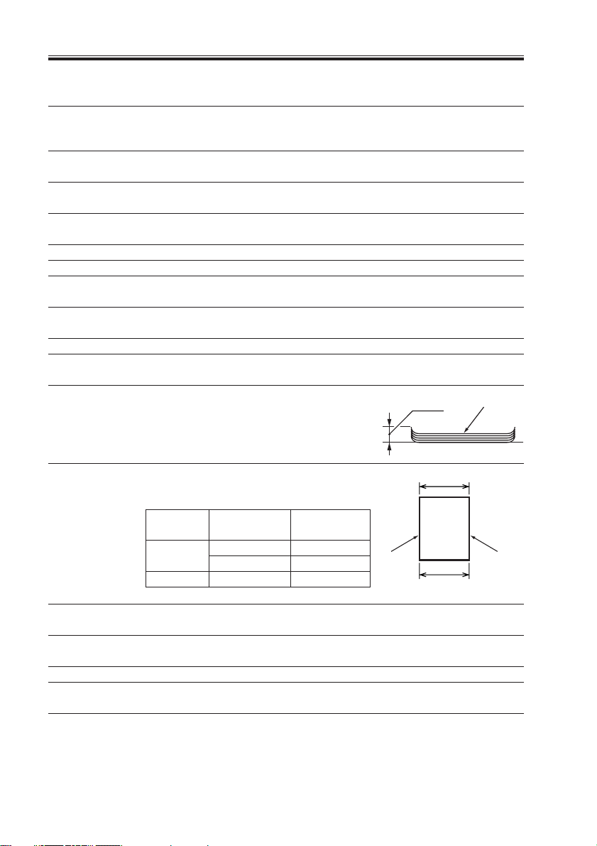
Allowable curling 10 mm max.
(measurement taken of a stack of
5 delivered sheets)
Curl
Sheets
Degree of parallel See the table below.
in relation to folded Degree of parallel = |A-B|
end
Cover
Absent
Present 2 to 15 1.5 mm or less
Operating Temperature: 10°C to 30°C Same as host device
environment Humidity: 10% to 80% RH Same as host device
Size 1321 × 562 × 629 1165 mm
(W × H × D) mm (width of external assembly)
Power supply 100 to 230 V; 50, 60 Hz
Maximum power 300 W (approx.)
consumption
Weight 68 kg (approx.)
Number of Degree of
sheets bound parallel
2 to 5 1.0 mm or less
6 or 15 1.5 mm or less
Fold
A
B
T01-200-01
1-2
COPYRIGHT© 2002 CANON INC. 2000 CANON BOOKLET TRIMMER-A1 REV.0 FEB. 2002
Trimmed
edge
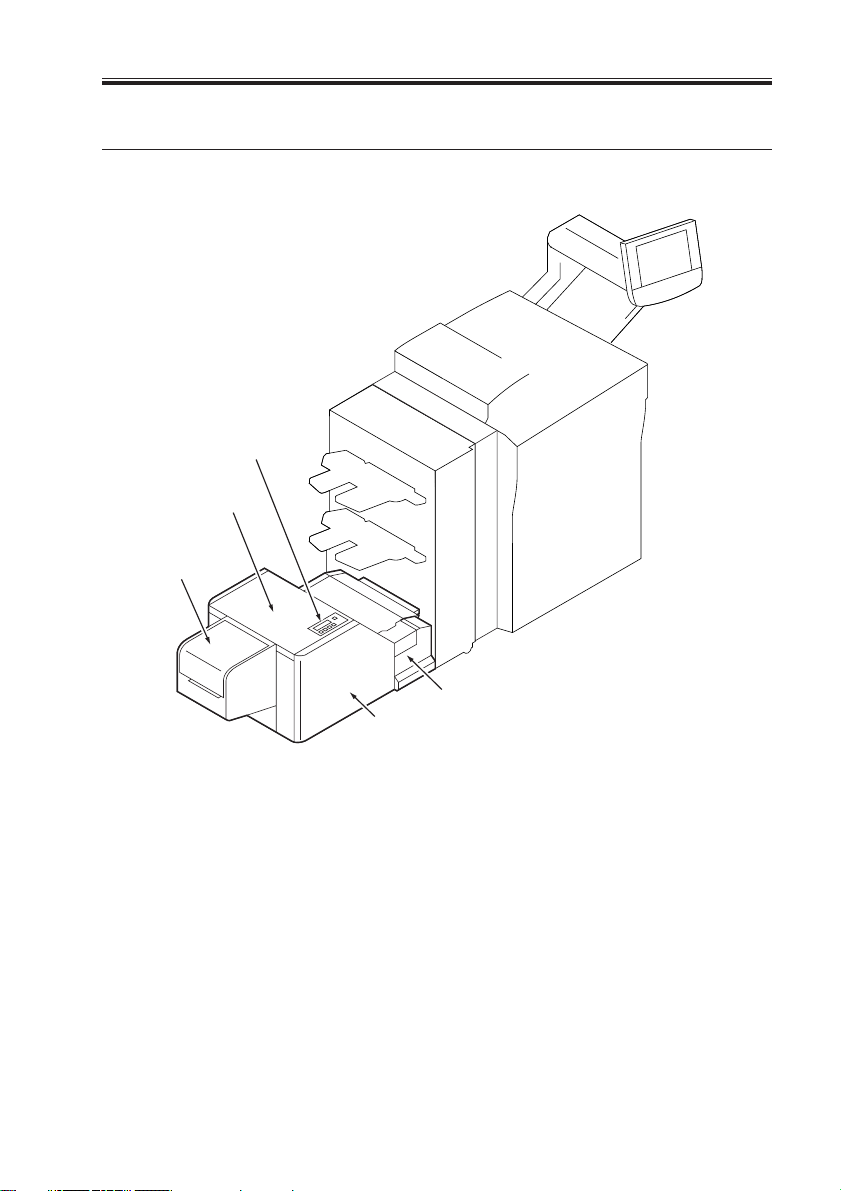
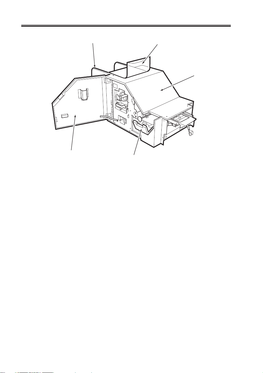
3 Names of Parts
3.1 External View
[1]
[2]
[3]
CHAPTER 1 GENERAL DESCRIPTION
[5]
[4]
[1] Control panel
[2] Trimmer
[3] Stacker cover
F01-301-01
COPYRIGHT© 2002 CANON INC. 2000 CANON BOOKLET TRIMMER-A1 REV.0 FEB. 2002
[4] Front cover
[5] Rigth front cover
1-3
CHAPTER 1 GENERAL DESCRIPTION
[1] Stacker cover
[2] Stacker unit
[3] Front cover
[3]
[2]
[1]
[5]
[4]
[4] Right front cover
[5] Top plate
F01-301-02
1-4
COPYRIGHT© 2002 CANON INC. 2000 CANON BOOKLET TRIMMER-A1 REV.0 FEB. 2002
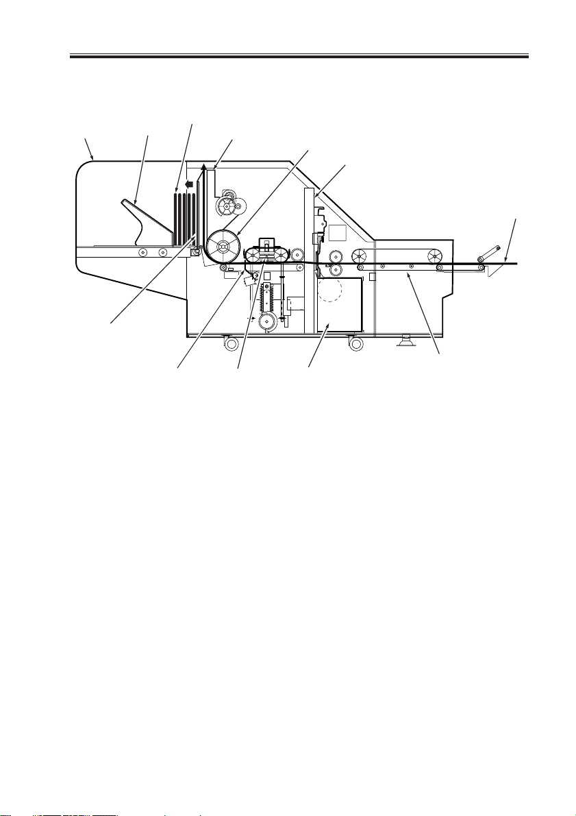
3.2 Cross Section
CHAPTER 1 GENERAL DESCRIPTION
[6]
[5]
[7]
[4]
[8] [9] [10]
[1] Cutter unit
[2] Vertical feeding roller
[3] Pusher unit
[4] Delivered booklets
[5] Delivery tray
[6] Stacker
[3]
[2]
[1]
[12]
[11]
[7] Holder assembly
[8] Stopper assembly
[9] Pressing assembly
[10] Waste paper box
[11] Entrance feeding assembly
[12] Paper path
F01-302-01
COPYRIGHT© 2002 CANON INC. 2000 CANON BOOKLET TRIMMER-A1 REV.0 FEB. 2002
1-5

CHAPTER 1 GENERAL DESCRIPTION
4 Oparation Mode
4.1 Outline
The machine offers 2 operation modes listed below:
Operation Modes
"SYSTEM" mode (Default): Use it to enable/disable trimming, and to adjust the trim-
ming width (These settings are done in the host copier's
control panel).
"LOCAL mode": Use it to enable/disable trimming, and to adjust trimming
width (Theae settings are done in the trimmer's control
panel).
4.2 Particulars
Depending on the selected operation mode, differences exist in relation to the following
items:
Operation mode
"LOCAL" "SYSTEM"
Enabling trimming Possible from trimmer's control Possible from host copier's control
panel panel
Adjusting trimming width Possible from trimmer's control Possible from host copier's control
panel panel
T01-402-01
4.3 Making Selections
Selections can be made in service mode. (See the descriptions for service mode.)
4.4 Others
• The language used in the trimmer's control panel can be changed only from the
trimmer's control panel.
• The language used in the trimmer's control panel is independent of the language used in
its host copier's language (i.e., there is no correlation between the two sets of specifications).
• When the machine is operating in "LOCAL" mode, the commands for "trimming" or
"trimming width adjustment" from the host copier or the driver will not be recognized,
and the operations will be as specified in the trimmer's control panel.
1-6
COPYRIGHT© 2002 CANON INC. 2000 CANON BOOKLET TRIMMER-A1 REV.0 FEB. 2002

5 Using the machine
5.1 Control Panel
CHAPTER 1 GENERAL DESCRIPTION
[1] [2] [3]
Trim
ON/OFF
No. Key operation
1 LCD
2 Trim lamp
3 Trim ON/OFF key
4 Menu key
5 -/< key
6 +/> key
7 Enter key
8 Error lamp
Menu Enter
-/< +/>
[6][5][4]
F01-501-01
Description
Indicates the state of the machine or to
bring up settings screens (e.g., Menu).
LED ON: Trim/ON
LED OFF: Trim/OFF
To be pressed to enable/disable the trim
function.
To be pressed to set/release the menu.
To be pressed when selecting a mode or
changing the cut width.
To be pressed when selecting a mode or
changing the cut width.
TO be pressed to store the settings made.
LED flashing: paper jam, cover open,
stack full, waste paper
box full/not set
fault (service error)
T01-501-01
Error
[8][7]
Remarks
20 characters × 2 lines
Only when LOCAL Mode
A press while setting a mode
will invalidate the settings being made.
The changes made will be in
opposite sequence to the use of
the +/> key.
The changes made will be in
opposite sequence to the use of
the -/< key.
COPYRIGHT© 2002 CANON INC. 2000 CANON BOOKLET TRIMMER-A1 REV.0 FEB. 2002
1-7
CHAPTER 1 GENERAL DESCRIPTION
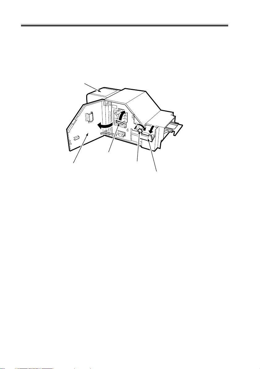
5.2 Removing a Jam
If a booklet jams at the entrance to the feeding assembly, open the front cover and the
right front cover; then, turn the jam releasing knob to remove the jam.
If a booklet jams in the press assembly, open the front cover and keep the press assembly
releasing lever up to remove it.
[5]
[2]
[1]
[3]
[4]
[1] Front cover
[2] Press assembly releasing knob
[3] Jam removal releasing lever
1-8
COPYRIGHT© 2002 CANON INC. 2000 CANON BOOKLET TRIMMER-A1 REV.0 FEB. 2002
[4] Right front cover
[5] Stacker cover
F01-502-01
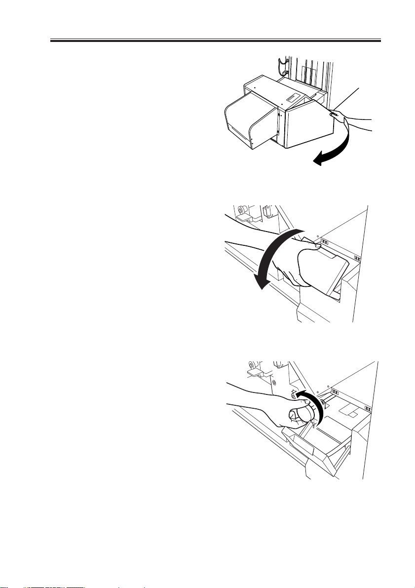
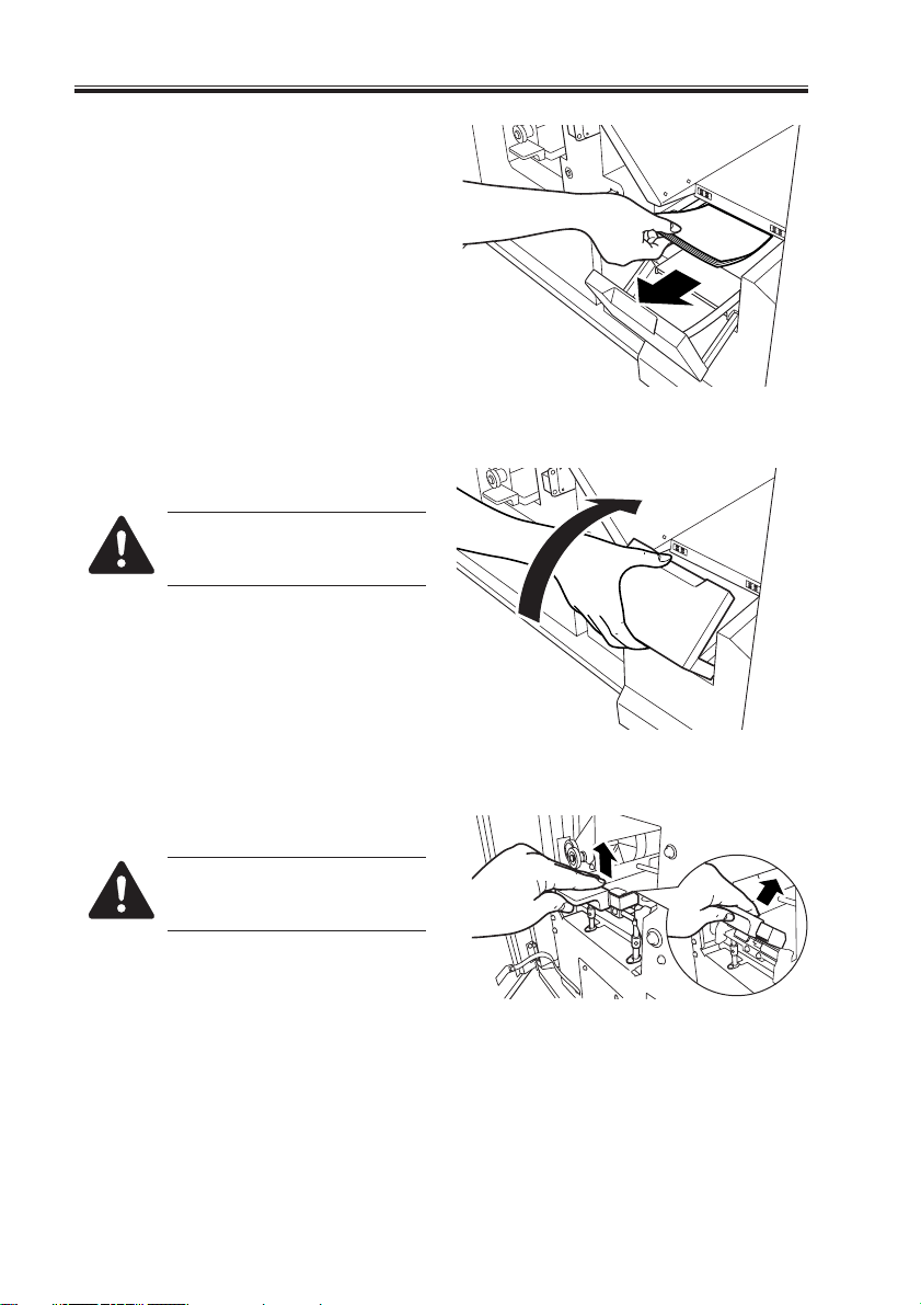
1) Open the front cover.
2) Open the right front cover.
CHAPTER 1 GENERAL DESCRIPTION
F01-502-02
3) Turn the knob of the feeding assembly
counter clockwise.
COPYRIGHT© 2002 CANON INC. 2000 CANON BOOKLET TRIMMER-A1 REV.0 FEB. 2002
F01-502-03
F01-502-04
1-9
CHAPTER 1 GENERAL DESCRIPTION
4) Remove the paper jam.
5) Close the right cover.
When closing the cover, be sure
to take care so as not to trap
your fingers.
F01-502-05
6) Lift the releasing lever.
When lifting the lever, be sure
to take care so as not to trap
your fingers.
1-10
F01-502-06
F01-502-07
COPYRIGHT© 2002 CANON INC. 2000 CANON BOOKLET TRIMMER-A1 REV.0 FEB. 2002
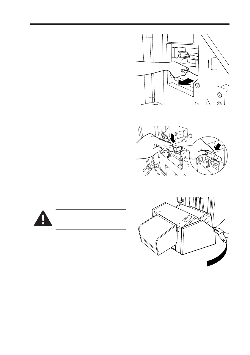
7) Remove the paper jam.
8) Shift the releasing lever back into its
initial position.
CHAPTER 1 GENERAL DESCRIPTION
F01-502-08
F01-502-09
9) Close the front cover.
When closing the cover, be sure
to take care so as not to trap
your fingers.
COPYRIGHT© 2002 CANON INC. 2000 CANON BOOKLET TRIMMER-A1 REV.0 FEB. 2002
F01-502-10
1-11
CHAPTER 1 GENERAL DESCRIPTION
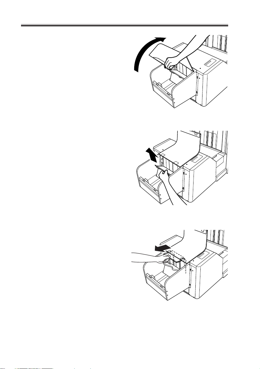
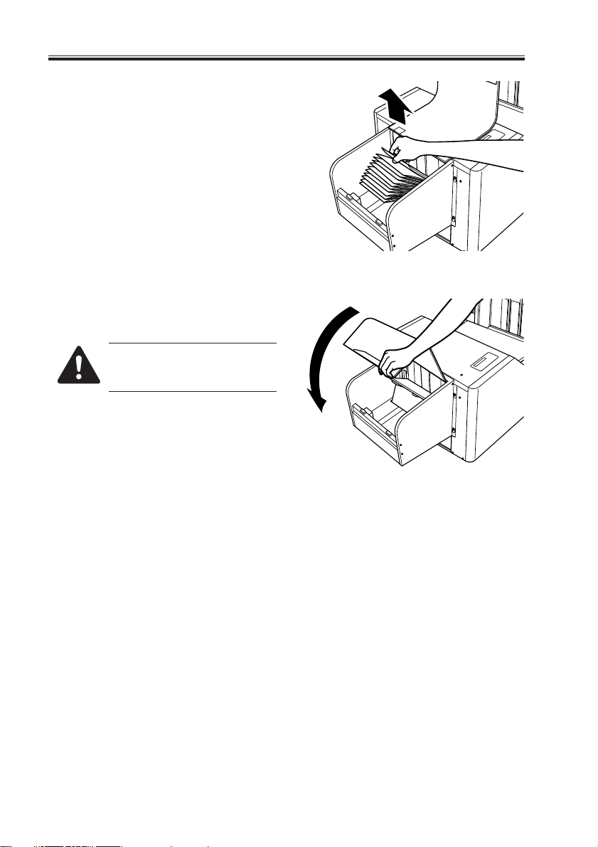
10) Open the stacker cover.
11) Remove the paper from the stacker assembly.
F01-502-11
12) Remove the paper jam from the rear of
the stacker assembly.
1-12
COPYRIGHT© 2002 CANON INC. 2000 CANON BOOKLET TRIMMER-A1 REV.0 FEB. 2002
F01-502-12
F01-502-13
13) Close the stacker cover.
When closing the cover, be sure
to take care so as not to trap
your fingers.
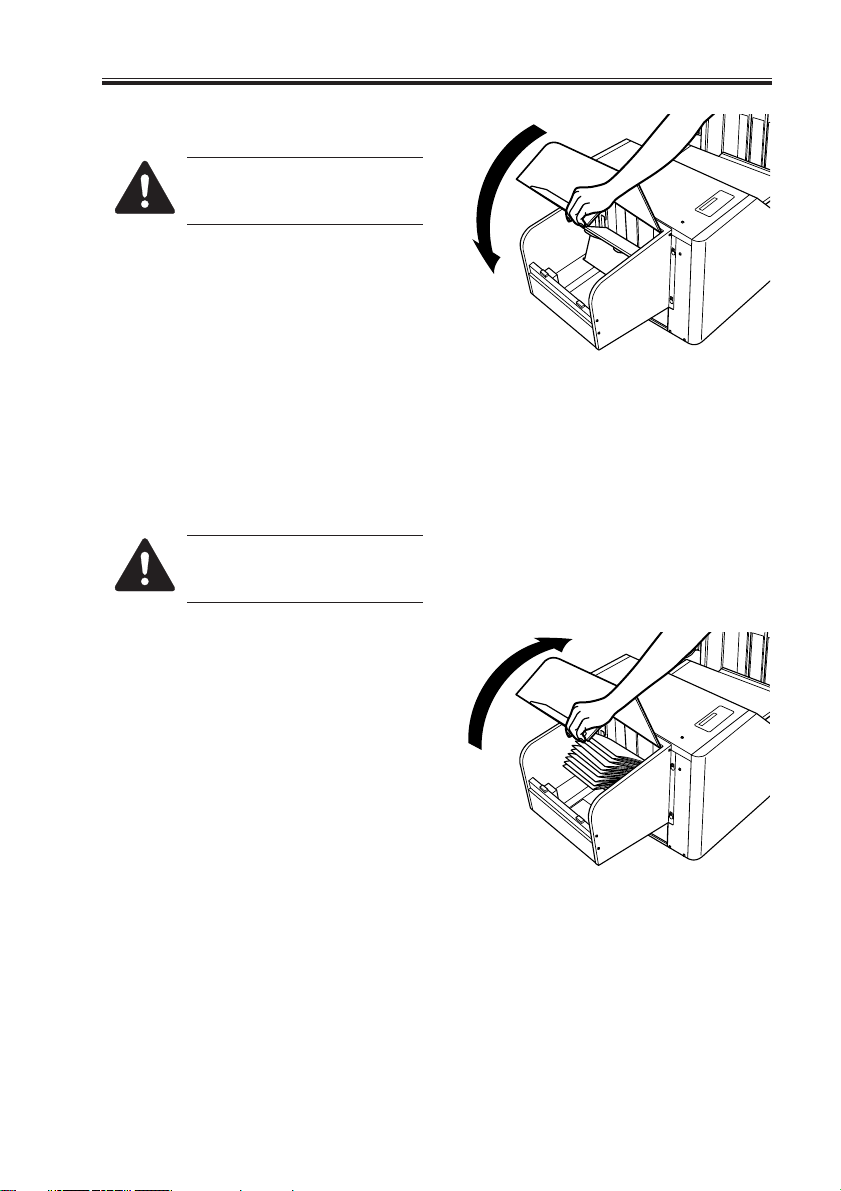
5.2.1 Correcting the Overstacking Error
When the stacker tray overflows with
printouts, the machine will stop its operation. Remove the printouts as follows:
Do not impose a load of 10 kg
or more on the stacker assembly.
1) Open the stacker cover.
CHAPTER 1 GENERAL DESCRIPTION
F01-502-14
COPYRIGHT© 2002 CANON INC. 2000 CANON BOOKLET TRIMMER-A1 REV.0 FEB. 2002
F01-502-15
1-13
CHAPTER 1 GENERAL DESCRIPTION
2) Remove all paper from the stacker assembly.
3) Close the stacker cover. (The job will
resume automatically.)
When closing the cover, be sure
to take care not to trap your fingers.
F01-502-16
1-14
F01-502-17
COPYRIGHT© 2002 CANON INC. 2000 CANON BOOKLET TRIMMER-A1 REV.0 FEB. 2002
CHAPTER 1 GENERAL DESCRIPTION
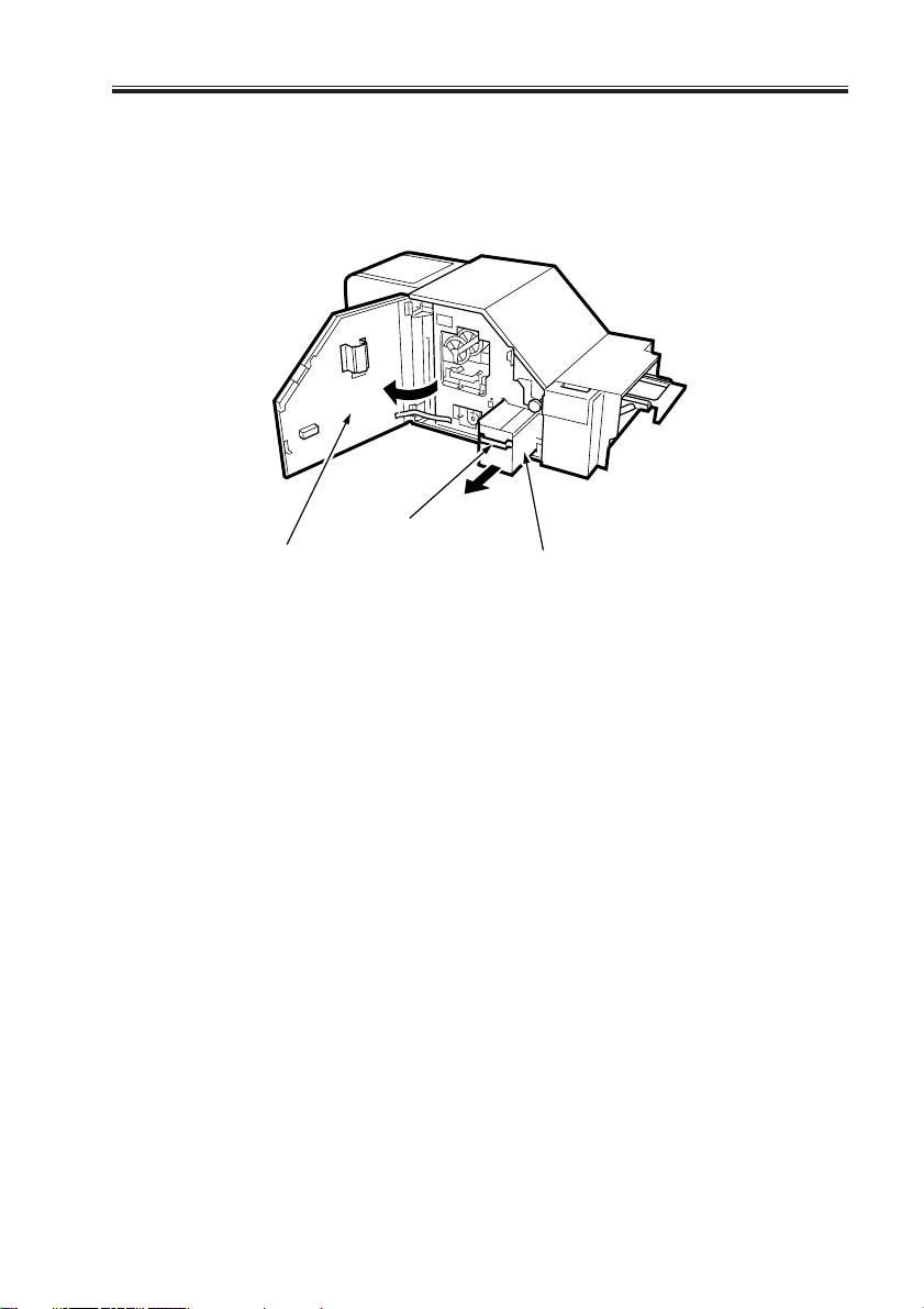
5.2.2 Collecting and Disposing of Waste Paper
The waste paper from cutting operation is collected in a waste paper box. To dispose of
the paper, open the front cover, shift the waste paper box lever, and draw out the waste paper
box.
[2]
[1]
[3]
[1] Front cover
[3] Waste paper box
[2] Waste paper box handle
F01-502-18
COPYRIGHT© 2002 CANON INC. 2000 CANON BOOKLET TRIMMER-A1 REV.0 FEB. 2002
1-15
CHAPTER 1 GENERAL DESCRIPTION
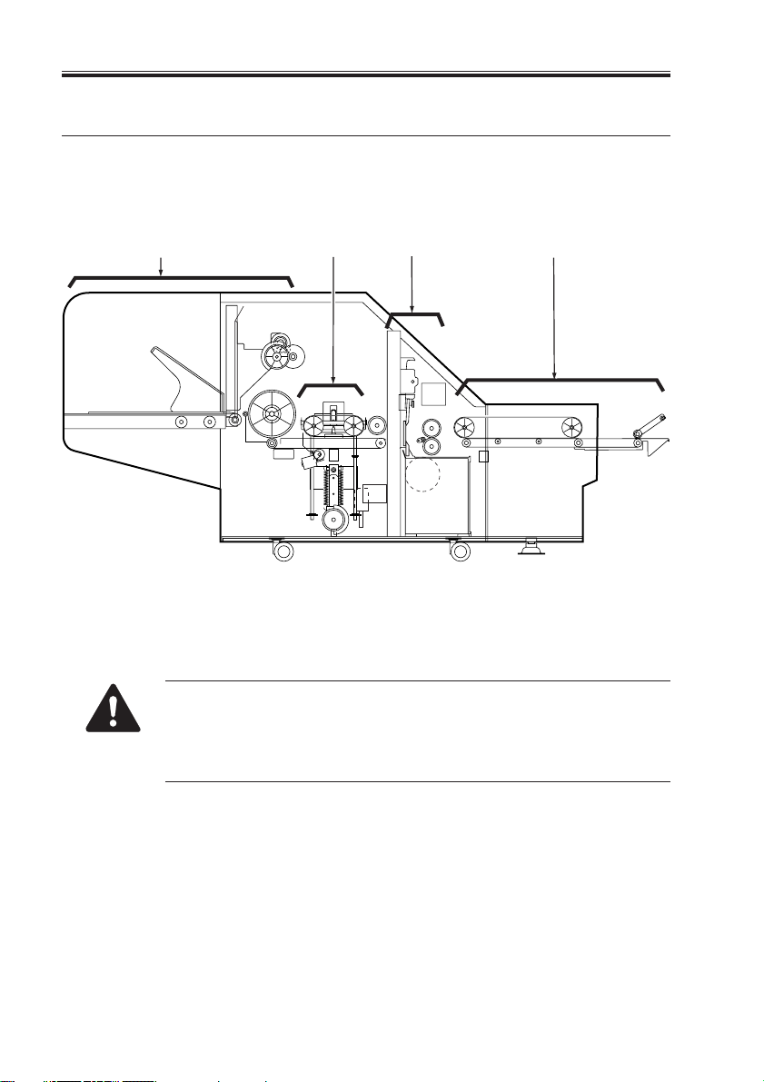
6 Basic Construction
6.1 Functional Construction
As shown in the following diagram, the machine consists of the feeding section, cutter
section, pressing section and stacker section.
[1]
[1] Stacker section
[2] Pressing section
The trim process (i.e. paper feeding process) differs by the trim Designation
Modes; Designating method of the trim designation modes are different between the trim operation modes; in LOCAL mode to be designated in the
trimmer's control panel, in SYSTEM mode to be designated in its host
copier's control panel.
[2] [3]
[3] Cutter section
[4] Feeding section
F01-601-01
[4]
1-16
COPYRIGHT© 2002 CANON INC. 2000 CANON BOOKLET TRIMMER-A1 REV.0 FEB. 2002
CHAPTER 1 GENERAL DESCRIPTION
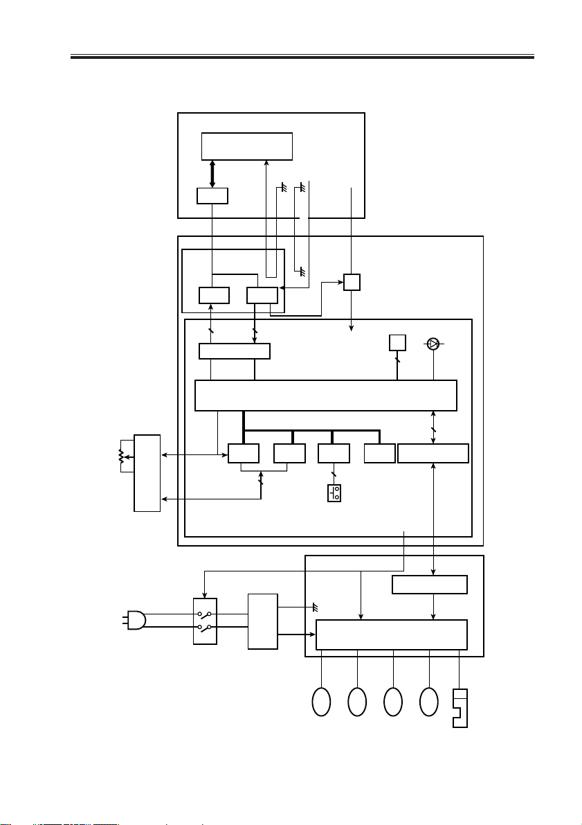
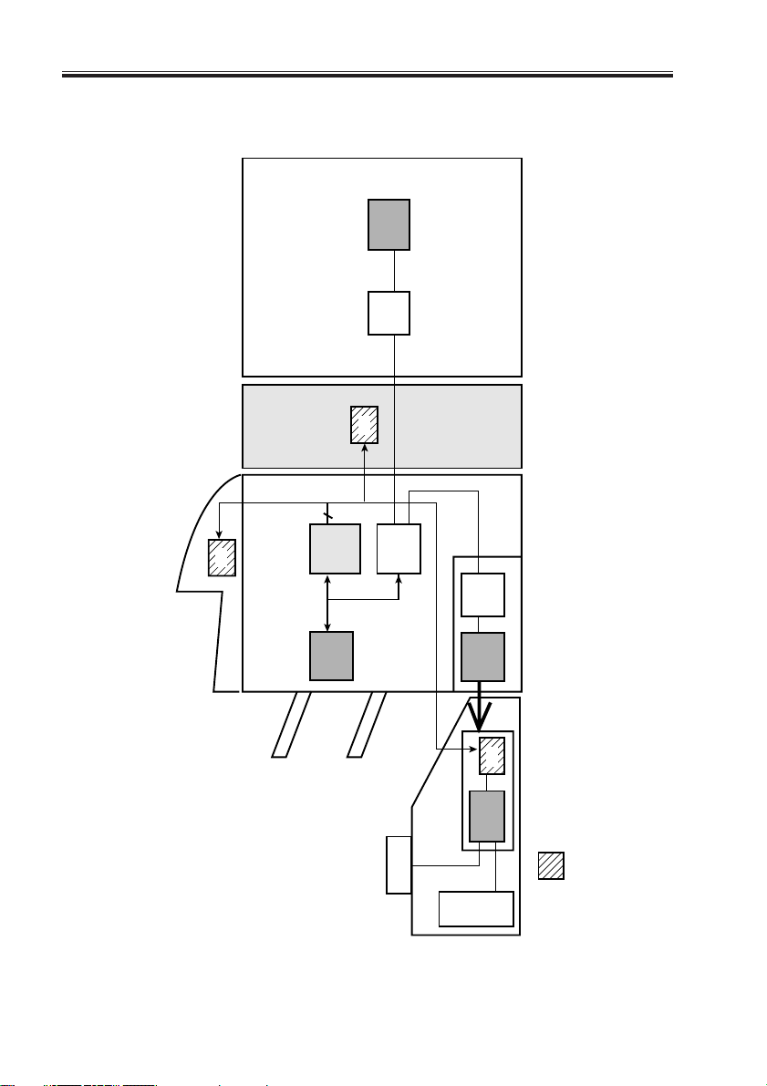
6.2 Outline of the Electrical Circuitry
CPU
LCD
5VF
circuit
Serial
I/O.EXP
8
Interface circuit
RS
Eclk,R/W,
controller
Serial I/O.EXP
Trimmer connection
Serial
I/O.EXP
7
LCD
WR I/F
detection
LCD
RD I/F
D7~D0
Saddle finisher
5VF
Powe r
ON/OFF
Trimmer CPU
Key IN
I/F
5
24V
5Vtrm
DC-DC converter
EPROM
(1Mbit)
4
EEPROM
38
Interface circuit
5Vtrm
Interface circuit
Trimmer control
panel and
controller PCB
Error indicator LED
5Vtrm circuit
unit
Power supply
Motor driver
sensor I/F circuit
24Vtrm
PM
1 pc.
6 pc.
Motor
Motor
DCBM
F01-602-01
COPYRIGHT© 2002 CANON INC. 2000 CANON BOOKLET TRIMMER-A1 REV.0 FEB. 2002
Motor
Fan
1 pc.
DCBLM
motor
1 pc.
Trimmer driver PCB
15 pc.
Sensor
1-17
CHAPTER 1 GENERAL DESCRIPTION
6.3 Wiring Between Options
CPU
Printer
IPC
Inserter
1 pc.
4
Serial I/O
CPU bus
controller
CPU
1 pc.
Trimmer
IPC
Display
Z-folding
IPC
CPU
2 pc.
CPU
Trimmer controller
Driver PCB
Saddle finisher
Serial-to-parallel IC
1-18
F01-603-01
COPYRIGHT© 2002 CANON INC. 2000 CANON BOOKLET TRIMMER-A1 REV.0 FEB. 2002
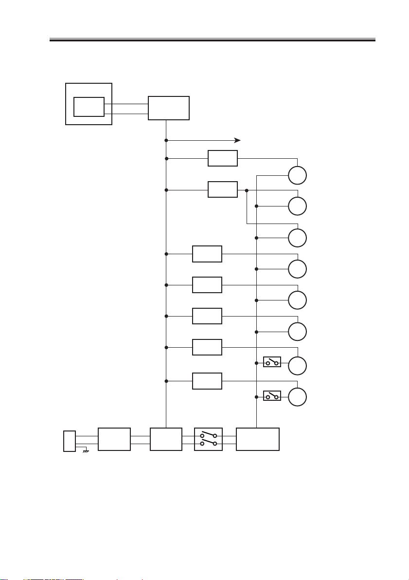
6.4 Trimmer Power Supply
Finisher
Powe r
supply
+24VL
+5R
Regulator
circuit
+5V
Driver
Driver
Driver
Driver
CHAPTER 1 GENERAL DESCRIPTION
Sensors
Driver
M101
Driver
Feeding motor
M102
Cutter motor
M108
Waste paper removal
fan motor
M103
Stopper motor
M104
Stopper release
motor
M105
Press motor
Stacker cover
Driver
switch
Stacker cover
switch
+24VP
DC power
supply
Power plug
Circuit
breaker
Relay
Front cover
switch
F01-604-01
COPYRIGHT© 2002 CANON INC. 2000 CANON BOOKLET TRIMMER-A1 REV.0 FEB. 2002
M106
Holder motor
M107
Pusher motor
1-19

CHAPTER 2
BASIC OPERATIONS
COPYRIGHT© 2002 CANON INC. 2000 CANON BOOKLET TRIMMER-A1 REV.0 FEB. 2002
 Loading...