

Canon Booklet Finisher-D1, Staple Finisher-D1 Service Manual

Staple Finisher-D1 / Booklet Finisher-D1
Product Outline
Technology
Periodic Servicing
Parts Replacing and Cleaning
Adjustment
Troubleshooting
Installation
Appendix
Service Manual Rev. 01
7654321

Application
This manual has been issued by Canon Inc. for qualied persons to learn technical theory,
installation, maintenance, and repair of products. This manual covers all localities where the
products are sold. For this reason, there may be information in this manual that does not
apply to your locality.
Corrections
This manual may contain technical inaccuracies or typographical errors due to improvements
or changes in products. When changes occur in applicable products or in the contents of this
manual, Canon will release technical information as the need arises. In the event of major
changes in the contents of this manual over a long or short period, Canon will issue a new
edition of this manual.
The following paragraph does not apply to any countries where such provisions are
inconsistent with local law.
Trademarks
The product names and company names used in this manual are the registered trademarks
of the individual companies.
Copyright
This manual is copyrighted with all rights reserved. Under the copyright laws, this manual may
not be copied, reproduced or translated into another language, in whole or in part, without the
consent of Canon Inc.
© CANON INC. 2012
Caution
Use of this manual should be strictly supervised to avoid disclosure of condential
information.
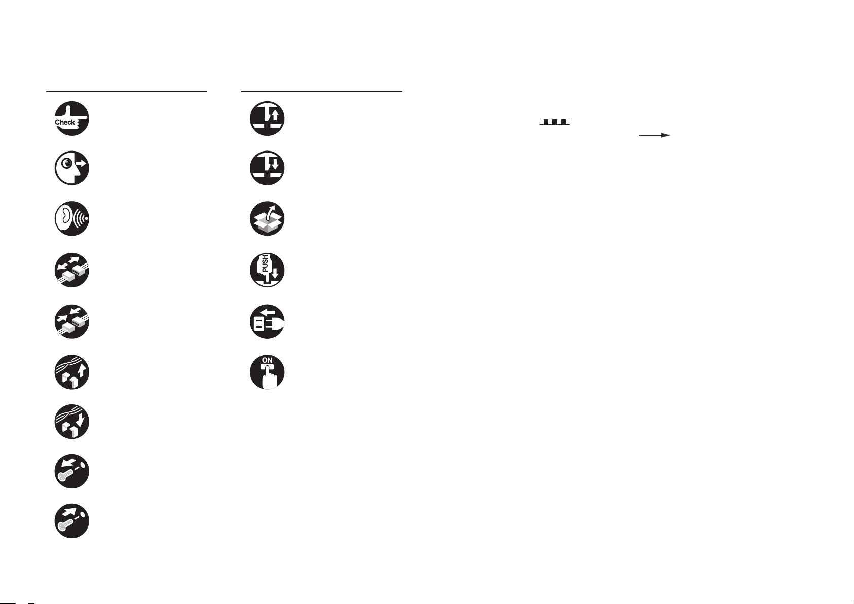
Explanation of Symbols
The following symbols are used throughout this Service Manual.
Symbols Explanation Symbols Explanation
Check.
Check visually. Insert the claw.
Remove the claw.
The following rules apply throughout this Service Manual:
1. Each chapter contains sections explaining the purpose of specic functions and the
relationship between electrical and mechanical systems with reference to the timing of
operation.
In the diagrams, represents the path of mechanical drive; where a signal
name accompanies the symbol, the arrow
indicates the direction of the
electric signal.
The expression "turn on the power" means ipping on the power switch, closing the
front door, and closing the delivery unit door, which results in supplying the machine with
power.
Check the noise. Use the bundled part.
Disconnect the connector. Push the part.
Connect the connector. Plug the power cable.
Remove the cable/wire
from the cable guide or wire
saddle.
Set the cable/wire to the
cable guide or wire saddle.
Remove the screw.
Turn on the power.
2. In the digital circuits, '1' is used to indicate that the voltage level of a given signal is
"High", while '0' is used to indicate "Low". (The voltage value, however, differs from
circuit to circuit.) In addition, the asterisk (*) as in "DRMD*" indicates that the DRMD
signal goes on when '0'.
In practically all cases, the internal mechanisms of a microprocessor cannot be checked
in the eld. Therefore, the operations of the microprocessors used in the machines
are not discussed: they are explained in terms of from sensors to the input of the DC
controller PCB and from the output of the DC controller PCB to the loads.
The descriptions in this Service Manual are subject to change without notice for product
improvement or other purposes, and major changes will be communicated in the form of
Service Information bulletins.
All service persons are expected to have a good understanding of the contents of this Service
Manual and all relevant Service Information bulletins and be able to identify and isolate faults
in the machine.
Tighten the screw.

Contents
0
Safety Precautions
Notes Before Servicing ------------------------------------------------------0-2
Points to Note at Cleaning
1
Product Outline
--------------------------------------------------0-2
Product Specications -------------------------------------------------------1-2
Specications ---------------------------------------------------------------------- 1-2
Staple Position ------------------------------------------------------------------------------ 1-3
Names of Parts ----------------------------------------------------------------1-5
External View ----------------------------------------------------------------------- 1-5
Cross Section ----------------------------------------------------------------------- 1-6
2
Technology
Basic Construction ------------------------------------------------------------2-2
Overview ----------------------------------------------------------------------------- 2-2
Electrical Control Unit --------------------------------------------------------2-3
Overview ----------------------------------------------------------------------------- 2-3
Finisher Controller PCB ---------------------------------------------------------- 2-3
Saddle Stitcher Controller PCB ------------------------------------------------ 2-4
Stacking Unit -------------------------------------------------------------------2-5
Overview ----------------------------------------------------------------------------- 2-5
Tray Ascent/Descent Control---------------------------------------------------- 2-6
Auxiliary Tray Lift Control -------------------------------------------------------- 2-7
Tray Paper Surface Detection -------------------------------------------------- 2-8
Feeding Unit --------------------------------------------------------------------2-9
Overview ----------------------------------------------------------------------------- 2-9
Basic Sequence of Operations ------------------------------------------------ 2-11
Horizontal Registration Detection --------------------------------------------- 2-12
Side Registration Correction Operation Shift Operation ----------------2-13
Buffer Operation -------------------------------------------------------------------2-15
Switching Over the Paper Path ------------------------------------------------2-16
Assist Roller Engage Operation ----------------------------------------------- 2-16
Intermediate Process Tray Assembly ----------------------------------2-18
Overview ----------------------------------------------------------------------------2-18
Basic Sequence of Operations ------------------------------------------------ 2-19
Stacking Operation ---------------------------------------------------------------2-20
Shift Operation ---------------------------------------------------------------------2-23
Stapling Operation ---------------------------------------------------------------- 2-24
Delivery Operation ---------------------------------------------------------------- 2-25
Neat Alignment Operation -----------------------------------------------------2-27
Upper Neat Alignment Plate Operation ----------------------------------------------2-27
Upper Return Roller Operation
Lower Neat Alignment Plate Operation
Lower Return Roller Operation
--------------------------------------------------------2-27
----------------------------------------------2-28
--------------------------------------------------------2-28
Saddle Stitcher Unit --------------------------------------------------------2-29
Overview ----------------------------------------------------------------------------2-29
Basic Sequence of Operations ------------------------------------------------ 2-30
Paper Feed Operation -----------------------------------------------------------2-31
Alignment Operation -------------------------------------------------------------2-33
Staple Operation ------------------------------------------------------------------2-34
Paper Folding/Delivery Operations ------------------------------------------2-35
Detecting Jams -------------------------------------------------------------- 2-38
Jam inspection in Finisher ------------------------------------------------------2-38
Stitcher area jam detection -----------------------------------------------------2-40
3
Periodic Servicing
User Maintenance ------------------------------------------------------------3-2
User Maintenance ----------------------------------------------------------------- 3-2
User Maintenance Items (nisher) ----------------------------------------------------- 3-2
User Maintenance Item (saddle)
-------------------------------------------------------- 3-2
Maintenance and Inspection -----------------------------------------------3-3
Periodically Replaced Parts ----------------------------------------------------- 3-3
Periodically Replaced Parts (Finisher) ------------------------------------------------ 3-3

Periodically Replaced Parts (Saddle) ------------------------------------------------- 3-3
Durables ------------------------------------------------------------------------------ 3-3
Durables (Finisher) ------------------------------------------------------------------------- 3-3
Durables (Saddle)
-------------------------------------------------------------------------- 3-3
Periodical Servicing --------------------------------------------------------------- 3-4
Periodical Servicing (Finisher)----------------------------------------------------------- 3-4
Periodical Servicing (Saddle)
4
Parts Replacing and Cleaning
------------------------------------------------------------ 3-4
List of Parts ---------------------------------------------------------------------4-2
List of External/Internal Covers ------------------------------------------------- 4-2
List of Main Unit -------------------------------------------------------------------- 4-3
Stacking Assembly ------------------------------------------------------------------------- 4-3
Feed Assembly
Intermediate Process Tray Assembly
Saddle Stitcher Assembly
------------------------------------------------------------------------------ 4-4
-------------------------------------------------- 4-5
---------------------------------------------------------------- 4-6
List of consumable parts locations -------------------------------------------- 4-7
Finisher Assembly -------------------------------------------------------------------------- 4-7
Saddle Stitcher Assembly
---------------------------------------------------------------- 4-7
Sensors ------------------------------------------------------------------------------- 4-8
Saddle Unit ----------------------------------------------------------------------------------- 4-8
Finisher Unit
---------------------------------------------------------------------------------- 4-9
Motors -------------------------------------------------------------------------------4-10
Saddle Unit ----------------------------------------------------------------------------------4-10
Finisher Unit
--------------------------------------------------------------------------------- 4-11
Solenoids ---------------------------------------------------------------------------4-12
Saddle Unit ----------------------------------------------------------------------------------4-12
Finisher Unit
---------------------------------------------------------------------------------4-13
PCBs ---------------------------------------------------------------------------------4-14
Saddle Unit ----------------------------------------------------------------------------------4-14
Finisher Unit
---------------------------------------------------------------------------------4-15
Switchs ------------------------------------------------------------------------------4-16
Fans ----------------------------------------------------------------------------------4-17
Removing from the connection equipment ---------------------------4-18
Removing from the Host Machine --------------------------------------------4-18
Preparation ----------------------------------------------------------------------------------4-18
Procedure
------------------------------------------------------------------------------------4-18
External/Internal Covers --------------------------------------------------- 4-20
Removing the Rear Cover ------------------------------------------------------4-20
Procedure ------------------------------------------------------------------------------------4-20
Removing the Rear Upper Cover (Right) ----------------------------------- 4-21
Procedure ------------------------------------------------------------------------------------4-21
Removing the Rear Upper Cover (Left) ------------------------------------- 4-21
Preparation ----------------------------------------------------------------------------------4-21
Procedure
------------------------------------------------------------------------------------4-21
Removing the Inner Cover (Upper) -------------------------------------------4-22
Preparation ----------------------------------------------------------------------------------4-22
Procedure
------------------------------------------------------------------------------------4-22
Removing the Inner Cover (Lower) -------------------------------------------4-23
Preparation ----------------------------------------------------------------------------------4-23
Procedure
------------------------------------------------------------------------------------4-23
Electric Control Assembly ------------------------------------------------- 4-24
Removing the Finisher Controller PCB -------------------------------------- 4-24
Preparation ----------------------------------------------------------------------------------4-24
Procedure
------------------------------------------------------------------------------------4-24
Removing the Neat Stack Driver PCB --------------------------------------- 4-24
Preparation ----------------------------------------------------------------------------------4-24
Procedure
------------------------------------------------------------------------------------4-24
Removing the Feed Motor Driver PCB -------------------------------------- 4-25
Preparation ----------------------------------------------------------------------------------4-25
Procedure
------------------------------------------------------------------------------------4-25
Removing the Saddle Stitcher Controller PCB ---------------------------- 4-25
Preparation ----------------------------------------------------------------------------------4-25
Procedure
------------------------------------------------------------------------------------4-25
Stacking Assembly ---------------------------------------------------------- 4-27
Points to Note on handling the Stack Wall Rail ---------------------------4-27
Removing the Stack Wall (Upper) --------------------------------------------4-27
Procedure ------------------------------------------------------------------------------------4-27
Removing the Stack Wall (Lower) --------------------------------------------4-29
Preparation ----------------------------------------------------------------------------------4-29
Procedure
Points to Note on Tray A/B Cable ---------------------------------------------4-31
Position of Tray B at power-on ------------------------------------------------4-31
Removing the Tray A Unit ------------------------------------------------------- 4-32
------------------------------------------------------------------------------------4-29

Preparation ----------------------------------------------------------------------------------4-32
Procedure
------------------------------------------------------------------------------------4-32
Removing the Tray B Unit ------------------------------------------------------4-35
Preparation ----------------------------------------------------------------------------------4-35
Procedure
------------------------------------------------------------------------------------4-35
Adjusting Position of Tray A, B ------------------------------------------------ 4-37
Removing the Tray A/B Lifting Motor ----------------------------------------- 4-37
Feed Assembly -------------------------------------------------------------- 4-39
Removing the Delivery Static Eliminator ------------------------------------4-39
Procedure ------------------------------------------------------------------------------------4-39
Removing the Upper Feed Unit -----------------------------------------------4-40
Preparation ----------------------------------------------------------------------------------4-40
Procedure
Removing the Inlet Feed Motor -----------------------------------------------4-42
Preparation ----------------------------------------------------------------------------------4-42
Procedure
Removing the Paper Trailing Edge Drop Motor ---------------------------4-43
Preparation ----------------------------------------------------------------------------------4-43
Procedure
Removing the Buffer Front Feed Motor -------------------------------------4-43
Preparation ----------------------------------------------------------------------------------4-43
Procedure
Removing the Buffer Motor ----------------------------------------------------- 4-44
Preparation ----------------------------------------------------------------------------------4-44
Procedure
Removing the Puncher Unit ----------------------------------------------------4-46
Preparation ----------------------------------------------------------------------------------4-46
Procedure
Removing the Side Registration Sensor Unit ------------------------------4-47
Preparation ----------------------------------------------------------------------------------4-47
Procedure
Removing the Side Registration Sensor PCB ----------------------------- 4-48
Preparation ----------------------------------------------------------------------------------4-48
Procedure
Removing the Side Registration Shift Unit ---------------------------------4-49
Preparation ----------------------------------------------------------------------------------4-49
Procedure
------------------------------------------------------------------------------------4-40
------------------------------------------------------------------------------------4-42
------------------------------------------------------------------------------------4-43
------------------------------------------------------------------------------------4-43
------------------------------------------------------------------------------------4-44
------------------------------------------------------------------------------------4-46
------------------------------------------------------------------------------------4-47
------------------------------------------------------------------------------------4-48
------------------------------------------------------------------------------------4-49
Removing the Side Registration Shift Motor ------------------------------- 4-53
Preparation ----------------------------------------------------------------------------------4-53
Procedure
------------------------------------------------------------------------------------4-53
Removing the Shift Motor ------------------------------------------------------- 4-54
Preparation ----------------------------------------------------------------------------------4-54
Procedure
------------------------------------------------------------------------------------4-54
Intermediate Process Tray Assembly ----------------------------------4-55
Removing the Stack Delivery Roller Upper Static Eliminator ----------4-55
Procedure ------------------------------------------------------------------------------------4-55
Removing the Neat Paddle (Upper) ------------------------------------------ 4-55
Procedure ------------------------------------------------------------------------------------4-55
Removing the Neat Paddle (Lower) ------------------------------------------ 4-56
Procedure ------------------------------------------------------------------------------------4-56
Removing the Neat Stack Unit (Upper) -------------------------------------4-57
Preparation ----------------------------------------------------------------------------------4-57
Procedure
Removing the Neat Stack Unit (Lower) -------------------------------------4-59
Preparation ----------------------------------------------------------------------------------4-59
Procedure
Removing the Stapler ------------------------------------------------------------ 4-60
Preparation ----------------------------------------------------------------------------------4-60
Procedure
Adjusting Position of Stapler ---------------------------------------------------4-61
Removing the Process Tray Unit ----------------------------------------------4-62
Preparation ----------------------------------------------------------------------------------4-62
Procedure
Removing the Paddle Unit ------------------------------------------------------ 4-65
Preparation ----------------------------------------------------------------------------------4-65
Procedure
Removing the paddle ------------------------------------------------------------4-65
Preparation ----------------------------------------------------------------------------------4-65
Procedure
Removing the Stack Delivery Upper Roller --------------------------------4-66
Preparation ----------------------------------------------------------------------------------4-66
Procedure
Removing the Process Tray (Front) ------------------------------------------ 4-68
Preparation ----------------------------------------------------------------------------------4-68
------------------------------------------------------------------------------------4-57
------------------------------------------------------------------------------------4-59
------------------------------------------------------------------------------------4-60
------------------------------------------------------------------------------------4-62
------------------------------------------------------------------------------------4-65
------------------------------------------------------------------------------------4-65
------------------------------------------------------------------------------------4-66

Procedure ------------------------------------------------------------------------------------4-68
Removing the Process Tray (Rear) ------------------------------------------4-69
Preparation ----------------------------------------------------------------------------------4-69
Procedure
------------------------------------------------------------------------------------4-69
Removing the Feed Belt --------------------------------------------------------4-70
Preparation ----------------------------------------------------------------------------------4-70
Procedure
------------------------------------------------------------------------------------4-70
Removing the Stack Delivery Motor ------------------------------------------4-72
Preparation ----------------------------------------------------------------------------------4-72
Procedure
------------------------------------------------------------------------------------4-72
Removing the Process Tray Plate Unit --------------------------------------4-72
Preparation ----------------------------------------------------------------------------------4-72
Procedure
------------------------------------------------------------------------------------4-72
Removing the Front Alignment Motor ----------------------------------------4-73
Preparation ----------------------------------------------------------------------------------4-73
Procedure
------------------------------------------------------------------------------------4-73
Removing the Rear Alignment Motor ---------------------------------------- 4-75
Preparation ----------------------------------------------------------------------------------4-75
Procedure
------------------------------------------------------------------------------------4-75
Right Angle Adjustment of Alignment Plate---------------------------------4-77
Removing the Process Upper Guide Unit ----------------------------------4-78
Preparation ----------------------------------------------------------------------------------4-78
Procedure
------------------------------------------------------------------------------------4-78
Removing the Belt Controller Unit -------------------------------------------- 4-81
Preparation ----------------------------------------------------------------------------------4-81
Procedure
------------------------------------------------------------------------------------4-81
Removing the Belt Roller -------------------------------------------------------4-85
Preparation ----------------------------------------------------------------------------------4-85
Procedure
------------------------------------------------------------------------------------4-85
Saddle Stitcher Assembly ------------------------------------------------- 4-89
Removing the Saddle Inner Cover (Upper) --------------------------------4-89
Preparation ----------------------------------------------------------------------------------4-89
Procedure
Removing the Saddle Inner Cover (Lower) --------------------------------4-89
Preparation ----------------------------------------------------------------------------------4-89
Procedure
Removing the Saddle Inlet Roller Static Eliminator ----------------------4-90
Preparation ----------------------------------------------------------------------------------4-90
------------------------------------------------------------------------------------4-89
------------------------------------------------------------------------------------4-89
Procedure ------------------------------------------------------------------------------------4-90
Removing the Saddle Intermediate Static Eliminator --------------------4-91
Preparation ----------------------------------------------------------------------------------4-91
Procedure
------------------------------------------------------------------------------------4-91
Removing the Saddle Stapler --------------------------------------------------4-91
Preparation ----------------------------------------------------------------------------------4-91
Procedure
------------------------------------------------------------------------------------4-91
Removing the Feed Guide Lower Static Eliminator ---------------------- 4-92
Preparation ----------------------------------------------------------------------------------4-92
Procedure
------------------------------------------------------------------------------------4-92
Removing the Disengagement Roller ----------------------------------------4-93
Preparation ----------------------------------------------------------------------------------4-93
Procedure
------------------------------------------------------------------------------------4-93
Removing the Thrust Unit -------------------------------------------------------4-95
Preparation ----------------------------------------------------------------------------------4-95
Procedure
------------------------------------------------------------------------------------4-95
Removing the Push-on Plate --------------------------------------------------4-97
Preparation ----------------------------------------------------------------------------------4-97
Procedure
------------------------------------------------------------------------------------4-97
Removing the Positioning Plate Unit -----------------------------------------4-98
Preparation ----------------------------------------------------------------------------------4-98
Procedure
------------------------------------------------------------------------------------4-98
Pulling out the Saddle Unit (service position) ------------------------------4-99
Preparation ----------------------------------------------------------------------------------4-99
Procedure
------------------------------------------------------------------------------------4-99
Removing the Saddle Inlet Static Eliminator ----------------------------- 4-100
Preparation -------------------------------------------------------------------------------- 4-100
Procedure
---------------------------------------------------------------------------------- 4-100
Removing the Saddle Unit ---------------------------------------------------- 4-101
Preparation -------------------------------------------------------------------------------- 4-101
Procedure
---------------------------------------------------------------------------------- 4-101
Removing the Press Unit ----------------------------------------------------- 4-102
Preparation -------------------------------------------------------------------------------- 4-102
Procedure
---------------------------------------------------------------------------------- 4-102
Removing the Press Roller Unit --------------------------------------------- 4-105
Preparation -------------------------------------------------------------------------------- 4-105
Procedure
---------------------------------------------------------------------------------- 4-105
Removing the Fold Roller ----------------------------------------------------- 4-108

Preparation -------------------------------------------------------------------------------- 4-108
Procedure
---------------------------------------------------------------------------------- 4-108
Removing the Alignment Roller Unit --------------------------------------- 4-112
Preparation -------------------------------------------------------------------------------- 4-112
Procedure
---------------------------------------------------------------------------------- 4-112
Removing the Alignment Roller --------------------------------------------- 4-113
Preparation -------------------------------------------------------------------------------- 4-113
Procedure
---------------------------------------------------------------------------------- 4-113
Removing the Saddle Alignment Motor ----------------------------------- 4-113
Preparation -------------------------------------------------------------------------------- 4-113
Procedure
5
Adjustment
---------------------------------------------------------------------------------- 4-113
Basic Adjustment --------------------------------------------------------------5-2
Outline -------------------------------------------------------------------------------- 5-2
Height Adjustment ----------------------------------------------------------------- 5-3
Checking the height ------------------------------------------------------------------------ 5-3
Height adjustment
-------------------------------------------------------------------------- 5-3
Side Registration/Skew Adjustment ------------------------------------------- 5-6
Checking adjustment value -------------------------------------------------------------- 5-6
Side registration adjustment
Skew adjustment
---------------------------------------------------------------------------- 5-8
------------------------------------------------------------- 5-7
Adjusting Sensor Light Intensity -----------------------------------------------5-10
Preparations --------------------------------------------------------------------------------5-10
Procedure
------------------------------------------------------------------------------------ 5-11
Adjustment at Time of Parts Replacement ---------------------------5-12
Outline -------------------------------------------------------------------------------5-12
Adjusting Sensor Light Intensity -----------------------------------------------5-14
Preparations --------------------------------------------------------------------------------5-14
Procedure
Adjusting Position of Tray A, B ------------------------------------------------ 5-16
Adjusting the Alignment Position of the Upper Neat Alignment Plate 5-17
Preparations --------------------------------------------------------------------------------5-17
Procedure
Adjusting the Alignment Position of the Lower Neat Alignment Plate 5-19
Preparations --------------------------------------------------------------------------------5-19
Procedure
------------------------------------------------------------------------------------5-15
------------------------------------------------------------------------------------5-17
------------------------------------------------------------------------------------5-19
Adjusting the Height of Corrugation Roller for Stack Delivery ---------5-22
Preparations --------------------------------------------------------------------------------5-22
Procedure
------------------------------------------------------------------------------------5-22
Right Angle Adjustment of Alignment Plate---------------------------------5-26
Adjusting Alignment Plate Position -------------------------------------------5-27
Preparations --------------------------------------------------------------------------------5-27
Procedure
------------------------------------------------------------------------------------5-27
Adjusting Position of Stapler ---------------------------------------------------5-29
Adjusting Staple Position (1-stapling at the rear) ------------------------- 5-30
Preparations --------------------------------------------------------------------------------5-30
Procedure
------------------------------------------------------------------------------------5-30
Adjusting Staple Position (1-stapling at the front) ------------------------5-33
Preparations --------------------------------------------------------------------------------5-33
Procedure
------------------------------------------------------------------------------------5-33
Adjusting Staple Position (2-stapling positions) ---------------------------5-36
Preparations --------------------------------------------------------------------------------5-36
Procedure
------------------------------------------------------------------------------------5-36
Adjusting Delivery of Staple Stack (lower delivery) ----------------------5-38
Preparations --------------------------------------------------------------------------------5-38
Procedure
------------------------------------------------------------------------------------5-38
Adjusting Delivery of Staple Stack (saddle delivery) ---------------------5-41
Preparations --------------------------------------------------------------------------------5-41
Procedure
------------------------------------------------------------------------------------5-41
Saddle Stitch/Fold Placement Adjustment----------------------------------5-44
Fold placement adjustment -------------------------------------------------------------5-44
Saddle stitch adjustment
-----------------------------------------------------------------5-45
Adjusting Saddle Stitching Position ------------------------------------------5-48
Preparations --------------------------------------------------------------------------------5-48
Procedure
------------------------------------------------------------------------------------5-48
Adjusting Saddle Folding Position --------------------------------------------5-50
Preparations --------------------------------------------------------------------------------5-50
Procedure
------------------------------------------------------------------------------------5-50
Adjusting Position of Saddle Lead Edge Stopper-------------------------5-51
Adjustment After Replacing Finisher Controller PCB --------------------5-53
Bufferless Mode -------------------------------------------------------------------5-54
Preparations --------------------------------------------------------------------------------5-54
Procedure
------------------------------------------------------------------------------------5-54

Adjustment in the Case of Failure in Stacking Performance of Tray
(upper curl) -------------------------------------------------------------------------5-55
Preparations --------------------------------------------------------------------------------5-55
Procedure
------------------------------------------------------------------------------------5-55
Adjustment in the Case of Failure in Stacking Performance of Tray (lower
curl) -----------------------------------------------------------------------------------5-57
Preparations --------------------------------------------------------------------------------5-57
Procedure
------------------------------------------------------------------------------------5-57
Adjustment in the Case of Failure in Stacking Performance of Tray (runon of paper when using thin paper) ------------------------------------------5-59
Preparations --------------------------------------------------------------------------------5-59
Procedure
------------------------------------------------------------------------------------5-59
Adjustment in the Case of Canceling Limit for Tray Stack--------------5-61
Preparations --------------------------------------------------------------------------------5-61
Procedure
------------------------------------------------------------------------------------5-61
Adjusting Alignment for Saddle Stapling ------------------------------------5-63
Auxiliary Adjustment -------------------------------------------------------- 5-66
Outline -------------------------------------------------------------------------------5-66
Adjusting Position of Tray A, B ------------------------------------------------5-68
Adjusting Position of Feed Belt ------------------------------------------------ 5-69
Preparations --------------------------------------------------------------------------------5-69
Procedure
Adjusting Staple Position (1-stapling at the rear) ------------------------- 5-71
Preparations --------------------------------------------------------------------------------5-71
Procedure
Adjusting Staple Position (1-stapling at the front) ------------------------5-74
Preparations --------------------------------------------------------------------------------5-74
Procedure
Adjusting Staple Position (2-stapling positions) ---------------------------5-77
Preparations --------------------------------------------------------------------------------5-77
Procedure
Adjusting Delivery of Staple Stack (lower delivery) ----------------------5-79
Preparations --------------------------------------------------------------------------------5-79
Procedure
Adjusting Delivery of Staple Stack (saddle delivery) ---------------------5-82
Preparations --------------------------------------------------------------------------------5-82
Procedure
------------------------------------------------------------------------------------5-69
------------------------------------------------------------------------------------5-71
------------------------------------------------------------------------------------5-74
------------------------------------------------------------------------------------5-77
------------------------------------------------------------------------------------5-79
------------------------------------------------------------------------------------5-82
Saddle Stitch/Fold Placement Adjustment----------------------------------5-85
Fold placement adjustment -------------------------------------------------------------5-85
Saddle stitch adjustment
-----------------------------------------------------------------5-86
Adjusting Saddle Stitching Position ------------------------------------------5-89
Preparations --------------------------------------------------------------------------------5-89
Procedure
------------------------------------------------------------------------------------5-89
Adjusting Saddle Folding Position --------------------------------------------5-91
Preparations --------------------------------------------------------------------------------5-91
Procedure
------------------------------------------------------------------------------------5-91
Adjusting Position of Saddle Lead Edge Stopper-------------------------5-92
Adjusting Position for Saddle Alignment Width ---------------------------- 5-95
Preparations --------------------------------------------------------------------------------5-95
Procedure
------------------------------------------------------------------------------------5-95
Bufferless Mode -------------------------------------------------------------------5-97
Preparations --------------------------------------------------------------------------------5-97
Procedure
------------------------------------------------------------------------------------5-97
Adjusting Assist Stopper Position ---------------------------------------------5-98
Preparations --------------------------------------------------------------------------------5-98
Procedure
------------------------------------------------------------------------------------5-98
Adjusting Height of Staple Inlet Guide ---------------------------------------5-99
Preparations --------------------------------------------------------------------------------5-99
Procedure
------------------------------------------------------------------------------------5-99
Adjusting Paddle Height ------------------------------------------------------- 5-101
Preparations ------------------------------------------------------------------------------ 5-101
Procedure
---------------------------------------------------------------------------------- 5-101
Adjustment in the Case of Failure in Stacking Performance of Tray
(upper curl) ----------------------------------------------------------------------- 5-103
Preparations ------------------------------------------------------------------------------ 5-103
Procedure
---------------------------------------------------------------------------------- 5-103
Adjustment in the Case of Failure in Stacking Performance of Tray (lower
curl) --------------------------------------------------------------------------------- 5-105
Preparations ------------------------------------------------------------------------------ 5-105
Procedure
---------------------------------------------------------------------------------- 5-105
Adjustment in the Case of Failure in Stacking Performance of Tray (runon of paper when using thin paper) ---------------------------------------- 5-107
Preparations ------------------------------------------------------------------------------ 5-107
Procedure
---------------------------------------------------------------------------------- 5-107

Adjustment in the Case of Canceling Limit for Tray Stack------------5-109
Preparations ------------------------------------------------------------------------------ 5-109
Procedure
---------------------------------------------------------------------------------- 5-109
Adjusting Alignment for Saddle Stapling -----------------------------------5-111
Adjusting Engagement/Disengagement Position of Saddle
Disengagement Roller --------------------------------------------------------- 5-114
Preparations ------------------------------------------------------------------------------ 5-114
Procedure
---------------------------------------------------------------------------------- 5-114
Adjusting Feeding Distance of Saddle Disengagement Roller ------ 5-116
Preparations ------------------------------------------------------------------------------ 5-116
Procedure
---------------------------------------------------------------------------------- 5-116
Adjusting Side Registration of Saddle ------------------------------------- 5-118
Preparations ------------------------------------------------------------------------------ 5-118
Procedure
---------------------------------------------------------------------------------- 5-118
Setting of Pressless Mode ---------------------------------------------------- 5-121
Preparations ------------------------------------------------------------------------------ 5-121
Procedure
---------------------------------------------------------------------------------- 5-121
Adjusting Delivery Angle ------------------------------------------------------ 5-122
Preparations ------------------------------------------------------------------------------ 5-122
Procedure
---------------------------------------------------------------------------------- 5-123
Setting of Tray Speed ---------------------------------------------------------- 5-124
Preparations ------------------------------------------------------------------------------ 5-124
Procedure
---------------------------------------------------------------------------------- 5-124
Changing Lower Delivery Mode --------------------------------------------- 5-126
Preparations ------------------------------------------------------------------------------ 5-126
Procedure
---------------------------------------------------------------------------------- 5-126
Setting of Stop-less Stacking ------------------------------------------------ 5-128
Preparations ------------------------------------------------------------------------------ 5-128
Procedure
---------------------------------------------------------------------------------- 5-128
Adjusting Hole Positions in Feeding Direction --------------------------- 5-129
Upper/Lower Neat Paddle position adjustment ------------------------- 5-130
Preparations ------------------------------------------------------------------------------ 5-130
Procedure
---------------------------------------------------------------------------------- 5-130
Punch skew tolerance adjustment mode --------------------------------- 5-133
Preparations ------------------------------------------------------------------------------ 5-133
Procedure
---------------------------------------------------------------------------------- 5-133
Process Tray alignment operation adjustment mode with A4R/LTRR
size paper ------------------------------------------------------------------------- 5-135
Preparations ------------------------------------------------------------------------------ 5-135
Procedure
---------------------------------------------------------------------------------- 5-135
Side registration position ne adjustment mode (shift amount change) -5-136
Preparations ------------------------------------------------------------------------------ 5-136
Procedure
6
Troubleshooting
---------------------------------------------------------------------------------- 5-137
Upgrading -----------------------------------------------------------------------6-2
Upgrading ---------------------------------------------------------------------------- 6-2
Drive/Sensor check -----------------------------------------------------------6-3
Motor,Solenoid ---------------------------------------------------------------------- 6-3
Sensor -------------------------------------------------------------------------------- 6-6
7
Installation
How to check this Installation Procedure -------------------------------7-2
When Using the Parts included in the package ---------------------------- 7-2
Symbols in the Illustration ------------------------------------------------------- 7-2
Product Name ------------------------------------------------------------------7-2
Checking Before Installation
Checking the Unpacking Space ------------------------------------------------ 7-3
-----------------------------------------------7-3
Checking the Contents ------------------------------------------------------7-4
Unpacking Procedure
Turning OFF the Power Switch
Installation Procedure
Before Installing the Finisher ---------------------------------------------------- 7-8
Connecting with the Host Machine ------------------------------------------- 7-10
Connecting with the Professional Puncher Integration Unit ------------7-15
Connecting with the Paper Folding Unit -------------------------------------7-18
Connecting with the Document Insertion Unit -----------------------------7-21
Connecting Cable ----------------------------------------------------------------- 7-24
Checking Connection ------------------------------------------------------------7-27
--------------------------------------------------------7-5
--------------------------------------------7-7
--------------------------------------------------------7-8
Making Adjustments -------------------------------------------------------- 7-28
Height Adjustment ----------------------------------------------------------------7-28
Checking the height -----------------------------------------------------------------------7-28

Height Adjustment -------------------------------------------------------------------------7-29
Attaching the Labels etc --------------------------------------------------- 7-32
Afxing the Labels ----------------------------------------------------------------7-32
Relocationg the Machine -------------------------------------------------- 7-34
A NOTE on moving the machine ----------------------------------------------7-34
Appendix
Service Tools -------------------------------------------------------------------8-2
Solvents and Oils
List of Signals
List of Signals (nisher) ---------------------------------------------------------- 8-4
List Of Signals (saddle) ----------------------------------------------------------- 8-6
General Circuit Diagram -----------------------------------------------------8-7
-------------------------------------------------------------8-3
------------------------------------------------------------------8-4

Safety Precautions
Notes Before Servicing
■
Points to Note at Cleaning
■

0
Safety Precautions
Safety Precautions > Points to Note at Cleaning
Notes Before Servicing
Caution:
At servicing, be sure to turn off the power source according to the specied steps and
disconnect the power plug.
Caution:
Do not turn off the power switch when downloading is under way.
Turning off the main power switch while downloading is under way can disable the
machine.
Points to Note at Cleaning
0-2
Caution:
When performing cleaning using organic solvent such as alcohol, be sure to check that
the component of solvent is vaporized completely before assembling.
Safety Precautions > Points to Note at Cleaning
Safety Precautions
0
0-2

Product Outline
1
Product Specications
■
Names of Parts
■
Product Outline
1
1
Product Outline > Product Specications > Specications
1-2
Product Specications
Specications
Item Specications
Size:
A3, B4, A4, A4R, B5, B5R,A5R, 13” x 19” (330.2 x 482.6 mm), 12” x 18” (304.8 x
457.2 mm), 11” x 17”, LGL, LTR, LTRR, EXEC, 12 5/8” x 17 11/16”, Postcard,4 on
Paper size/
usable paper
1 Postcard, Custom size (100 x 182 mm to 330.2 x 487.7 mm)
Thickness:
52 to 300 g/m2
Paper types:
Thin paper, Plain paper, Heavy paper, Recycled paper, Color paper, Pre-punched
paper, Bond paper, Transparency, Tab paper, Label paper
Item Specications
Stacking for collate
Tray A
A4, B5, A5R, LTR, EXE, STMTR, 13 x 19, 12 x 18, SRA3, A3, B4, A4R, B5R,
LDR, LGL, LTRR, EXER,Postcard:
1000 sheets (or 147 mm in height)
Tray B
When large volume stack mode is “OFF”:
A4, B5, LTR, EXE, STMTR (feed length: 216 mm or less):
2000 sheets (or 285 mm in length)
13 x 19, 12 x 18, SRA3, A3, B4, A4R, B5R, LDR, LGL, LTRR, EXER (feed
length: 216.1 to 483 mm or less):
1000 sheets (or 147 mm in height)
When large volume stack mode is “ON”:
A4, B5, LTR, EXE, STMTR (feed length: 216 mm or less):
4000 sheets (or 490 mm in height)
13 x 19, 12 x 18, SRA3, A3, B4, A4R, B5R, LDR, LGL, LTRR, EXER (feed
Tray capacity
(Stacking
capacity for 80
g/m2 paper)
length: 216.1 to 483 mm or less):
1500 sheets (or 285 mm in height)
Stacking for stapling
A4, B5, LTR, EXE, STMTR (feed length: 216 mm or less):
3000 sheets (or 423 mm in height) or 200 copies
13 x 19, 12 x 18, SRA3, A3, B4, A4R, B5R, LDR, LGL, LTRR, EXER (feed
length: 216.1 to 483 mm or less):
1500 sheets (or 285 mm in height) or 200 copies(50 copies:more than 120 g/m2
)
Stapling of mixed paper
A4, B5, A5R, LTR, EXE, STMTR (feed length: 216 mm or less):
2000 sheets (or 285 mm in height) or 100 copies
13 x 19, 12 x 18, SRA3, A3, B4, A4R, B5R, LDR, LGL, LTRR, EXER (feed
length: 216.1 to 483 mm or less):
1000 sheets (or 147 mm in height) or 100 copies
Z-fold (only when the Paper Folding Unit-F1 is installed)
Tray A: up to 30 sheets of Z-fold paper per job
Tray B: up to 10 sheets of Z-fold paper per copy, and up to 30 sheets of Z-fold
paper per job
2-fold (only when the Paper Folding Unit-F1 is installed)
Tray A: up to 50 sheets of Z-fold paper per job(LTRR,A4R)
Product Outline > Product Specications > Specications
1
1-2

1
Product Outline > Product Specications > Specications > Staple Position
1-3
Item Specications
When a standard Stamp Cartridge is installed
(The number of sheets that can be stapled may decrease depending on the type
and thickness of the paper.)
A4, B5, A5R, LTR, EXE, STMTR
52 to 80 g/m2 or less: 100 sheets
Over 80 to 81.4 g/m2 or less: 80 sheets
Over 81.4 to 105 g/m2 or less: 60 sheets
Over 105 to 200 g/m2 or less: 20 sheets
Over 200 to 300 g/m2 or less: Cover and back cover only
Stapling
Power Supply 220-240V AC, 50/60Hz, 8A
Maximum
power
consumption
Dimensions
Weight
13 x 19, 12 x 18, SRA3, A3, B4, A4R, B5R, LDR, LGL, LTRR, EXER
52 to 80 g/m2 or less: 50 sheets
Over 80 to 81.4 g/m2 or less: 50 sheets
Over 81.4 to 105 g/m2 or less: 30 sheets
Over 105 to 200 g/m2 or less: 10 sheets
Over 200 to 300 g/m2 or less: Cover and back cover only
Corner stapling:
A3, B4, A4, A4R, B5/LDR, LGL, LTR, LTRR, EXEC
Double stapling:
A3, B4, A4, A4R, B5/LDR, LGL, LTR, LTRR, EXEC,B5R
500W or less
800 mm (1060 mm*) (width) x 792 mm (depth) x 1239 mm (height)
* When the Binding Auxiliary Tray is fully opened
Staple Finisher-Q1: 129 kg
Booklet Finisher-Q1: 181 kg
T-1-1
Staple Position
■
nisher
●
LDR,LTR 72.75±4.0 192.75±4.0 6.0±2.0
A4R 38.25±4.0 158.25±4.0 6.0±2.0
LTR-R,LGL 41.25±4.0 161.25±4.0 6.0±2.0
EXEC 66.25±4.0 186.25±4.0 6.0±2.0
size L1 L2 L3
A3,A4 81.75±4.0 201.75±4.0 6.0±2.0
B4,B5 61.75±4.0 181.75±4.0 6.0±2.0
F-1-1
T-1-2
Product Outline > Product Specications > Specications > Staple Position
1
1-3
1
Product Outline > Product Specications > Specications > Staple Position
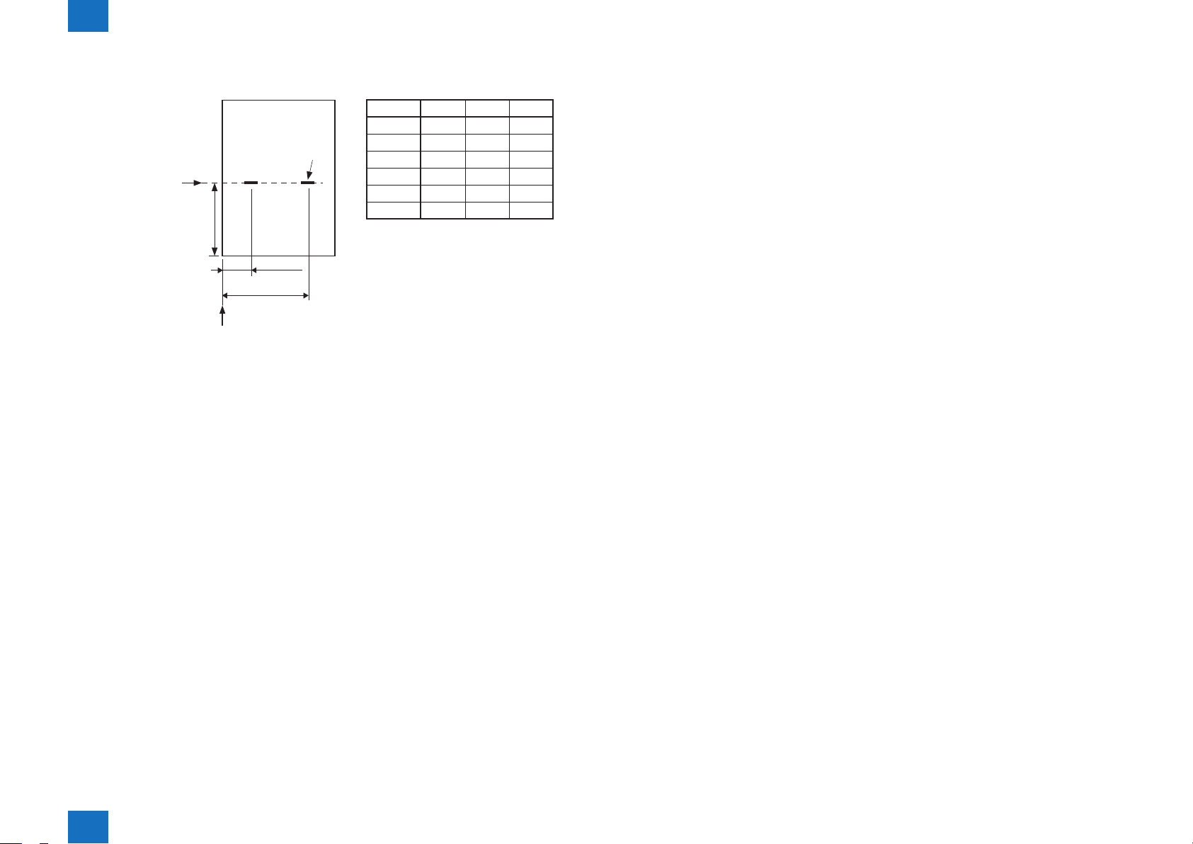
saddle stitcher
●
1-4
Folding position
Stample position
L3±1.0mm
L1±2.0mm
L2±2.0mm
Stack front edge
Paper Size
A3
B4
A4R
11"x17"
LGL
LTRR
L1
88.5
68.5
45
79.7
48
48
L2
208.5
188.5
165
199.7
168
168
L3
210
182
148.5
216
177.8
139.7
F-1-2
Product Outline > Product Specications > Specications > Staple Position
1
1-4
1
Product Outline > Names of Parts > External View
1-5
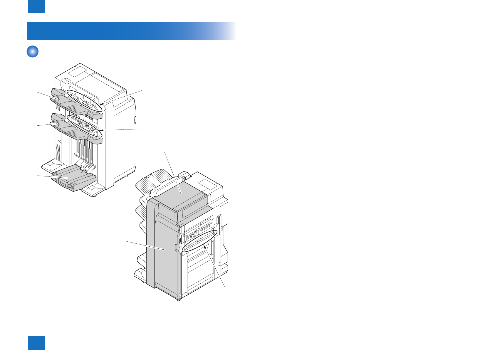
Names of Parts
External View
[2]
[1]
[5]
[1] Tray B [5] Saddle delivery belt
[2] Tray A [6] Upper cover
[3] Top delivery outlet [7] Inlet transport unit
[4] Bottom delivery outlet [8] Front cover
[3]
[4]
[6]
Product Outline > Names of Parts > External View
1
[8]
[7]
F-1-3
1-5

1
Product Outline > Names of Parts > Cross Section
Cross Section
1-6
[7] [8]
[6]
[5]
[4]
[3]
[2]
[1]
[31]
[9]
[11] [12][10] [13]
[14]
[15]
[16]
[17]
[18]
[19]
[20]
[21]
[22]
[1] Feed belt [17] Assist roller 1
[2] Sheaf eject roller [18] Inlet delivery roller
[3] Swing guide [19] Saddle inlet delivery roller
[4] Paddle [20] Stapler
[5] Tray B [21] Stitcher
[6] Process feed roller [22] Pull-out roller
[7] Tray A [23] Paper guide plate
[8] Eject roller [24] Fold delivery roller
[9] Buffer roller 2 [25] Adjust roller (upper)
[10] Assist roller 3 [26] Adjust roller (lower)
[11] Buffer roller 3 [27] Sheaf delivery roller
[12] Delivery roller [28] Pre-press roller
[13] Buffer roller 1 [29] Press unit
[14] Assist roller 2 [30] Saddle delivery belt
[15] Shift roller 2 [31] Waste staple case
[16] Shift roller 1
Product Outline > Names of Parts > Cross Section
1
[26]
[23]
[24]
[25][27][28][29][30]
F-1-4
1-6

Technology
2
Basic Construction
■
Electrical Control Unit
■
Stacking Unit
■
Feeding Unit
■
Intermediate Process Tray Assembly
■
Saddle Stitcher Unit
■
Detecting Jams
■
2
Technology
2
Technology > Basic Construction > Overview
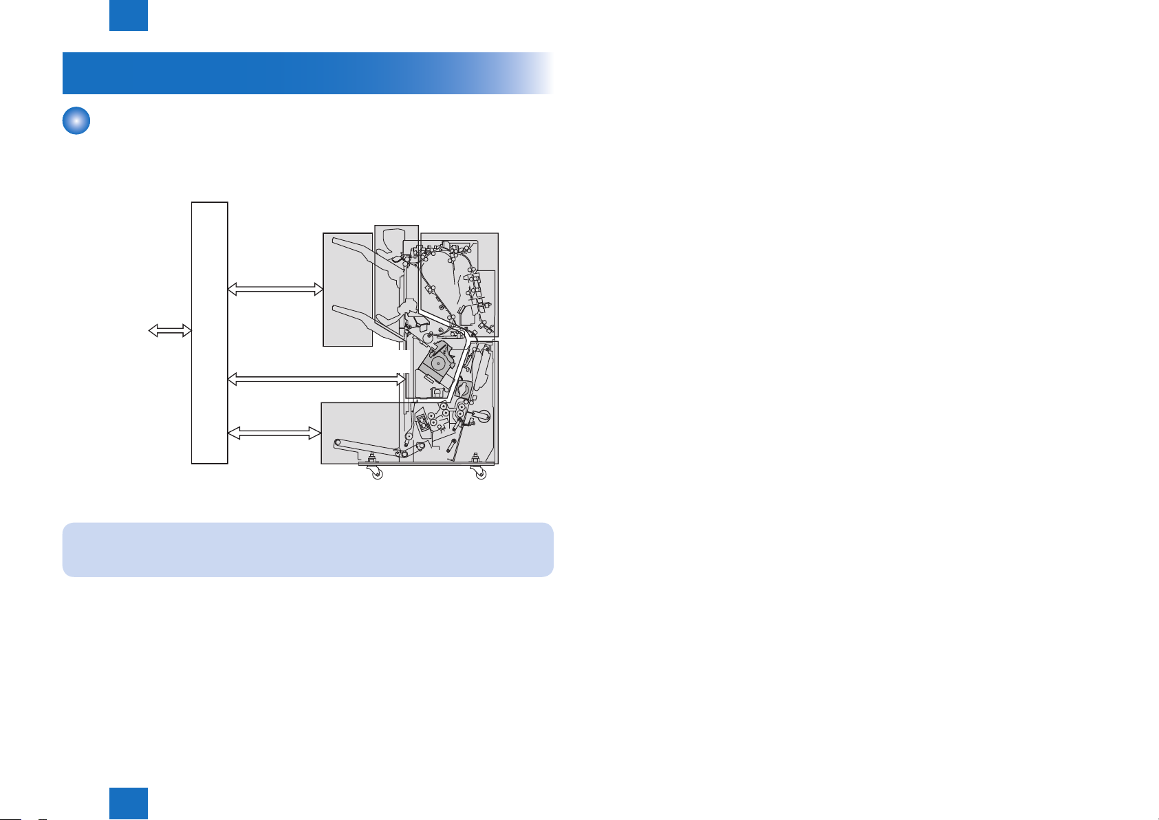
Basic Construction
Overview
The machine consists of the following 5 blocks: electrical control block, stacking block,
transport block, intermediary tray, and saddle stitcher block.
Electrical control block
Stacking block
To host machine
Intermediary
tray block
Saddle stitcher block
Transport
block
2-2
F-2-1
NOTE:
The descriptions on the saddle stitcher block apply to the Booklet Finisher-Q1 PRO.
Technology > Basic Construction > Overview
2
2-2
2
Technology > Electrical Control Unit > Finisher Controller PCB
2-3
Electrical Control Unit
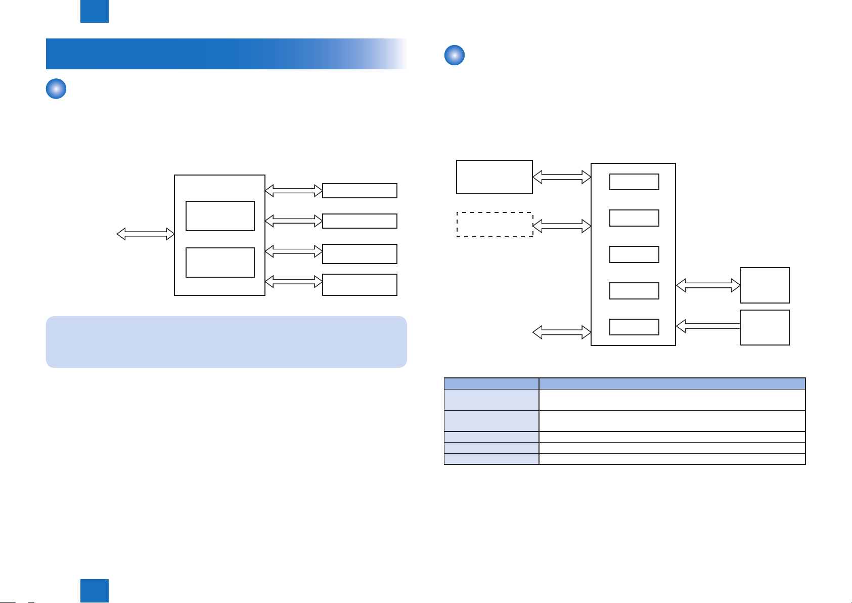
Overview
The electrical control block governs all the control mechanisms of the machine, i.e., stacking
block, transport block, intermediary tray block, and saddle stitcher block.
The electrical control block consists of 2 entities: nisher controller PCB and saddle stitcher
controller PCB.
Electrical
control block
Finisher
controller PCB
To host machine
Saddle stitcher
controller PCB
NOTE:
The descriptions on the saddle stitcher controller PCB apply to the Booklet Finisher-F1
PRO.
Stacking block
Transport block
Intermediary
tray block
Saddle stitcher
block
F-2-2
Finisher Controller PCB
The nisher controller PCB drives the various loads (motors, solenoids) of the machine in
response to the commands from the host machine (copier), and indicates the states of the
sensors and switches to the host machine.
It also serves to control the punch unit and the saddle nisher controller PCB.
Finisher
controller PCB
Saddle stitcher
controller PCB
Punch unit
(accessory)
To host machine
The machine uses the following ICs, each possessing specic functions:
IC Description
CPU Controls the communications with the host machine; controls ASIC1/
ASIC2.
ASIC1 Controls the communications with accessories; controls the drive to
various loads.
ASIC2 Controls the drive to various loads.
ROM Stores the rmware used to operate the machine.
EEPROM Stores counter readings and adjustment values.
CPU
ASIC1
ASIC2
ROM
EEPROM
Motor,
Solenoid
Switch,
Sensor
F-2-3
T-2-1
Technology > Electrical Control Unit > Finisher Controller PCB
2
2-3
2
Technology > Electrical Control Unit > Saddle Stitcher Controller PCB
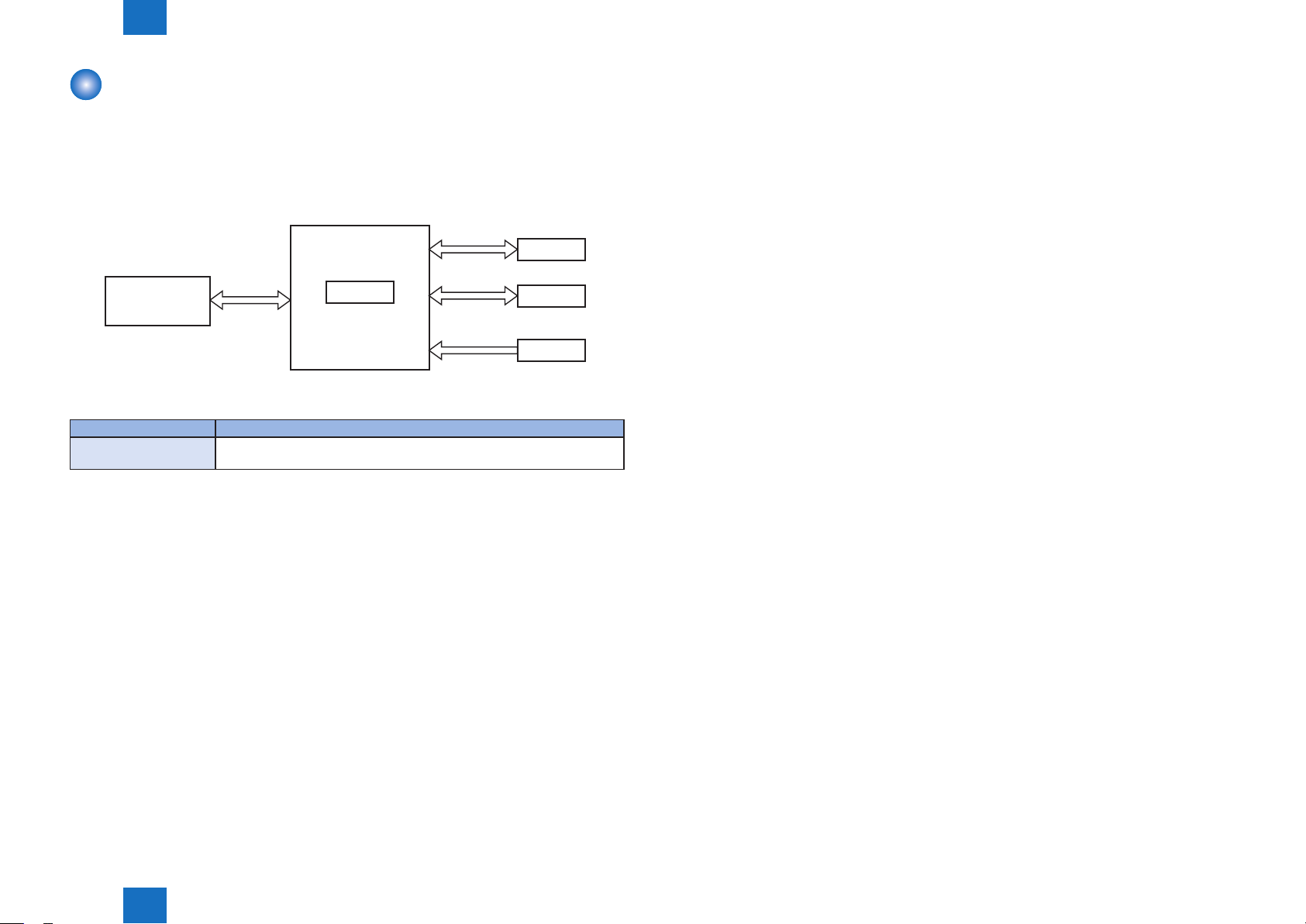
Saddle Stitcher Controller PCB
The saddle stitcher controller PCB drives the machine's various loads (motors, solenoids) in
response to the commands from the nisher controller, and indicates the states of sensors
and switches to the host machine.
Saddle stitcher
controller PCB
Motor
2-4
Finisher
Controller PCB
The machine uses the following major ICs possessing specic functions:
IC Description
ASIC1 Controls the communications with the nisher controller; controls the drive
to various loads.
ASIC1
Solenoid
Sensor
F-2-4
T-2-2
Technology > Electrical Control Unit > Saddle Stitcher Controller PCB
2
2-4
2
Technology > Stacking Unit > Overview
Stacking Unit
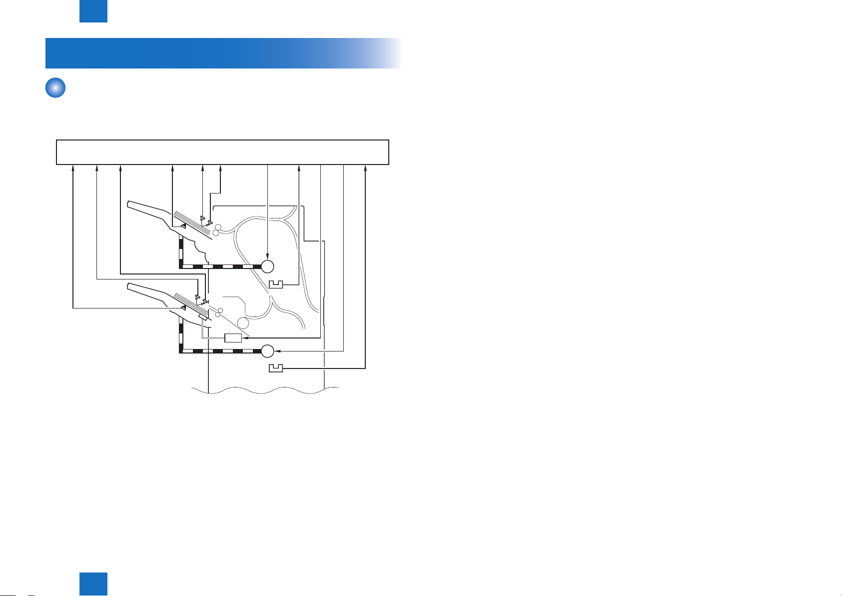
Overview
The stacking block moves up and down the 2 delivery trays according to the instructions from
the nisher controller PCB.
Finisher controller PCB
[1] [2] [3] [4] [5] [6] [7] [8] [9]
UN15
Tray A
PS32
UN16
[11][10]
[1] Tray B paper detection signal [7] Tray A lift motor drive single
[2] Tray B paper surface detection light-
emitting signal
[3] Tray B paper surface detection light-
receiving signal
[4] Tray A paper detection signal
[5] Tray A paper surface detection light-
emitting signal
[6] Tray A paper surface detection light-
receiving signal
[8] Tray A lift motor rotation detection
signal
[10] Tray B lift motor drive signal
[11] Tray B lift motor rotation detection
signal
2-5
Tray B
UN17
PS33
UN18
SL9
M22
M23
PS34
PS35
M22 : Tray A lift motor UN15 : Tray A paper side sensor board
(emitter)
M23 : Tray B lift motor UN16 : Train A paper side sensor board
(receiver)
PS32 : Tray A paper sensor UN17 : Tray B paper side sensor board
(emitter)
PS33 : Tray A paper sensor UN18 : Train B paper side sensor board
(receiver)
PS34 : Tray A lift motor rotation sensor
PS35 : Tray B lift motor rotation sensor
F-2-5
Technology > Stacking Unit > Overview
2
2-5
2
Technology > Stacking Unit > Tray Ascent/Descent Control
2-6
Tray Ascent/Descent Control
The tray A/B is moved up or down by controlling 2 motors (M22, M23) in response to the
instructions from the nisher controller.
The machine uses 2 sensors (PS34, PS35) to check for faults in these motors.
The sensor monitors the rotation of the motors; when any of the following occurs, the nisher
controller PCB will stop the drive to the motor and, at the same time, will communicate the
fact to the host machine:
Related Error Code
• E540 (fault in tray A)
While the tray A motor (M22) is rotating, the tray A lift motor rotation detection signal is
absent for 250 msec or more.
• E542 (fault in tray A)
While the tray B motor (M23) is rotating, the tray B lift motor rotation detection signal is
absent for 250 msec or more.
Finisher controller PCB
[1] [2] [3] [4]
Tray A
M22
PS34
Tray B
M23
PS35
[1] Tray A lift motor drive signal [3] Tray B lift motor drive signal
[2] Tray A lift motor rotation detection
signal
[4] Tray B lift motor rotation detection
signal
F-2-6
Technology > Stacking Unit > Tray Ascent/Descent Control
2
M22 : Tray A lift motor PS34 : Tray A lift motor rotation sensor
M23 : Tray B lift motor PS35 : Tray B lift motor rotation sensor
2-6
2
Technology > Stacking Unit > Auxiliary Tray Lift Control
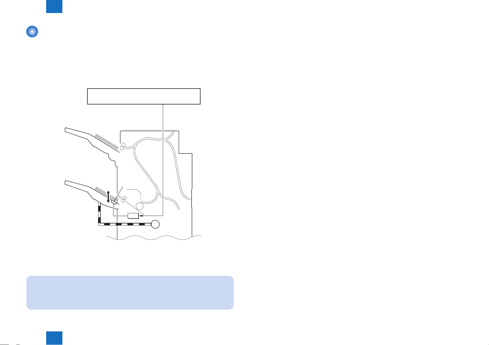
Auxiliary Tray Lift Control
In response to an increase in the number of folded sheets in the tray, the auxiliary tray is
moved up to prevent a delivery jam associated with the tray B (memo) by making sure that
the lead and trail edges of the stacks deposited in the tray will be even.
The auxiliary tray is moved by operating the solenoid (SL9) according to the instructions from
the nisher controller PCB.
Finisher controller PCB
[1]
Tray A
2-7
Auxiliary tray
Tray B
SL9
M23
F-2-7
[1] Auxiliary tray solenoid drive signal SL9 : Auxiliary tray solenoid
M23 : Tray lift motor
NOTE:
A stack with a folded sheet tends to be higher along its lead edge than its trail edge,
blocking the discharge slot when it contains multiple folded sheets. (A subsequent
sheet will likely hit the preceding sheet, causing a jam.)
Technology > Stacking Unit > Auxiliary Tray Lift Control
2
2-7
2
Technology > Stacking Unit > Tray Paper Surface Detection
2-8
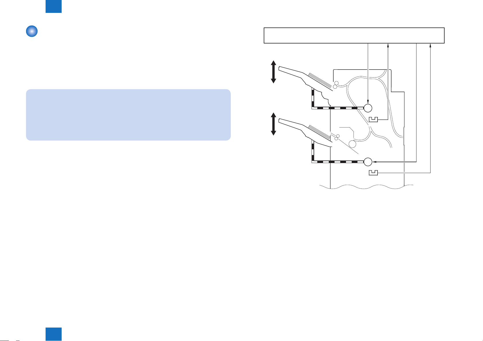
Tray Paper Surface Detection
The machine is equipped with a mechanism to detect the position of the top of the stack
deposited in its 2 trays.
The trays are each tted with a sensor PCB that consists of a light-emitting segment (UN15,
UN17) and a light-receiving segment (UN16, UN18).
The light-emitting segment is arranged at the rear of the machine, and is a LED. The lightreceiving segment, on the other hand, is found at the front of the machine, and it consists of 3
photosensors.
When the power is turned on or a jam has been removed, the nisher controller PCB checks
the 3 photosensors (light-receiving segment) as soon as the LED (lightemitting segment)
goes on.
As more and more sheets are deposited in the tray, the light reaching the light-receiving
segments will be blocked, causing the nisher controller PCB to move down the tray to keep
the top of the stack at a specic level.
When the tray becomes full of paper (i.e., light blocked, not reaching any of the 3
photosensors), the nisher controller PCB switches over to a different tray for subsequent
delivery. If the newly selected tray is full, it will stop the operation of the machine, and will
indicate the fact to the host machine.
UN15
[4]
[6]
[1]
UN16
[2]
UN17
[5]
[1]
UN18
[3]
[1]
[2]
[1]
[2]
UN16
UN16
[1] Paper [4] Non-sort delivery roller
[2] Tray A [5] Stack delivery roller
[3] Tray B [6] Tray descent movement (sample)
3
2
1
3
2
1
F-2-8
Technology > Stacking Unit > Tray Paper Surface Detection
2
UN15 : Tray A paper surface sensor
(light-emitting)
UN16 : Tray A paper surface sensor
(light-receiving)
UN17 : Tray B paper surface sensor
(light-emitting)
UN18 : Tray B paper surface sensor
(light-receiving)
2-8
2
Technology > Feeding Unit > Overview
2-9
Feeding Unit
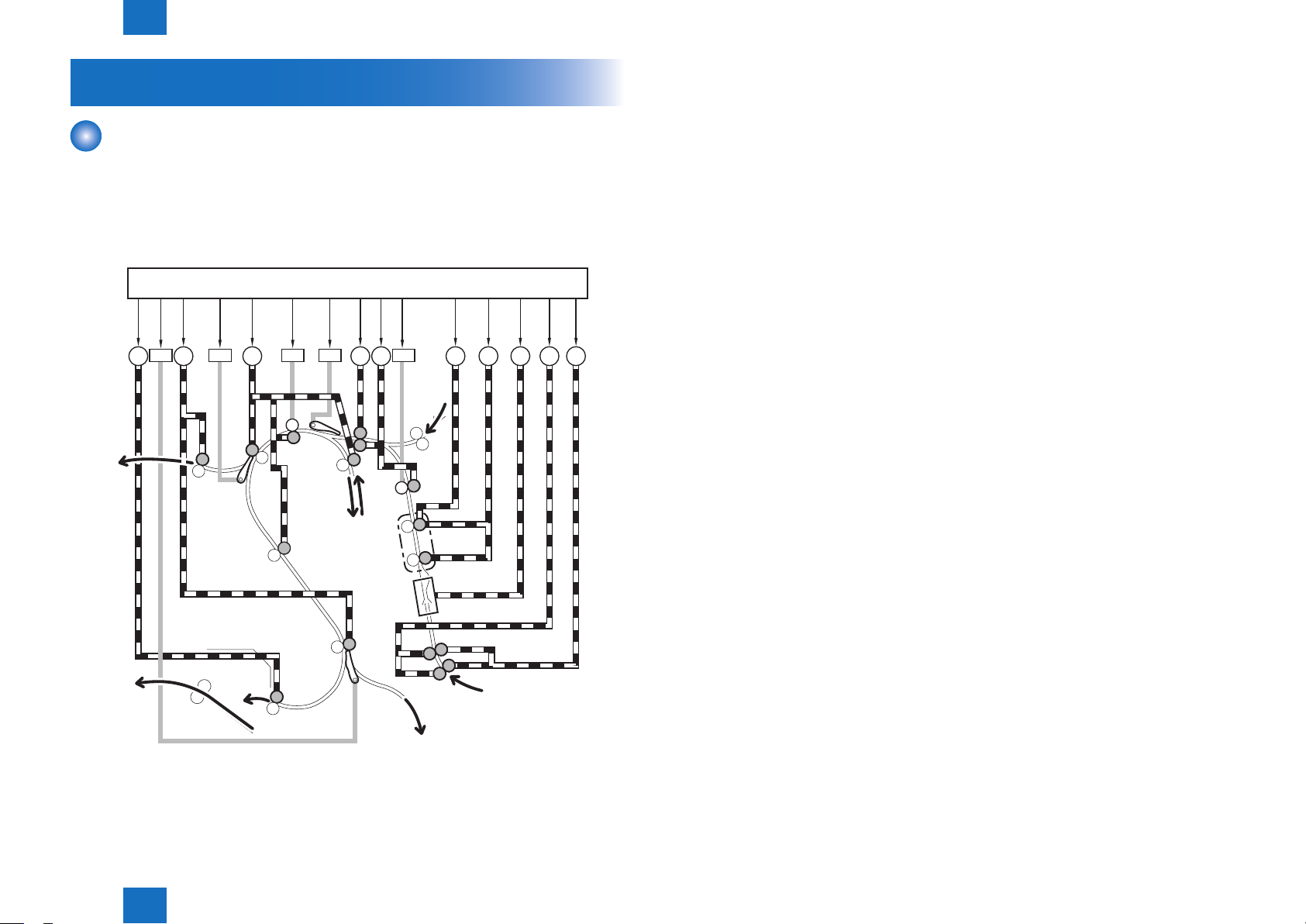
Overview
The machine's transport block serves to move paper to the stacking block or the saddle
stitcher block according to the instructions from the nisher controller PCB.
It also is used in conjunction with horizontal registration adjustment and alignment operation.
The machine uses 6 sensors to check for jams in the paper path.
Finisher Controller PCB
[1]
[2]
[3]
[4]
[5]
To tray A
[6] [7] [8] [9]
SL2SL3 SL1SL11
M4M5M26 M8 M7 M2
[10]
SL10
M3 M6 M27M1
inserter
From
[11]
[12]
[13]
[14]
[15]
[1] Process feed motor driver signal [9] Buffer front transport motor drive signal
[2] Saddle path switch solenoid drive
signal
[3] Delivery motor drive signal [11] Horizontal registration motor drive
[4] Upper path switch solenoid drive
signal
[5] Buffer motor drive signal [13] Horizontal registration detection unit
[6] Assist Motor Disengagement
Solenoid 2 drive signal
[7] Buffer path switch solenoid [15] Inlet roller disengage motor drive signal
[8] Transport roller shift motor drive
signal
M1 : Inlet transport motor M27 : Inlet motor separation motor
M2 : Shift transport motor SL1 : Buffer path switch solenoid
M3 : Buffer front transport motor SL2 : Upper path switch solenoid
M4 : Buffer motor SL3 : Saddle path switch solenoid
M5 : Delivery motor SL10 Assist Motor Disengagement Solenoid
M6 : Horizontal registration detection unit
shift motor
M7 : Horizontal registration shift motor
M8 : Transport roller shift motor
M26 : Operation feed motor
[10] Assist Motor Disengagement Solenoid
1 drive signal
signal
[12] Shift transport motor drive signal
shift motor drive signal
[14] Inlet transport motor drive signal
1
SL11 Assist Motor Disengagement Solenoid
2
To tray B
Technology > Feeding Unit > Overview
2
Shift Unit
Horizontal
Registration
Detection Unit
To saddle stitcher block
From host machine
F-2-9
2-9
2
Technology > Feeding Unit > Overview
Finisher controller PCB
2-10
[1] [3][2] [4] [5]
To tray A
To tray B
PS5
UN14
UN22
PS6
From inserter
UN13
PS4
To saddle stitcher unit
[6]
PS3
From host machine
[1] Lower delivery sensor signal [5] Buffer path 1 sensor signal
[2] Lower path sensor signal [6] Shift unit trailing edge sensor
[3] Upper delivery sensor signal
detection signal
[4] Buffer path 2 sensor signal [7] Inlet sensor signal
[7]
F-2-10
PS3 : Inlet sensor UN13 : Buffer path 1 sensor PCB
PS4 : Shift unit trailing edge sensor UN14 : Buffer path 2 sensor PCB
PS5 : Upper delivery sensor UN22 : Lower path sensor PCB
PS6 : Lower delivery sensor
Technology > Feeding Unit > Overview
2
2-10
2
Technology > Feeding Unit > Basic Sequence of Operations
2-11
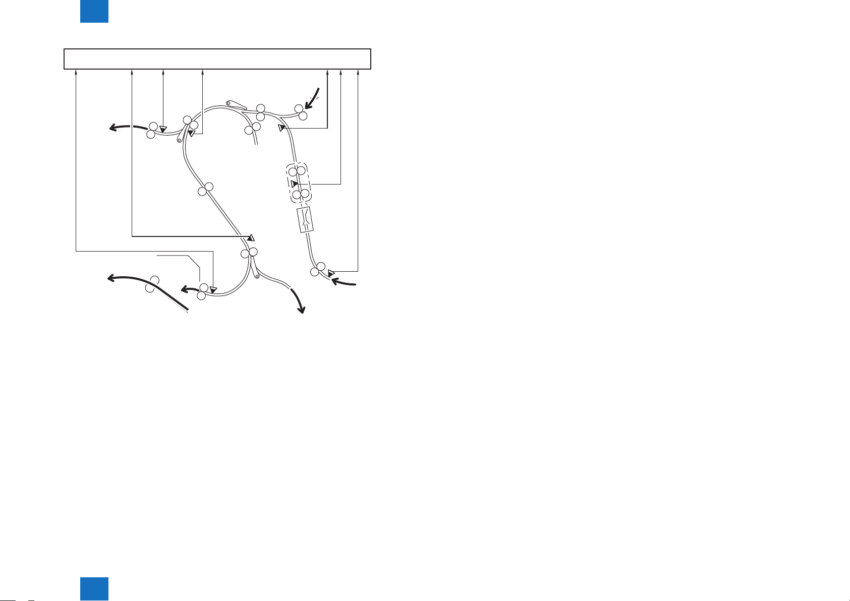
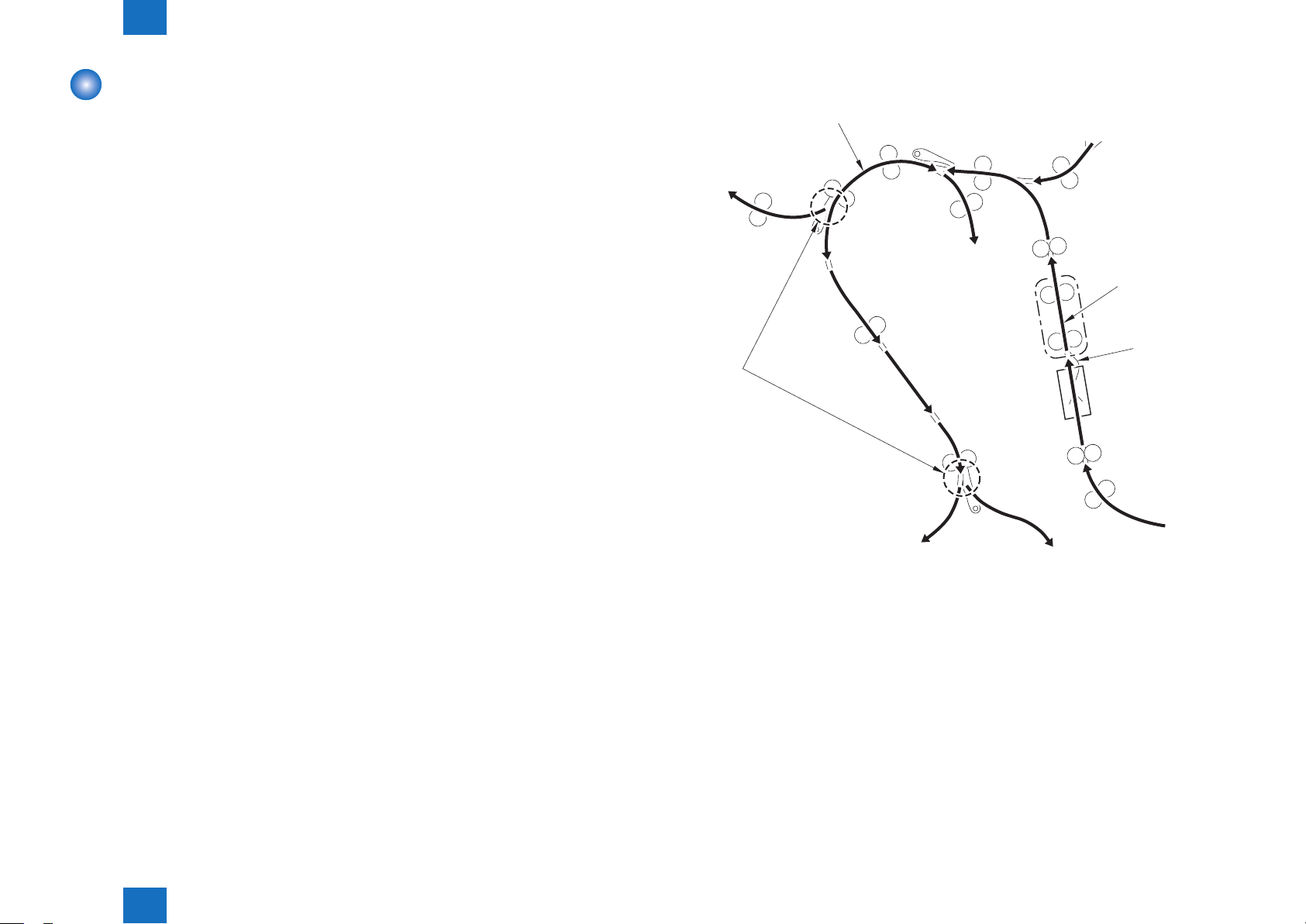
Basic Sequence of Operations
The transport block uses a sequence of operations that consists of the following 5:
1.HorizontalRegistrationDetection[1]
Detects the position of the paper.
2.HorizontalRegistrationCorrection[2]
Corrects the position of the paper with reference to the result of horizontal registration
detection.
3.Alignment[3]
Switches the position of the stack with reference to the result of horizontal registration
detection. (only in shift mode)
4.BufferOperation[4]
Keeps the sheet stationary inside the transport block; thereafter, joins it with the subsequent
sheet for forward movement.
5.MovementSwitch-Over[5]
Moves the paper to the stacking block or the saddle stitcher block.
6.
The particulars of individual operations are as follows:
[4]
To stacking block
[5]
From inserter
[2]
[3]
[1]
Technology > Feeding Unit > Basic Sequence of Operations
2
To stacking block
From host machine
To saddle stitcher block
F-2-11
2-11
 Loading...