

Canon Staple Finisher-AA1, BookletFinisher-AA1 Service Manual

Revision 4.0
Staple Finisher-AA1/Booklet
Finisher-AA1
Service Manual

1x
1x
Introduction
Introduction
Important Notices
Application
This manual has been issued by Canon Inc. for qualified persons to learn technical theory, installation, maintenance, and repair
of products.
This manual covers all localities where the products are sold. For this reason, there may be information in this manual that does
not apply to your locality.
Corrections
This manual may contain technical inaccuracies or typographical errors due to improvements or changes in products.
When changes occur in applicable products or in the contents of this manual, Canon will release technical information as the
need arises. In the event of major changes in the contents of this manual over a long or short period, Canon will issue a new
edition of this manual.
The following paragraph does not apply to any countries where such provisions are inconsistent with local law.
Trademarks
The product names and company names used in this manual are the registered trademarks of the individual companies.
Copyright
This manual is copyrighted with all rights reserved. Under the copyright laws, this manual may not be copied, reproduced or
translated into another language, in whole or in part, without the consent of Canon Inc.
Copyright CANON INC. 2016
Caution
Use of this manual should be strictly supervised to avoid disclosure of confidential information.
Explanation of Symbols
The following symbols are used throughout this Service Manual.
Symbols Explanation Symbols Explanation
Check.
Remove the claw.
Check visually.
Check a sound. Push the part.
Insert the claw.

1x
1x
1x
1x
1x
1x
1x
1x
Introduction
Symbols Explanation Symbols Explanation
Disconnect the connector. Connect the power cable.
Connect the connector. Disconnect the power cable.
Remove the cable/wire from the
cable guide or wire saddle.
Install the cable/wire to the cable
guide or wire saddle.
Remove the screw.
Install the screw.
Cleaning is needed. Measurement is needed.
The following rules apply throughout this Service Manual:
1. Each chapter contains sections explaining the purpose of specific functions and the relationship between electrical and
mechanical systems with reference to the timing of operation.
In the diagrams, represents the path of mechanical drive; where a signal name accompanies the symbol, the arrow
indicates the direction of the electric signal.
The expression "turn on the power" means flipping on the power switch, closing the front door, and closing the delivery unit
door, which results in supplying the machine with power.
2. In the digital circuits, '1' is used to indicate that the voltage level of a given signal is "High", while '0' is used to indicate "Low".
(The voltage value, however, differs from circuit to circuit.) In addition, the asterisk (*) as in "DRMD*" indicates that the DRMD
signal goes on when '0'.
In practically all cases, the internal mechanisms of a microprocessor cannot be checked in the field. Therefore, the operations
of the microprocessors used in the machines are not discussed: they are explained in terms of from sensors to the input of
the DC controller PCB and from the output of the DC controller PCB to the loads.
The descriptions in this Service Manual are subject to change without notice for product improvement or other purposes, and
major changes will be communicated in the form of Service Information bulletins.
All service persons are expected to have a good understanding of the contents of this Service Manual and all relevant Service
Information bulletins and be able to identify and isolate faults in the machine.
Turn on the power.
Turn off the power.
Loosen the screw.
Tighten the screw.

Contents
Contents
Safety Precautions...............................................................................................1
Notes Before Servicing........................................................................................................................2
Points to Note at Cleaning...................................................................................................................2
Notes On Assembly/Disassembly....................................................................................................... 2
Notes on Assembly/Disassembly........................................................................................................... 2
Points to Note when Tightening a Screw.................................................................................................2
1. Product Overview.............................................................................................4
Features.............................................................................................................................................. 5
Features...............................................................................................................................................5
Specifications...................................................................................................................................... 6
Finisher................................................................................................................................................ 6
Staple Unit............................................................................................................................................8
Staple-Free Binding Unit......................................................................................................................10
Saddle Stitcher Unit (Booklet Finisher)..................................................................................................11
Buffer Pass Unit..................................................................................................................................12
Others................................................................................................................................................ 13
Names of Parts..................................................................................................................................14
External View (Front)...........................................................................................................................14
External View (Rear)........................................................................................................................... 15
External View (Internal)....................................................................................................................... 17
Cross Section..................................................................................................................................... 18
Optional Configuration ......................................................................................................................20
2. Technical Explanation................................................................................... 21
Basic Configuration........................................................................................................................... 22
Component Configuration.................................................................................................................... 22
Overview of the Electrical Circuitry....................................................................................................... 23
Controls.............................................................................................................................................25
Controls..............................................................................................................................................25
Basic Operation.................................................................................................................................26
Outline............................................................................................................................................... 26
Feeding Unit......................................................................................................................................31
Outline............................................................................................................................................... 31
Basic Operation.................................................................................................................................. 32
Feed switch operation......................................................................................................................... 33
Shift Operation....................................................................................................................................34
Buffer Operation..................................................................................................................................37
Stack/Escape Tray Unit.....................................................................................................................40
Outline............................................................................................................................................... 40
Stack Tray Up and Down Movement.....................................................................................................41
Stack Tray Delivery Paper Surface Detection, Paper Full.......................................................................42
Escape Tray Paper Full Detection........................................................................................................ 45
Processing Tray Unit.........................................................................................................................46
i

Contents
Outline............................................................................................................................................... 46
Stacking Operation..............................................................................................................................47
Alignment/Shifting Operation................................................................................................................50
Staple Operation................................................................................................................................. 52
Staple-free Binding Operation.............................................................................................................. 55
Stack Delivery Operation..................................................................................................................... 58
Saddle Stitcher Unit...........................................................................................................................59
Outline ...............................................................................................................................................59
Configuration...................................................................................................................................... 60
Basic Operation.................................................................................................................................. 61
Stacking Operation..............................................................................................................................62
Paper Stack Feed Operation................................................................................................................64
Stitch Operation.................................................................................................................................. 65
Paper Folding/Delivery Operation.........................................................................................................65
Buffer Pass Unit................................................................................................................................ 67
Overview............................................................................................................................................ 67
Fan Operation.....................................................................................................................................67
Jam Detection................................................................................................................................... 69
Outline............................................................................................................................................... 69
Jams.................................................................................................................................................. 70
Power Supply.................................................................................................................................... 73
Power Supply Route............................................................................................................................73
Protection Function............................................................................................................................. 73
Upgrading .........................................................................................................................................74
3. Periodical Service.......................................................................................... 75
Periodic Servicing Tasks...................................................................................................................76
4. Parts Replacement and Cleaning................................................................. 77
Removing this Machine.....................................................................................................................78
Removing the Finisher.........................................................................................................................78
Removing the Buffer Pass Unit............................................................................................................ 78
List of Parts....................................................................................................................................... 80
External / Internal Covers ....................................................................................................................80
Main Units/Parts..................................................................................................................................81
List of Clutches................................................................................................................................... 84
List of Motors...................................................................................................................................... 84
List of Sensors....................................................................................................................................87
List of Switches/ Fans..........................................................................................................................89
List of PCBs........................................................................................................................................91
Other Parts.........................................................................................................................................93
External/Internal Covers....................................................................................................................94
Removing the Rear Cover....................................................................................................................94
Removing the Front Cover...................................................................................................................94
Removing the Lower Front Cover.........................................................................................................94
Removing the Front Inner Cover.......................................................................................................... 95
Main Parts......................................................................................................................................... 96
Removing the Escape Tray..................................................................................................................96
Removing the Stack Tray.....................................................................................................................96
ii

Contents
Removing the Grate-Shaped Lower Guide............................................................................................96
Removing the Swing Unit.....................................................................................................................97
Removing the Processing Tray...........................................................................................................102
Removing the Staple Drive Unit..........................................................................................................103
Removing the Saddle Delivery Tray....................................................................................................104
Removing the Saddle Unit................................................................................................................. 105
Removing the Pushing Unit................................................................................................................106
Removing the Buffer Pass Upper Unit.................................................................................................107
Removing the Static Eliminator (Upper/Lower Escape Delivery Unit).....................................................108
Removing the Stapler Unit................................................................................................................. 108
Removing the Saddle Stitcher Unit..................................................................................................... 109
Removing the Staple-Free Binding Unit.............................................................................................. 109
Removing the Static Eliminator (Stack tray Unit)..................................................................................112
Removing the Static Eliminator (Saddle Delivery Unit)......................................................................... 112
Removing the Paddle Unit................................................................................................................. 113
Removing the Lower Stack Delivery Roller Clutch (CL102).................................................................. 114
Removing the Escape Feed Clutch (CL101)........................................................................................114
Removing the Stack Tray Torque Limiter............................................................................................ 115
PCB.................................................................................................................................................116
Removing the Finisher Controller PCB (PCB101)................................................................................ 116
Removing the Saddle Stitcher Controller PCB (PCB201)..................................................................... 118
Removing the Buffer Pass Controller PCB (PCB201)...........................................................................118
Removing the Buffer Pass Power Supply PCB (PCB203).....................................................................119
Sensor.............................................................................................................................................121
Removing the Delivery Sensor (PS102).............................................................................................. 121
Clutch/ Solenoid.............................................................................................................................. 122
Removing the Paddle Clutch (CL103).................................................................................................122
Motors............................................................................................................................................. 123
Removing the Front Alignment Motor (M107)...................................................................................... 123
Removing the Rear Alignment Motor (M108).......................................................................................123
Removing the Tray Auxiliary Guide Motor (M109)................................................................................124
Removing the Paper End Assist Motor (M113).................................................................................... 124
Removing the Stapler Shift Motor (M114)............................................................................................125
Removing the Staple-Free Binding Motor (M116)................................................................................ 126
Removing the Saddle Paper Pushing Plate/Folding Motor (M204)........................................................ 127
Removing the Saddle Delivery Motor (M207)...................................................................................... 128
Switches .........................................................................................................................................129
Removing the Front Cover Switch (SW101)........................................................................................ 129
Removing the Swing Guide Safety Switch (SW102).............................................................................129
Removing the Manual Staple Switch (SW103).....................................................................................130
Other Parts .....................................................................................................................................131
Pulling Out the Saddle Unit (Service Position)..................................................................................... 131
Removing the Grate-shaped Guide.....................................................................................................131
Removing the Escape Delivery Roller.................................................................................................131
Removing the Return Roller............................................................................................................... 134
Removing the Swing Roller................................................................................................................135
Removing the Folding Roller.............................................................................................................. 136
Removing the pushing plate...............................................................................................................141
iii

Contents
5. Adjustment................................................................................................... 142
Overview......................................................................................................................................... 143
Service Mode....................................................................................................................................143
Basic Adjustment Items..................................................................................................................... 146
Adjustments When Replacing Parts Items...........................................................................................147
Other................................................................................................................................................147
Basic Adjustment.............................................................................................................................148
Overview.......................................................................................................................................... 148
Adjusting the Paper Alignment........................................................................................................... 149
Adjusting the Staple Position..............................................................................................................158
Adjusting the Fold Position ................................................................................................................162
Adjusting the Saddle Stitch ............................................................................................................... 167
Adjustments When Replacing Parts................................................................................................173
Phase Alignment When Installing the Stack Tray Drive Belt................................................................. 173
Phase Alignment When Installing the Swing Unit.................................................................................173
Phase adjustment of paddle unit.........................................................................................................174
Phase Alignment When Installing the Paper Folding Roller.................................................................. 179
Handling Finisher Controller PCB Replacements.................................................................................180
Other............................................................................................................................................... 184
Releasing the Saddle Delivery Tray Stacking Limit.............................................................................. 184
6. Troubleshooting...........................................................................................185
Making Initial Checks...................................................................................................................... 186
List of Initial Check Items................................................................................................................... 186
Processing Tray Area......................................................................................................................187
Adjusting the Alignment and the Staple Position..................................................................................187
Saddle Stitcher Area....................................................................................................................... 188
Fold Placement / Saddle Stitch Adjustment......................................................................................... 188
7. Installation.................................................................................................... 189
How to Utilize This Installation Procedure.......................................................................................190
Illustrations Used in This Procedure....................................................................................................190
Product Name...................................................................................................................................190
Checking Before Installation............................................................................................................191
Checking the Installation Space..........................................................................................................191
Checking the Unpacking Space..........................................................................................................192
Check Items When Turning OFF the Main Power................................................................................ 192
Points to Note on Installation..............................................................................................................193
Installing the Accessories...................................................................................................................194
Unpacking....................................................................................................................................... 195
Unpacking Procedure........................................................................................................................ 195
Checking the Contents....................................................................................................................198
Installation Procedure......................................................................................................................199
Preparing the Host Machine for Installation......................................................................................... 199
Installation of Buffer Pass Unit............................................................................................................202
Preparing The Finisher for Installation.................................................................................................205
Connecting to Host Machine.............................................................................................................. 205
Affixing the Labels...........................................................................................................................208
iv

Contents
Jam Label / Saddle Caution Language Label (Booklet Finisher only).................................................... 208
Tray Setting Labels........................................................................................................................... 208
Making Adjustments........................................................................................................................209
Making Check and Adjustment of the Height....................................................................................... 209
Making Check and Adjustment of the Tilt............................................................................................ 210
Making Checks After Completion of Adjustments.................................................................................212
Making Checks After Completion of Installation Work.................................................................... 213
Disposal Parts Check........................................................................................................................ 213
Operation Check............................................................................................................................... 213
Detaching from the Host Machine...................................................................................................214
Finisher............................................................................................................................................ 214
Buffer Pass Unit................................................................................................................................ 214
APPENDICES....................................................................................................216
Service Tools...................................................................................................................................217
Solvents and Oils.............................................................................................................................. 217
Special Tools.................................................................................................................................... 217
General Circuit Diagram..................................................................................................................218
General Circuit Diagram 1/3...............................................................................................................218
General Circuit Diagram 2/3...............................................................................................................219
General Circuit Diagram 3/3...............................................................................................................220
v

Safety Precautions
Notes Before Servicing......................... 2
Points to Note at Cleaning.................... 2
Notes On Assembly/Disassembly.........2
Safety Precautions
Notes Before Servicing
CAUTION:
At servicing, be sure to turn off the power source according to the specified steps and disconnect the power plug.
CAUTION:
Do not turn off the power switch when downloading is under way. Turning off the main power switch while downloading is
under way can disable the machine.
Points to Note at Cleaning
CAUTION:
When performing cleaning using organic solvent such as alcohol, be sure to check that the component of solvent is
vaporized completely before assembling.
Notes On Assembly/Disassembly
Notes on Assembly/Disassembly
Follow the items below to assemble/disassemble the device.
1. Disconnect the power plug to avoid any potential dangers during assembling/disassembling works.
2. If not specially instructed, reverse the order of disassembly to reinstall.
3. Ensure to use the right screw type (length, diameter, etc.) at the right position when assembling.
4. To keep electric conduction, binding screws with washers are used to attach the grounding wire and the varistor. Ensure to
use the right screw type when assembling.
5. Unless it is specially needed, do not operate the device with some parts removed.
6. Never remove the paint-locked screws when disassembling.
7. During disassembly, reassembly or transportation of the printer, remove the cartridge if required. When the cartridge is out
of the printer, put it in a protective bag even in a short period of time to prevent the adverse effect of light.
8. When you replace the part that the rating plate or the product code label is attached, be sure to remove the rating plate or
the product code label and put it to the new part.
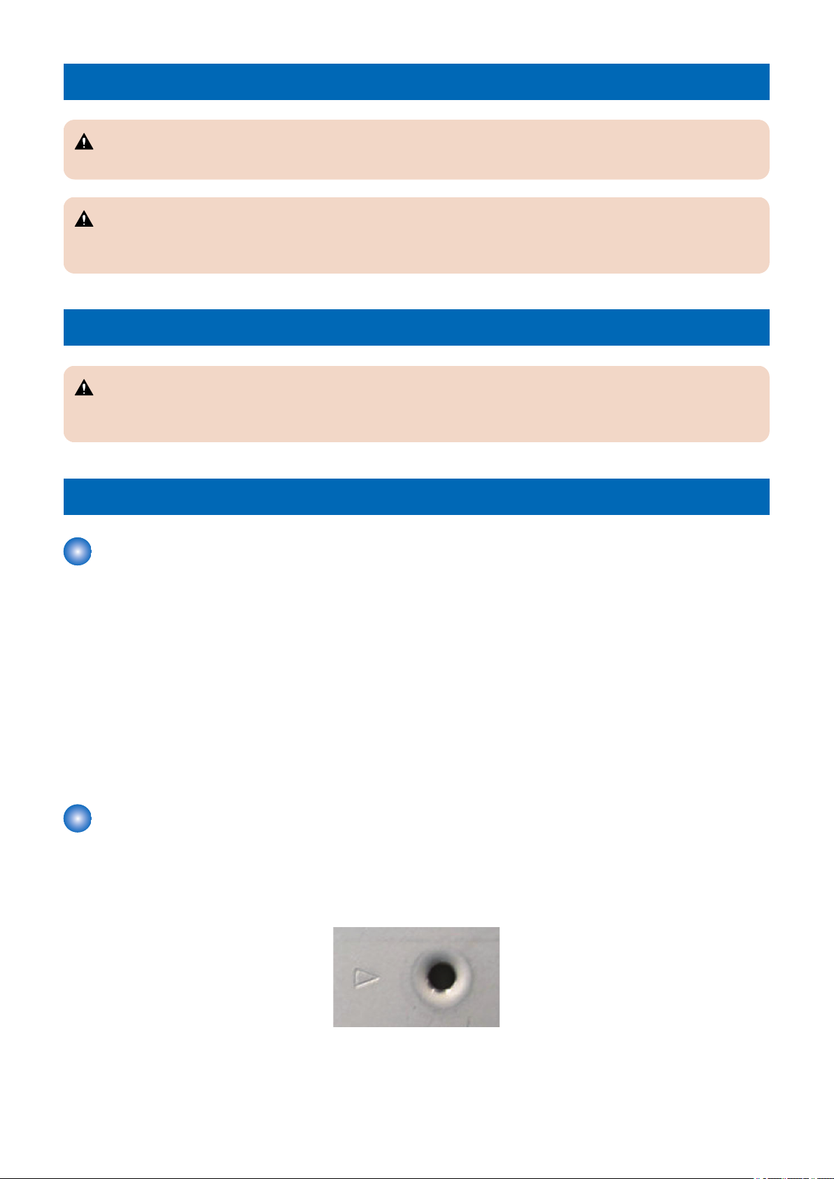
Points to Note when Tightening a Screw
For reduction in weight, thin plates are used in some parts of this machine.
In the case of a screw hole with a triangle mark near it as shown in the figure below, strongly tightening the screw may damage
or deform the screw hole.
In the case of a screw hole with a triangle mark, take care not to apply too much force when tightening the screw.
2
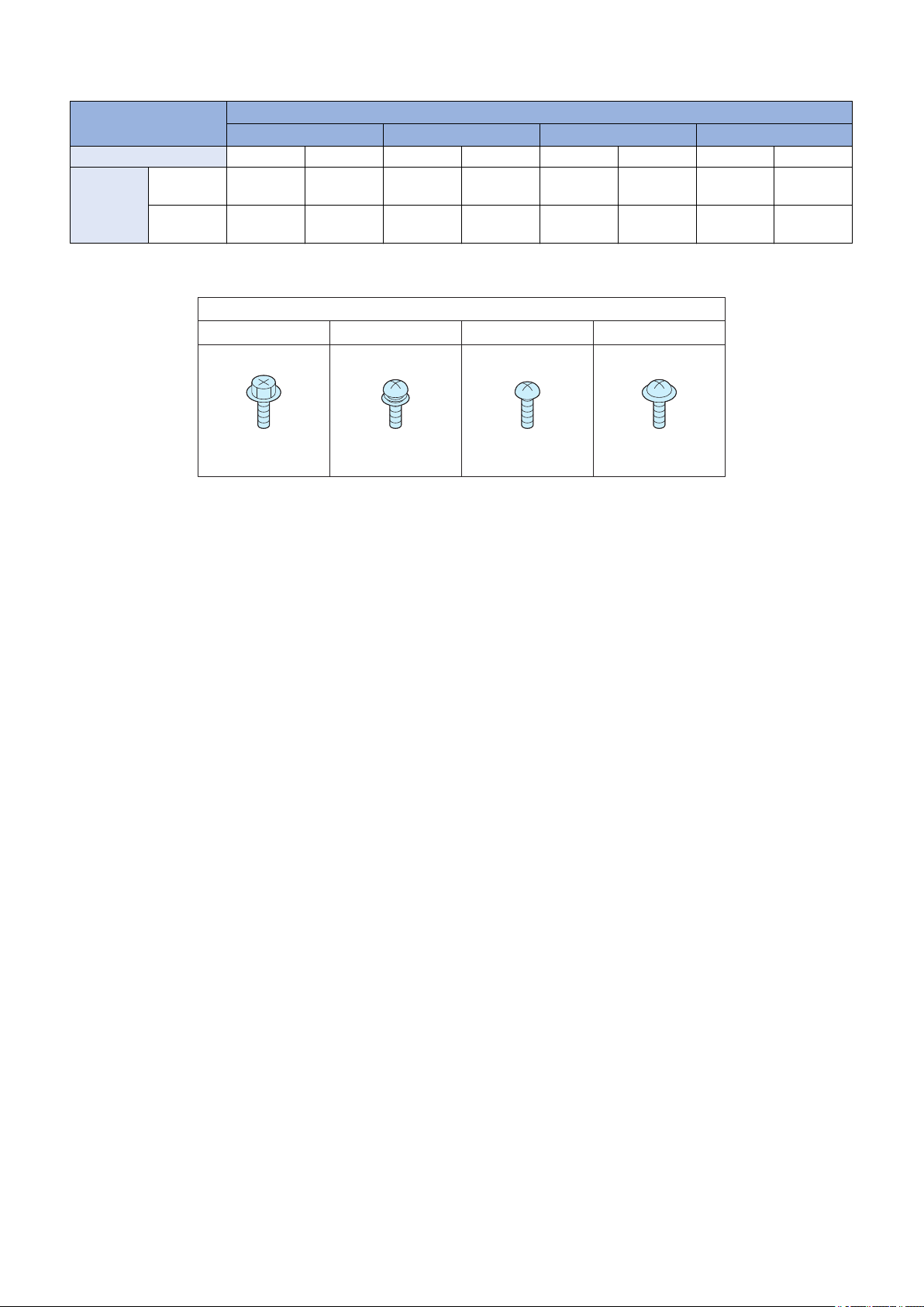
RS tight
Type of Screws
W Sems Binding TP
Safety Precautions
The recommended torque value is shown below as a reference value.
Type of Screws
RS tight W Sems Binding TP
Fastened member Metal Resin Metal Resin Metal Resin Metal Resin
Tightening
torque
(N*m)
* For PCB, refer to the tightening torque value of resin (fastened member).
M4 Approx.
1.6
M3 Approx.
0.8
Approx.
1.6
Approx.
0.8
Approx.
1.6
Approx.
0.6
Approx.
0.8
Approx.
0.6
Approx.
1.6
Approx.
0.6
Approx.
0.8
Approx.
0.6
Approx.
1.6
Approx.
0.6
Approx.
0.8
Approx.
0.6
3

1
Product Overview
Features................................................5
Specifications........................................6
Names of Parts................................... 14
Optional Configuration ....................... 20

1. Product Overview
Features
Features
• The main unit size has been reduced to allow installation in smaller space.
• The optional puncher unit can be installed in the finisher.
• Paper shift mechanism is incorporated into the escape tray delivery area allowing the shift sort stacking in the stack tray and
the upper/lower escape trays.
• Staple, manual staple, and staple-free binding functions are integrated allowing versatile stapling that suit the various
demands.
• Basic performance is substantial. That is the high-capacity stacking function that can stack up to 3,250 sheets (escape tray:
250 sheets, stack tray: 3,000 sheets), the staple function that can staple up to 50 sheets, and booklet binding function that
can stitch up to 20 sheets.
5

1. Product Overview
Specifications
Finisher
Item Specifications Remarks
Stacking method Stack tray: up and down moving type
Escape tray: fixed tray
Stacking orientation
Paper size Feed direction: 139.7 to 457.2 mm
Alignment stacking
size
Paper weight Escape tray 52 to 256 g/m2
Modes Non sort mode [Escape tray/stack tray]
Stacking capacity
(without folding
sheets)
Face up , face down
Cross feed direction: 98.0 to 320.0 mm
Feed direction: 182.0 to 432.0 mm
Cross feed direction: 210.0 to 297.0 mm
Stack tray [Non sort mode]
52 to 300 g/m2
[Shift sort mode/staple mode]
52 to 256 g/m2
[Staple-free binding mode]
52 to 105 g/m2
Feed direction: 139.7 to 457.2 mm
Cross feed direction: 98.0 to 320.0 mm
A3, A4, A4R, A5, A5R, B4, B5, B5R, 11×17, LGL, LTR, LTRR,
STMT, STMTR, EXEC, SRA3, 12"×18", 8K, 16K, 16KR
Shift sort mode [Escape tray]
A3, A4, B4, B5, 11×17, LTR, EXEC, 8K, 16K
[Stack tray]
A3, A4, A4R, B4, B5, 11×17, LGL, LTR, LTRR, EXEC, 8K, 16K
Staple mode [Stack tray]
A3, A4, 11×17, LGL, LTR, LTRR, EXEC, 8K, 16K
Staple-free binding
mode
Processing tray Feed length: 182 mm to 215.9 mm (50 sheets or less)
Escape tray Small size: Height 47 mm ± 3 mm or less (equivalent to 250
[Stack tray]
A3, A4, 11×17, LTR, 8K, 16K
Feed length: More than 215.9 mm to 431.8 mm (30 sheets or
less)
sheets)
Large size: Height 24 mm ± 3 mm or less (equivalent to 125
sheets)
- The stacking capacities are estimates when
converting weight to
number of 81.4 g/m2
sheets.
- The stacking capacities are estimates when
converting weight to
number of 81.4 g/m2
sheets.
- Alignment accuracy
and stacking capacity
for paper weighing 59 g/
m2 or less are not
specified.
6

1. Product Overview
Item Specifications Remarks
Stacking capacity
(without folding
sheets)
Mixed stacking capacity (without
folding sheets)
Stack tray [Non sort/shift sort mode]
- Plain paper
Small size: Height 423 mm or less (equivalent to 3,000 sheets)
(when saddle is used: Height 216 mm or less (equivalent to
1,500 sheets))
Large size: Height 216 mm or less (equivalent to 1,500 sheets)
- Coated paper
Small size: Height 216 mm or less (equivalent to 1,500 sheets)
Large size: Height 108 mm or less (equivalent to 750 sheets)
[Staple mode/staple-free binding mode]
- Plain paper
Small size: Height 423 mm or less, or 200 sets or less (when
saddle is used: Height 216 mm or less)
Large size: Height 216 mm or less, or 100 sets or less
- Coated paper
Small size: Height 216 mm or less, or 100 sets or less
Large size: Height 108 mm or less, or 50 sets or less
Escape tray [Mixed size]
Plain paper combination of A4, B5, and LTR only: Height 47 mm
± 3 mm or less
Combinations of other paper sizes: Height 24 mm ± 3 mm or less
Stack tray [Size mixing]
Plain paper combination of A4, B5, and LTR only : Height
216mm±3mm
Combinations of other paper sizes: Height 108mm ± 3mm
[Stapling mixing]
- Plain paper
Small size: Height 423 mm -/+ 3 mm or less, or 200 sets or less
Large size: Height 216 mm ± 3 mm or less, or 100 sets or less
- Coated paper
Small size: Height 216 mm ± 3 mm or less, or 100 sets or less
Large size: Height 108 mm ± 3mm or less, or 50 sets or less
[Mode mixing]
Plain paper combination of A4, B5, and LTR only: Height 423
mm ± 3 mm
Combinations of other paper sizes: Height 216 mm ± 3 mm or
less
- The stacking capacities are estimates when
converting weight to
number of 81.4 g/m2
sheets.
- The stacking capacity
for paper weighing 59 g/
m2 or less is for up to
the large size height,
and the alignment accuracy for 2-sided print
is not specified.
- Transparency, post
card, label and tracing
paper: 10 sheets or less
- Large size condition is
applied after a sheet of
paper of large size is
delivered.
- The stacking capacities are estimates when
converting weight to
number of 81.4 g/m2
sheets.
- The stacking capacity
for paper weighing 59 g/
m2 or less is for up to
the large size height
- The stacking capacities are estimates when
converting weight to
number of 81.4 g/m2
sheets.
- Stacking capacity is
not guaranteed.
- When the plain paper
and coated paper are
stacked, follows the
specifications of the
coated paper.
- The mixed stacking of
the small size paper
and 432 mm or more
length paper is not possible.
- Stacking on upper/
lower escape tray is not
possible for stapling
mixing and mode mixing.
- Paper size regulations:
Small size (feed length: 220 mm or less): A4, B5, LTR, EXEC, 16K, STMTR, A5R
Large size (feed length: more than 220 mm): A3, A4R, B4, B5R, 11 × 17, LGL, LTRR, 8K
7

1. Product Overview
Staple Unit
Item Specifications Remarks
Stapling method Punching by rotating cam Flat clinch
Stapling paper size Feed direction: 182 mm to 431.8 mm
Cross feed direction: 210 mm to 297 mm
1-point stapling, 2-points stapling
A3, A4, A4R, B4, B5, 11 × 17, LGL, LTR, LTRR, EXEC, 8K, 16K
Stapling capacity Paper Small size Large size - Paper thickness
52 to 90 g/m2 50 sheets 30 sheets
More than 90 to 105 g/m230 sheets 20 sheets
More than 105 to 300
g/m2
Manual stapling Paper thickness: 6.5mm or less (Equivalent to 50 sheets or less, 1-point stapling) - Converting weight to
Staple supply Special staple cartridge (5,000 staples)
Staple detection Available
Initial feed of staple Available
2 sheets 2 sheets
(small size): 11 mm or
less
- Paper thickness
(large size): 5.5 mm or
less
number of 64 g/m2
sheet.
- Paper size regulations:
Small size (feed length: 220 mm or less): A4, B5, LTR, EXEC, 16K , STMTR, A5R
Large size (feed length: more than 220 mm): A3, A4R, B4, B5R, 11 × 17, LGL, LTRR, 8K
8

• Staple Position
5.0 ± 2.0 mm
5.0 ± 2.0 mm
4.0 ± 2.0 mm
5.0 ± 2.0 mm
5.0 ± 2.0 mm
5.0 ± 2.0 mm
4.0 ± 2.0 mm
5.0 ± 2.0 mm
- Front 1-point stapling (45 deg): A3, A4, B4, B5, 11×17, LTR, EXEC, 8K, 16 K
- Front 1-point stapling (30 deg): A4R, LGL, LTRR
1. Product Overview
- Rear 1-point stapling (45 deg): A3, A4, B4, B5, 11×17, LTR, EXEC, 8K, 16K
- Rear 1-point stapling (30 deg): A4R, LGL, LTRR
9
L3
L1
L2
5.0 ± 2.0 mm
5.0 ± 2.0 mm
1. Product Overview
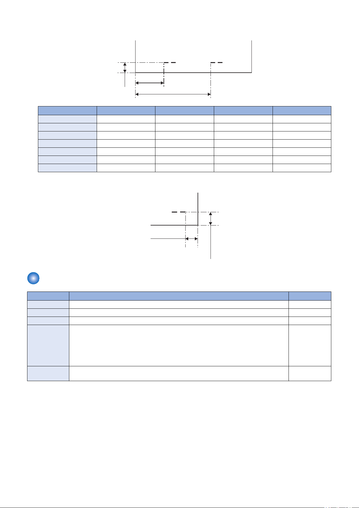
- 2-point stapling : A3, A4, A4R, B4, B5, 11×17, LGL, LTR, LTRR, EXEC, 8K, 16K
Paper Size L1 L2 L3 Interval
A3, A4 83 ± 4.0 mm 203 ± 4.0 mm 5.0 ± 2.0 mm 120 mm
B4, B5 63 ± 4.0 mm 183 ± 4.0 mm 5.0 ± 2.0 mm 120 mm
11×17, LTR 74.2 ± 4.0 mm 194.2 ± 4.0 mm 5.0 ± 2.0 mm 120 mm
A4R 39.5 ± 4.0 mm 159.5 ± 4.0 mm 5.0 ± 2.0 mm 120 mm
LTRR, LGL 42.5 ± 4.0 mm 162.5 ± 4.0 mm 5.0 ± 2.0 mm 120 mm
EXEC 68 ± 4.0 mm 188 ± 4.0 mm 5.0 ± 2.0 mm 120 mm
8K, 16K 69.5 ± 4.0 mm 189.5 ± 4.0 mm 5.0 ± 2.0 mm 120 mm
- Manual stapling
Staple-Free Binding Unit
Item Specifications Remarks
Binding method Pressing by rotating cam
Binding position Rear 1-point binding Tooth-shaped
Bindable size A3, A4, 11 × 17, LTR, 8K, 16 K
Binding capacity - 52 to 64 g/m2: 5 sheets or less
- More than 64 to 81.4 g/m2 : 4 sheets or less
- More than 81.4 to 105 g/m2 : 3 sheets or less
Manual staplefree binding
Not available
- Binding a mix of
different widths is
not possible.
- Binding a mix of
same width is
possible.
10
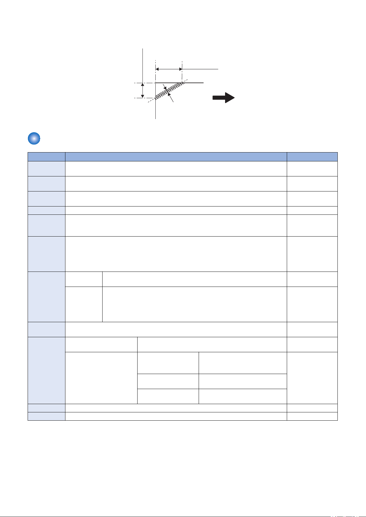
7.8 ± 2.0 mm
13.5 ± 2.0 mm
3.0 mm or less
Delivery direction
1. Product Overview
• Binding position
- Rear 1-point binding (30 deg)
Saddle Stitcher Unit (Booklet Finisher)
Item Specifications Remarks
Stacking orientation
Stapling meth-odVertically separated, semi-flat clinch, stapling at two positions in the middle
Fixed folding stack tray
Folding meth-odRoller pressure 2-fold
Fold position Center folding
Fold position Feed direction: 270 to 457.2 mm
Cross feed direction: 195 to 304.8 mm
A3, B4, A4R, 12X18, 11X17, LGL, LTRR
Paper weight Body page: 52 to 220 g/m2
Cover page: 52 to 256 g/m2
Capacity Without stitch - 52 to 105 g/m2: 1 to 3 sheets
- More than 105 to 256 g/m2: 1 sheet
With stitch - 52 to 81.4 g/m2: 2 to 20 sheets
- More than 81.4 to 105 g/m2: 2 to 10 sheets
- More than 105 to 150 g/m2: 2 to 5 sheets
- More than 150 to 209 g/m2: 2 to 4 sheets
- More than 209 to 220 g/m2: 2 or 3 sheets
Stackable paper
Stacking capacity
Staple supply Special staple cartridge (2,000 staples)
Staple supply Available
Thin, plain, recycled, environmental, heavy, coated paper
Without stitch - 52 to 105 g/m2: 25 sets
- More than 105 to 256 g/m2: 10 sets
With stitch, without cover 52 to 81.4 g/m2 2 to 5 sheets: 25 sets
6 to 10 sheets: 15 sets
11 to 20 sheets: 10 sets
More than 81.4 to 105
g/m2
More than 105 to 220
g/m2
2 to 5 sheets: 25 sets
6 to 10 sheets: 15 sets
10 sets
- Paper weight of the
cover page should
be more than paper
weight of the body
page.
- Includes one cover
page.
- With cover, up to 10
sets.
11
• Staple Position
L2 ± 2.0 mm
L3 ± 1.0 mm
L1 ± 2.0 mm
Stapling position
Feed direction
1.0 mm or less
Folding position
1. Product Overview
Paper Size L1 L2 L3
12"×18" 86.9 mm 206.9 mm 228.6 mm
A3 83 mm 203 mm 210 mm
B4 63 mm 183 mm 182 mm
A4R 39.5 mm 159.5 mm 148.5 mm
11×17 74.2 mm 194.2 mm 215.9 mm
LGL 42.5 mm 162.5 mm 177.8 mm
LTRR 42.5 mm 162.5 mm 139.7 mm
Buffer Pass Unit
Item Description Remarks
Placement Center
Installation Build-in type
Stacking size (Buffer
pass delivery tray)
Stacking capacity
(Buffer pass delivery
tray)
Dimensions W: 480mm × D: 485mm × H: 155mm
Weight Approx 5.4 kg
Power Supply AC100-240V from host machine
Feed direction: 139.7 to 457.0mm
Width direction: 100.0 to 305.0mm
Height 15mm or less (equivalent of 100 sheets) • Transparency,
Long original paper (630mm,
1200mm) is available to fed if jam is
not occurred.
Tracing Paper and
Labels are 20
sheets or less.
• Envelope are 4
sheets or less.
12

Others
Item Specifications Remarks
Paper detection - Escape tray: not available
- Processing tray: available
- Stack tray: not available (near-empty function available)
Control panel Available (manual staple button)
Dimensions 537 mm (637 mm)* (W) × 969 mm (1,016 mm)* (H) × 623 mm (D)
*: When the auxiliary tray is pulled out
Weight - Staple finisher: about 30 kg
- Booklet finisher: about 53kg
Power supply Supplied from the buffer pass unit : DC 24.5V
Power consumption 192W or less (when puncher unit is installed)
1. Product Overview
13
Names of Parts
[1]
[2]
[3]
[4]
[5]
[6]
[7]
[8]
[9]
[10]
[1] [2]
[3]
[4]
[5]
[6]
[7]
[8]
[9]
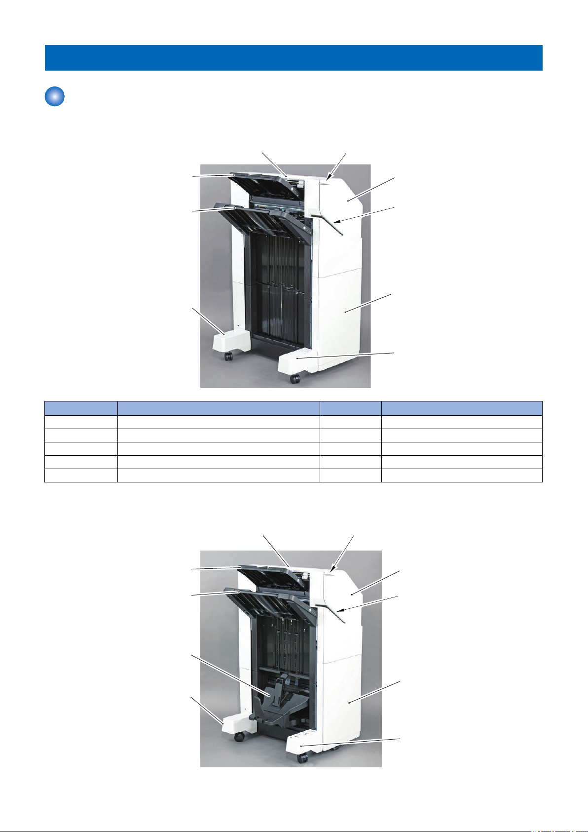
External View (Front)
■ Staple Finisher
1. Product Overview
No. Part Name No. Part Name
[1] Upper Cover Unit [6] Caster Cover (Front)
[2] Manual Staple Button [7] Caster Cover (Rear)
[3] Front Cover [8] Stack Tray
[4] Manual Staple Paper Inlet (Slit) [9] Escape Tray
[5] Lower Front Cover - -
■ Booklet Finisher
14
No. Part Name No. Part Name
[1]
[2]
[1]
[1] Upper Cover [6] Caster Cover (Front)
[2] Manual Staple Button [7] Caster Cover (Rear)
[3] Front Cover [8] Saddle Delivery Tray
[4] Manual Staple Paper Inlet (Slit) [9] Stack Tray
[5] Lower Front Cover [10] Escape Tray
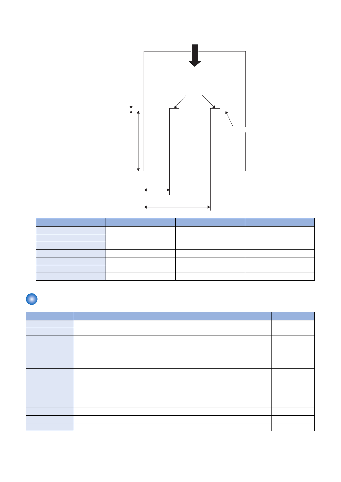
■ Buffer Pass Unit
1. Product Overview
No. Part Name No. Part Name
[1] Buffer Pass Delivery Tray [2] Buffer Pass Feed Outlet Port
External View (Rear)
■ Staple Finisher
No. Part Name
[1] Rear Cover
15
■ Booklet Finisher
[1]
[1]
No. Part Name
[1] Rear Cover
1. Product Overview
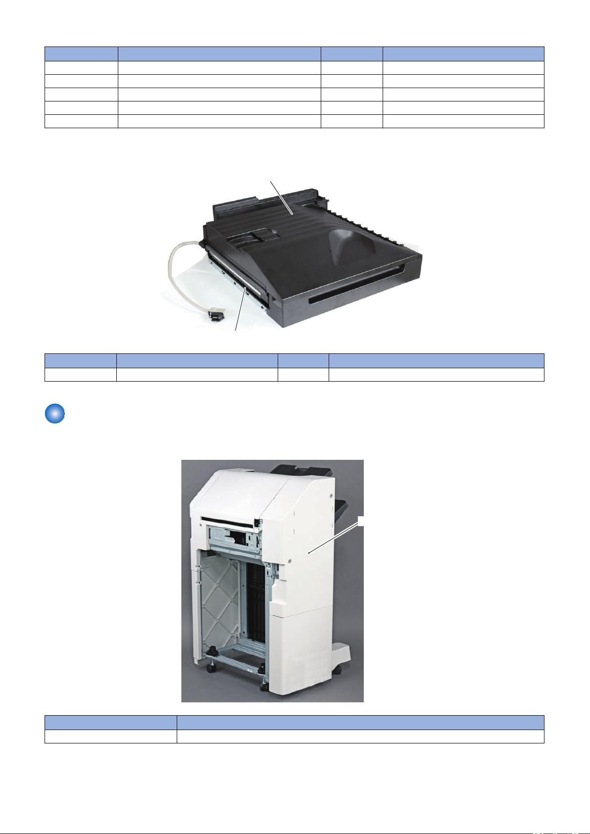
■ Buffer Pass Unit
No. Part Name
[1] Buffer Pass Feed Inlet Port
16
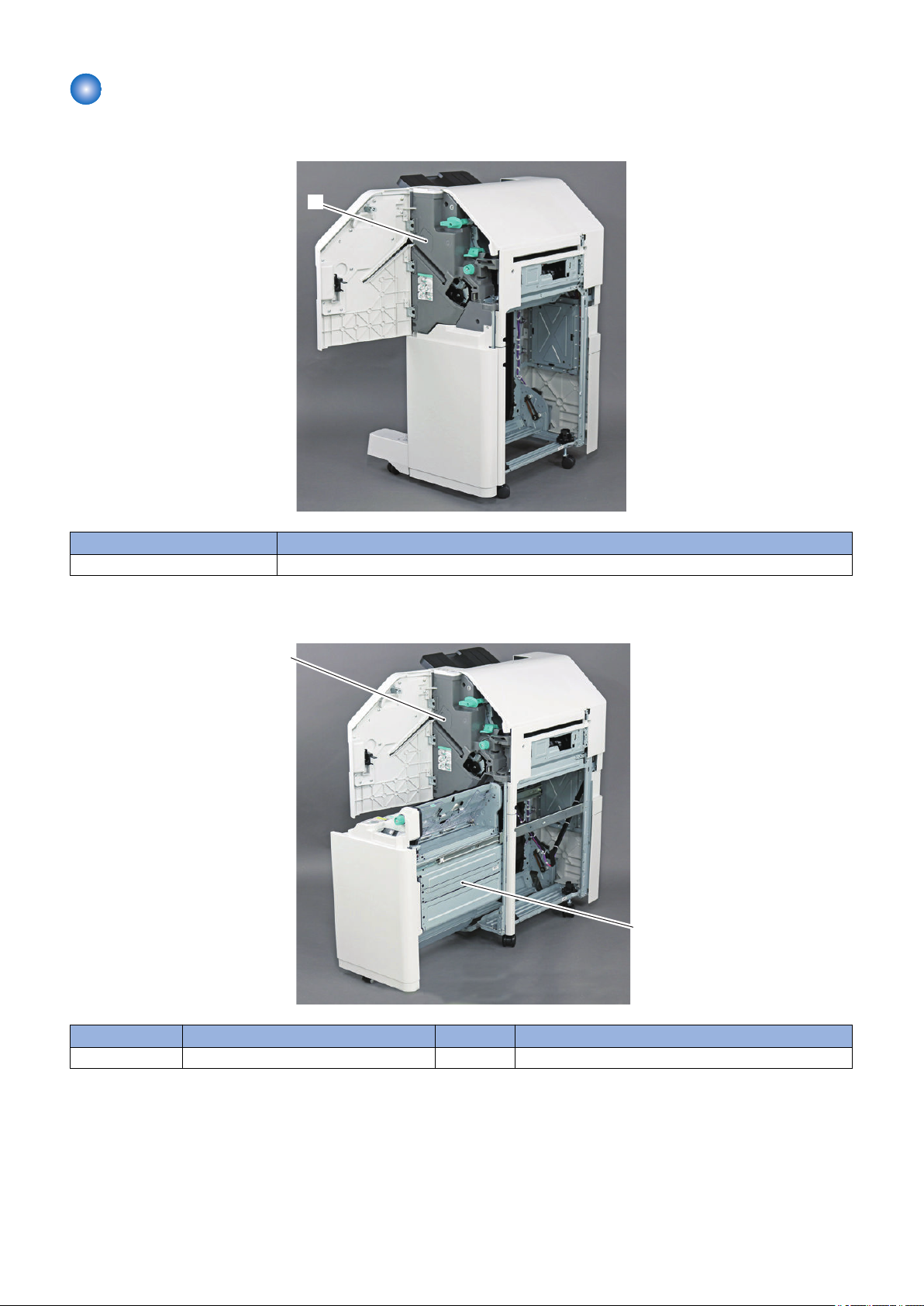
External View (Internal)
[1]
[1]
[2]
■ Staple Finisher
1. Product Overview
No. Part Name
[1] Front Inner Cover
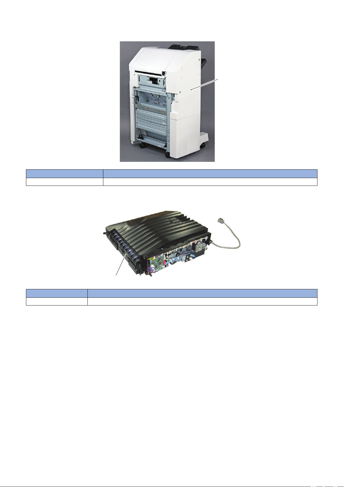
■ Booklet Finisher
No. Part Name No. Part Name
[1] Front Inner Cover [2] Saddle Unit
17
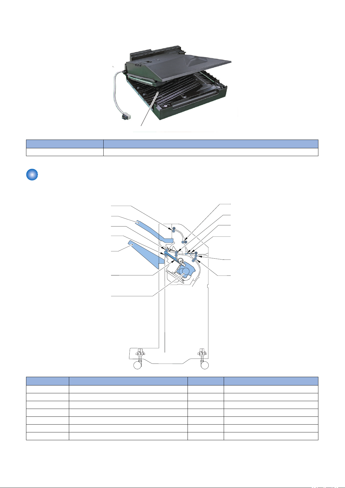
■ Buffer Pass Unit
[1]
[1]
[2]
[4]
[3]
[5]
[6]
[7]
[13]
[12]
[11]
[10]
[9]
[8]
No. Part Name
[1] Buffer Pass Feed Part
Cross Section
1. Product Overview
■ Staple Finisher
No. Part Name No. Part Name
[1] Escape Delivery Roller [8] Escape Feed Roller 1
[2] Escape Tray [9] Pre-Processing Roller
[3] Upper Stack Delivery Roller [10] Buffer/Saddle Inlet Flapper
[4] Lower Stack Delivery Roller [11] Escape Inlet Flapper
[5] Stack Tray [12] Inlet Roller
[6] Alignment Plate [13] Buffer/Saddle Inlet Roller
[7] Stapler Unit - -
18

■ Booklet Finisher
[1]
[2]
[4]
[3]
[5]
[6]
[7]
[9]
[8]
[10]
[19]
[18]
[17]
[16]
[15]
[14]
[13]
[12]
[11]
[1]
[4]
[3]
[2]
1. Product Overview
No. Part Name No. Part Name
[1] Escape Delivery Roller [11] Escape Feed Roller 1
[2] Escape Tray [12] Pre-Processing Roller
[3] Upper Stack Delivery Roller [13] Buffer/Saddle Inlet Flapper
[4] Lower Stack Delivery Roller [14] Escape Inlet Flapper
[5] Stack Tray [15] Inlet Roller
[6] Alignment Plate [16] Buffer/Saddle Inlet Roller
[7] Stitcher Unit [17] Stapler Unit
[8] Paper Folding Roller [18] Saddle Feed Roller
[9] Saddle Delivery Roller [19] Paper Pushing Plate
[10] Saddle Delivery Tray - -
■ Buffer Pass Unit
No. Part Name No. Part Name
[1] Buffer Pass Feed Roller 1 [3] Buffer Pass Feed Roller 3
[2] Buffer Pass Feed Roller 2 [4] Buffer Pass Feed Roller 4
19
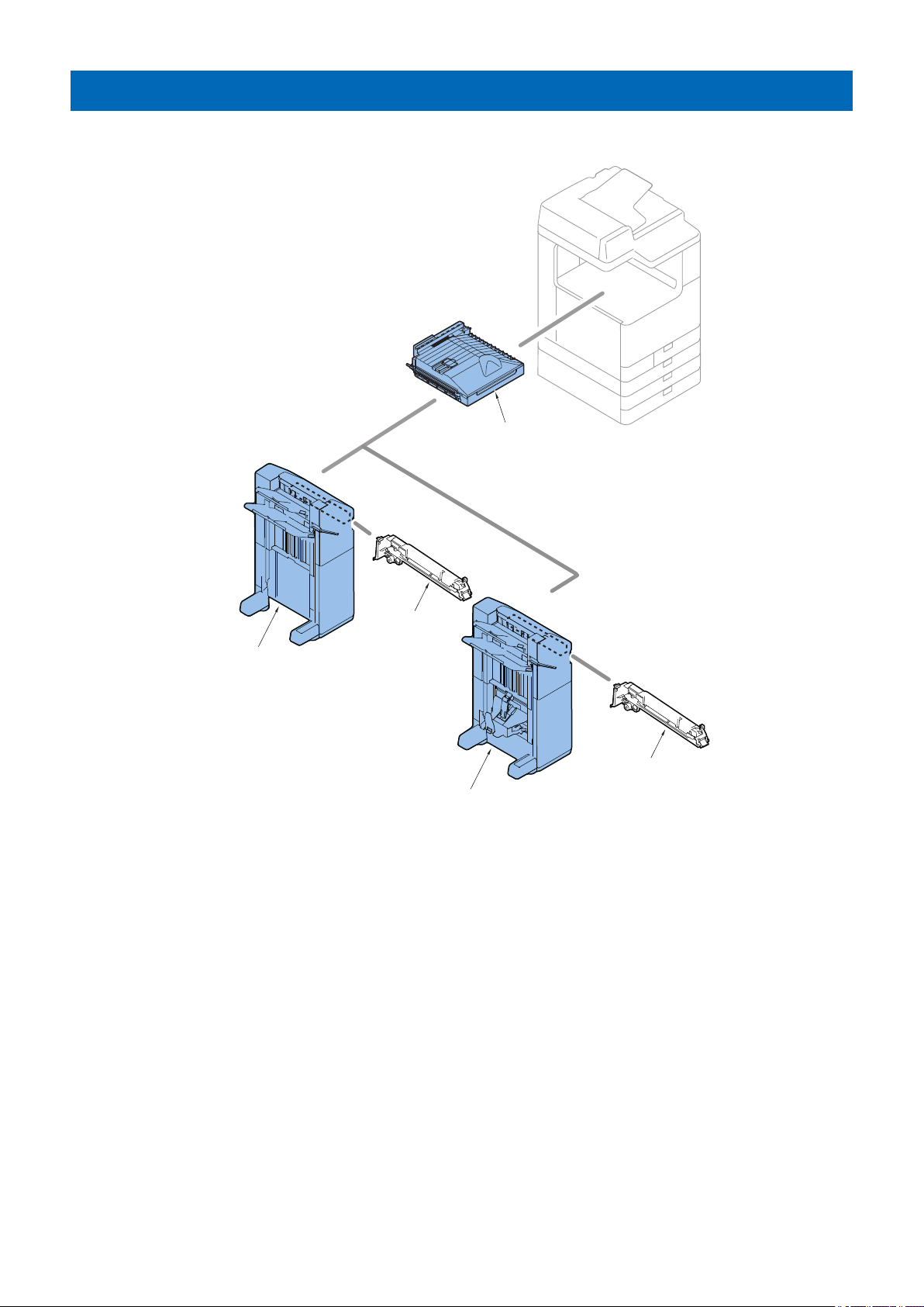
Optional Configuration
Buffer Pass Unit
Puncher Unit
Puncher Unit
Booklet Finisher
Staple Finisher
This equipment can incorporate a puncher unit (option).
1. Product Overview
20

Technical
2
Explanation
Basic Configuration.............................22
Controls...............................................25
Basic Operation...................................26
Feeding Unit........................................31
Stack/Escape Tray Unit.......................40
Processing Tray Unit...........................46
Saddle Stitcher Unit............................ 59
Buffer Pass Unit.................................. 67
Jam Detection..................................... 69
Power Supply......................................73
Upgrading ...........................................74
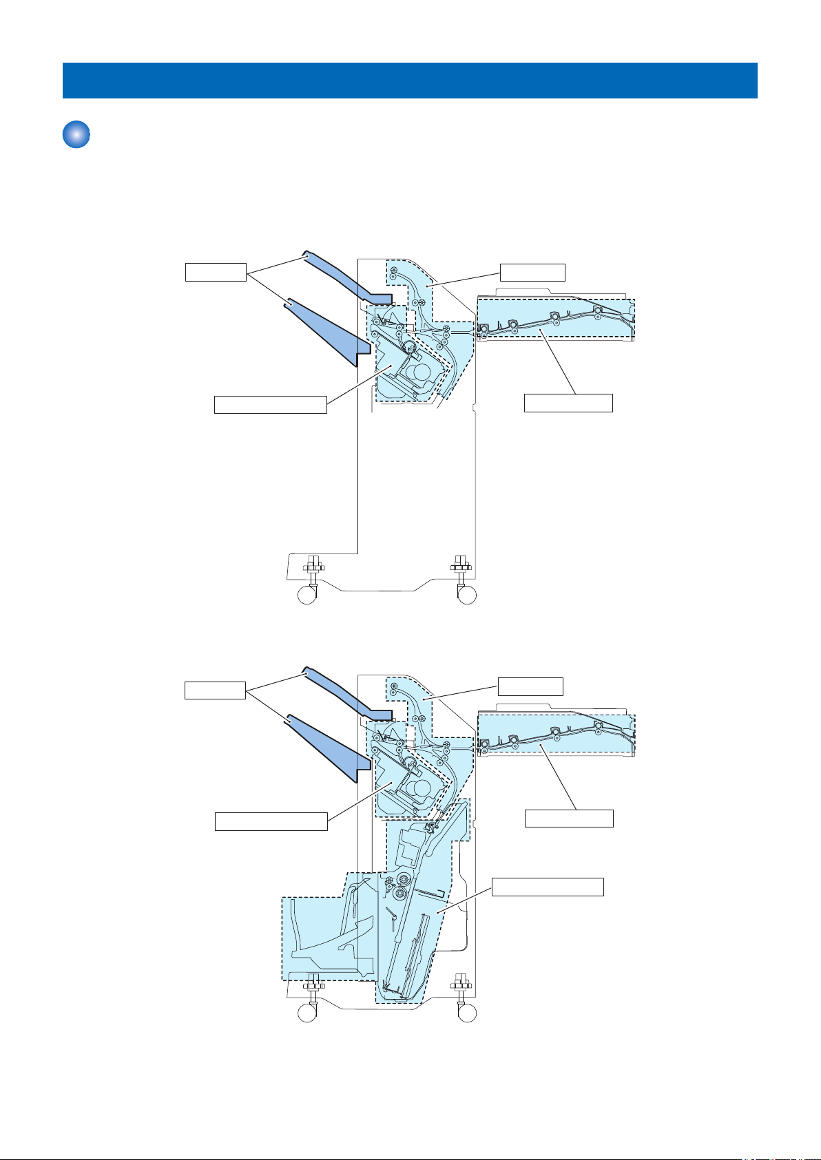
Tray Unit
Feed Unit
Processing Tray Unit
Buffer Pass Unit
Tray Unit
Feed Unit
Processing Tray Unit
Saddle Stitcher Unit
Buffer Pass Unit
2. Technical Explanation
Basic Configuration
Component Configuration
The components of this finisher are organized into 5 major blocks ; Buffer Pass Unit, Feed Unit, Processing Unit, Stack Tray Unit
and Saddle Stitcher Unit.
• Staple Finisher
• Booklet Finisher
22
 Loading...