

Page 1
Page 2
Page 3

PICTORIAL OUTLINE FOR USING THE CAMERA
Load the battery.
Turn the main switch on.
Load the film.
Look into the viewfinder.
Compose the picture and focus.
Out of Focus
In Focus
Determine the exposure by adjusting
the shutter speed dial and the aperture
ring.
o
Page 4

Congratulations upon the purchase of
your new Canon AT-1, a remarkably
advanced camera that reflects the latest
trends in SLR photography. As a
flawless product of Canon technology,
its vast potential as a rewarding means
of expression is assured for years to
come by an incomparable system of
fine lenses and accessories.
At an extremely reasonable price, the
Canon AT-1 offers you TTL Central
Emphasis Metering plus many of the
superb advantages enjoyed by users of
its all-electronic counterpart, the Canon
AE-1. Its fabulous electronic system
consisting of the Power Winder A for
continuous rapid-fire shooting, the
Speedlite 155A for perfectly synchro
nized flash shooting and the Data Back
A for automatic data imprinting give
the AT-1 unsurpassably versatile per
formance. Similarly, you have the
entire system of superior FD inter
Page 5

changeable lenses at your disposal
which enable metering at full aperture.
But perhaps most conspicuous is the
absence of mechanical noise that is
characteristic of conventional SLRs.
The AT-1 incorporates a wonderfully
silent electromagnetic release, in
addition to a 10-second electronic selftimer, for perfectly vibrationless
operation. Moreover, you will surely
find the Canon AT-1, with its
extremely compact and lightweight
body to be one of the easiest to operate
cameras ever.
In order to derive full benefit from the
many features the AT-1 affords, please
take the time to read and understand
the following instructions. Canon
remains always ready to lend you its
support in the future with a system of
lenses and accessories unequaled the
world over.
Page 6
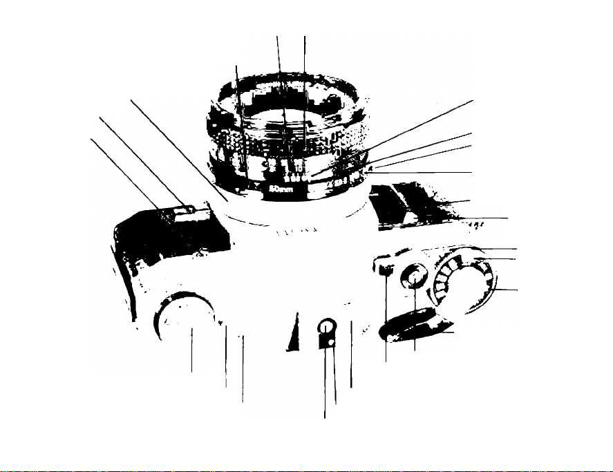
Distance Scale (in feet and meters) Focusing Ring
Aperture Ring
Canon Breech-Lock Ring
Stopped-Down Lever
Flash Terminal
Film Rewind Crank
Main Switch (Battery Check Lever)
While reading the instruction booklet, unfold this flap and the flap on the back cover to facilitate your
understanding of the instructions.
Fil.m Plane Indicator
Shutter Release Button
Electronic Self-Timer Lever
(Shutter Release Lock)
Accessory Shoe
Automatic Flash Contact
Synchronization Contact
Distance Index
Depth-of-Field Scale
EE Lock Pin
"A" Mark
Battery Chamber Cover
Finger Grip
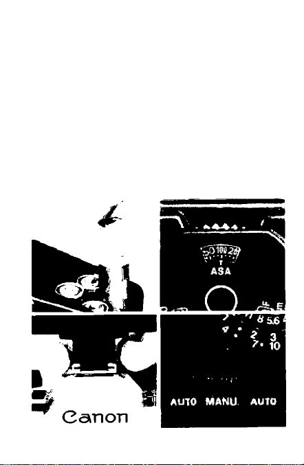
Film Speed
Set Ring
ASA Film
Speed
Shutter Speed
Dial
-----
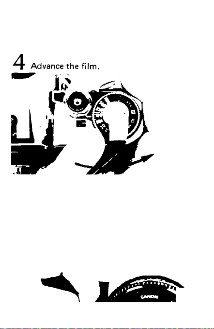
Film Advance Lever
Page 7
Page 8
Press the shutter button.
7
I,
Салол
•IL
Page 9
Photography with the Canon Speedlite
155 A
1. Take off the battery chamber cover and
load the batteries.
2. Set the ASA film speed of the 155A.
3. Mount the Speedlite 155A on the acces
sory shoe of the camera.
4. Turn the main switch on.
5. Set the AUTO/MANU. switch.
6. Set the prescribed f/stop on the lens.
7. Focus and press the shutter button.
Page 10
Photography with the Canon Power
Winder A
Remove the Battery Pack A.
1.
Load the batteries into the Battery Pack A.
2.
Attach the Battery Pack A to the Power
3.
Winder A.
Take off the winder coupler cover on the
4.
bottom of the camera body and put it in
the winder coupler's cover holder.
Attach the Power Winder A to the
5.
camera.
Turn the main switch on.
6.
Focus and press the shutter button.
7.
Page 11

CONTENTS
SPECIFICATIONS............................................8-10
Handling the Case and Lens Cap .... 12-13
Mounting the Lens............................................ 13
Loading the Battery and Main Switch . .14-15
Checking the Battery........................................ 16
Film Advance and Shutter Release ... 17-18
Loading the Film
Frame Counter.................................................. 21
Setting the ASA............................................ 22-23
OPERATION FOR GENERAL
PHOTOGRAPHY................................................ 25
Selecting the Shutter Speed .......................27-28
Lens Aperture
Viewing and Focusing...................................... 29
Dioptric Adjustment Lenses............................ 30
Viewfinder Information..................................... 32
Determining the Exposure
Meter Coupling Range...................................... 35
Holding the Camera ......................................... 37
Releasing the Shutter and
Rewinding the Film
DETAILED OPERATION OF
THE AT-1
Effects of Changing the Shutter Speed
and the Aperture
.........................................
...................................................
...............................
.....................................
..........................................................
..........................................
19-20
28
33
38-39
41
43-44
Page 12

Depth-of-Field
Using the Self-Timer
Flash Photography with the AT-1
Long Exposures................................................ 50
Stopped-Down Metering....................................52
Manual Aperture Control
Lenses.......................................................... 55-58
ACCESSORIES, CARE OF THE
CAMERA, MAINTENANCE, AND
MISCELLANEA
Canon Speedlite 155A...................................... 61
Canon Power Winder A
Canon Data Back A and Bellows FL . . . . 63
Other Accessories........................................64-65
Care and Storage of the Camera
...............................................
....................................
...................
............................
.................................................
....................................
..............
45-46
47-48
49
53-54
59
62
67-69
Page 13

SPECIFICATIONS
Type; 35mm SLR (Single-Lens-Reflex)
Camera with focal plane shutter.
Picture Size: 24 x 36mm
Interchangeable lenses: Canon FD series
lenses for full aperture metering. Canon
FL series lenses for stopped-down
metering.
Standard Lenses: Canon FD 55mm f/1.2
S.S.C.
Canon FD 50mm f/1.4 S.S.C.
Canon FD 50mm f/1.8 S.C.
Lens Mqunt: Canon Breech-Lock Mount.
Canon FD, FL, and R lenses can be
mounted for use.
Viewfinder: Fixed eye-level pentaprism.
Field of View: 93.5% vertical and 96.3%
horizontal coverage of the actual picture
area.
Magnification: 1:0.82 at infinity with a
standard 50mm lens.
Dioptric Adjustment Lens S: Standard —1
diopter.
Interchangeable with -t3, +2, -1-1.5, -i-1,
-(■0.5, 0, —0.5, —2, —3, and —4 diopters.
Page 14

Focusing Screen: Split-image/microprism
rangefinder surrounded by matte screen
Viewfinder Information: Meter needle and
aperture needle (circular index) are seen
on the right hand side of the viewfinder.
On the upper right hand is an overexposure/battery check index mark and
on the lower right hand is a metering
limit index mark on the underexposure
side.
Viewfinder Attachments: Angle Finder A2
and B, Magnifier S, Dioptric Adjustment
Lens S (10 kinds), and Eyecup 4S.
Mirror: Instant-return, large reflector mirror
with shock absorbing mechanism.
Exposure Meter: Built-in. Using CdS photo
cell. Coupled to shutter speeds, film
speeds, and f/stops. Match needle type,
TTL full aperture metering mechanism.
Light Metering System: TTL (Through-The-
Lens) Central Emphasis Metering method
Exposure Meter Coupling Range: EV 3 (f/1.4
at 1/4 sec.) to EV 17 (f/16 at 1/500
sec.) at ASA 100 film with FD 50mm
f/1.4 S.S.C. Lens.
Film Speed Range: ASA 25 to ASA 3200
Page 15

Shutter: Cloth focal plane shutter with four
spindles. Shock and noise damping
mechanisms are incorporated. All shutter
speeds are electronically controlled.
Shutter Speeds: 1/1000, 1/500, 1/250,
1/125, 1/60, 1/30, 1/15, 1/8, 1/4, 1/2, 1,
2 (seconds) and B.
X synchronization is at 1/60 seconds.
Shutter Speed Dial: The shutter speed dial is
on the same axis as the film advance
lever. The number 2 for two seconds is
marked in orange; other numbers as well
as X synchronization are in white. There
is a shutter dial guard to prevent uninten
tional movement of the dial. The ASA
dial is located underneath the shutter
speed dial.
Self-Timer: Electronically controlled self-
timer. After the self-timer lever is pushed
forward, the self-timer is activated by the
shutter release button. The self-timer
releases the shutter after a time lag of 10
seconds. A self-timer LED lamp blinks on
and off when the self-timer is in
operation. The self-timer operation can
be cancelled while in operation.
Page 16

Stopping-Down the Lens: Stopping-down
the lens can be performed by pushing the
stopped-down lever after setting the
aperture ring.
Power Source: One 6V silver oxide battery;
Eveready No. 544, UCAR No.544, JIS
4G13, and Mallory PX28. The battery
lasts the equivalent of 20,000 shutter
releases, or one year under normal use.
Battery Check: Battery power level can be
checked by the meter needle inside the
viewfinder -when the main switch is
turned to the battery check index mark
"C".
Flash Synchronization: X synchronization
is at 1/60 sec. M synchronization is at
1 /30 sec. and below.
Flash Terminal: The accessory shoe has a
direct flash contact and automatic flash
control contact. On the front of the
camera body is the flash terminal, JIS-B
type for flash units with a cord. It has a
built-in protective rim to prevent elect
rical shock.
Automatic Flash: With the Canon Speedlite
1 55A, set the aperture to the prescribed
Page 17

f/stop, and the amount of light is auto
matically controlled for correct flash
exposure, adjusting the shutter speed to
1/60 of a second automatically.
Back Cover: The camera's back cover has a
memo holder for your convenience. The
cover can be removed for attaching the
Canon Data Back A.
Film Loading: Performed by pulling up the
rewind crank to open the back cover.
Easy film loading with multi-slot take-up
spool.
Film Advance Lever: Single stroke with 120°
throw and 30°stand-off. The film can be
wound with several short strokes. The
Canon Power Winder A can be mounted
for automatic winding of the film.
Frame Counter: Additive type. Automatical
ly resets when the back cover is opened.
While rewinding film, it counts back the
frame numbers.
Film Rewinding: Performed by pressing the
rewind button on the bottom and by us
ing the rewing crank on the top. The
rewind button is automatically reset
when the film is advanced with the film
10
Page 18

advance lever.
Size: 141 X 87X47.5mm (5-9/16"x -3-7/16"
X 1-7/8") body only.
Weight: 590g (20-13/16 ozs.) body only.
790g (27-7/8 ozs.) with the 50mm f/1.8
S.C. lens.
895g (31-9/16 ozs.) with the 50mm f/1.4
S.S.C. lens.
1,100g (38-13/16 ozs.) with the 55mm
f/1.2 S.S.C. lens.
Subject to change without notice.
Page 19
Page 20
\2
f
t
i - ,v
i':'
«
Page 21

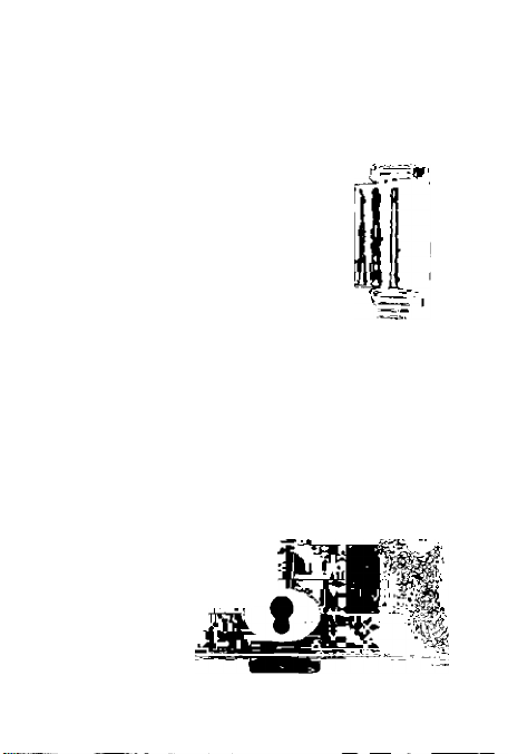
PRELIMINARY PREPARATION
Neckstrap and Case
Slide the scratch prevention ring and
spare battery case which houses a spare
battery onto the Canon AT-1 's neckstrap,
then thread the neckstrap through the rings.
Adjust the neckstrap to a length most suitable
for you.
Firmly attach the case to the camera by
turning the screw on the bottom of the case.
When you wish to take off the top cover of
the soft case, turn the top cover to the
bottom then slide it straight up in the direc
tion of the arrow and pull it out as indicated
in the photo.
Page 22

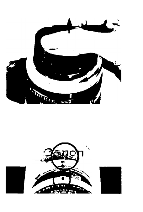
Handling the Lens Cap
The lens cap can be removed from the
front of the lens after pressing in the tabs on
both sides of the cap. The rear dust cover can
be removed by turning the Canon BreechLock ring in the direction of the arrow. To
attach the dust cover, align its slot with the
positioning pin below the red dot of the
Breech-Lock ring, and press it in. When the
dust cover is removed, the Breech-Lock
ring is locked.
Mounting the Lens
Remove the body cap. Make sure that the
aperture ring is not set to the "A" mark
before mounting the lens. Release the
aperture ring from the "A" mark by pushing
the EE lock pin and turn the ring. Then,
mount the lens by aligning the red dot of the
body with the red dot of the bayonet ring,
and then turning the Breech-Lock ring clock
wise, pressing gently until it locks into
position. Reverse the procedure to dismount
the lens.
Page 23
л
-I,
'ii
13
Page 24
Page 25

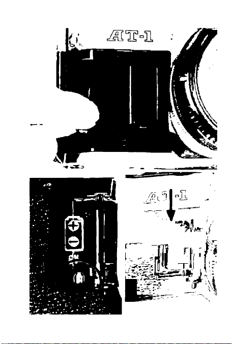
Loading the Battery
The camera will function only when the
battery is loaded and the main switch is turn
ed on. Use a silver oxide battery for the power
source. The battery chamber cover can be
opened more easily by using the viewfinder
cover that is inserted into the accessory shoe.
Be careful to load the battery correctly
with the "+" side up following the diagram on
the inside of the battery chamber. If the bat
tery is incorrectly loaded so the polarities are
facing the wrong direction, the camera will
not function. Load the battery by inserting
the " contact first while holding down the
battery in the bottom of the battery chamber.
When loading or removing the battery, make
certain that the main switch is set at OFF.
■ Only a silver oxide battery can be used
and other types cannot be used. In general
use, the battery will last one year. Safety
circuitry is built in the camera to keep the
shutter from being released when the voltage
of the battery becomes insufficient.
Page 26

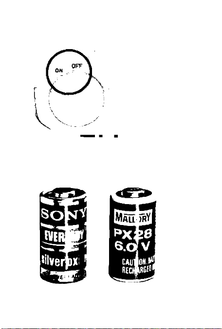
Main Switch
The main switch turns on or off the elect
ric circuits of the camera. Therefore, when
taking photographs, set the main switch to the
"ON" position. The camera will not function
unless it is set to "ON".
■ When not in use, turn the main switch to
"OFF" to guard against needless consumption
of the battery.
i_
I Silver Oxide
Battervi 6V)
Usable Batteries
Eveready(UCAR) No.544
JIS 4G13, Mallory PX28
Page 27
15
Page 28
Page 29

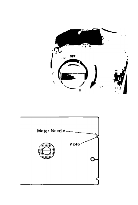
Checking the Battery
If there is not sufficient voltage, the
camera will not function, so check the battery
as indicated below. The main switch is also
used when checking the battery. Turn the
main switch/battery check lever as far to the
left as possible or, in other words, to the "C"
index on the outer side of the film rewind
crank while looking into the viewfinder to see
if the power level is sufficient. If the meter
needle rests above the battery check index
mark, there is sufficient voltage. If it is below
the index mark, replace the battery as there is
not enough voltage left in the battery for the
camera to operate.
Perform a battery check in the follow
ing situations:
1. When a battery is loaded.
2. If the shutter does not function.
3. When a great number of photographs
have been taken.
4. When the camera is used after it has been
stored for a long period without use.
When the camera is used in extremely
5.
cold conditions.
Page 30

Film Advance and Shutter Release
Turn the film advance lever until it stops,
so the film will advance one frame all in one
motion. The shutter will cock, and the dia
phragm and mirror will be ready for the next
shutter release, while the frame couriter
advances simultaneously to the next number.
By pushing the film advance lever lightly with
the tip of your thumb, it will open to its 30°
stand-off position away from the camera body
for easy film advance.
While the film is advancing, the shutter will
not be released. Film winding can also be
accomplished by advancing the lever in short
strokes.
Canon has developed the Power Winder A
to be used with the AT-1 for automatic film
winding. It greatly increases the speed and
mobility of the AT-1. (See page 62.)
Page 31

17
Page 32

Page 33

Shutter Button and Shutter Lock
The magnetic release shutter button
enables smoother shutter release than the
mechanical release method does. There is also
less chance for camera shake.
When the shutter lock lever around the
shutter release button is turned to the "L"
position, the shutter button will be locked to
prevent unintentional shutter release. Keep
the shutter release button locked while
carrying the camera to prevent film waste.
When the power level of the battery is
insufficient, a safety mechanism will keep the
shutter from being released.
■ At temperatures under —20 degrees C,
there may be an occurrence when the shutter
will not be released depending on the
batteries, even if the battery power is suf
ficient. In that cold condition, the battery's
power is reduced so some 10 seconds should
be allowed after the battery is checked before
taking a picture.
Page 34

Loading the Film
The Canon AT-1 uses color or black and
white film in standard 35mm cartridges.
Opening the Back Cover
To load a cartridge of film into the
camera, first open the camera's back cover.
Pull up the rewind crank and the back cover
will pop open. The back cover can be securely
closed simply by pressing it until it locks.
Avoid direct sunlight when loading or un
loading the film.
The Canon Data Back A, an accessory for
imprinting data such as the day, month and
year, can be attached to the AT-1 in place of
the back cover. (See page 63.)
How to Load the Film
Put the cartridge into the film cartridge
chamber and press down while rotating the
rewind knob until it drops securely into
position. The protruding part of the cartridge
should be on the bottom. Pull the film leader
across and insert the end into one slot of the
multi-slot take-up spool. Turn the film ad
vance lever and wind the film around the
Page 35

19
Page 36

20
Page 37

take-up spool making sure that the perfora
tions of the film are engaged in the teeth of
the film transport sprocket.
Then, make sure that there is no film
slack. In case there is, gently turn the film
rewind crank in the direction of the arrow to
obtain proper film tautness and the film ad
vance lever to ensure that the leader is wound
fully on to the take-up spool before the
camera back is closed.
When loading the film into the camera,
do not touch the shutter curtain, the film rails
or the pressure plate.
Closing the Back Cover
Close the back cover until it snaps shut.
Gently turn the film rewind crank clockwise
in the direction of the arrow to take up the
film slack. Then, advance the film a couple of
times pressing the shutter button until the
first exposure appears in the frame counter.
Page 38

Frame Counter
The frame counter is an additive type
which counts one frame every time the film
advance lever winds the film. When the
camera's back cover is opened, the frame
counter automatically resets itself to the "S"
position.
While rewinding film, the frame counter
counts back the frame numbers. The starting
position "S", 0, and the even numbers 2 to 38
are displayed by the counter. Numbers 20 and
36 are marked in orange to call your attention
to the end of commercially available film
cartridges. The frame counter cannot count
higher than 38.
Page 39

г\
Page 40

22
Page 41

Checking Film Winding
Operate the film advance lever while
watching the film rewind knob. If it rotates,
the film is properly loaded. If the rewind
knob does not rotate, open the back cover
and load the film again from the start.
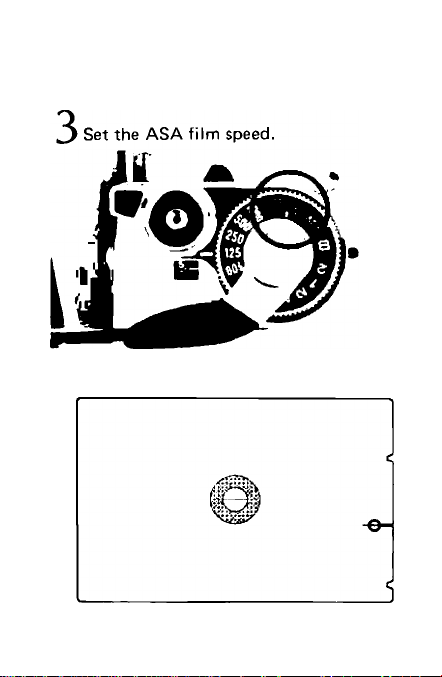
Setting the ASA Film Speed
After loading the film, set the ASA film
speed according to the ASA speed of the film
in use. To set the ASA, first push the film
advance lever out to its 30° stand-off position
away from the camera body, then gently lift
up the ASA ring around the shutter dial and
rotate it in either direction until the proper
number is aligned with the green index mark.
ASA is a numerical rating of a film's sensitivi
ty to light. A higher ASA number indicates a
faster film which is more sensitive to light. On
the other hand, a lower ASA number indicates
a slower film which is less sensitive to light.
The ASA rating recommended by the manu
facturer is printed on the film box, e.g.,
ASA 100.
Page 42

The following ASA ratings can be set on
the camera. Figures in parentheses indicate
intermediate film speeds.
. ^ 32 40 6^ fO , 12
ASA25 • ’50 • • 100 •
* 800'*1600™ '-“"3200
'60 250 320
■ 200 • • 400
Use of the Memo Holder
The memo holder on the camera's back
cover is useful for keeping data like film
speed, location, shooting. For example, after
tearing off the part of the film box which
specifies the type of the film being used, it
can be inserted into the memo holder as a
constant reminder.
Page 43

Kodacolor II
23
Page 44

Page 45

Operation for Generol Photogrophy
25
Page 46

Page 47

Shutter and Aperture
The opening of the shutter letting light
in on the film is called an exposure. The
amount of light striking the film is controlled
by the lens aperture, while the length of time
that light is allowed to strike the film is
controlled by the shutter.
Shutter Speed Dial
The shutter dial is used to adjust the
shutter speed. It allows for speed settings in
the range of 2 seconds to 1/1000 of a second.
When the shutter speed is advanced to the
next larger number, the exposure time is cut
in half. The shutter speeds on the dial are
typically the reciprocals of the true shutter
speeds. For example, 125 and 250 on the dial
represent shutter speeds of 1/125 and 1/250
of a second. Only in the case of the orange
"2" is the shutter speed actually as indicated
on the dial, i.e., 2 seconds. The "B" (Bulb)
setting is used for long exposures where as
long as the shutter button is pressed down,
the shutter will remain open.
■ The shutter speed dial cannot be set to an
intermediate position.
Page 48

1 ndoors
Brightness
Shutter Speed
(Seconds)
1/30 to 1/60
Outdoors
Mid-summer Beach or
Snow-coverd Mountains
1/125 to 1/250
1/500 to 1/1000
Selecting the Shutter Speed
Shutter speed is determined in accor
dance with the brightness of the scene and the
speed with which the main subject is moving.
You can use the above table as a general guide
27
Page 49

to help you select an appropriate shutter
speed when using a standard 50mm lens. For
indoor photography, with no special illumi
nation, choose 1/30 of a second and 1/60 of
a second in a brightly lit room.
For outdoor photography, select 1/125
second when cloudy and 1/250 second in
sunshine. To take pictures in particularly
bright sunshine such as at a beach in mid
summer or in snow-covered mountains, use
shutter speeds of 1/500 sec. or 1/1000 sec.
The above mentioned shutter speeds
apply when using a standard 50mm lens, but
it is necessary to choose faster shutter speeds
when using lenses of longer focal lengths
because they are more difficult to hold
steady. It is generally said that the shutter
speed figure should be greater than 1 divided
by the focal length of the lens in order to ob
tain sharp images.
For example, when using a 200mm tele
photo lens, shutter speed should be faster
than 1/200 second. Therefore, the shutter
speed in this particular case should be set at
1/250 sec. Image blur can also arise if the
camera is not properly held. See page 37.
28
Page 50

Lens Aperture
The adjustment of the aperture is used
with the shutter speed to get the correct ex
posure. The amount of light reaching the film
is controlled by the aperture's size.
On the aperture ring are a series of mark
ings which indicate the proportion of the light
allowed to pass through the lens, which are
known as f/numbers. When the aperture ring
is set to the next larger f/number on the scale
of the ring, the amount of light passing
through the lens is decreased by 1/2. The
lens's brightness is based on the smallest
numerical aperture value for the lens.
With a f/2 serving as the standard, the com
parative brightness at each f/stop will be as
indicated below.
Biighiness
(f/stop) 1.2
Ratio 3
The aperture ring can be set at positions
between the settings on the scale.
2.8 4 5.6 8 11 16
J1/2 1/4 1/8 1/16
2 1
1/22
1/64
Page 51

Viewing and Focusing
Focusing is performed in the small round
area in the center of the viewfinder. The
smaller central circle is a split-image focusing
screen and around it is the microprism ring.
The split-image rangefinder ascertains that the
image is "in focus" when the image divided
horizontally in half merges and becomes one
complete image.
The microprism rangefinder presents a
clear and steady image when in focus. The
microprism conveys a broken, shimmering
image when not accurately in focus. It is also
possible to focus with the matte screen
outside the smaller central area. You can
focus with any of these focusing aids as you
like, depending on the subject and your pre
ference.
Accessories such as an eyecup, dioptric
adjustment lenses, angle finders, and magnifier
can be attached to the viewfinder eyepiece.
Page 52

Out of Focus
In Focus
23
Page 53

30
Page 54

Dioptric Adjustment Lens S
Dioptric adjustment lenses can be
attached by inserting them from above into'
the grooves in the viewfinder eyepiece to
compensate for the individual eyesight. With
them, near-sighted or far-sighted persons can
perform photography without glasses.
The built-in eyepiece lens of the AT-1 has
—1 diopter. The following 10 kinds of
dioptric adjustment lenses are optional acces
sories: -1-3, + 2, -M.5, -1-1, -1-0.5, 0, —0.5, —2,
—3 and —4 (diopters).
One way of selecting the correct dioptric
adjustment lens for you is to select the one
that is the closest to your glasses in regard to
number of diopters. But, we propose that,
to select the most appropriate dioptric ad
justment lens, you actually look through
the viewfinder after placing it over the eye
piece.
Because the camera itself has —1 diopter,
the diopters of the lenses are recorded as the
real power when attached to the camera, thus
reflecting the power of the camera's viewfin
der.
Page 55

Angle Finder A2 and B
The angle finder is a magnifying glass
which can be attached from above into the
grooves of the viewfinder eyepiece. It rotates
90 degrees so that the image on the viewfinder
can be viewed directly from the side or above
whenever it is inconvenient or impossible to
look directly through the eyepiece. This is
very helpful in copying, close-ups, macro
photography, and photomicrography. There
are two types, the A2 whose image is reversed
as in a mirror, and the more advanced Angle
Finder B which gives a correct image.
Magnifier S
The Canon Magnifier S gives 2.5X magni
fication of the viewfinder center for precision
focusing in close-up work. The strength can be
adjusted to your eyesight within the range of
-f4 to —4 diopters.
The Magnifier S combined with its
adapter can be inserted into the grooves of the
viewfinder eyepiece. The adapter of the
Magnifier S is hinged to allow the magnifier to
swing upward from the eyepiece leaving the
whole screen image visible after focusing.
Page 56

31
Page 57

Viewfinder Information
The Canon AT-1 is a camera offering full
aperture metering with FD lenses where the
aperture needle is coupled to the shutter
speed, aperture and film's sensitivity when FD
lenses are used. Furthermore, when using
Canon FL lenses on the AT-1, the exposure
reading is performed with stopped-down
metering.
The Central Emphasis Metering method
of exposure measurement is used in the AT-1
to deliver the optimum exposure to the main
subject without being affected by the bright
sky in the upper part of the picture area.
32
Matte
Page 58

In the center of the viewfinder is a range
finder while the meter needle and the aperture
needle (circular) are found to the right. The
exposure metering range index marks are in
the upper and lower right. The exposure
metering range index mark in the upper right
is also used as the battery check index mark.
The exposure metering range extends from
EV 3 (f/1.4, 1/4 of a second) to EV 17 (f/16,
1/500 of a second) at ASA 100 film with FD
50mm f/1.4 S.S.C. lens.
Page 59

Determining the Exposure
Turn the camera toward the subject and
look into the viewfinder to insure that the
meter needle swings and rests still somewhere
between the upper and lower exposure
metering index marks. Then, turn the shutter
speed dial and/or the aperture ring until the
circular aperture needle bisects the meter
needle. These are the steps for getting the
correct exposure. On most occasions, it is
more convenient to predetermine the shutter
speed then turn the aperture ring.
The upper and lower halves each express half
an f/stop gradation; the full width of the
Page 60

aperture needle is equivalent to one f/stop.
Thus, the setting of the meter needle and
aperture needle can be precisely controlled
inside the viewfinder enabling finer adjust
ment of the exposure.
■ Exposure determination (matching
needles) should not be performed while the
shutter button is depressed. It will cause a
slight, variable error depending on the
condition of the battery.
0.5 f/stops
0.5 f/stops
33
Page 61

Operation of Shutter Priority
1. Turn the main switch on.
2. Set the shutter speed.
3. Look into the viewfinder and focus.
4. Turn the aperture ring and align the
meter needle with the aperture needle.
5. Depress the shutter button.
34
Page 62

Exposure Metering With FL Lenses
When Canon FL lenses are used on the
AT-1, it is necessary to take a stopped-down
meter reading. After pressing in the stoppeddown lever until it locks, adjust the aperture
ring and/or shutter speed dial until the meter
needle inside the viewfinder is aligned with
the aperture needle to obtain the correct
exposure. After determining the correct
exposure, release the stopped-down lever and
compose and focus at maximum aperture.
Page 63

Meter Coupling Range
If the circular aperture needle does not
align with the meter needle by turning the
aperture ring, it means that the shutter speed
is not properly set. If this is the case, reset
shutter speed dial so that two needles can be
aligned with each other. And when these two
needles cannot be aligned with each other by
turning the shutter speed dial, change the
aperture. When the shutter speed is set at a
slow speed outside the meter coupling range,
metering cannot be performed even if the
aperture is changed.
The built-in exposure meter couples to
the range of the aperture and shutter speed
with respect to the film speed. For example,
when using the FD 50mm f/1.4 S.S.C. lens
and ASA 100 film, the exposure meter
couples within the range of from EV 3 (f/1.4
at 1/4 sec.) to EV 17 (f/16 at 1/500 sec.).
Page 64

I
Film
I Speed
ASA 25 1
ASA 50
ASA 100
ASA 2001/8 1/15 1/30
ASA 4001/15 1/30 1/60
ASA 800
1/2
1/2
1/4
1/4 1/8 1/15
1/60
1/30
I/I251/2501/500
m 1600 1/60 1/1251/250
1/250
1/125
ASA 3200
Minimum
f/stop
1/500
f/^2 |{/22 f/22 f/22 f/2?
__L a
1/4
1/8 1/15 1/30
1/8 1/15
1/30
1/60
1/125
1/500
l/lOOi
1/30 1/60 1/1Z5
1/60 1/125 1/250
1/125
1/500 I/IOOO
1/250
1/2501/50Q
1/1000
1/1000
1/1000
f/22
f/22
1/60
...
1/125
1/250
1/500I/IOOO
1/250
1/5001/1000
... ...
f/I6
f/11 f/8
1/500
1/1000
f/5,6
35
Page 65

Page 66

Holding the Camera
The electromagnetic shutter release
button has a short, soft touch. The shutter
can be released by lightly depressing the
.shutter button to help prevent camera shake.
But, unsteady holding of the camera will
cause camera shake in spite of the electro
magnetic shutter release system.
Therefore, be sure to hold the camera
firmly. Rest the camera on your left palm and
grasp the lower part of the lens focusing ring
between your thumb and forefinger or middle
finger. Hold the right end of the camera
firmly, with your right thumb behind the tip
of the film advance lever and your right fore
finger on the shutter button, while the other
fingers hold the camera's finger grip.
To reduce camera shake, press your left
elbow strongly against your body and look
into the viewfinder steadying the camera
against the forehead. The right arm should be
relaxed while holding the camera.
Page 67

When you use comparatively slow shutter
speeds or when you use telephoto lenses, it is
advisable to lean against a wall, a tree trunk or
some fixed object for a steadier grip. The
above describes the fundamentals of how to
hold the camera. You may find yourself the
most appropriate grip for you and get ac
customed to it through constant practice.
37
Page 68

38
Page 69

Releasing the Shutter
When you press the shutter button, try to
squeeze the shutter button gently with your
finger. Avoid hitting or pressing the shutter
button suddenly particularly when using slow
shutter speeds, otherwise blur may result.
At the moment of shooting, you should
exhale slowly while the shutter button is
being pressed.
Rewinding the Film
When the film advance lever cannot travel
all the way to the end of its stroke, the frame
counter tells you that you have reached the
end of the film. You have to rewind the film
in its protective cartridge, before you can
remove it from the camera. Since it is not
protected, any exposure to light will "fog"
the film and cause a drastic color shift and
loss of picture image.
To rewind the film, press in the small
rewind button on the bottom of the camera,
Page 70

unfold the rewind crank and turn it in the
direction of the arrow on the rewind crank.
When the frame counter has reached the "S"
mark, you should stop rewinding. Then pull
up the rewind knob to open the camera back
and lift the cartridge out.
If you stop rewinding the moment the
frame counter has reached the "S" mark, the
film will not be completely rewound into the
cartridge and the film leader will still be
outside the cartridge.
Page 71

зэ
Page 72

40
Page 73

D«iQiled Operation of the AM
41
Page 74

“Ж
Page 75

Concerning the Exposure (Shutter
Speed and Aperture Coupling)
In order to obtain the correct exposure, it
is necessary to correctly match the shutter
speed with the aperture. The shutter speed
and the aperture are the main factors in
controlling the amount of light which is
allowed to strike the film, and when they
change, the quality of the image upon the film
also changes.
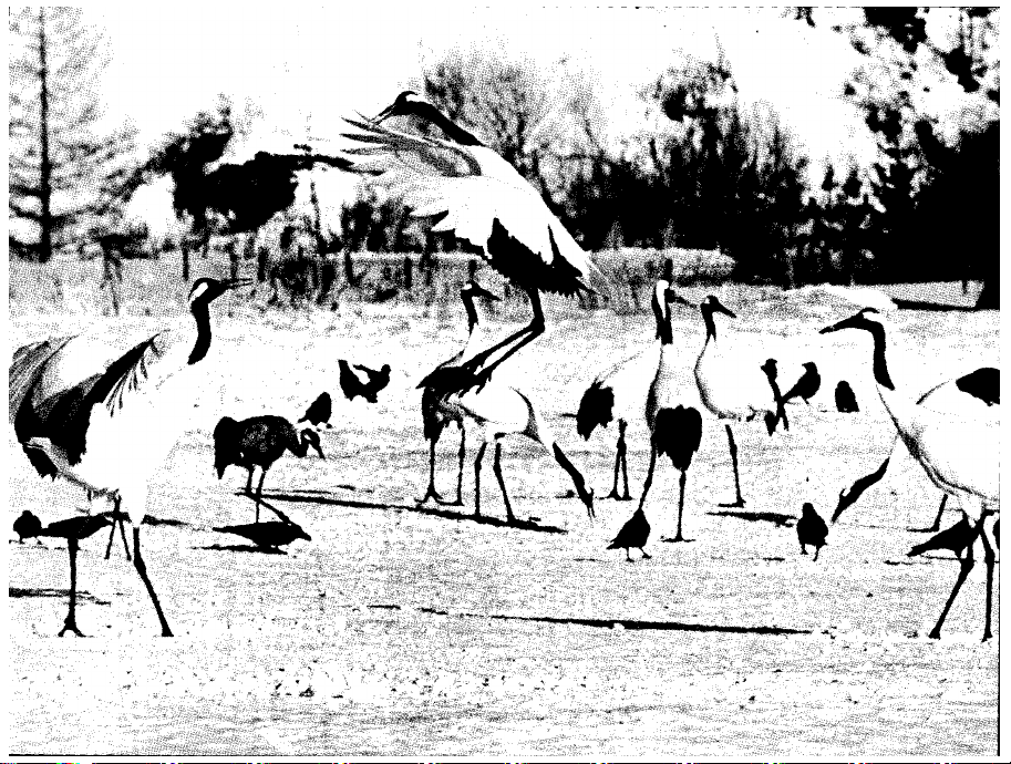
Effects of Changing the Shutter Speed
The explanations below are pertinent to
photography with fast moving subjects or
when it is intended to produce impressionistic
pictures of movement. Depending on the
selection of the shutter speed, you can freely
control the expression of movement.
If, as in example A, the photo is taken at
a shutter speed of 1/1000 sec., the movement
will be frozen. If, as in example B, with the
same subject, the photo is taken at a shutter
speed of 1/60 sec. with a panning technique,
the movement is well expressed.
Panning is really quite a simple technique.
Hold the camera firmly and continue twisting
the upper part of your body while following
Page 76

43
Page 77

44
Page 78

the moving main subject in the viewfinder.
You then release the shutter while still twist
ing. When you use this technique, the main
subject should be sharp even at slow shutter
speeds and the image of the background is
blurred according to the speed of the panning
movement. This hightens the feeling of
motion in the picture.
Effects of Changing the Aperture
The lens aperture does not only control
exposure but it also has an effect on the
photograph as follows:
In example C, the aperture was set at
f/5.6 with the shutter speed dial adjusted
before shooting. In example D, a f/16 setting
was used to clearly demonstrate the diffe
rence. In C, the miniature cars in the back and
front are blurred and only the miniature cars
in the central area are in focus. In D, most of
the miniature cars are sharp and clear. Thus,
the lens aperture has a marked effect on how
much of the picture is reproduced sharply.
Page 79

Depth-of-Field
When a certain subject is brought into
focus, there is only a limited range in the
foreground and background of the subject
which can be kept clearly in focus. This zone
of sharpness is the depth-of-field.
There are two methods of confirming the
extent of the depth of the field: by stopping
down the lens diaphragm or by reading the
depth-of-field scale on the lens.
Confirming the Depth-of-Field by
Stopping-Down the Lens Diaphragm
Press the stopped-down lever until it
locks. Once locked, the depth-of-field can be
checked by looking into the viewfinder. Thus,
the extent of the depth-of-field can be seen as
the zone of sharpness in the subject field
observed on the screen. When the stoppeddown lever's release button is pressed, full
aperture metering will be restored.
Page 80

45
Page 81

Generally, the depth-of-field will become
deeper as the aperture becomes smaller, and
shallower as the aperture becomes larger. A
shorter focal length as well as a greater
camera-to-subject distance will also deepen
the depth-of-field.
Comparing a 28mm lens with a standard
50mm lens set at the same f/stop, the 28mm
lens's depth-of-field will be greater. And when
the photographic distance changes, the depthof-field changes, too. For example, if the same
subject is photographed from three and then
from seven meters away, the sharp foreground
46
Page 82

and background of the subject will be deeper
at the greater distance.
Depth-of-Field Scale on the Lens
A depth-of-field scale is engraved on the
lens barrel, shown as a series of f/numbers on
each side of the distance index mark opposite
the distance scale. Focusing and depth-of-field
are so closely interrelated that the depth-of-
field scale is engraved together with the
distance scale.
You can tell the extent of depth-of-field
from the distance scale. For example, if you
use the camera with a standard 50mm lens
that is focused on a subject at medium
distance, say 3m with the aperture set at f/8,
the depth-of-field extends from 2.4m to 4.5m.
This tells you that with the 50mm lens
focused at 3m and the subject between 2.4m
and 4.5m the film image will be reasonably
sharp.
Page 83

Using the Self-Timer
Obvious uses for the self-timer are self-
portraits and the inclusion of the photo
grapher in a souvenir picture. The self-timer
can also be used in place of a cable release
to release the shutter gently and smoothly in
close range work like photomicrography or
copying.
Push the electronic self-timer lever
forward, then press the shutter button, and
the shutter will be released 10 seconds later.
While the self-timer is in operation, the self-
timer lamp flashes on and off. After you
finish taking a picture, the self-timer lever
should be reset to its original position. Other
wise, it will function again the next time you
press the shutter button.
Page 84

47
Page 85

48
Page 86

Cancelling the Self-Timer Operation
If you should want to cancel the selftimer operation after having pressed the
shutter button, set the main switch to OFF on
the top side of the camera. Then, the selftimer lamp stops blinking and the self-timer
operation will be cancelled. If the main switch
is not set to OFF and the self-timer lever
is returned to its original position, the shutter
will be released.
Adapter A for Tripod
When using a lens of considerable overall
length, depending on the tripod being used, it
may be difficult to hold the adjustment in the
case of accidental bumping of the lens. In
such cases, the rubber Adapter A for Tripod
may be placed between the tripod head
and the camera.
Page 87

Flash Photography with the AT-1
The Canon AT-1 can be used with two
different type of flash units; a directly
coupled contact type and a synchronization
cord type. Use the Canon Speedlite 155A of a
directly coupled contact type to perform
exceptional flash photography. (See page 61
concerning the 155A.)
When using an electronic flash or a flash
bulb, you can select the appropriate shutter
speed in reference to the table of "Flash
Synchronization Range" indicated below.
Flash Synchronization Range
(A make indicates po$^jble unevenness In ihe picture depending on the fJesh bulb.)
49
Page 88

50
Page 89

Long Exposures and "B" (Bulb) Setting
When you need shutter speeds slower
than two seconds such as for shooting night
scenes or fireworks, set the shutter speed dial
at “B". Then, the shutter will remain open as
long as the shutter button is pressed. In long
exposures, it becomes essential to mount the
camera on a tripod and use a cable release
preferably with a lock to prevent camera
shake and attain best results.
A cable release with a locking device can
keep the shutter open even though the
operator leaves the cable release unattended.
Unlock the cable release to close the shutter.
Photography using the "B" setting will
accelerate battery consumption since it
requires continuous battery power. When
necessary, the battery should be replaced with
a new one having a full charge.
Page 90

Film Plane Indicator
This mark is engraved on the top of the
camera beside the film rewind crank, just to
the left of the pentaprism, to indicate the
exact position of the film plane. The distance
scale on the lens shows subject distances
measured from the film plane indicator. This
mark is not used in general photography, but
in close-ups and macrophotography it can be
used to obtain the exact film-to-subject
distance.
Page 91

51
Page 92

52
Page 93

Stopped-Down Metering
When the AT-1 is used with Canon FD
lenses, photography can be performed with
match needle type full aperture metering.
Even when the lens automatic aperture lever
is locked in the manual position, FD lenses
should not be used on the AT-1 with stoppeddown metering. This will cause improper
meter readings. However, with the Canon
FL lenses and most accessories such as bellows,
extension tubes, or a microscope adapter, it is
necessary to take a stopped-down meter
reading. Stopped-down metering is performed
by pushing the stopped-down lever until it
locks with the main switch at ON, and
adjusting the shutter dial and/or the aperture
ring until the meter needle is aligned with the
aperture needle. Press the shutter button
and the photograph will be prefectly exposed.
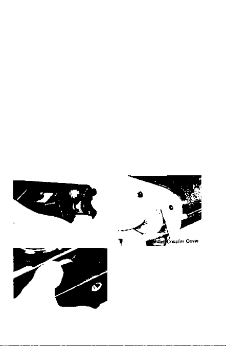
If the lens should be mounted on the
camera with the stopped-down lever locked,
correct exposure will not be obtained. In this
case, a red warning mark by the stopped-down
coupling lever inside the camera body is
visible. After removing the lens, on the lower
part of the camera body, just below the
Page 94

mirror, this stopped-down coupling lever
becomes visible, as does the red mark in the
case described above.
The Extension Tube FD 25 and FD 50
especially designed each for the FD 50mm
and FD 100mm macro lenses should be used
with full aperture metering. In this case, depth
of the field can be assured in the viewfinder
by pressing in the stopped-down lever.
Manual Aperture Control
When accessories requiring manual
aperture control are used between the camera
body and a lens, lock the lens automatic
aperture lever in the manual position before
mounting the lens.
Lock for Manual Aperture Control (1)
For manual aperture control, push the
automatic aperture lever counterclockwise
until it stops and locks. When accessories such
as extension tubes are attached to a lens that
has been set for manual control, the dia
phragm blades of the lens open or close as the
aperture ring is turned. To revert from manual
control, reset the automatic aperture lever to
its original position.
Page 95

(1)
53
Page 96

54
(2)
(3) c«
Page 97

Lock for Manual Aperture Control (2)
There are some FD lenses with the manual
lock lever requiring a different procedure for
manual control setting. With these particular
lenses, the automatic aperture lever must be
turned fully counterclockwise while the
manual lock lever is brought to the "L"
position. Once this has been done, when the
lens is mounted on the camera, the diaphragm
blades will open or close by turning the
aperture ring. To revert from manual aperture
control, reset the manual lock lever at the
position of the white dot.
Lock for Manual Aperture Control When
Using the Macrophoto Coupler (3)
In close-up photography of high mag
nification with a lens reversed on the Macro
photo Coupler, the automatic diaphragm
mechanism is not coupled, you must,
therefore, remember to close down the
diaphragm manually after having locked the
automatic aperture lever in the manual
position as explained above in (1) and (2).
Then, fix the Macrophoto Hood on the lens
mount by turning the bayonet ring.
Page 98

Changing the Lens
FD lenses incorporate a safety mechanism
to prevent the Breech-Lock ring and the dia
phragm blades from moving when the lens is
not mounted on the camera. To bypass this
safety mechanism, press the lock pin in the
top recess of the breech-Lock mount while
turning the Breech-Lock ring. Once this safety
mechanism has thus been cancelled, you can
see the diaphragm blades move when activated.
Since FD lenses have signal pins and
levers which couple with the camera body,
special care must be taken not to damage
them. One basic precaution is to always put
the lens down facing down whenever you must
change lenses.
Take notice that the following lenses
cannot be used on the AT-1 due to inter
ference with the body signal pins. Using these
lenses will cause improper meter readings
and may cause damage to the camera.
FL
19mm
FL
50mm
FL
58mm
R
35mm f/2.5 R 100mm f/3.5
f/3.5
f/1.8
f/1.2
R
50mm
R 58mm f/1.2
R
100mm f/2
f/1.8
Page 99

Lock Pin Positioning Pin
55
Page 100

EE Switch Pin Aperture Lever
Automatic
'»111!*’
Full Aperture
Signal Pin
Aperture
Signal
Lever
56
 Loading...