


Canon
FIELD SERVICE
MANUAL
CONTENTS
Chapter 1
Outline
Chapter 2 Specifications
Chapter 3
Disassembly/Reassembly and Nomenclature of
Each Section
Chapter A
Installation
Chapter 5
Replacement and Ajustment of Units
Chapter 6
Periodic Maintenance
Chapter 7
Troubleshooting
Chapter 8
Appendix
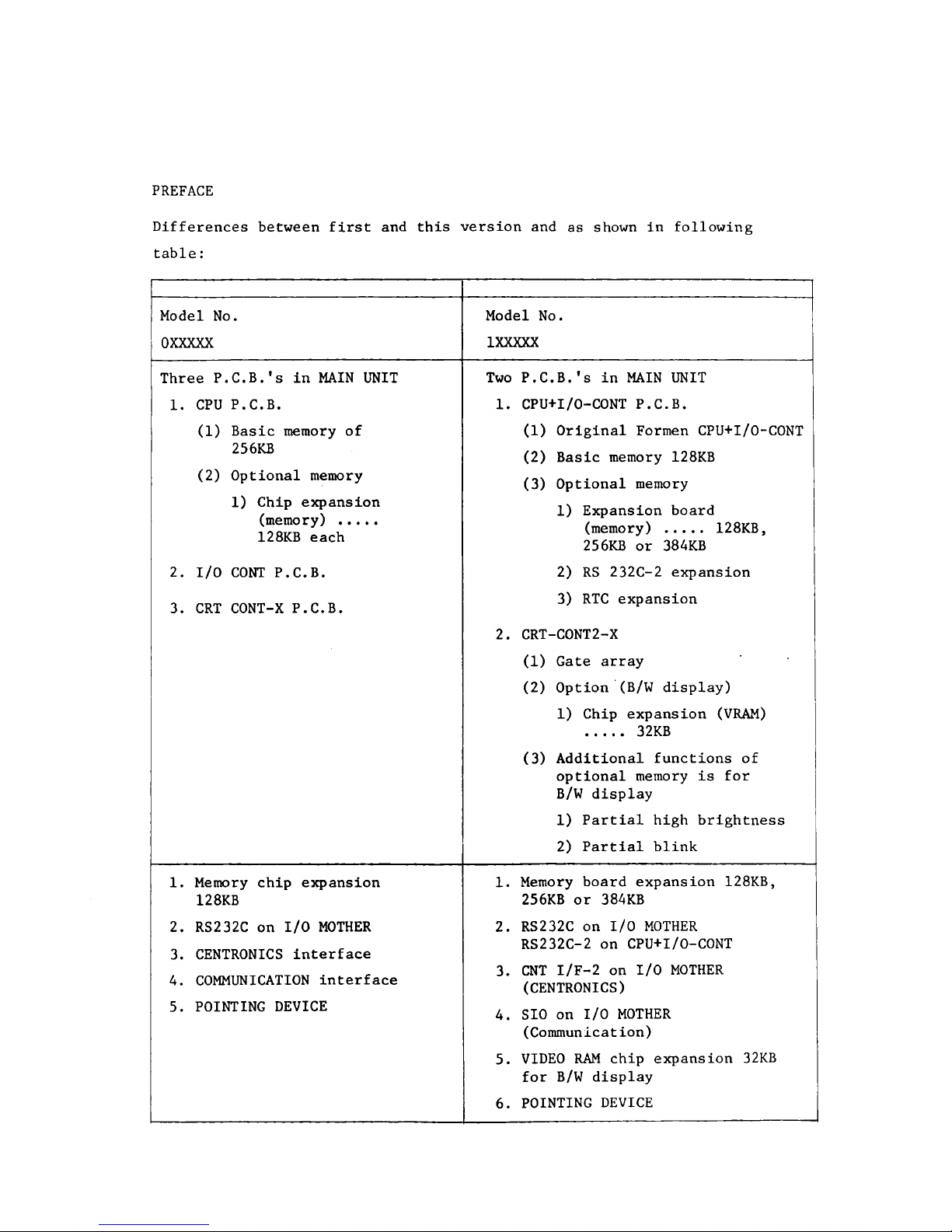
PREFACE
Differences between first and this version and as shown in following
table:
Model No.
OXXXXX
Model No.
1XXXXX
Three P.C.B.'s in MAIN UNIT
1. CPU P.C.B.
(1) Basic memory of
256KB
(2) Optional memory
1) Chip expansion
(memory)
....
128KB each
2. I/O CONT P.C.B.
3. CRT CONT-X P.C.B.
Two P.C.B.'s in MAIN UNIT
1. CPU+I/O-CONT P.C.B.
(1) Original Formen CPU+I/O-CONT
(2) Basic memory 128KB
(3) Optional memory
1) Expansion board
(memory)
....
128KB,
256KB or 384KB
2) RS 232C-2 expansion
3) RTC expansion
2. CRT-CONT2-X
(1) Gate array
(2) Option (B/W display)
1) Chip expansion (VRAM)
....
32KB
(3) Additional functions of
optional memory is for
B/W display
1) Partial high brightness
2) Partial blink
1. Memory chip expansion
128KB
2. RS232C on I/O MOTHER
3. CENTRONICS interface
4. COMMUNICATION interface
5. POINTING DEVICE
1. Memory board expansion 128KB,
256KB or 384KB
2. RS232C on I/O MOTHER
RS232C-2 on CPU+I/O-CONT
3. CNT I/F-2 on I/O MOTHER
(CENTRONICS)
4. SIO on I/O MOTHER
(Communication)
5. VIDEO RAM chip expansion 32KB
for B/W display
6. POINTING DEVICE

7. RTC
8. CURRENT LOOP
9. 5" HARD DISK
FAN
Below
CRT
Rear
Cover
FAN
Below
CRT
Rear
Cover
B/W display
None None B/W display None
1
Color
display
1
None
Color ^
display
1
UNIT
CRT UNIT B/W
, Normal brightness
UNIT
CRT UNIT B/W
. Normal brightness
. Partial high brightness
. Partial blink

Introduction
This service manual is applicable only to the specified models as shown
below. Abbreviations of models are listed in Table 1.1.1.
Model No.
f ?
□ □ □ □
Sequential numbers
Voltage No.n
1: Fixed
n: 2 120V
3 230V
A + 2A0V
5 -*• 115V
Chapter 1 Outline
1.1 Configurations
1.1.1 System configuration
1.1.2 Models
1.1.3 Software configuration
1 * 2 D e s c r i p t i o n o f F u n c t i o n s
1.2.1 CPU
1.2.2 I/O CONT (I/O Controller)
1.2.3 DISPLAY CONT (Display Controller)
1.2.4 KEYBOARD
1.2.5 5" FDD
1.2.6 8" FDD
1.2.7 PRINTER
1.2.8 I/O MOTHER (option)
1.2.9 RS232C (option)
1.2.10 CENTRONICS (option)
1.2.11 COMMUNICATION (option)
1.2.12.CURRENT LOOP (option)
1.2.13 5" HARD DISK (option)
Chapter 1 Outline
1.1 Configurations
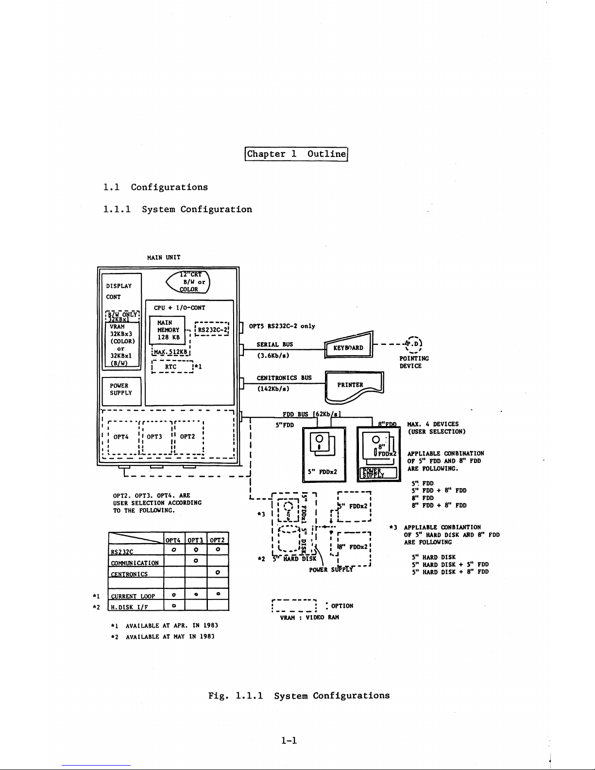
1.1.1 System Configuration
m a i n u n i t
DI SP LA Y
CONT
£
W.ON LY
m i
VRAM
32KBx3
(COLOR)
or
32KBxl
(B/W)
C
rcRr\
B/ W or )
OLOR /
PO WE R
SU PP LY
CPU ♦ I/O-CONT
MAIN
MEMOR Y
128 K B
! RS232C-2*
» S
-----
'
MAX.^12KB_|
RTC "|*I
T-
OPT4
"f r
-----
i r
-- --
-
• i I'
! I OPT3 11 OPT2
>l M
l| II
- 1. L
__________S!________
J O PTS R S232C-2 only
SERI AL BUS
t:
>
(3.6Kb/s)
CE NI TRO NI C S BU S
(142Kb/s)
OP T2. OPT3. OPT4. ARE
USER SE LECTION AC COR DIN G
TO THE FOLLOWING.
5” F DD
FDD BUS f62Kb
MAX. 4 DEVICE S
(USER S ELECTION)
APPL IABLE CONBINATION
OF 5” FDD AN D 8” FD D
ARE FOLLOWING.
I I
----
GT 1
5 3 I
FDD
*1
*2
OPT 4
OPT 3
OPT 2
RS232C
O
0
O
COMMUNICATI ON
O
CENT RONICS
O
CURR ENT LOOP
O
o
o
H.D ISK I/F
O
*3
*2
I * o ' *
l! f II
i
__V__
I *
I
■ »
*5” FDDx2 1
rf '
5*'. FDD
5" FDD + 8"
8" FDD
8" FDD + 8" FDD
I t.-.jp, | 4
1 I** I s »I 9 I
-----
1
I I !a • * * I •
18” FDDx2 *
*3
* i lO ' •
L18
5t r HARD DISK \ |
POWE R S U pPl f
I
i
•
J
APPLIABLE CONBIANTION
OF 5" HAR D D ISK AND 8" FDD
ARE FOLLOWING
5'* HA RD DISK
S'* HAR D DI SK + 5” FDD
5” HA RD DISK + 8" FDD
J . OPTIO N
m mm mm* m m mmm 4
VRAM : VIDEO RAM
*1 AVAIL ABL E AT APR. IN 1983
*2 A VAI LABL E A T MAY IN 1983
Fig. 1.1.1 System Configurations
1-1
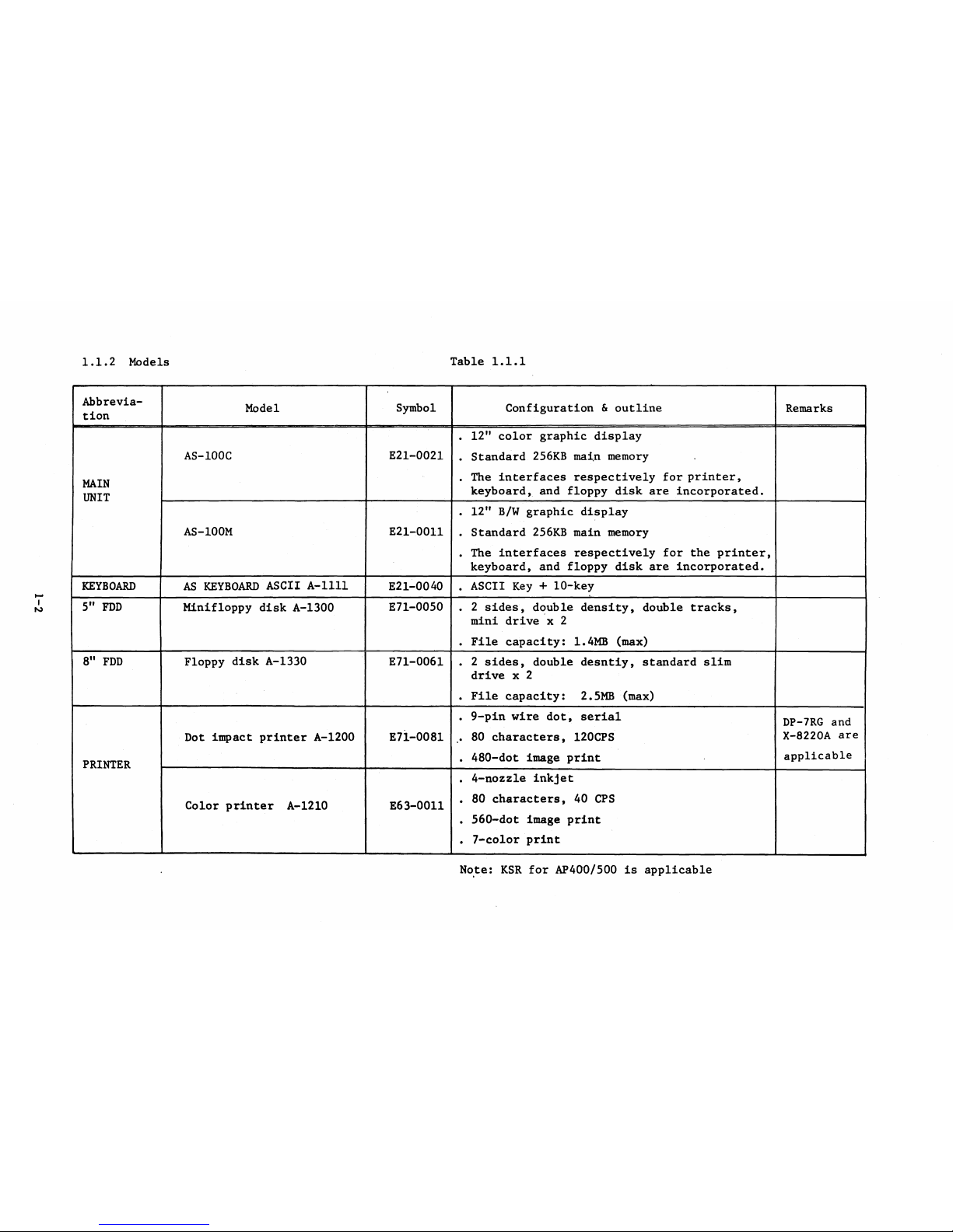
1.1.2 Models
Table 1.1.1
Abbrevia
tion
Model
Symbol
Configuration & outline
Remarks
MAIN
UNIT
AS-100C
E21-0021
. 12n color graphic display
. Standard 256KB main memory .
. The interfaces respectively for printer,
keyboard, and floppy disk are incorporated.
AS-100M
E21-0011
. 12" B/W graphic display
. Standard 256KB main memory
. The interfaces respectively for the printer,
keyboard, and floppy disk are incorporated.
KEYBOARD
AS KEYBOARD ASCII A-llll
E21-0040
. ASCII Key + 10-key
5" FDD
Minifloppy disk A-1300
E71-0050
. 2 sides, double density, double tracks,
mini drive x 2
. File capacity: 1.4MB (max)
8" FDD
Floppy disk A-1330
E71-0061
• 2 sides, double desntiy, standard slim
drive x 2
. File capacity: 2.5MB (max)
PRINTER
Dot impact printer A-1200 E71-0081
. 9-pin wire dot, serial
.. 80 characters, 120CPS
. 480-dot image print
DP-7RG and
X-8220A are
applicable
Color printer A-1210 E63-0011
. 4-nozzle inkjet
. 80 characters, 40 CPS
. 560-dot image print
. 7-color print
Note: KSR for AP400/500 is applicable
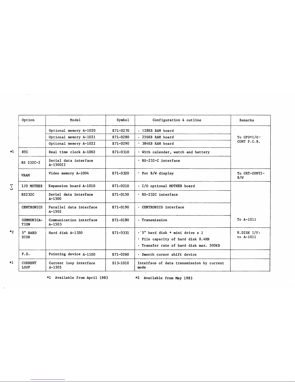
Option Model Symbol Configuration & outline
Remarks
Optional memory A-1020
E71-0270
• 128KB RAM board
To CPU+I/0-
CONT P.C.B.
Optional memory A-1021 E71-0280
• 256KB RAM board
Optional memory A-1022
E71-0290 • 384KB RAM board
RTC Real time clock A-1002
E71-0310
• With calendar, watch and battery
RS 232C-2
Serial data interface
A-1500II
• RS-232-C interface
VRAM
Video memory A-1004
E71-0320
• For B/W display To CRT-C0NT2-
B/W
I/O MOTHER Expansion board A-1010
E71-0210
• I/O optional MOTHER board
To A-1011
RS232C
Serial data interface
A-1500
E71-0150
• RS-232C interface
CENTRONICS
Parallel data interface
A-1502
E71-0190
• CENTRONICS interface
COMMUNICA
TION
Communication interface
A-1503
E71-0180
• Transmission
5" HARD
DISK
Hard disk A-1350
E71-0331
•'5" hard disk + mini drive x 1
• File capacity of hard disk 8.4MB
• Transfer rate of hard disk max. 500KB
H.DISK I/F:
to A-1011
P.D.
Pointing device A-1100
E71-0260 • Smooth cursor shift device
CURRENT
LOOP
Current loop interface
A-1505
S13-1010
Interface of data transmission by current
mode
*1 Available from April 1983
*2 Available from May 1983
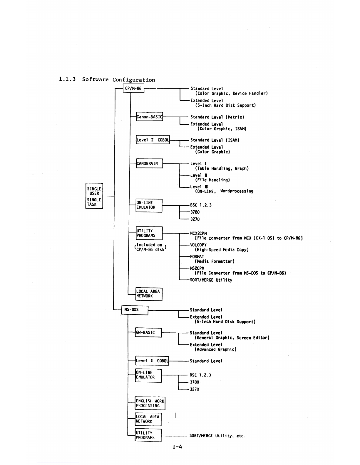
1.1.3 Software Configuration
CP/M -86
SINGLE
USER
SING LE
TASK
ON-LINE
EMULATOR '
UT ILITY
PROGRAMS
/I ncl u ded on \
'CP/M-86 d is k '
LOCAL AREA
NETWORK
MS-DOS
n j
o Act r
oW- bAb lL -
Stan da rd L evel
(C ol o r G ra p hi c, De vi ce H and le r)
------
Extended Le ve l
(5 -In c h Hard D isk S u pp o rt)
c
St an dar d Le ve l ( M at r ix )
Ext end ed L ev el
(C ol o r G ra phic, IS AM)
TZ
St an d ar d Le vel ( IS AM)
Ext end ed L ev el
(C ol o r G ra p hi c)
------
Level I
(T able H andl in g , G rap h)
— — Le ve l H
( F ile H a n dling )
------
Level m
(O N-LIN E, Wordp ro ce ss1ng
------
BSC 1 .2. 3
------
3780
------
3270
------
MCX2CPM
[ F i le C on v erter fr om MCX (CX-1 O S) to t f/M -8 6 ]
------
VOLCOPY
(H ig h-S pe e d Media C op y)
------
FORMAT
(M ed ia F or m at ter)
------
MS2CPM
( F il e Co nve rte r from MS-DOS to C P/M -8 6)
------
SORT/MERGE U t i l i t y
St and ar d Level
Extend ed L ev el
(5 -In ch H ard D i sk Su ppo rt )
St and a rd Le vel
(Gen er al G r ap h ic , Scr ee n E d i tor)
Ext end ed Leve l
(Advanced G r ap h ic )
Level 0 COBOL
St an d ar d L ev el
1-4
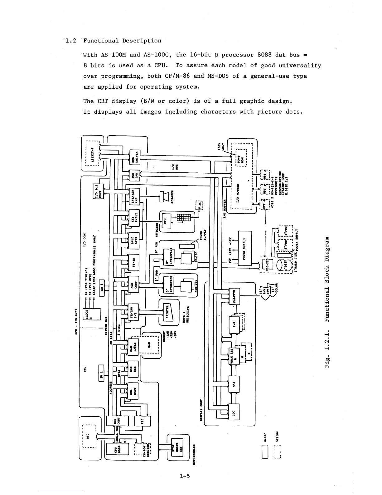
1.2 Functional Description
'With AS-100M and AS-100C, the 16-bit y processor 8088 dat bus =
8 bits is used as a CPU. To assure each model of good universality
over programming, both CP/M-86 and MS-DOS of a general-use type
are applied for operating system.
The CRT display (B/W or color) is of a full graphic design.
It displays all images including characters with picture dots.
CNl
&O
•H
fa
1-5
Functional Block Diagram
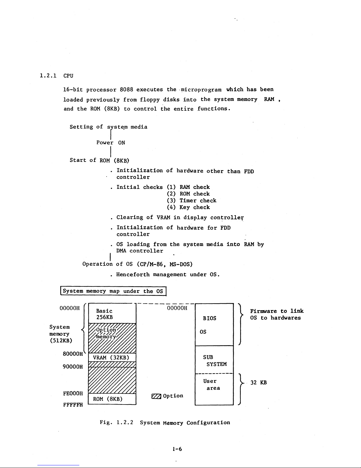
1.2.1 CPU
16-bit processor 8088 executes the microprogram which has been
loaded previously from floppy disks into the system memory RAM ,
and the ROM (8KB) to control the entire functions.
Setting of system media
Power ON
Start of ROM (8KB)
. Initialization of hardware other than FDD
• controller
. Initial checks (1) RAM check
(2) ROM check
(3) Timer check
(A) Key check
. Clearing of VRAM in display controller
. Initialization of hardware for FDD
controller
. OS loading from the system media into RAM by
DMA controller
I '
Operation of OS (CP/M-86, MS-DOS)
. Henceforth management under OS.
System memory map under the OS
00000H
System ^
memory
(512KB)
80000H'’
90000H
FE000H
FFFFFH
Basic
256KB
00000H
BIOS
/ / / S ' / / / / y Z ' / / s
y/memo ry
OS
VRAM (32KB)
SUB
' / / / / / / / / / / / / / ;
SYSTEM
i f l i f l i z
User
y / Z / / . Y / V / Y / / ,
area
ROM (8KB)
V 7 A Option
Firmware to link
OS to hardwares
32 KB
Fig. 1.2.2 System Memory Configuration
1-6
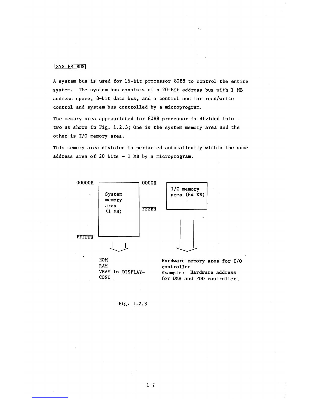
I SYSTEM BÜSl
A system bus is used for 16-bit processor 8088 to control the entire
system. The system bus consists of a 20-bit address bus with 1 MB
address space, 8-bit data bus, and a control bus for read/write
control and system bus controlled by a microprogram.
The memory area appropriated for 8088 processor is divided into
two as shown in Fig. 1.2.3; One is the system memory area and the
other is I/O memory area.
This memory area division is performed automatically within the same
address area of 20 bits - 1 MB by a microprogram.
00000H
0000H
System
memory
area
I/O memory
area (64 KB)
(1 MB)
FFFFH
FFFFFH
ROM
RAM
Hardware memory area for I/O
controller
Example: Hardware address
for DMA and FDD controller.
VRAM in DISPLAY-
CONT
Fig. 1.2.3
1-7
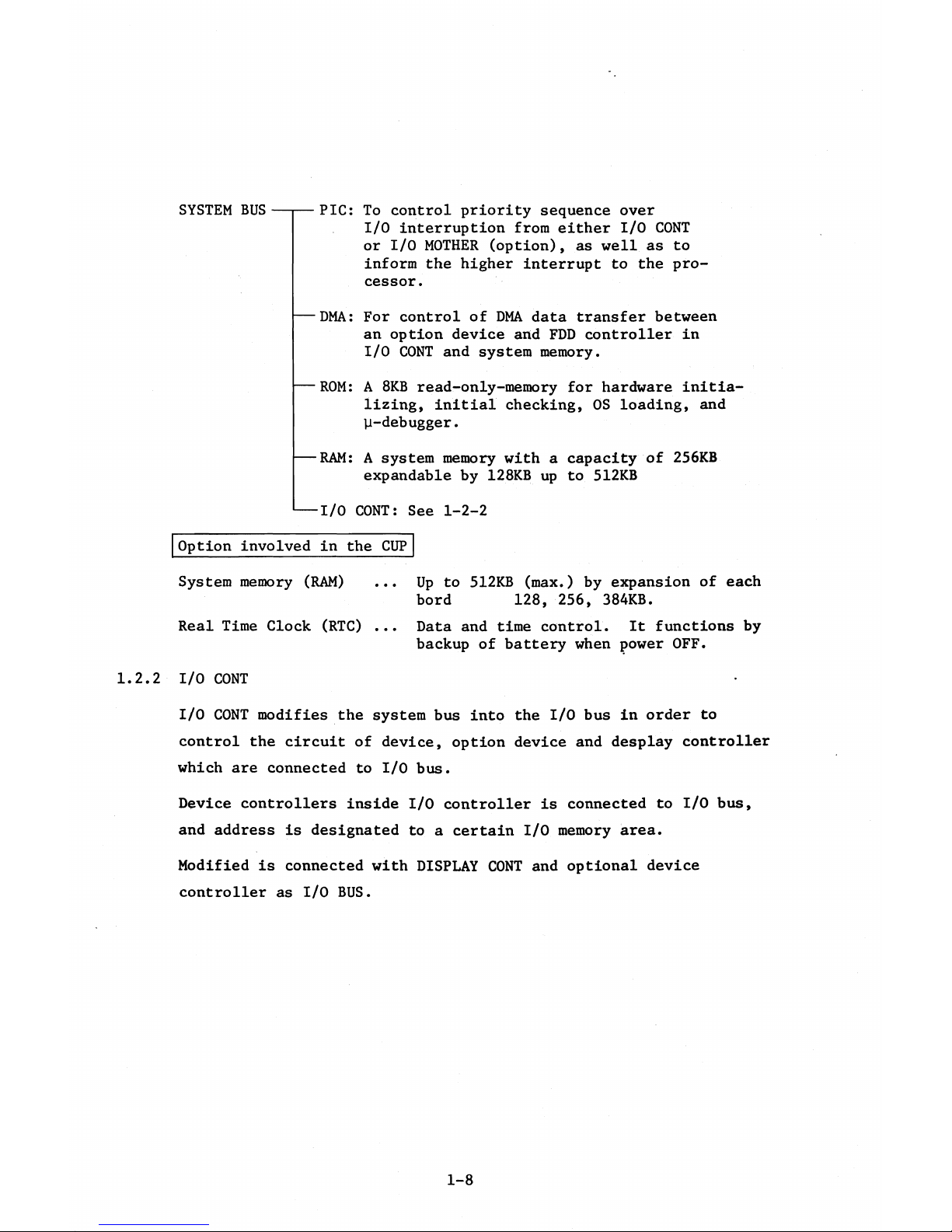
SYSTEM BUS
— PIC: To control priority sequence over
I/O interruption from either I/O CONT
or I/O MOTHER (option), as well as to
inform the higher interrupt to the pro
cessor.
— DMA: For control of DMA data transfer between
an option device and FDD controller in
I/O CONT and system memory.
— ROM: A 8RB read-only-memory for hardware initia
lizing, initial checking, OS loading, and
p-debugger.
— RAM: A system memory with a capacity of 256KB
expandable by 128KB up to 512KB
--
I/O CONT: See 1-2-2
Option involved in the CUP
System memory (RAM) ... Up to 512KB (max.) by expansion of each
bord 128, 256, 384KB.
Real Time Clock (RTC) ... Data and time control. It functions by
backup of battery when power OFF.
1.2.2 I/O CONT •
I/O CONT modifies the system bus into the I/O bus in order to
control the circuit of device, option device and desplay controller
which are connected to I/O bus.
Device controllers inside I/O controller is connected to I/O bus,
and address is designated to a certain I/O memory area.
Modified is connected with DISPLAY CONT and optional device
controller as I/O BUS.
1-8
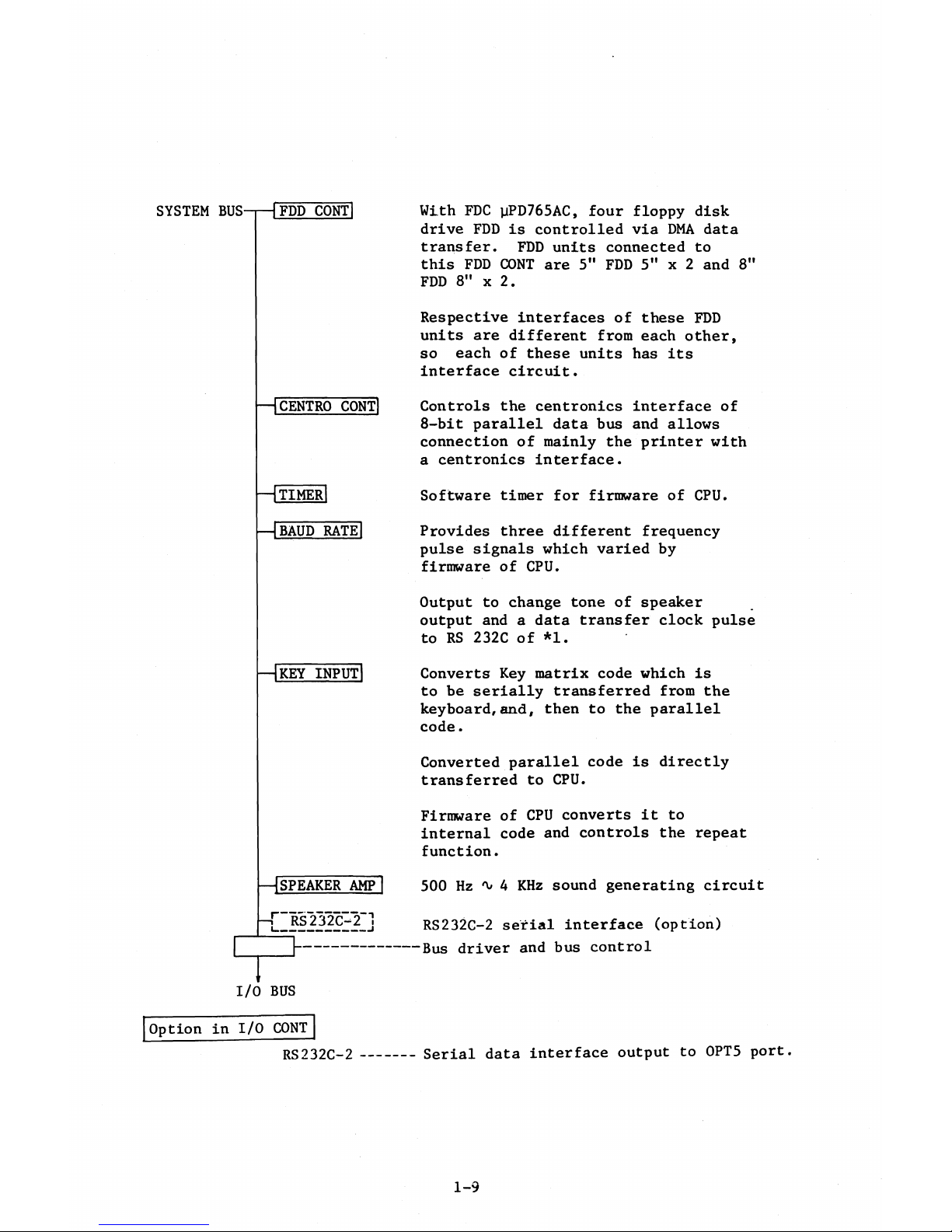
SYSTEM BUS m P CONTI With FDC yPD765AC, four floppy disk
drive FDD is controlled via DMA data
transfer. FDD units connected to
this FDD CONT are 5" FDD 5" x 2 and 8"
FDD 8" x 2.
— I CENTRO CONT]
— I TIMER
— I BAUD RATE
Respective interfaces of these FDD
units are different from each other,
so each of these units has its
interface circuit.
Controls the centronics interface of
8-bit parallel data bus and allows
connection of mainly the printer with
a centronics interface.
Software timer for firmware of CPU.
Provides three different frequency
pulse signals which varied by
firmware of CPU.
— I KEY INPUT
Output to change tone of speaker
output and a data transfer clock pulse
to RS 232C of *1.
Converts Key matrix code which is
to be serially transferred from the
keyboard,and, then to the parallel
code.
Converted parallel code is directly
transferred to CPU.
— I SPEAKER AMP I
— T_ RS232C-T]
I/O BUS
Firmware of CPU converts it to
internal code and controls the repeat
function.
500 Hz 4 KHz sound generating circuit
RS232C-2 serial interface (option)
Bus driver and bus control
Option in I/O CONT
RS232C-2
------
Serial data interface output to 0PT5 port.
1-9
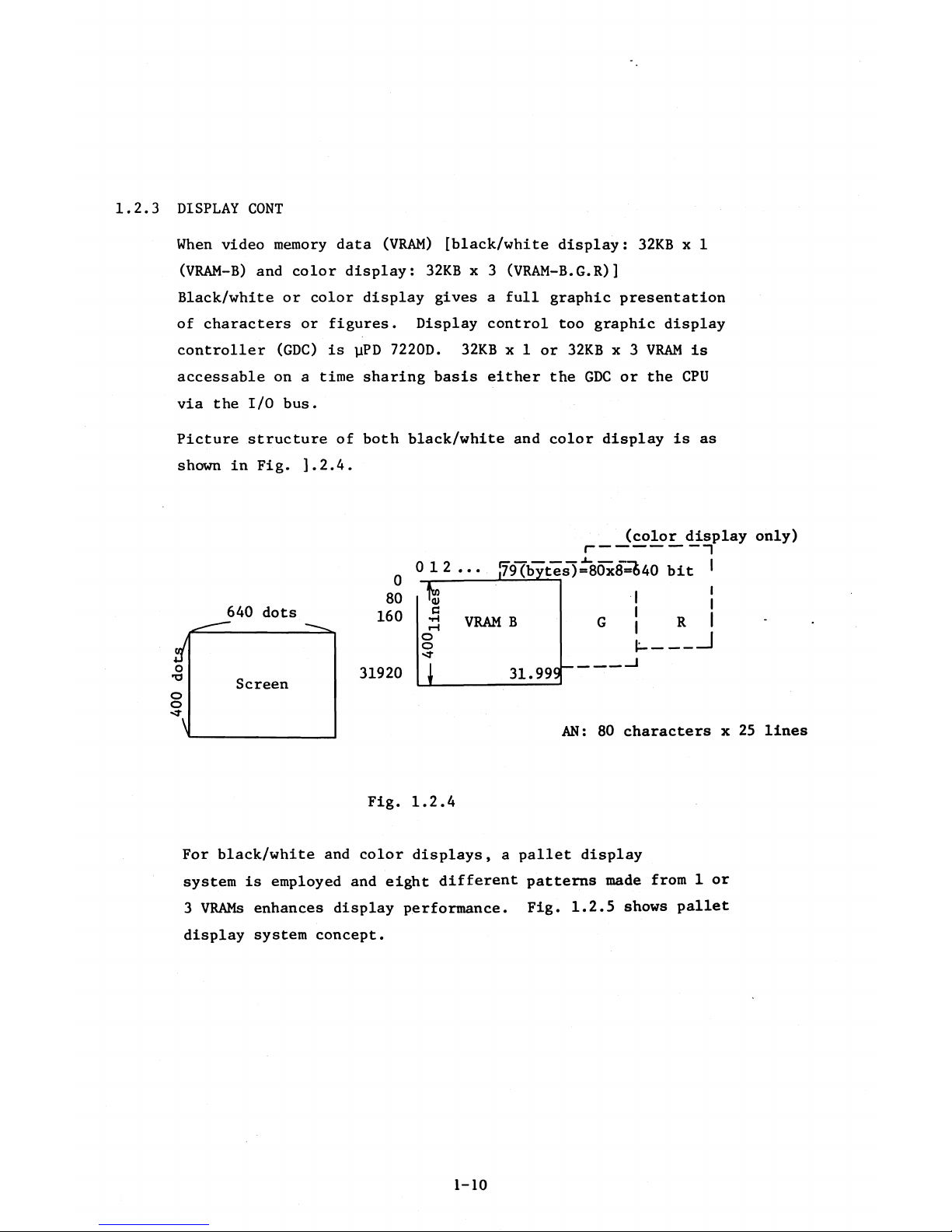
1.2.3 DISPLAY CONT
When video memory data (VRAM) [black/white display: 32KB x 1
(VRAM-B) and color display: 32KB x 3 (VRAM-B.G.R)]
Black/white or color display gives a full graphic presentation
of characters or figures. Display control too graphic display
controller (GDC) is yPD 7220D. 32KB x 1 or 32KB x 3 VRAM is
accessable on a time sharing basis either the GDC or the CPU
via the I/O bus.
Picture structure of both black/white and color display is as
shown in Fig. ].2.4.
(color display only)
i--------------1
)=80x8=&40 bit '
AN: 80 characters x 25 lines
Fig. 1.2.4
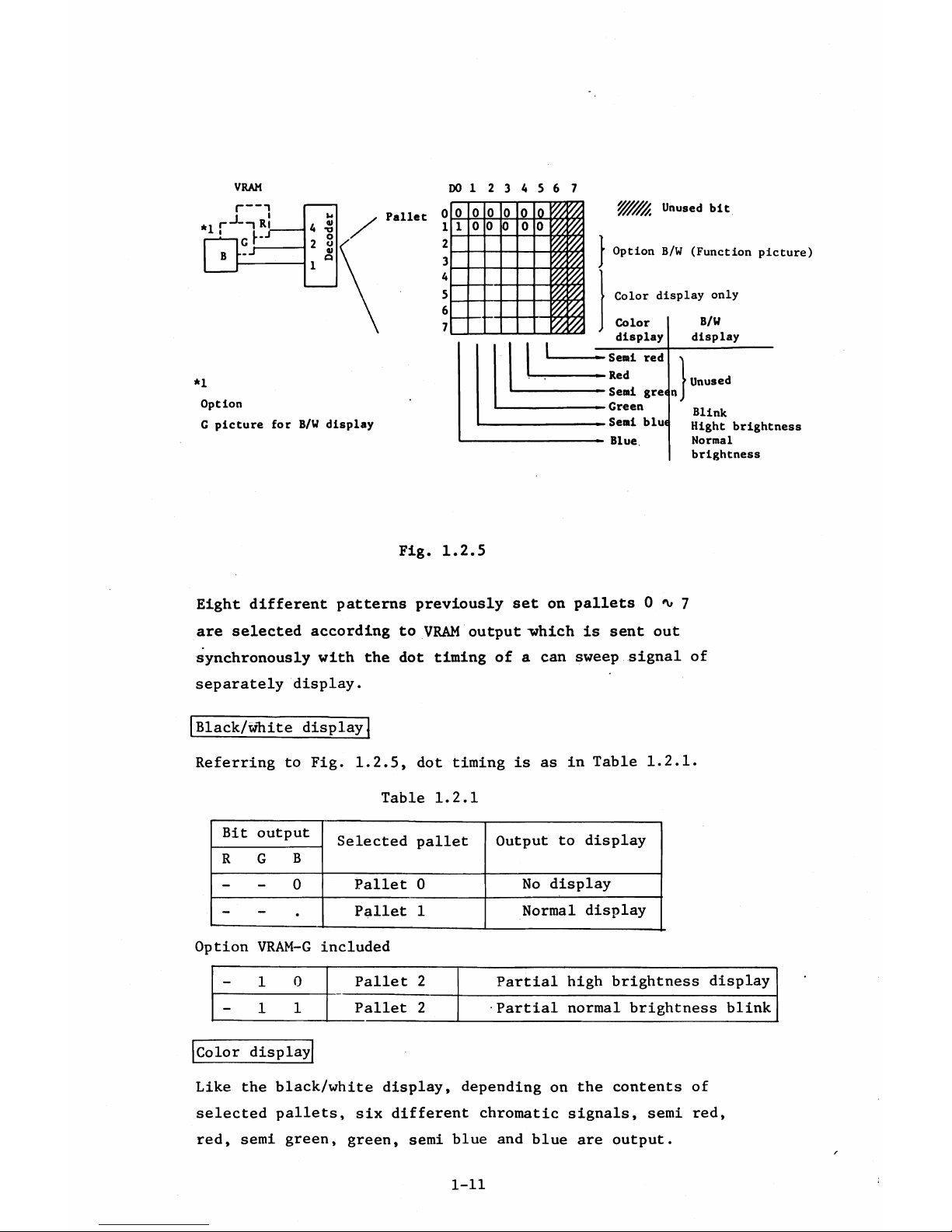
For black/white and color displays, a pallet display
system is employed and eight different patterns made from 1 or
3 VRAMs enhances display performance. Fig. 1.2.5 shows pallet
display system concept.
I
t
--
R I
0 12... *79 (bytl
640 dots
31920
1-10
VRAM
D01234567
*1
Option
G picture for B/W display
Fig. 1.2.5
Eight different patterns previously set on pallets 0 <\» 7
are selected according to VRAM output -which is sent out
synchronously with the dot timing of a can sweep signal of
separately display.
Black/white display
Referring to Fig. 1.2.5, dot timing is as in Table 1.2.1.
Table 1.2.1
Bit
output
Selected pallet
Output to display
R
G B
-
- 0
Pallet 0
No display
-
~ . Pallet 1
Normal display
Option VRAM-G included
- 1 0
Pallet 2 Partial high brightness display
- 1 1
Pallet 2
•Partial normal brightness blink
Color display
Like the black/white display, depending on the contents of
selected pallets, six different chromatic signals, semi red,
red, semi green, green, semi blue and blue are output.
1-11
For a half-tone chromatic display, two chromatic signals of a
primary color and a semi color are required but no combination
is available between a primary and a semi color of same color
type.
Therefore, a display with 27 different colors is possible as shown
in Fig. 1.2.6.
— Sequence of color combination
27 combinations of 3 colors are
possible as indicated by the solid
line.
Referring to Fig. 1.2.5, eight different patterns are.selected in
advance on the pallets; therefore, eight colors be selected
differently from the 27 colors.
Option in DISPLAY CONT
VRAM
....
Optional chip of 32 KB x 1 for B/W display
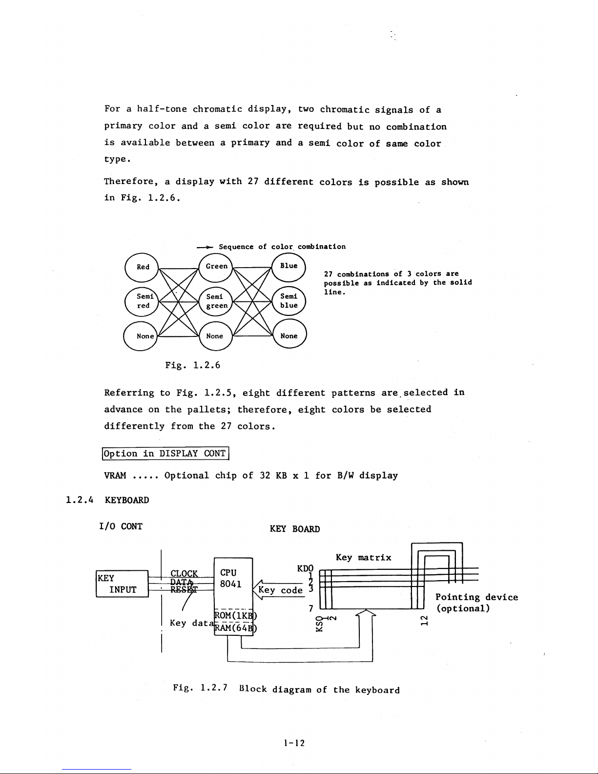
1.2.A KEYBOARD
I/O CONT KEY BOARD
KEY
INPUT
CLOCK
-DAT^
-RESi
ROM(1KB)
Key dataRAM(64B)
CPU
80A1
Key matrix
KDO
/i
-------
vKey code
Pointing device
(optional)
O H CM
m
Fig. 1.2.7 Block diagram of the keyboard
1-12
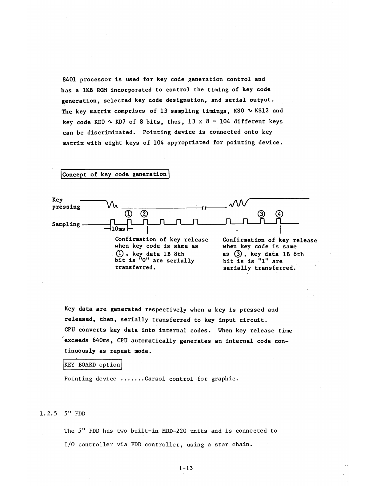
8401 processor Is used for key code generation control and
has a 1KB ROM incorporated to control the timing of key code
generation, selected key code designation, and serial output.
The key matrix comprises of 13 sampling timings, KSO 'v KS12 and
key code KDO 'V KD7 of 8 bits, thus, 13 x 8 » 104 different keys
can be discriminated. Pointing device is connected onto key
matrix with eight keys of 104 appropriated for pointing device.
Concept of key code generation
Key -
pressing
Sampling
Confirmation of key release
when key code is same as
( D , key data IB 8th
bit is "0" are serially
transferred.
©
n _
I
Confirmation of key release
when key code is same
as (3) , key data IB 8th
bit is is "l" are _
serially transferred.
Key data are generated respectively when a key is pressed and
released, then, serially transferred to key input circuit.
CPU converts key data into internal codes. When key release time
exceeds 640ms, CPU automatically generates an internal code con
tinuously as repeat mode.
KEY BOARD option
Pointing device
......
Carsol control for graphic.
1.2.5 5" FDD
The 5" FDD has two built-in MDD-220 units and is connected to
I/O controller via FDD controller, using a star chain.
1-13
FDD Controller also drives the 8" FDD (YD-180 x 2) with same bus
line; therefore, 5" FDD incorporates an interface circuit con
sisting of VFO circuit, condition generator circuit, bus driver/
receiver circuit for common application of one same bus.
Power supply is provided from main unit separately from signal
bus.
1.2.6 8'! FDD
Except for the following, 8" FDD is the same as 5" FDD
(MDD220 x 2).
Drive YD-180 x 2 (daisy chain)
Interface circuit VFO circuit
Power source Built-in
1.2.7 PRINTER
Refer to PRINTER TECHNICAL GUIDE.
1.2.8 I/O MOTHER (option)
The I/O MOTHER is for optional interface and devices to be connected
to I/O bus. I/O mother keeps a 96KB system memory area for optional
use and a 3-port (0PT2, 0PT3, 0PT4) for optional interface addressed
in I/O memory area.
The following optional device and interface are connected to I/O
MOTHER.
o System memory area (90000H - A7FFFH) ... Option use
o I/O memory area
I/O memory area is normally allocated to meet the respective port
select and status read, for optional interface-use by three ports.
1-14
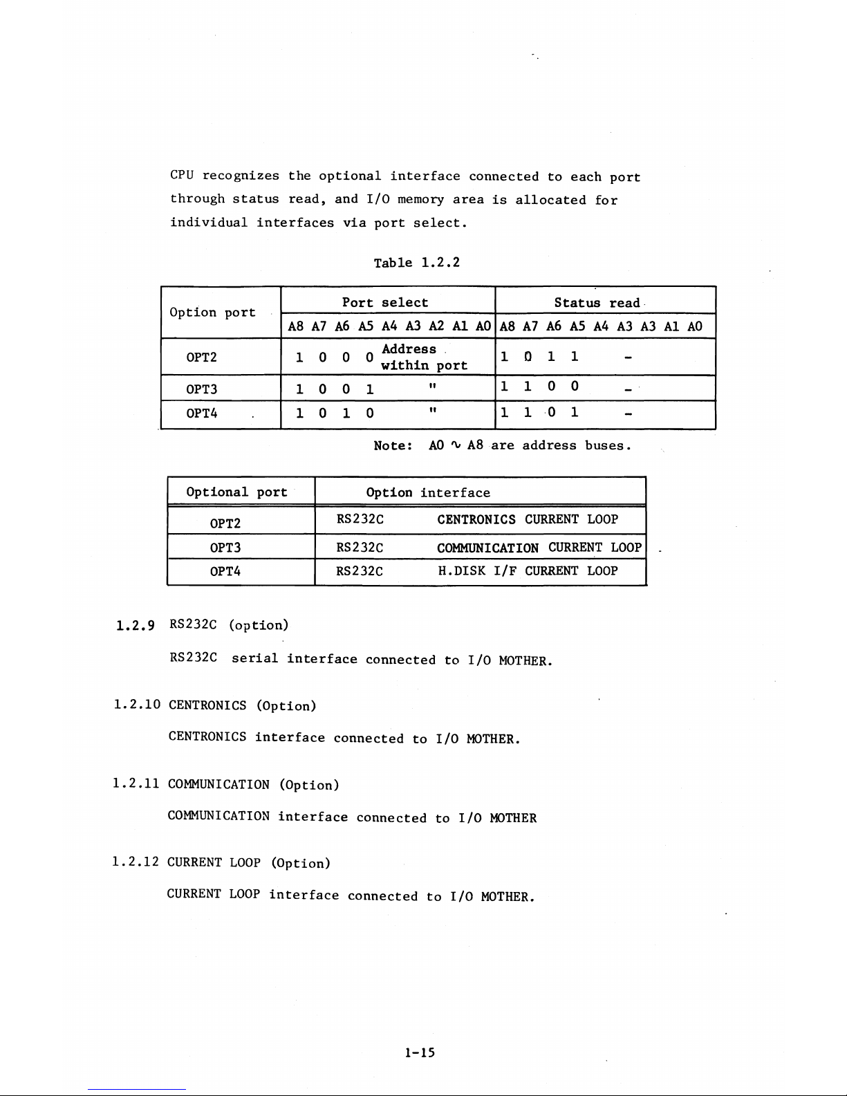
CPU recognizes the optional interface connected to each port
through status read, and I/O memory area is allocated for
individual interfaces via port select.
Table 1.2.2
Option port
Port select
Status read
A8 A7 A6 A5 A4 A3 A2 A1 AO
A8 A7 A6 A5 A4 A3 A3 Al A0
OPT 2
1 0 0 0 Addre8s
•L u u within port
10 1 1 -
OPT3 1 0 0 1 "
1 1 0 0 _
OPT4 . 10 1 0 "
1 1 0 1 -
Note: AO 'v A8 are address buses.
Optional port
Option interface
0PT2
RS232C CENTRONICS CURRENT LOOP
0PT3 RS232C
COMMUNICATION CURRENT LOOP
0PT4
RS232C
H.DISK I/F CURRENT LOOP
1.2.9 RS232C (option)
RS232C serial interface connected to I/O MOTHER.
1.2.10 CENTRONICS (Option)
CENTRONICS interface connected to I/O MOTHER.
1.2.11 COMMUNICATION (Option)
COMMUNICATION interface connected to I/O MOTHER
1.2.12 CURRENT LOOP (Option)
CURRENT LOOP interface connected to I/O MOTHER.
1-1 5
1.2.13 5" HARD DISK (option)
5" HARD DISK consists of a M4863 hard disk, a MDD220 and power
supply unit.
M4863 connects to H.DISK interface circuit which provides in
MAIN UNIT through the disk controller built-in M4863.
MDD-220 connects to FDD CONT through 5"FDD interface circuit.
1-16
Chapter 2 Specifications
2 . 1
MAIN UNIT
2 . 2
5" FDD
2.3
8" FDD
2.4
KEYBOARD
2.5
PRINTER
2.6
Option
I n t e r f a c e
2 . 7
O p t i o n ( O t h e r s )
2.8 General Specification
Chapter 2 Specifications
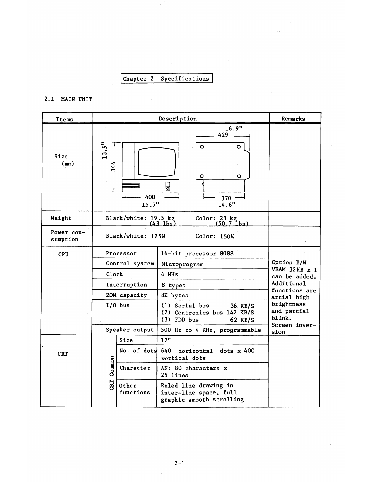
2.1 MAIN UNIT
Items
Size
(mm)
Description
«A
0
C O
<r
<o
400
15.7"
16.9"
429
__
370 -
14.6"
Remarks
Weight
Black/white: 19.5 k;j.y.0 kg
(431bs)
Color: 23 k;
kg
(50.7 lbs)
Power con
sumption
Black/white: 125W
Color: 150W
CPU
Processor
Control system
Clock
Interruption
ROM capacity
I/O bus
Speaker output
16-bit processor 8088
Microprogram
4 MHz
8 types
8K bytes
(1) Serial bus 36. KB/S
(2) Centronics bus 142 KB/S
(3) FDD bus 62 KB/S
500 Hz to 4 KHz, programmable
Size
12"
No. of dots
640 horizontal dots x 400
vertical dots
Character
AN: 80 characters x
25 lines
Other
functions
Ruled line drawing in
inter-line space, full
graphic smooth scrolling
Option B/W
VRAM 32KB x 1
can be added.
Additional
functions are
artial high
brightness
and partial
blink.
Screen inver
sion
CRT
o
u
04
O
2-1
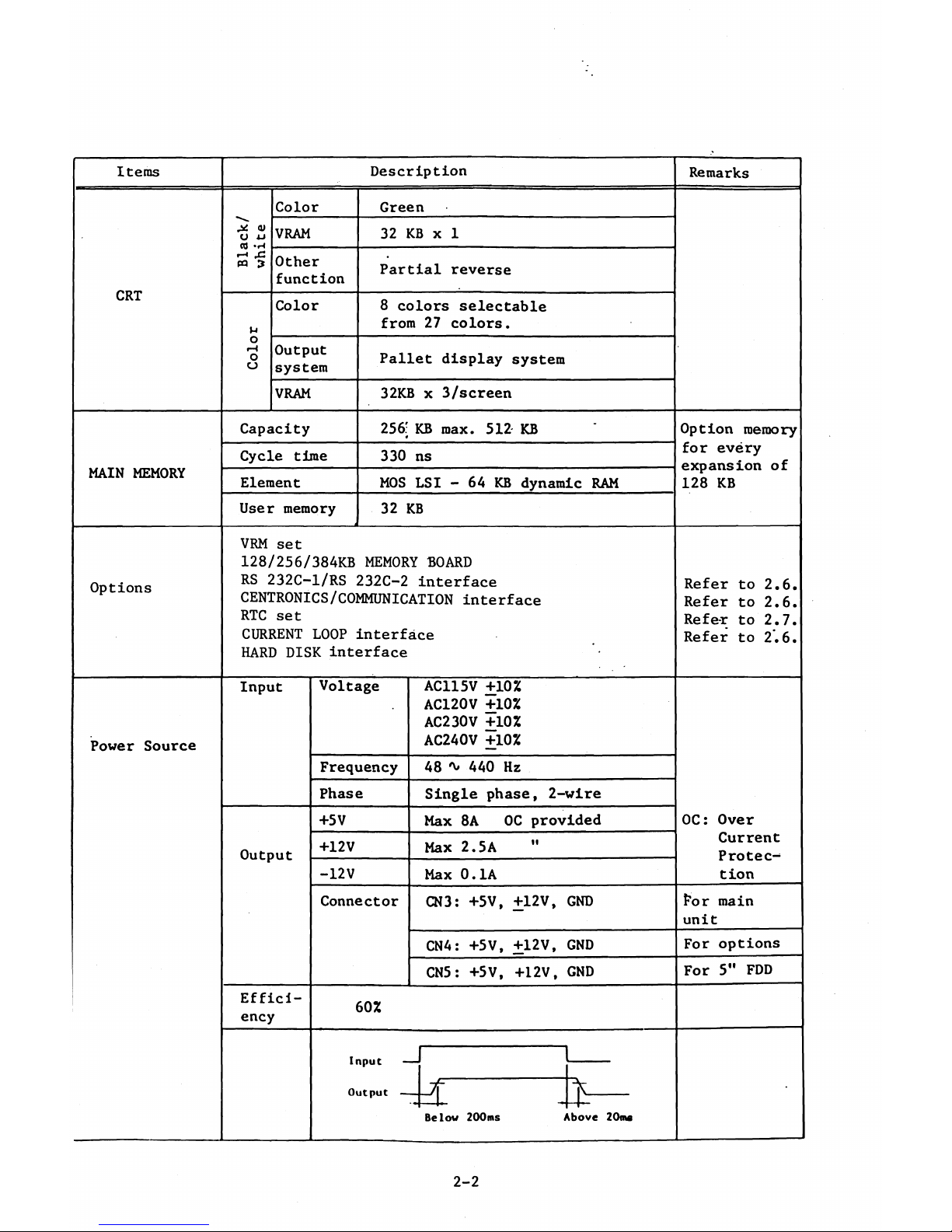
Items
Description
Remarks
Color Green
Black/
white
VRAM 32 KB x 1
CRT
Other
function
Partial reverse
Color
8 colors selectable
from 27 colors.
O
H
O
CJ
Output
system
Pallet display system
VRAM
32KB x 3/screen
Capacity
256: KB max. 512 KB ' Option memory
MAIN MEMORY
Cycle time
330 ns
for every
expansion of
128 KB
Element
MOS LSI - 64 KB dynamic RAM
User memory
32 KB
Options
VRM set
128/256/384KB MEMORY BOARD
RS 232C-1/RS 232C-2 interface
Refer to 2.6.
CENTRONICS/COMMUNICATION interface
Refer to 2.6.
RTC
set
Refe-r to 2.7.
CURRENT LOOP interface
HARD DISK interface
Refer to 2.6.
Power Source
Input
Output
Effici
ency
Voltage
Frequency
Phase
+5V
+12V
-12V
Connector
AC115V +10%
AC120V +10%
AC230V +10%
AC240V +10%
48 * 440 Hz
Single phase, 2-wire
Max 8A OC provided
Max 2.5A
Max 0.1A
CN3: +5V, +12V, GND
CN4: +5V, +12V, GND
CN5: +5V, +12V, GND
60%
X
B elo v 20 0 m s
OC: Over
Current
Protec
tion
For main
unit
For options
For 5" FDD
Ab ove 20ms
2-2
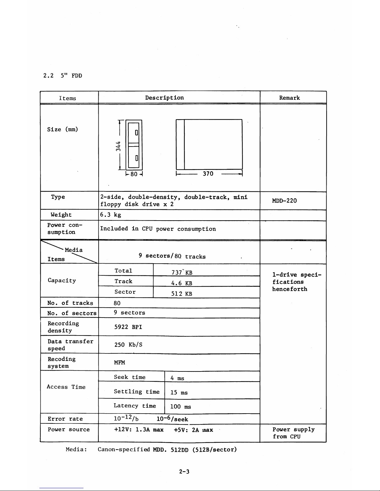
2.2 5" FDD
Media: Canon-specified MDD. 512DD (512B/sector)
2-3

2.3 8" FDD
Item
Size (mm)
<r
cn
i
□
— 180—
Description
Remarks
Type
2-side,
drive x
double-density,
2
slim type floppy disk
Weight
Power con
sumption
Capacity
15 kg
50W
Total
Track
Sector
1.25MB
8KB
1024B
No. of tracks 77
No. of sectors 8
Recording
density
6816 BPI
Data transfer
speed
500 Kb/s
Recording
system
MFM
Access Time
Seek time
3ms
Settling time
15ms
Latency time
83ms
Error rate
10-12/B
10-6/SEEK
Power source
+24V: 3.0A
+5V: 3.6A
YD-180
1-drive speci
fications
henceforth
In case of
media given in
format of
1024B/sector
Built-in
Media: Canon specified MDD-256D (256B/sector)
2-4
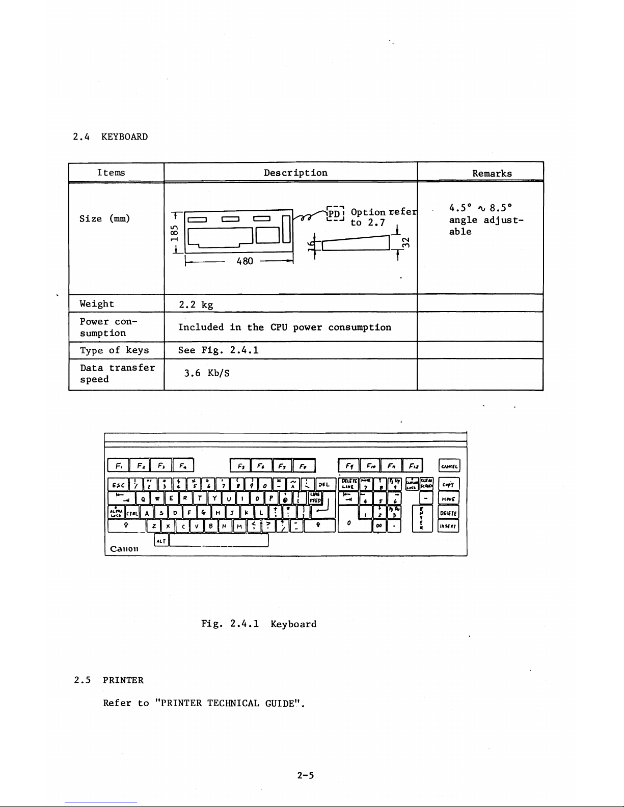
2.4 KEYBOARD
Items
Description
Remarks
Size (mm)
- ^ - J P D J Option refer
to 2,7 .
4-i— — n s
4.5° *\, 8.5°
angle adjust
able
T"
m
00
i—l
c=] c=D c=i p
L
'
-
1 j
a on - T-
: 1 T
—
-
-----
H OU *
-
Weight
2.2 kg
Power con
sumption
Included in the CPU power consumption
Type of keys
See Fig. 2.4.1
Data transfer
speed
3.6 Kb/S
Fig. 2.4.1 Keyboard
2.5 PRINTER
Refer to "PRINTER TECHNICAL GUIDE".
2-5
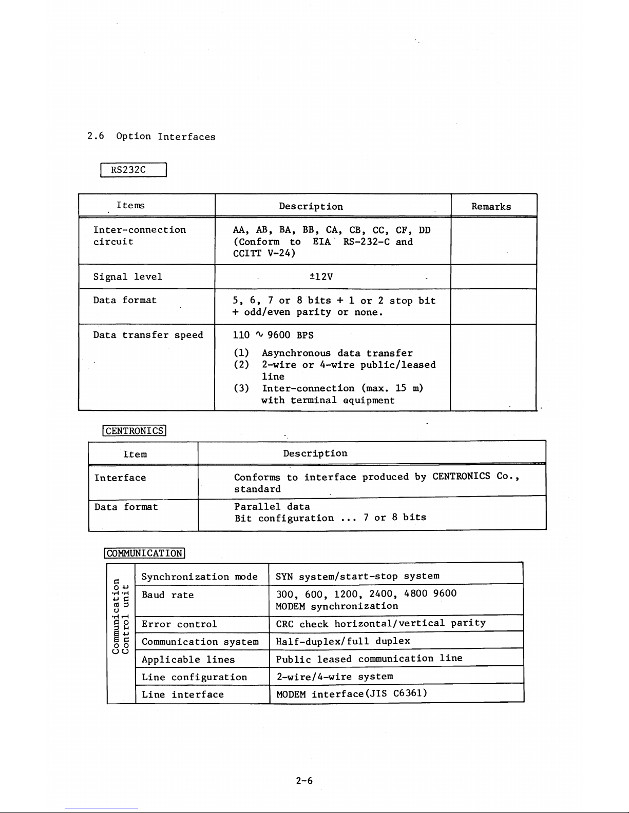
2.6 Option Interfaces
RS232C
Items
Description
Remarks
Inter-conne c t ion
circuit
AA, AB, BA, BB, CA, CB, CC, CF, DD
(Conform to EIA RS-232-C and
CCITT V-24)
Signal level ±12V -
Data format
5,6, 7 or 8 bits + 1 or 2 stop bit
+ odd/even parity or none.
Data transfer speed
110 ^ 9600 BPS
(1) Asynchronous data transfer
(2) 2-wire or 4-wire public/leased
line
(3) Inter-connection (max, 15 m)
with terminal equipment
1CENTRONICS!
Item
Description
Interface
Conforms to interface produced by CENTRONICS Co.,
standard
Data format
Parallel data
Bit configuration ... 7 or 8 bits
I c o m m u n i c a t i o n !
e
O
•H *H
u C
cü a
o
Synchronization mode
SYN system/start-stop system
Baud rate
300, 600, 1200, 2400, 4800 9600
MODEM synchronization
•H tH
c o
3 M
Error control
CRC check horizontal/vertical parity
6 -u
g a
o o
Communication system
Half-duplex/full duplex
a u
Applicable lines
Public leased communication line
Line configuration
2-wire/4-wire system
Line interface
MODEM interface(JIS C6361)
2-6

I CURRENT LÖÖPl
Available soon
2-7