

Canon 580EX II User Manual
COPY
MANUAL DE INSTRUCCIONES
EnglishFrançaisEspañol
INSTRUCTION MANUAL
MODE D’EMPLOI

COPY
English

Thank you for purchasing a Canon product.
COPY
The Canon Speedlite 580EX II is an EOS-dedicated, high-output flash
unit automatically compatible with E-TTL II, E-TTL, and TTL autoflash.
It can serve as an on-camera flash as well as a master unit or a slave
unit in a wireless, multiple-Speedlite system. It has the same dust- and
water-resistance as EOS-1D series cameras.
Read this instruction manual while also referring to your
camera’s instruction manual.
Before using the Speedlite, read this instruction manual and your camera’s
instruction manual to familiarize yourself with the Speedlite operations.
The basic operation is as easy as with normal AE shooting.
When the 580EX II is attached to an EOS camera, almost all automatic
exposure control for flash photography is handled by the camera.
It is almost the same as using the camera’s built-in flash if it has one. You can
think of the 580EX II as a built-in, high-output flash, but attached externally.
It becomes automatically compatible with the camera’s flash
metering mode (E-TTL ll, E-TTL, and TTL).
In accordance with the camera’s flash control system, the Speedlite controls
the flash automatically in the respective flash metering mode:
1. E-TTL II autoflash (evaluative flash metering with preflash reading/lens
distance information)
2. E-TTL autoflash (evaluative flash metering with preflash reading)
3. TTL autoflash (off-the-film metering for real-time flash metering)
Regarding the camera’s available flash metering modes, refer to the
“External Speedlite” specification in the “Specifications” of your
camera’s instruction manual.
The camera instruction manual’s chapter on flash photography will refer
to cameras having flash metering modes 1 or 2 as a Type-A camera
(compatible with E-TTL II or E-TTL). And cameras having flash
metering mode 3 (compatible with only TTL) are called Type-B
cameras.
* This instruction manual assumes that you are using the Speedlite
with a Type-A camera.
For Type-B cameras, see page 55.
2
Contents
COPY
1 Getting Started and Basic Operation ................................ 7
2 Using Flash........................................................................ 13
3 Wireless Flash ................................................................... 33
4 Reference........................................................................... 47
Conventions Used in this Manual
The <9> symbol in the text refers to the Select Dial.
The <8> symbol in the text refers to the Select/Set button.
The symbol in the text refers to a Custom Function.
The operation procedures in this instruction manual assume that both
the camera and Speedlite’s power switches are ON.
Icons used in the text to indicate the respective buttons, dials, and
settings match the same icons found on the camera and Speedlite.
The (4) / (0) / (3) icons indicate that the respective function
remains in effect for 4 sec., 6 sec., or 16 sec. after you let go of the
button.
Reference page numbers are indicated by (p.**).
This instruction manual uses the following alert symbols:
: The Caution symbol indicates a warning to prevent shooting
problems.
: The Note symbol gives supplemental information.
3

Nomenclature
COPY
Flash head/
Wireless
transmitter
Catchlight panel (retracted) (p.19)
Built-in wide panel
(retracted) (p.20)
Wireless sensor
AF-assist beam emitter
(p.49)
External metering
sensor (p.30)
Mounting foot (p.9)
Mini stand pocket
4
Locking pin (p.9)
Case
Contacts
Contact cover
External power
source socket
PC terminal
Bracket mounting
hole
Mini stand
Shoe
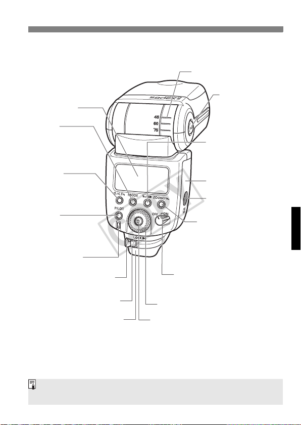
LCD panel
COPY
D>
<
Flash mode/
Slave setting button
(p.11, 22, 24/45, 46)
* <
A>
LCD panel illumination/
Custom Function setting
button (p.6/27)
<
J>
Pilot lamp/Test firing/
Wireless slave power
ON button (p.10/38)
Flash exposure
confirmation lamp (p.11)
Mounting foot’s
lock lever (p.9)
Lock-release button (p.9)
Dust- and water-resistant
adapter
Power switch (p.10)
L> : Power off
<
K> : Power on
<
9
<
> Select Dial
8
> Select/Set button
* <
Bounce angle
<
z>
Bounce lock release
button (p.18)
<
E>
High-speed sync
(FP flash)/Shutter curtain
synchronization button
(p.17/26)
Battery compartment
cover (p.8)
Battery compartment
lock lever (p.8)
<
G>
Zoom button/
Wireless selector/
Wireless set button
(p.20/36, 39, 40, 41, 42, 45)
Asterisked buttons have functions which remain active for 8 sec. after you
press and let go of the button. The <B> illumination lasts for 12 sec.
5
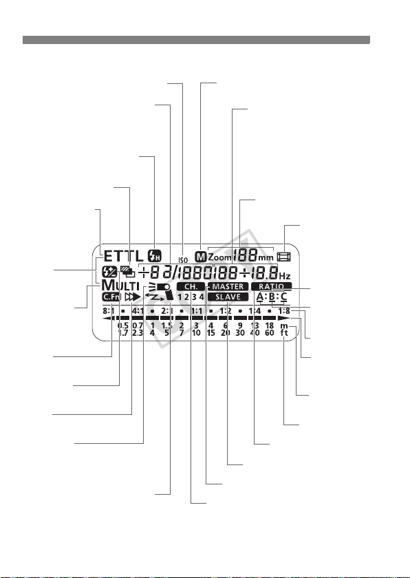
LCD Panel
COPY
9> ISO speed
<
Manual flash output level
Flash exposure
compensation amount
FEB compensation amount
<
c> High-speed sync
(FP flash)
<
g> FEB
<
8/a/b>
Auto external
metering/
E-TTL (ll)/
TTL autoflash
8q>
<
Manual external
metering
<
q/p>
Manual flash/Multi
(Stroboscopic)
flash
<u>
Custom Function
f> Flash
<
exposure compensation
r>
<
Second-curtain sync
Firing mode
Master flash ON : W
Master flash OFF : Y
Slave flash : X
<
V> Flash bounce indicator
(Blinks for 7 down)
To illuminate the LCD panel, press the <B> button.
The items actually displayed depend on the current settings.
<
d> Manual zoom
Aperture
FEB status
Stroboscopic flash count
Stroboscopic flash frequency
Manual flash 1/3-stop
increment indicator
Custom Function No.
Custom Function setting
<
x> Slave
M> Master
<
w> Channel
<
Zoom focal length
y> Flash ratio
<
<
s> Auto zoom
for image size
Slave ID
Slave ID
underscore
Flash ratio
Flash range
scale/Flash
ratio scale
Indicator
(meters)
Indicator (feet)
6
Getting Started and
COPY
Basic Operation
Installing the Batteries ............................................ 8
Attaching to the Camera......................................... 9
Turning on the Power Switch................................ 10
Fully Automatic Flash Shooting............................. 11
Using E-TTL II and E-TTL Autoflash in the
Shooting Modes.................................................... 12
Cautions for firing continuous flashes
To avoid overheating and degrading the flash
head, do not fire more than 20 continuous
flashes. After 20 continuous flashes, allow a rest
time of at least 10 min.
If you fire more than 20 continuous flashes and
then fire more flashes in short intervals, the
inner overheating prevention function may be
activated to make the recycling time about 8 to
20 sec. If this occurs, allow a rest time of about
15 min. and the flash will then return to normal.
7
Installing the Batteries
COPY
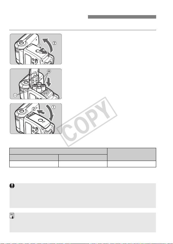
Install four size-AA batteries.
Open the cover.
1
Use your thumb to press the battery
compartment lock lever, then slide it
as shown by the arrow c to open the
cover.
Install the batteries.
2
Make sure the + and – battery
contacts are properly oriented as
shown in the compartment.
Close the cover.
3
Close the battery compartment cover
and slide it as shown by the arrow.
X When the cover clicks in place, it will
be locked.
Recycling Time and Flash Count (with size-AA alkaline batteries)
Recycling Time
Quick Flash Normal Flash
Approx. 0.1 - 2.5 sec. Approx. 0.1 - 5 sec. Approx. 100 - 700
Based on new size-AA alkaline batteries and Canon’s testing standards.
Quick flash enables a flash to be fired before flash-ready (p.10).
Using size-AA batteries other than the alkaline type may cause improper
battery contact due to the irregular shape of the battery contacts.
If you change the batteries after firing many flashes continuously, be
aware that the batteries might be hot.
Use a new set of four batteries of the same brand. When replacing the
batteries, replace all four at one time.
Size-AA Ni-MH or lithium batteries can also be used.
8
Flash Count

Attaching to the Camera
COPY
Attach the Speedlite.
1
Slip the Speedlite’s mounting foot into
the camera’s hot shoe all the way.
Secure the Speedlite.
2
On the mounting foot, slide the lock
lever to the right.
X When the lock lever clicks in place, it
will be locked.
Detach the Speedlite.
3
While pressing the lock-release
button, slide the lock lever to the left
and detach the Speedlite.
9

Turning on the Power Switch
COPY
Set the power switch to <K>.
1
X The flash recycling starts.
Check that the flash is ready.
2
The pilot lamp will first turn green (ready
for quick flash), then red (flash ready).
Pressing the pilot lamp will fire a test
flash.
About Quick Flash
Quick flash enables a flash to be fired before flash-ready, when the pilot
lamp is still green.
Although the Guide No. will be 1/6 to 1/2 that of the full output, quick flash
is effective for near subjects and when you want a shorter recycle time.
Set the drive mode to single shooting. Quick flash cannot be used in the
continuous shooting, FEB, manual flash, and stroboscopic flash modes.
Quick flash can also be used during continuous flash shooting.
(C.Fn-06 → p.27)
About Auto Power Off
To save battery power, the power will turn off automatically after a
certain period (approx. 1.5 min. to 15 min.) of idle use. To turn on the
Speedlite again, press the camera’s shutter button halfway. Or press
the Speedlite’s test firing button.
Auto Power Off can also be disabled. (C.Fn-01 → p.27)
A test flash cannot be fired while the camera’s operation timer 4 or 0
is active.
The Speedlite’s settings will be retained in memory even after the power
is turned off. To retain the Speedlite’s settings after you replace the
batteries, turn off the power and replace the batteries within 1 minute.
10

Fully Automatic Flash Shooting
COPY
When you set the camera’s shooting mode to <V> (Program AE) or
<U> (Full Auto), E-TTL II/E-TTL fully automatic flash will make it as
easy as normal AE shooting in the <V> and <U> modes.
Set the Speedlite to <a>.
1
Press the <D> button so that
<a> is displayed.
Focus the subject.
2
Press the shutter button halfway to focus.
X The shutter speed and aperture will
be displayed in the viewfinder.
Check that the <Q> icon is lit in the
viewfinder.
Take the picture.
3
Check that the subject is within the
effective range displayed on the LCD
panel.
X
Right before the shot is taken, a preflash
is fired, then the main flash is fired.
X
If a standard flash exposure was
obtained, the flash exposure confirmation
lamp will light for about 3 sec.
<a> will be displayed on the LCD panel even if the camera is
compatible with E-TTL II.
If the flash exposure confirmation lamp does not light, move closer to the
subject and take the picture again. With a digital camera, you can also
increase the camera’s ISO speed.
11
Using E-TTL II and E-TTL Autoflash in the Shooting Modes
COPY
Just set the camera’s shooting mode to <W> (aperture-priority AE),
<X> (shutter-priority AE), or <q> (manual) and you can use E-TTL II/
E-TTL autoflash.
Select this mode when you want to set the shutter speed manually.
The camera will then automatically set the aperture matching the shutter
speed to obtain a standard exposure.
X
If the aperture display blinks, it means that the background exposure will
be underexposed or overexposed. Adjust the shutter speed until the
aperture display stops blinking.
Select this mode when you want to set the aperture manually.
The camera will then automatically set the shutter speed matching the
aperture to obtain a standard exposure.
If the background is dark like a night scene, a slow sync speed will be used
to obtain a standard exposure of both the main subject and background.
Standard exposure of the main subject is obtained with the flash, while a
W
standard exposure of the background is obtained with a slow shutter speed.
Since a slow shutter speed will be used for low-light scenes, using a
tripod is recommended.
If the shutter speed display blinks, it means that the background
exposure will be underexposed or overexposed. Adjust the aperture until
the shutter speed display stops blinking.
Select this mode if you want to set both the shutter speed and aperture
manually.
q
Standard exposure of the main subject is obtained with the flash. The
exposure of the background is obtained with the shutter speed and aperture
combination you set.
If you use the <Z> or <Y> shooting mode, the result will be the same as
using the <V> (Program AE) mode.
Flash Sync Speeds and Apertures Used
Shutter Speed Setting Aperture Setting
V Set automatically (1/60 sec. - 1/X sec.) Automatic
X Set manually (30 sec. - 1/X sec.) Automatic
W Set automatically (30 sec. - 1/X sec.) Manual
q Set manually (buLb, 30 sec. - 1/X sec.) Manual
1/X sec. is the camera’s maximum flash sync speed.
12

Using Flash
COPY
f Flash Exposure Compensation ...................... 14
g FEB ................................................................ 15
7: FE Lock........................................................ 16
c High-speed Sync............................................. 17
Bounce Flash........................................................ 18
H: Setting the Flash Coverage and Using
the Wide Panel ..................................................... 20
q: Manual Flash ................................................. 22
p: Stroboscopic Flash.................................. 24
r Second-Curtain Sync .................................... 26
C: Setting Custom Functions.......................... 27
External Flash Metering........................................ 30
Speedlite Control with the Camera’s Menu
Screen .................................................................. 32
13
f Flash Exposure Compensation
COPY
In the same way as normal exposure compensation, you can set
exposure compensation for flash. The flash exposure compensation
amount can be set up to ±3 stops in 1/3-stop increments. (If the
camera’s exposure compensation is in 1/2-stop increments, flash
exposure compensation will be in 1/2-stop increments.)
Select <f>.
1
Press the <8> button so that <f>
is displayed.
X The <f> icon and the flash
exposure compensation amount will
blink.
Set the flash exposure
2
compensation amount.
Turn the <9> dial to set the amount.
To cancel the flash exposure
compensation, set the amount to
“+0.”
Press the <8> button.
3
X Flash exposure compensation will be
set.
If flash exposure compensation has been set with both the Speedlite and
camera, the Speedlite’s flash exposure compensation amount will override
the camera’s.
Setting the flash exposure compensation can be limited to only the <9>
dial. (C.Fn-13 → p.27)
14
g
COPY
FEB
You can take three flash shots while automatically changing the flash
output for each shot up to ±3 stops in 1/3-stop increments (1/2-stop
increments if the camera enables only 1/2-stop increments). This is
called FEB (Flash Exposure Bracketing).
Select <g>.
1
Press the <8> button so that <g>
is displayed.
X The <g> icon and bracketing
amount will blink.
Set the flash exposure bracketing
2
amount.
Turn the <9> dial to set the amount.
Press the <8> button.
3
X FEB will be set.
After the three shots are taken, FEB will be cancelled automatically.
For FEB, set the camera’s drive mode to single shooting. Be sure the
flash is ready before shooting.
You can also combine FEB with flash exposure compensation and FE
lock.
You can prevent the FEB from being cancelled automatically after the
three shots are taken. (C.Fn-03 → p.27)
The FEB shooting sequence can be changed. (C.Fn-04 → p.27)
15
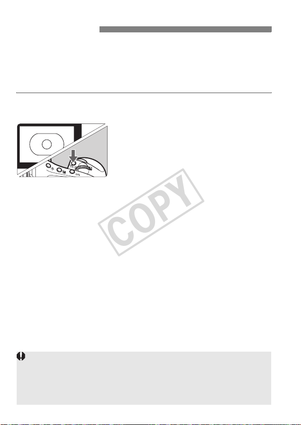
7: FE Lock
COPY
FE (flash exposure) lock locks the correct flash exposure setting for any
part of the scene.
With <a> displayed on the LCD panel, you press the camera’s
<7> button. If the camera does not have the <7> button, press the
<P> button.
Focus the subject.
1
Press the <7> button. (3)
2
Aim the subject at the center of the
viewfinder and press the <7>
button.
X The Speedlite will fire a preflash and
the required flash output for the
subject is retained in memory.
X “FEL” will be displayed in the
viewfinder for 0.5 sec.
Each time you press the <7>
button, a preflash will be fired and a
new flash exposure setting will be
locked.
If the subject is too far away and underexposure will result, the <Q> icon
will blink in the viewfinder. Move closer to the subject and try the FE lock
again.
If <a> is not displayed on the LCD panel, FE lock cannot be set.
If the subject is too small, FE lock might not be very effective.
16

c High-speed Sync
COPY
With high-speed sync (FP flash), the flash can synchronize with all
shutter speeds. This is convenient when you want to use aperture
priority for fill-flash portraits.
Select <c>.
Press the <E> button so that
<c> is displayed.
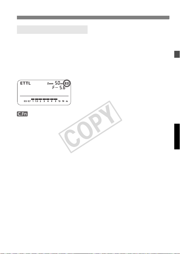
In the viewfinder, check that the <F>
icon is displayed.
If you set a shutter speed that is the same or slower than the camera’s
maximum flash sync speed, <F> will not be displayed in the viewfinder.
With high-speed sync, the faster the shutter speed, the shorter the
effective flash range will become. Check the LCD panel for the effective
flash range.
To return to normal flash, press the <E> button again. The <c>
icon will disappear.
Stroboscopic flash cannot be set.
17
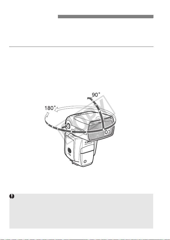
Bounce Flash
COPY
By pointing the flash head toward a wall or ceiling, the flash will bounce
off the surface before illuminating the subject. This can soften shadows
behind the subject for a more natural-looking shot. This is called bounce
flash.
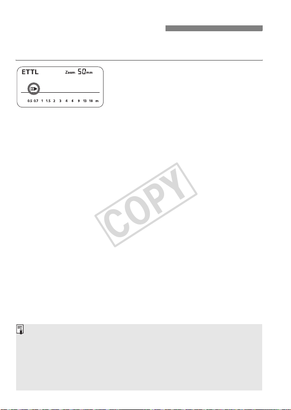
Set the Bounce Direction
Hold down the <z> button and turn the flash head.
If the flash coverage is set automatically, the flash coverage will be fixed
to 50mm.
The LCD panel will also display <O> mm.
You can also set the flash coverage manually.
If the wall or ceiling is too far away, the bounced flash might be too weak
and result in underexposure.
The wall or ceiling should be a plain, white color for high reflectance. If
the bounce surface is not white, a color cast may result in the picture.
After you take the shot, if the flash exposure confirmation lamp does not
light, use a larger aperture opening and try again.
18

Creating a Catchlight
COPY
With the catchlight panel, you can create a catchlight in the subject’s
eyes to add life to the facial expression.
Point the flash head upward by
1
90°.
Pull out the wide panel.
2
X The catchlight panel will come out at
the same time.
Push the wide panel back in.
3
Push in only the wide panel.
Follow the same procedure as for
bounce flash.
Point the flash head straight ahead and then upward by 90°. The
catchlight will not work if you swing the flash head left or right.
For maximum catchlight effect, stay within 1.5 m/4.9 ft of the subject.
Closeup Flash Shooting
When shooting a subject within about 0.5 - 2 m (1.6 - 6.6 ft) away, hold
down the <z> button and tilt the flash head downward by 7° to
illuminate the lower part of the image.
19
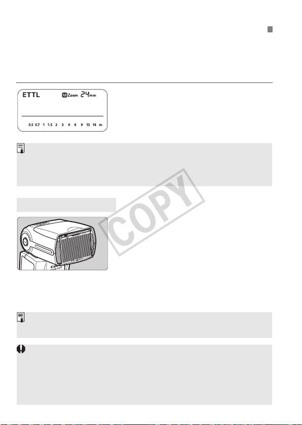
H
COPY
The flash coverage can be set to match the lens focal length from
24mm to 105mm. The flash coverage can be set automatically or
manually. Also, with the built-in wide panel, the flash coverage can be
expanded for 14mm wide-angle lenses.
: Setting the Flash Coverage and Using the Wide Panel
Press the <G> button.
Turn the <9> dial to change the
flash coverage.
If <d> is not displayed, the flash
coverage will be set automatically.
If you set the flash coverage manually, make sure it covers the lens focal
length so that the picture will not have a dark periphery.
If you use a commercially-available sync cord to connect the camera to
the Speedlite’s PC terminal, set the flash zoom manually.
Using the Wide Panel
Pull out the wide panel and place it over
the flash head as shown. The flash
coverage will then be extended for
14mm.
The catchlight panel will come out at
the same time. Push the catchlight
panel back in.
The <G> button will not
work.
The flash coverage will not be compatible with the EF15mm f/2.8 Fisheye
lens.
If you use bounce flash with the wide panel in place, the entire display on
the LCD panel will blink as a warning. Since the subject will be
illuminated by both the bounce flash and direct flash, it will look
unnatural.
Pull out the wide panel gently. Using excessive force may detach the
wide panel.
20
Auto Zoom for Image Size
COPY
EOS DIGITAL cameras have one of three image sizes. The lens’
effective focal length will differ depending on the camera’s image size.
The Speedlite automatically recognizes the EOS DIGITAL camera’s
image size and automatically sets the flash coverage for lens focal
lengths from 24mm to 105mm.
When the Speedlite is attached to a compatible camera, <s> will
appear on the Speedlite’s LCD panel.
Auto zoom can be disabled. (C.Fn-09 → p.27)
21

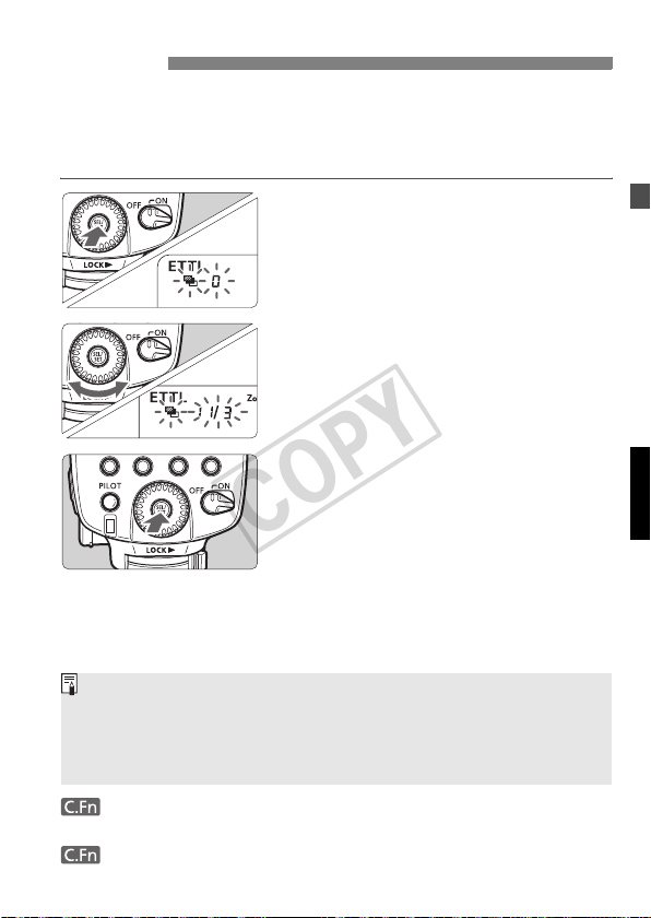
q: Manual Flash
COPY
You can set the flash output from 1/128 power to 1/1 full power in 1/3stop increments.
Use a hand-held flash meter to determine the required flash output to
obtain a correct flash exposure.
Press the <D> button so
1
that <q> is displayed.
Set the flash output.
2
Press the <8> button.
X The flash output blinks.
Turn the <9> dial to set the flash
output, then press the <8> button.
Press the shutter button halfway to
see the effective flash range
displayed.
Flash Output Display
When you change the flash output during shooting, the table below
makes it easier to see how the stop changes such as 1/2 -0.3 → 1/2 →
1/2 +0.3. You can see how the stop changes when you increase or
decrease the flash output.
For example, when you decrease the flash output to 1/2, 1/2 -0.3, or 1/2
-0.7, and then increase the flash output to more than 1/2, 1/2 +0.3, 1/2
+0.7, and 1/1 will be displayed.
(Example) Figures for decreased flash output →
22
1/1 -0.3 1/1 -0.7
1/1
1/2 +0.7 1/2 +0.3 1/4 +0.7 1/4 +0.3 •••
← Figures for increased flash output
1/2 -0.3 1/2 -0.7
1/2
1/4
•••

Metered Manual Flash Exposures
COPY
When the Speedlite is attached to an EOS-1D series camera, you can
set the flash level manually for closeup subjects.
1 Set the camera and Speedlite.
Set the camera’s shooting mode to <q> or <W>.
Set the Speedlite to manual flash.
2 Focus the subject.
Focus manually.
3 Set up an 18% gray card.
Place the gray card at the subject’s position.
In the viewfinder, the entire spot metering circle at the center
should cover the gray card.
4 Press the <7> button. (3)
X The Speedlite will fire a preflash and the required flash output for
the subject is retained in memory.
X On the right side of the viewfinder, the exposure level indicator
will show the flash exposure level for the correct flash exposure.
5 Set the flash exposure level.
Adjust the Speedlite’s manual flash level and the
camera aperture so that the flash exposure level
aligns with the standard exposure index.
6 Take the picture.
Remove the gray card and take the picture.
This feature works only with EX-series Speedlites with manual flash coupled
with an EOS-1D series camera.
23

p: Stroboscopic Flash
COPY
With stroboscopic flash, a rapid series of flashes is fired. It can be used
to capture multiple images of a moving subject in a single photograph.
You can set the firing frequency (number of flashes per sec. expressed
as Hz), the number of flashes, and the flash output.
Press the <D> button so
1
that <p> is displayed.
Select the item to be set.
2
Press the <8> button to select the
item (blinks).
Set the desired number.
3
Turn t he <9> dial to set the number,
then press the <8> button.
X The next item to be set will blink.
After you set the flash output and
press the <8> button, all the
settings will be displayed.
Calculating the Shutter Speed
During stroboscopic flash, the shutter remains open until the firing
stops. Use the formula below to calculate the shutter speed and set it
with the camera.
Number of flashes ÷ Firing frequency = Shutter speed
For example, if the number of flashes is 10 and the firing frequency is
5 Hz, the shutter speed should be at least 2 sec.
24
To avoid overheating and deteriorating the flash head, do not use stroboscopic
COPY
flash more than 10 times in succession. After 10 times, allow the Speedlite to
rest for at least 15 min. If you try to use the stroboscopic flash more than 10
times in succession, the firing might stop automatically to protect the flash
head. If this happens, allow the Speedlite to rest for at least 15 min.
Stroboscopic flash is most effective with a highly reflective subject
against a dark background.
Using a tripod, a remote switch, and external power source is recommended.
A flash output of 1/1 or 1/2 cannot be set for stroboscopic flash.
Stroboscopic flash can be used with “buLb.”
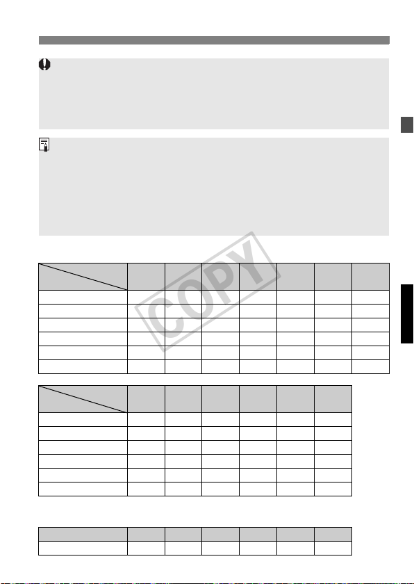
If the number of flashes is displayed as - -, the firing will continue until the shutter closes or
the battery is exhausted. The number of flashes will be limited as shown by the table below.
Maximum Stroboscopic Flashes
Hz
Flash Output
1/4 7 6 5 4 4 3 3
1/8 14 14 12 10 8 6 5
1/16 30 30 30 20 20 20 10
1/32 60 60 60 50 50 40 30
1/64 90 90 90 80 80 70 60
1/128 100 100 100 100 100 90 80
Flash Output
1/4 2 2 2 2 2 2
1/8 4 4 4 4 4 4
1/16 8 8 8 8 8 8
1/32 20 20 20 18 16 12
1/64 50 40 40 35 30 20
1/128 70 70 60 50 40 40
If the number of flashes is displayed as - -, the maximum number of flashes will
be as shown by the table below regardless of the firing frequency.
Flash Output 1/4 1/8 1/16 1/32 1/64 1/128
Flash Count 2 4 8 12 20 40
1 2 3 4 5 6 - 7 8 - 9
Hz
10 11 12 - 14 15 - 19 20 - 50
60 - 199
25
r Second-Curtain Sync
COPY
With a slow shutter speed, you can create a light trail following the
subject. The flash fires right before the shutter closes.
Press the <E> button so that
<r> is displayed.
Second-curtain sync works well in the camera’s “buLb” mode.
To return to normal flash, press the <E> button again. The <r>
icon will disappear.
With E-TTL II/E-TTL, two flashes will be fired even at slow shutter
speeds. The first flash is only the preflash, and not a malfunction.
Stroboscopic flash cannot be set.
Wireless flash cannot be set.
26

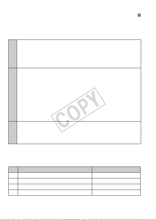
C: Setting Custom Functions
COPY
You can customize Speedlite features to suit your shooting preferences.
You do this with Custom Functions.
Custom
Function
No.
C.Fn-00 Distance indicator display
C.Fn-01 Auto power off
C.Fn-02 Modeling flash
C.Fn-03 FEB auto cancel
C.Fn-04 FEB sequence
C.Fn-05 Flash metering mode
C.Fn-06
C.Fn-07 Test firing with autoflash
C.Fn-08 AF-assist beam firing
C.Fn-09 Auto zoom for sensor size
C.Fn-10 Slave auto power off timer
C.Fn-11 Slave auto power off cancel
C.Fn-12
C.Fn-13
Function
Quickflash with continuous
shot
Flash recycle with external
power source
Flash exposure metering
setting
Setting
Settings & Description
No.
0 Meters (m) -
1 Feet (ft) -
0 Enabled
1 Disabled
Enabled (Depth-of-field preview
0
button)
1 Enabled (Test firing button)
2 Enabled (with both buttons)
3 Disabled
0 Enabled
1 Disabled
0 0 → − → +
1 − → 0 → +
0 E-TTL II/E-TTL p.12
1 TTL p.55
2 External metering : Auto p.30
3 External metering : Manual p.30
0 Disabled
1 Enabled
01/32 -
1 Full output -
0 Enabled
1 Disabled
0 Enabled
1 Disabled
0 60 minutes
1 10 minutes
0 Within 8 hours
1 Within 1 hour
0 Flash and external power
1 External power source
0 Speedlite button and dial
1 Speedlite dial only
Reference
page
p.10
p.44
p.15
p.10
p.49
p.21
p.39
p.48
p.14
27
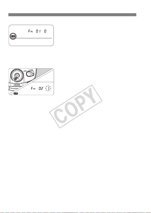
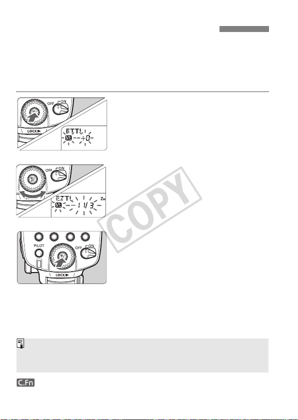
Hold down the <A> button
COPY
1
until <u> is displayed.
Select the Custom Function No.
2
Turn the <9> dial to set the Custom
Function No.
Change the setting.
3
Press the <8> button.
X The Custom Function No. blinks.
X Turn the <9> dial to set the desired
number, then press the <
X After you set the Custom Function
and press the <
camera will be ready to shoot.
D> button, the
8> button.
28

C.Fn-02-3: Convenient when you want to check the depth of field. (p.44)
COPY
C.Fn-12: If an external power source is used, the flash recycling is
powered concurrently by the internal batteries and external
power source. In this case, when the internal batteries
become exhausted first, shooting might not be possible. If 1
is set, the flash recycling will be powered only by the
external power source. The internal batteries will thereby
last longer. Note that even if you set it to 1, the Speedlite will
still require internal batteries for flash control.
C.Fn-05-1 is geared for EOS-series film cameras.
Do not set it if you have a, EOS DIGITAL camera or the EOS REBEL T2/
300X. If C.Fn-05-1 is set for such cameras, the flash control will not work
properly. The flash might not fire or it might fire only at full output.
With Type-A cameras, if C.Fn-05-1 is set, wireless autoflash shooting will
not be possible.
If “AF-assist beam OFF” is set with the Speedlite or camera, the AF-
assist beam will not be emitted.
With Type-B cameras, even if C.Fn-05-0 is set, E-TTL II/E-TTL autoflash will
not work.
29
 Loading...