

Page 1
INSTRUCTIONS
Page 2
Page 3

INTRODUCTION
The Speedlite 577G is Canon’s
most powerful electronic computer
flash unit with many impressive au
tomatic and professional features.
With Canon SLR cameras, it goes
well beyond the conventional mean
ing of automatic in flash photo
graphy. On a Canon New F-1, A-1,
AE-1 PROGRAM, AE-1, AL-1 or AV-1
camera, it will automatically switch
the shutter speed to the flash sync
speed of 1/60 second. (1/90 sec
ond in the case of the New F-1.)
Even the aperture will be set auto
matically for the New F-1 (Shutter-
Priority Mode), A-1, AE-1 PROGRAM,
and AE-1 as long as the lens is on
“A”. If using one of the New F-I’s or
A-I’s slower shutter speeds is de
sirable, that is possible too. Flash
photography with the 577G is as
easy as turning on its power switch,
selecting one of three apertures by
sliding one switch and waiting for
its pilot lamp to glow. Its many spe
cial features and accessories offer
all of the necessary options for
obtaining beautiful and professional
results. For control of shadows and
better modeling of the subject, the
flashhead tilts upward up to 120°
and swings to the left and right
120° each way. Its unique bracket
design insures quick release of the
flash unit for varying the distance
between the flash and the camera.
And since it has a carefully mated,
separate sensor which remains in
the camera’s hot shoe, correct ex
posure is obtained even when the
flash itself is not aimed directly at
the subject.
The 577G normally covers the angle
of view of lenses having a focal
length of at least 35mm, but with its
Wide Adapter 577G-24, flash photo
graphy can also be done with 24 or
28mm lenses. Even flash photo
graphy with a 20mm lens can be
accomplished by attaching the Wide
Adapter 577G-20, an optional ac
cessory. With special synchro cords
which are available on the market
for connecting other Canon Speedlites, synchronized multiple flash is
another option.
* Since the Canon Speedlite 577G
does not have an internal power
source, use of the Canon Tran
sistor Pack G, which accepts
either six C-size batteries or the
Canon rechargeable Ni-Cd Pack
TP, is required.
Page 4

BAS/CS
Assembly......................................................................p.6
Transistor Pack G
How Automatic Flash Control Works
Setting the ASA Film Speed
Setting the Shutter Speed........................................p. 12
Setting an Aperture on the Flash
Setting the Aperture on the Camera
Pre-Shooting Checks
Shooting.....................................................................p. 20
........................................................
.....................
....................................
............................
.......................
...............................................
p.9
p.11
p. 12
p. 14
p. 15
p. 16
Page 5

Page 6
I ^
Page 7
(E)
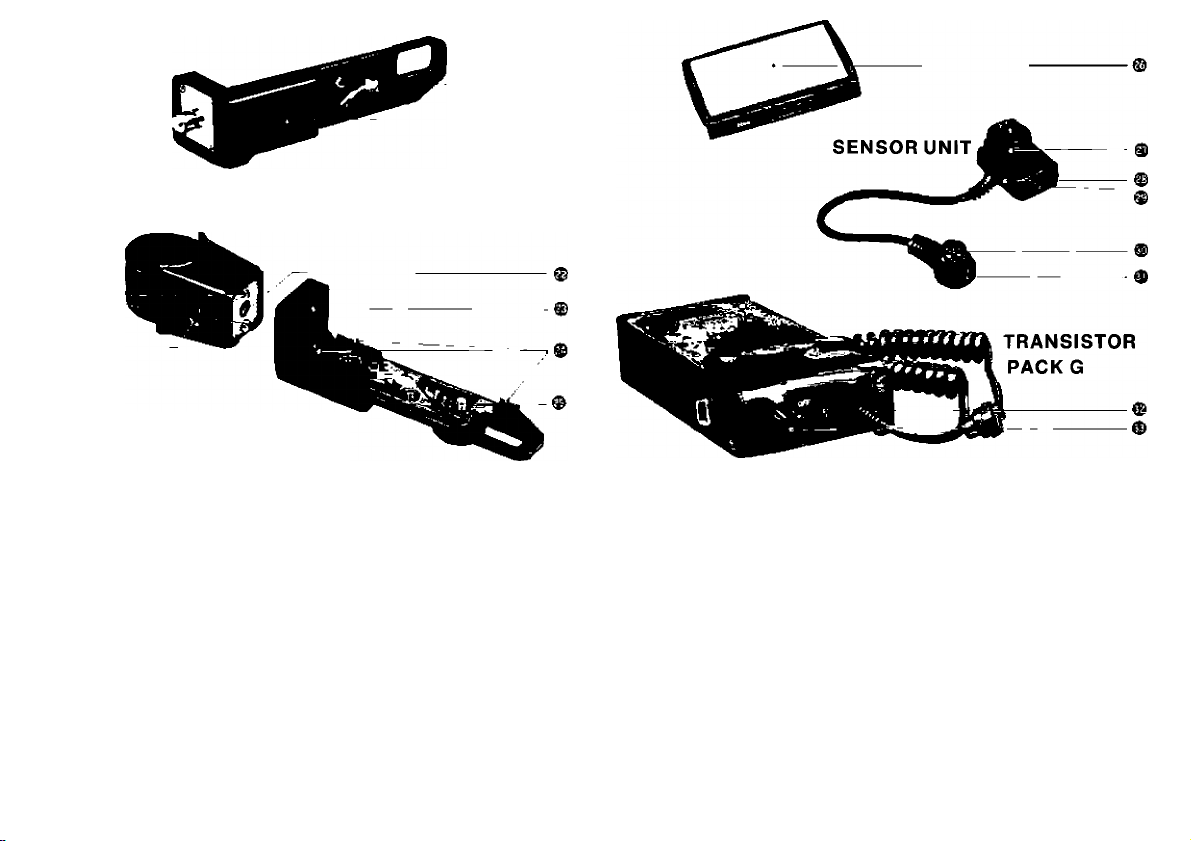
CLAMPING BRACE
iC
CAMERA SUPPORT BRACKET
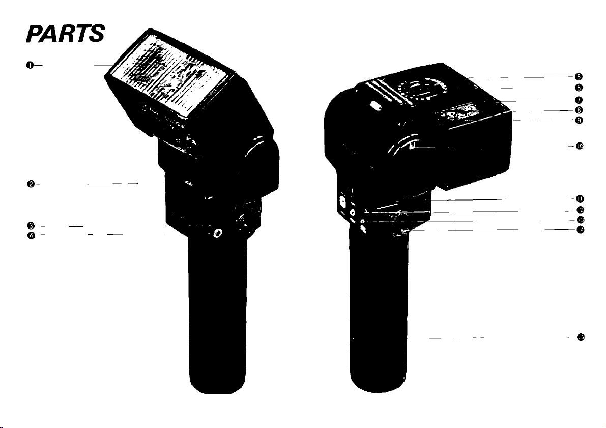
O Flash Head
& Slow-Sync AUTO/MANU Switch ® Pilot Lamp (Flash Test Button)
© AUTO/MANU Switch
@ Transistor Pack G Connecting ® Auto Check Lamp
Socket
O Synchro Cord Socket
© Auto Shooting Distance Range
Scales
© ASA Film Speed Setting Dial
O Attachment Groove for Wide and
Tele Adapters
© Aperture Selection Window
© Aperture Selection Switch
® Tilting Angle Indicator Window
® Sensor Unit Socket
® Positioning Groove
© Bracket Coupling Pin
® Tightening Screws
© Slide Lock Release Button
® Threaded Attachment Point
© Camera Placement Positioning
Groove
© Tripod Screw Socket
® Bracket Coupling Pin Socket
® Motor Drive MF Adapter
Attachment Site
® Framing Guides
® Tripod Socket Screw
® Wide Adapter 577G-24
© Lock Nut
© Synchro Cord A Socket
© Sensor
© Connecting Plug
© Coupling Index
© Pilot Lamp
© Power Switch
Page 8
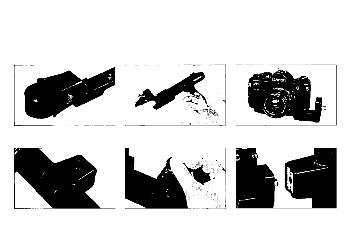
ASSEMBLY
Slide lock button to left. While
holding it in, pull flash section
apart from camera support.
Align the index on the clamp
with positioning groove on the
grip.
Screw large tripod-type screw
into the threaded end of the
groove.
After sliding clamp on grip, re
tighten the two screws on flash
section.
Adjust position of support be
fore completing.
Align flash section
camera support section
push them together.
Page 9

(1) Bracket to Camera
1. Slide the lock button on the flash
section of the bracket to the left
and, while holding the button in,
separate the flash section from the
camera support section (Photo 1).
2. Screw the iarge tripod-type screw
into the camera support section of
the bracket to the screw thread at
one end of the groove (Photo 2).
3. Screw the tripod-type screw part
way into the tripod socket on the
camera’s base. Before screwing it
in the rest of the way, shift the
camera support back and forth
untii the ridges across the front of
it are right up against the front of
the camera. Make sure the
camera is not sitting on top of
these ridges. Also adjust the
support sideways for the best fit.
Then finish tightening the screw
(Photo 3).
(2) Bracket to 577G’s Grip
1. With a coin or a similar object,
loosen the two large screws on the
flash section. Separate the clamp
from the rest of the section.
2. Align the index on the ciamp
with the positioning groove on the
grip and siide the clamp as far up
around the grip as you want (Photo
4).
3. Realign the flash section with the
clamp and retighten the two
screws (Photo 5). The clamp
should be positioned on the grip
so that, when assembly is com-
pieted, the flash will be facing
straight ahead, in the same direc
tion as the lens.
(3) Flash Section to Camera
Support Section
Align the flash and camera support
sections of the bracket and push
them together (Photo 6). The lock
button on the flash section will spring
to the right when the two parts are
iocked together.
* To separate the two sections of
the bracket, siide the lock button
on the flash section to the left and
push it in. The lock button must
also be in this position for cou
pling the two sections as above.
Page 10
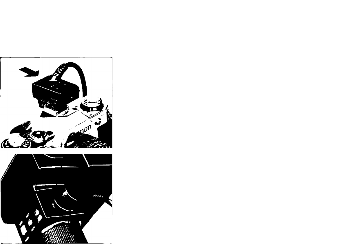
(4) Sensor Unit G20 to Camera
and Flash
Rather than having a built-in sensor,
the 577G has a separate one which
slips into the camera’s accessory
shoe. It is very finely attuned to the
particular Speedlite 577G with which
it comes so that it can give the best
results possible.
1. Loosen the sensor's lock nut and
slide it into the camera’s acces
sory shoe so that its eye is facing
forward. If the accessory shoe is
a hot shoe, be careful to push the
sensor all the way in so that pro
per electrical connection will be
made. Then tighten the lock nut.
2. To connect the sensor with the
577G, align the index on the plug
at the end of its cord with the
index on the 577G’s sensor socket
and push the plug in all the way.
♦ If the camera does not have a hot
shoe, Synchro-Cord A, an op
tional accessory, must also be
attached. See p. 31.
• A flash coupler must be used to
attach the sensor to the Canon
F-1. Three are available as op
tional accessories. Flash Coupler
F is especially for this combina
tion. Flash Coupler D or L may
also be used.
• Since the 577G and the sensor
provided with it are so carefully
matched to each other, they
should be considered a set. Do
not use the 577G with a different
sensor unit G20.
Page 11
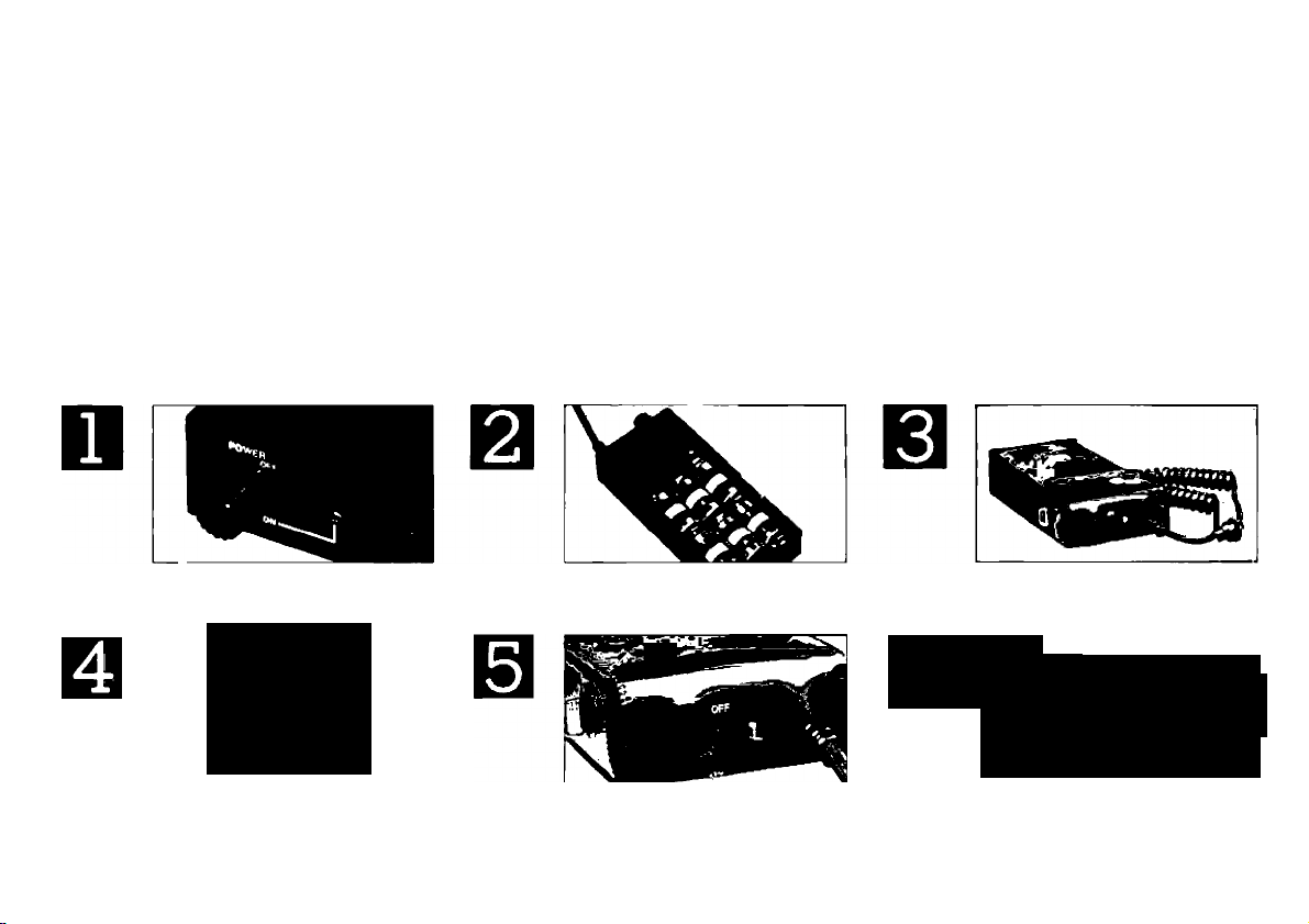
TRANSISTOR PACK G
This accessory provides power for
Speedlite 577G.
Proper Batteries: Six new C-size al
kaline-manganese batteries or the
Canon Ni-Cd Pack TP (optional
Turn off the transistor pack’s
power switch.
-V
y
Align the plug’s index with
the 577G’s power source
socket index. Push plug into
socket.
accessory), which is rechargeable.
The Ni-Cd pack should be fully
charged.
Insert the set of six alkalinemanganese batteries into
battery magazine TP.
Turn on transistor pack’s
power switch. Lamp next to it
should light up.
Insert the transistor pack into
its case and rehook the cord.
611
L
Turn 577G’s AUTO/MANU
switch to AUTO for auto
matic flash control.
M/TO
A
^ UANU.
TEST
■1
PILOT
m
CHECK 1
j
1
AUTO 1
Page 12

1. Unhook the Transistor Pack G’s
cord from its case and remove the
pack from the case.
2. Turn off the transistor pack’s
power switch (Photo 1).
3. Insert the set of six al
kaline-manganese batteries into
battery magazine TP as illustrat
ed. Then align the contact on the
magazine with the transistor
pack’s and insert the one into the
other (Photo 2).
OR
Insert a fully-charged Ni-Cd Pack
TP into Transistor Pack G the
same way as battery magazine TP
is inserted.
4. Reinsert the transistor pack into
its case as shown in the photo.
Then rehook the cord (Photo 3).
5. Align the index on the plug at the
end of the transistor pack’s cord
with the index on the 577G’s ex
ternal power source socket. Push
the plug securely into the socket
10
(Photo 4).
6. Turn on the transistor pack’s
power switch. The lamp next to
the power switch should light up
(Photo 5).
7. Make sure the usual preparations
as described in the following
pages have been made on
camera, flash and lens and wait
for the 577G’s pilot lamp to glow.
Then take the picture (Photo 6).
* The transistor pack’s operation
lamp glows as long as the power
switch is on and there is power.
However, even when it is glowing,
the batteries should be replaced
with new ones or the Ni-Cd Pack
TP should be recharged if the
flash unit’s recycling time be
comes longer than usual.
* When the batteries wear out, re
place all of them at the same time
with a set of new ones which are
all of the same brand.
* If you do not expect to use Tran
sistor Pack G for a long time, re
move the alkaline-manganese
batteries from the magazine. NiCd Pack TP may be left inserted
but the power switch must be off
to prevent corrosive battery
ieakage and other potential dam
age.
* Be sure the transistor pack’s
power switch is off whenever it is
not in use.
* Should the battery temperature
rise in continuous shooting with Csize batteries, you may rest at
ease, for it is a normal condition.
* There is a protective lining be
tween Battery Magazine TP and
Transistor Pack G.
Before using, remove this lining.
It may be thrown away.
Page 13

HOW AUTOMATIC FLASH
CONTROL WORKS
The 577G’s sensor acts something
like the camera’s photocell; it
measures the intensity of light from
the flash which is reflected back from
the subject. When it decides that the
subject has received enough light, it
automatically cuts off flash emission.
Flash Mode
Full Autoflash
Automatic
Shutter Setting
Autoflash
Normal
Autoflash
A-1.AE-1 PROGRAM,
AE-1, New F-1 (ShutterPriority AE Mode)
AL-1, AV-1, New F-1
(Aperture-Priority AE
or Manual Mode)
F-1 or other
cameras
Camera
In order to do this properly, the
sensor must, like a camera’s photo
cell, be as close to the film as possi
ble and facing the subject. Since the
577G’s sensor is separate in the
camera’s accessory shoe, it is always
in the best position to measure the
light correctly even while the flash
unit itself can be aimed in many dif
ferent directions for the best lighting
effect.
Shutter Speed
Setting
Automatically switches
to X-sync unless on
"B"
Automatically switches
to X-sync unless on
"B"
Manual
(to X-sync)
Aperture Setting
Automatic (When
using FD lens set on
“A" mark)
Manual
Manual
To make its decision on when the
subject has received enough light,
the sensor must know three things:
1) the film speed, 2) the aperture and
3) the shutter speed. You must
always set the ASA film speed on the
flash by hand, but depending on the
camera you use, the flash may set
the aperture, the shutter speed or
both automatically. The table on the
left shows the various ways that the
aperture and shutter speed may be
set with various cameras.
11
Page 14
SETTING THE
SETTING THE
ASA FILM
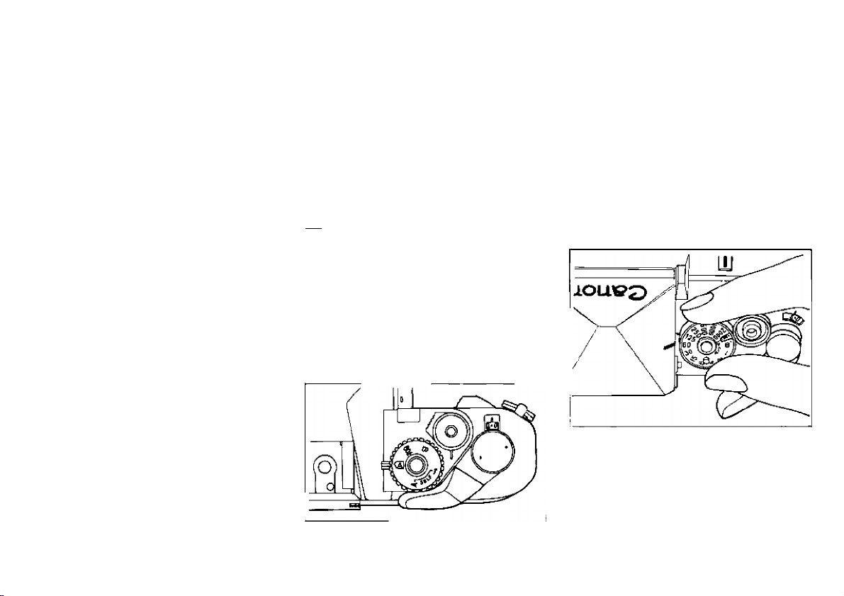
The sensor must know the ASA film
speed to give correct exposure.
Make sure it is set correctly on both
the camera and the flash. To set it on
the 577G, rotate the calculator dial
until the film speed index is aligned
with the ASA speed which corres
ponds to that of the film in the
camera.
SHUTTER SPEED
Canon New F-1
Normal Flash Photography; Once
the 577G is attached to the
camera and its pilot lamp is glow
ing, the camera switches auto
matically to a sync speed of 1/90
sec., provided the shutter dial is
not on “B”.
Slow Sync Flash: Set the 577G’s
slow sync switch to MANU. Then
turn the camera’s shutter dial to
any speed from 1/60 sec. to 8
sec.
Canon A-1 Camera
Normal Flash Photography: Make
sure the 577G's slow-sync
AUTO/MANU switch is on
“AUTO”. Except for “B” (Bulb), the
AT dial and AE mode selector may
be on any setting and the shutter
speed will switch to 1/60 sec., the
flash synchronization speed,
automatically as soon as the
577G’s pilot lamp glows. If the AT
dial is set to “B”, you will be in
control of exposure duration just
as you normally are with “B”.
AUTO ProHirn MANU. 1/60-30S
J
12
Page 15
Slow Sync Flash: Set the 577G’s
slow-sync AUTO/MANU switch
on "MANU”. Set the AT dial to a
shutter speed from 1 /60 sec. to 30
sec. The picture will be taken at
the speed to which the dial is set.
Canon AE-1 PROGRAM, AE-1, and AL-1
Except for "B”, the shutter speed dial
may be on any setting and the shut
ter speed switch to the flash sync
speed of 1/60 sec. automatically as
soon as the 577G’s pilot lamp glows.
If the dial is set to “B”, “B” will be the
exposure duration.
Canon AV-1
The shutter speed will switch to the
flash sync speed of 1/60 sec. auto
matically when the 577G’s pilot lamp
glows if the selector dial is on the red
(a] (the preferable setting). It will
stay on 1/60 sec. continuously if the
dial is set to “60^ ”. If the dial Is on
"A Self" or “Self^”, the shutter
speed will be 1/60 sec. and the
flash will be synchronized with the
camera for a delayed shot by selftimer.
Other Cameras
Set the shutter speed dial by hand to
the camera’s X flash synchronization
speed: e.g., to 1/60 sec. or slower on
the Canon F-1.
13
Page 16

SETTING AN APERTURE
ON THE FLASH
You set an aperture with the aperture
selection switch on the back of the
577G. The switch has three colorcoded positions: red, green and yel
low. As you slide the switch, the color
of the position you have set will
appear in one of three windows on
the back of the flash.
a) Auto Shooting Distance Ranges
b) Auto Aperture Indices
c) Selection Switch Position
Indicators
14
Each position has a corresponding
aperture and auto shooting distance
range. The auto aperture is the fnumber which is directly opposite
the dot which is the same color as
the position of the aperture selection
switch. It changes with the ASA film
speed you have set on the calculator
dial. For instance, if you have set the
aperture selection switch to the red
position, the auto aperture will be
f/2.8 at ASA 100 but f/5.6 at ASA 400.
The auto shooting distance range is
indicated by the straight white line
which is directly opposite the set
ting of the aperture selection switch.
There are three lines, one for each
position of the switch. Each repre
sents the range of distances from the
subject for which that position of the
selection switch will give correct ex
posure. If the camera is out of that
range, the subject will be over- or
underexposed. There are two ways
to check that the camera is within
that range: either by reading the
lens’ distance scale after focusing
or by the auto check lamp (see p. 16).
When you are deciding which of the
three positions of the selection
switch you should set, place prime
importance on the shooting distance
range. If the actual shooting distance
falls within the range of two or all
three positions, take depth of field
into account.
* The indicated auto shooting dis
tance ranges only hold true if the
flash is pointing straight at the
subject. If the flash head is tilted
or swung for bounce flash, or if
the flash is held some distance
from the camera, rely on the auto
check lamp to tell you if you are
within the correct range (see p.
26). These ranges also change if
a wide or tele adapter is at
tached. See p. 23 and “Specifi
cations”, p. 35.
Page 17

SETTING THE APERTURE
ON THE CAMERA
New F-1 (Shutter-Priority Mode),
A-1, AE-1 PROGRAM, and AE-1
•FD Lens: Leave the lens on “A”.
The aperture you have set on the
flash will be set on the camera
automatically when the 577G’s
pilot lamp glows. The settings of
the A-Ts AE mode selector and
AT dial do not matter (except in
relation to shutter speed, p. 12). [If
you wish, you may remove the
aperture ring from “A” and turn it
to the auto aperture you have set
on the flash or to a different
aperture to make an exposure cor
rection. In this case, remember to
reset the aperture each time you
reset the selection switch on the
577G.]
• FL Lens: See “Other Cameras”,
next column.
New F-1 (Manual, Aperture-Priority
Modes) and Other Cameras
Turn the aperture ring to the same
aperture you have set with the selec
tion switch on the flash or to a dif
ferent aperture if you wish to correct
exposure.
15
Page 18

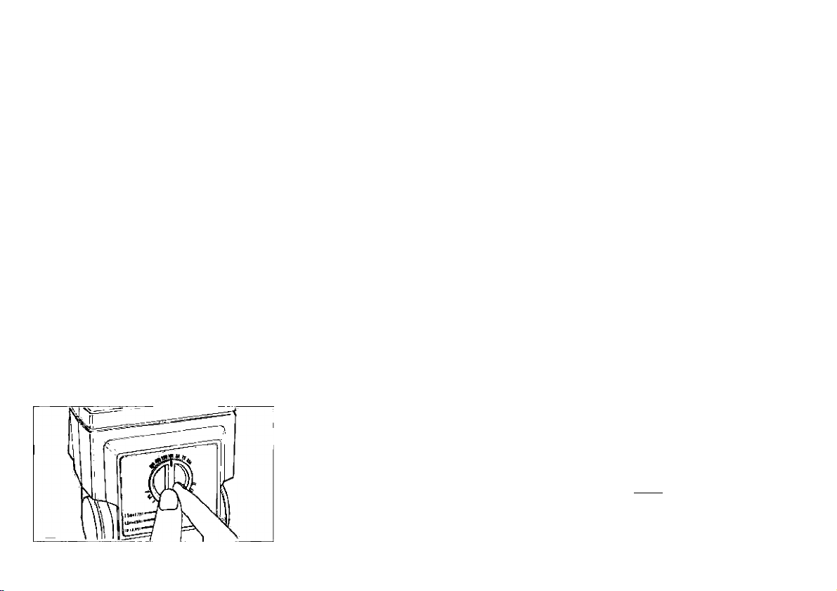
PRE-SHOOTING CHECKS
I. Test Firing and Auto Shooting
Check
b) Pilot lamp
c) Auto Check Lamp
Now that all camera, lens and
flash settings have been made,
turn on the power switch on
Transistor Pack G. After the flash
reaches sufficient charge for firing,
the pilot lamp will glow and you
can take a flash picture anytime.
If you wish to check the flash and
whether the shooting distance is
correct, press the pilot lamp after
it glows. A flash should be fired. If
the auto check lamp next to the
pilot lamp lights up right after
wards for about two seconds, it
means that your shooting distance
will give correct exposure. If it
does not glow, either set the aper
ture selection switch to a better
position or move closer to your
subject. This method of checking
shooting distance is especially
helpful when the flash is tilted or
swung for bounce flash (p. 25).
• The auto check lamp tells you
whether you are close enough to
your subject but not whether you
are far enough away. Even if you
are too close to get a wellexposed picture, it will still glow,
so always keep the shooting
ranges given on the back of the
flash in mind and double check
the lens’ distance scale if you think
you might be too close.
II. Checking Viewfinder Infor
mation
The Canon New F-1, A-1, AE-1
PROGRAM, AL-1, AE-1 and AV-1
have special viewfinder informa
tion for flash photography. You
can check it by pressing the
shutter button halfway after the
pilot lamp glows.
New F-1 Information
(1) Full Autoflash Mode; Shutter-
Priority AE Mode (with AE Motor
Drive FN or AE Power Winder
FN attached, FD lens on “A”
and shutter dial not on “B”).
(example)
I,
Ì*
1
Ù
30
16
Page 19

Film Speed of ASA 100; Aper
ture Selection Switch at red
position; Slow-Sync AUTO/
MANU Switch on AUTO.
* Shutter speed is automatical
ly set to 1/90 sec., even
though shutter speed display
shows what has been set on
the shutter dial.
(2) Automatic Shutter Setting Auto
flash Mode: Manual Mode or
Aperture-Priority AE Mode (the
latter mode with AE Finder FN,
shutter dial on “A").
(example)
30
Manual Mode: Turn the lens ap
erture ring to the same aperture
set on the flash. The aperture
needle points to the aperture
that has been set on the lens.
Aperture-Priority AE Mode: Film
Speed of ASA 100; Aperture
Selection Switch at red position;
Slow-Sync AUTO/MANU Switch
on AUTO.
II4 8 I ; > I B » io1b5 ao m m» ~|
Manually set the aperture to
the lens the same aperture
that has been selected for the
flash.
The camera switches auto
matically to X-sync (1/90
sec.) and the meter needle
points to the right of 1/60
sec.
P
A-1 Information
(1) Full Autoflash Mode: FD lens on
“A” and AT dial not on “B”.
(example)
ED F E . B
Film Speed: ASA 100, Aperture
Selection Switch: Red position,
Slow-sync AUTO/MANU Switch:
on AUTO.
(2) Automatic Shutter Setting Auto
flash Mode: FD lens off “A” and
AT dial not on “B”.
(example)
F 3.5
Film Speed: ASA 64, Aperture
Selection Switch: Yellow posi
tion, Slow-sync AUTO/MANU
Switch: on AUTO.
17
Page 20

60
..........
indicates shutter speed is
1/60 second.
F............indicates sufficient charge
for firing flash.
2.8, 9.5...is the aperture set on flash.
Even if you turn the aper
ture ring to a different
aperture from that set on
the fiash, the viewfinder wili
still show the aperture on
the flash. However, the pic
ture willl be taken at the
aperture you have set on
the lens.
M
...........
reminds you that you have
taken the aperture ring off
"A” to set an aperture by
hand.
* With an FL lens, viewfinder infor
mation on aperture is not aiways
reliable. Make sure the aperture
ring is set to the aperture chosen
on the flash.
• If the AT dial is on “B”, “bu” re
places shutter speed information
18
in the viewfinder for both fiash
modes. Automatic fiash control is
possible on “B”.
(example)
E . B
* The aperture display may be one
half f/stop off the one set on the
flash. This is because the aperture
display is rounded off to half
f/stops; it wiil not affect exposure.
A-1 Warnings
1. Aperture display blinks showing
maximum aperture: means the
aperture set on the flash is probabiy iarger than the lens’
maximum aperture. Set the aper
ture selection switch to a smalier
aperture. Be sure to check the
aperture set on the flash if this
happens.
(if the display blinks with an aper
ture which is the same as the lens’
maximum aperture, exposure will
be correct anyway.)
2. Aperture display blinks showing
aperture of 1/16 to f/32: means
aperture set on fiash may be too
smail. Check the aperture set on
the fiash. If it is the same or larger
than the lens’ minimum aperture,
exposure wiii be correct. Other
wise, set the 577G’s aperture se
lection switch to a larger aperture.
Page 21

AE-1 PROGRAM, AE-1 Informa
tion
(1) Full Autoflash Mode; FD lens on
“A” and shutter speed dial not
on “B”.
(example)
Film Speed: ASA 100; Aperture
Selection Switch; Red position.
(2) Automatic Shutter Setting Auto
flash Mode: FD lens off “A” or
FL lens. (“M” mark will flash in
AE-1 viewfinder, and will light
up in AE-1 PROGRAM view
finder. It reminds you that you
have taken the aperture ring off
“A” for manual aperture setting.)
AE-1 PROGRAM Warnings
The aperture selected on the flash
will blink in the viewfinder if that ap
erture is larger than the maximum
aperture of the lens.
AE-1 Warnings
1. Underexposure warning lamp
blinks: means the aperture set on
the flash is larger than the lens’
maximum aperture. Set the aper
ture selection switch to a smaller
aperture (lamp should stop blink
ing).
2. Meter needle swings into
overexposure warning zone:
means aperture set on flash may
be too small. Check it. If it is the
same or larger than the lens’
minimum aperture, exposure will
be correct. If it is smaller, set the
aperture selection switch to a
larger aperture.
AL-1,AV-1 Information
(1) Automatic Shutter Setting Auto
flash Mode: Selector dial not on
“B”.
* Synchronized flash photography
is possible only when the meter
needle points to 1/60 second.
19
Page 22

SHOOTING
Once all preparations detailed on the
preceding pages have been made,
make sure the subject is in focus and
that the 577G’s pilot lamp is glowing.
Then press the shutter button to take
the picture. If the auto check lamp
glows immediately afterwards, it
means that you were close enough to
the subject for correct exposure.
* In delayed flash photography with
the camera’s self-timer, do not
press the shutter button to set the
timer until the pilot lamp glows.
* When the shooting distance is less
than one meter, the difference be
tween the optical axes of the lens
and the flash may result in uneven
lighting.
* Since it is possible for viewfinder
information in the New F-1, AE-1,
AL-1, or AV-1 to be the same in
flash photography as in normal
AE photography, it is advisable to
check that the pilot lamp is glow
ing before shooting.
20
♦ You can continue flash photo
graphy if the pilot lamp is still
glowing after the shutter is re
leased. If the pilot lamp does go
out after a flash shot, you can
take a shot in the normal AE
mode while waiting for it to glow
again. (This, however, does not
apply when the shutter speed is
set to “B” or when the camera is
not set for AE photography.)
Make sure that the shutter speed
or aperture which will be used for
normal AE photography will give
correct exposure, too.
♦ When the flash is no longer
necessary, be sure to turn off
the Transistor Pack G’s power
switch to prevent battery drain.
With the power switch off, it is
possible to shoot normally without
detaching the flash or the sensor.
♦ While performing normal AE
photography as the flash recycles,
there is a possibility that, while the
shutter curtain is open, the 577G’s
pilot lamp will glow and the flash
may fire. In this case, correct ex
posure cannot be guaranteed.
PROBLEM BACKGROUNDS
Certain types of background may
lead to incorrect exposure. A very
small subject against a very dark or
distant background may turn out
overexposed. On the other hand, if
the surroundings are bright white
with strong reflections, the subject
may be underexposed.
J
Page 23

Page 24

SPECIAL FEATURES
Wide Adapter 577G-24.....................................................p. 23
Manual Flash Photography...............................................p. 24
Bounce Flash...,
Bounce Flash on Manual..................................................p. 26
Slow-Sync Flash Photography
(with Canon New F-1 and A-1 only)
Multiple Flash....................................................................p. 30
Use of 577G on Camera without Hot Shoe......................p. 31
22
J,
............
..............................................p. 25
.........................................
p. 28
Page 25

Page 26

WIDE ADAPTER 577G-24
Normally, light from the 577G is
spread wide enough to cover the
angle of view of a 35mm or longer
lens. If it were used with a wider
angle lens, the edges of the picture
would be too dark. With the Wide
Adapter 577G-24, the flash unit’s
light is diffused enough to cover the
angle of view of 24mm and 28mm
lenses also. (It may also be used with
lenses longer than 28mm). At the
same time, the unit’s power is re
duced and the farthest distances at
which you can shoot are closer than
they usually are.
To attach the wide adapter, simply
slide it in the grooves of the flash
head so that the colored distance
scales on its one side are facing the
back of the flash. These distance
scales, which show the reduced
shooting ranges, replace the ones
below the calculator dial. They are
color-coded to match the three po
sitions of the aperture selection dial.
In all other respects, the flash may be
used as usual.
* With Wide Adapter 577G-24
attached, the 577G’s guide
number becomes 28 at ASA100.
* If you use the flash with Wide Ada
pter 577G-24 and a 24mm lens to
copy a flat subject, the picture
will be dark around the edges.
This combination is mainly for
taking pictures of three-dimen
sional subjects.
* For using the flash with a lens
having a focal length down to
20mm, Wide Adapter 577G-20 is
available as an optional accessory.
23
Page 27

MANUAL FLASH PHOTOGRAPHY
Setting the flash mode switch on the
back of the 577G to MANU puts the
unit on manual operation. While on
automatic the 577G’s sensor auto
matically cuts off the flash duration
at the correct point, on manual the
flash operates at maximum dura
tion for every firing. The shutter
speed should be set as usual (p. 12),
but the correct aperture can no
longer be found with the unit’s cal
culator dial. Instead, it must be cal
culated using a guide number for
mula, which follows:
f/stop =
24
Guide Number
Shooting distance
Since the guide number changes
with film speed, the 577G is provided
with a sticker which gives the guide
numbers in meters for various ASA
film speeds. Guide numbers are also
given for when a Tele Adapter 577G
or Wide Adapter 577G-24 or 577G20 is attached. The sticker should be
attached to a convenient place on
the flash unit, such as on the under
side of theflashhead.
Since these guide numbers are ex
pressed in meters, the shooting dis
tance in the guide number formula
should also be in meters. When the
flash is used normally, pointed
straight at the subject and neither
tilted or swung nor held away from
the camera, the shooting distance
may be read directly from the lens’
distance scale after focusing. If the
flash is held away from the camera,
the shooting distance means the dis
tance from flash to subject, which
should be measured with a tape
measure if necessary. (Remember
that for holding the flash away from
the camera a synchro cord is
necessary.)
The 577G’s pilot lamp lights up once
the flash has reached sufficient
charge, which does not mean that it
is fully charged yet. While compen
sation for this is automatic when the
flash is on automatic operation, it is
not when the flash is on manual.
Therefore, it is necessary to wait for
about 15 seconds after the pilot
lamp lights (i.e., until the flash re
aches maximum charge), before you
press the shutter button. If you are
not using new or fully charged bat
teries, it will be necessary to wait
longer. If it is absolutely necessary to
fire the flash immediately after the
pilot lamp glows, open the lens
around one f/stop to make up for the
fact that the flash is not yet fully
charged.
Page 28

BOUNCE FLASH
Using the 577G on manual operation
is recommended whenever you run
into a problem background (p.20),
when you are shooting at very close
range or when you are attempting
special effects, such as a high or lowkey picture, or using the flash as fill
in daylight.
Light from a flash pointed directly at
the subject tends to be harsh and
bright, creating a large difference
between dark and bright areas of the
picture. A softer, less contrasty,
often more pleasing light, which
usually does a more effective job of
modeling the subject, can be created
by bouncing the flash off a nearby
wall or ceiling.
The 577G’s head can be tilted up
wards up to 120° with click-stops at
60°, 75° and 90° for bouncing the
light off the ceiling. It can also be
swung 120° to the left or right with
click-stops at 60°, 75°, 90° and 105°
for bouncing the light off a wall. The
flash head may be both tilted and
swung at the same time, taking into
account the distance from flash to
wall or ceiling and from wall or ceil
ing to subject, for the best overall re
sults. It need not be set to a clickstop position for firing.
Page 29

BOUNCE FLASH
ON MANUAL
When the flash is bounced off a wall
or ceiling before it reaches the sub
ject, it is actually traveling a longer
distance than it would be if it were
aimed directiy at the subject. As a
result, the light intensity is weaker
and it is necessary to take this extra
distance into account to be sure of
correct exposure. As long as the
auto check lamp (p. 16) lights up
after actuai or test firing, there will be
enough light. It is important to re
member that the distance scaies on
the back of the unit do not apply
when the flash is bounced. Other
than that, the flash may be used as
usual.
The surface off which the flash is
bounced shouid preferably be white
or near-white, fairly large and highly
reflective, if the reflecting surface is
colored, the subject may turn out
tinted that coior. The color may also
be disappointing if the surface is a
poor reflector. A very high ceiling
26
does not make a good surface for
bounce flash; a better solution wouid
be to bounce the flash off a whitecard reflector. Generally, the closer
the flash is to the surface, the
brighter and higher in contrast the
picture.
it is generaily said that there is a
loss of light intensity of about two
f/stops when the flash is bounced off
a 2.5 meter high ceiiing. Losses of
this order require an adjustment in
the f/stop calcuiated by guide
number formuia when the flash
mode switch is on MANU. Since the
exact correction depends on the dis
tance of the reflecting surface from
the flash and subject, its color and its
reflectivity, it is best to bracket ex
posure.
Page 30

Direct Flash Photography
Page 31

Bounce Flash Photography
27
Page 32

SLOW-SYNC FLASH PHOTOGRAPHY
(WITH NEW F-1 AND A-1 ONL Y)
In normal use, the best shutter
speed for flash photography with
most Canon SLRs, including the
New F-1 and A-1, is the X-sync
speed (1/90 sec. for New F-1 and
1/60 sec. for A-1). It is just slow
enough for the first shutter curtain
to travel across the film before the
second shutter curtain is released,
which means that the entire film will
be exposed to the flash. On the
other hand, it is just fast enough to
stop the motion of most subjects re
quiring flash.
When you use this flash on a Canon
New F-1 or A-1, however, you have
the option of taking a flash picture
at a shutter speed slower than Xsync. Simply set the 577G’s slowsync AUTO/MANU switch to MANU
and the camera’s shutter speed to a
speed slower than X-sync. Thus, for
the New F-1, set the shutter dial to
any speed between 1 /60 sec. and 8
sec; for the A-1, set the AT dial to
28
any speed between 1/30 sec. and
30 seconds. The picture will be
taken at the speed you have set on
the camera, and the flash will fire
after release of the first shutter cur
tain. The advantage of using a shut
ter speed slower than X-sync is that
the background will look lighter.
But, even with the switch set to
MANU, if the shutter speed that has
been set on the camera is at X-sync
or faster (i.e., 1/90 sec. or faster
with the New F-1, and 1/60 sec. or
faster with the A-1), the actual shut
ter speed will be set automatically
to the X-sync. In all other respects,
use of the flash remains the same.
AUTO I Wl MANU. 1/60-30S
J
The shutter speed display in the
A-1's viewfinder will show the
one set with the AT dial.
With any camera other than the
New F-1 or A-1, it does not mat
ter whether the slow-sync
AUTO/MANU switch is on AUTO.
The shutter speed is set accord
ing to information on p. 12.
EFFECT OF AUTO/MANU POSITIONS AND
A-1 's "AT’ DIAL ON ACTUAL SHUTTER SPEED]
Setting of
Slow-Sync
AUTO/MANU
Switch
AUTO
MANU
AT
Dial Setting
any setting
but “B"
"B"
1/60 sec. 1 /1000 sec.
1 /30 sec. -
30 sec.
"B"
Actual
Shooting
Shutter Speed
1 /60 sec.
“B"
1 /60 sec.
speed set on
AT dial
•■B"
Page 33

Normal Flash Photography
Slow-Synch Flash Photography
29
Page 34

MULTIPLE FLASH
It is possible to synchronize another
Canon Speedlite, such as the 155A,
177A or 199A, with the 577G by con
necting them together with a Yshaped synchro cord. Three or more
of these flashes may be fired
simultaneously by equipping those
which are not on the camera with
slave units. Y-shaped synchro cords
and slave units are optionally avail
able on the market. The following il
lustrations show how to make the
necessary connections.
All of the flash units, including the
577G, should be used on manual. If
the flash has an AUTO/MANU mode
switch, slide it to MANU.
The proper aperture may be found
by guide number formula (p.24)
based on an overall guide number
which can be calculated with the fol
lowing equation:
30
G = \/ Gi^ -F G2^ -|- Ga^ -h ... Gn^
G = effective guide number
Gi, G2, G3... guide number of each
Speedlite
Page 35

USE OF 577G ON CAMERA
WITHOUT HOT SHOE
The aperture found by putting this
guide number into the guide number
formula must then be set on the lens
by hand no matter what the camera.
Please note that the above equation
is only useful when all of the flashes
are placed close to the camera and
pointed straight at the subject.
* If a multi-flash setup is used with
a Canon AL-1 or AV-1 camera,
use a Canon Hot-Shoe Adapter
(optional accessory).
* When using the 577G with the
New F-1, A-1, AE-1 PROGRAM, or
AE-1, set the shutter speed at Xsync or slower. Set the lens aper
ture manually off the “A” mark
using the guide number formula.
If the camera does not have elec
trical contacts for flash photography
in its accessory shoe, a synchro cord
must be connected between the
sensor and the camera for proper
synchronization. Available for this is
an optional accessory called Canon
Synchro Cord A. First make sure the
Transistor Pack G’s power switch is
off. Plug the two-pronged end of the
cord into the socket on the side of
Sensor Unit G20. Plug the other end
into the camera’s PC socket. For
setting the shutter speed and aper
ture, see “Other Cameras”, pp. 13,
15.
Page 36

RELATED OPTIONAL ACCESSORIES
Wide Adapter 577G-20 Sensor Unit G100
32
Tele Adapter 577G
Flash Coupler F
Adapter For Motor Drive MF
Page 37

Wide Adapter 577G-20
This accessory performs the same
function as Wide Adapter 577G-24
except it makes it possible to use the
577G with lenses down to 20mm in
focal length. It should be attached in
the same way as Wide Adapter
577G-24 and also has color-coded
distance ranges on its side which re
place those on the flash. In all other
respects, the flash may be used as
usual. With this accessory, the
577G’s guide number becomes 24 at
ASA 100.
Tele Adapter 577G
This screen is for using the 577G
with a lens having a focal length of
100mm or more. Simply slide it over
the flashhead in the same way as the
Wide Adapter 577G-24 so that the
colored distance ranges on its side
can be seen from the back of the
camera.
Sensor Unit G100
This accessory assures correct ex
posure measurement when the flash
is detached and used up to about
one meter away from the camera. It
may be attached in the same way as
Sensor Unit G20.
Flash Coupler F
This accessory is specially designed
for mounting the 577G’s sensor on a
Canon F-1 camera. Further details
may be found in its individual in
structions.
Adapter for Motor Drive MF
With this accessory, the bracket may
be mounted on the base of a Canon
Motor Drive MF. Screw it into the
socket on the side of the camera
support section of the bracket as il
lustrated. The pin should be inserted
into the socket on the side of the
motor drive. Position the motor drive
properly on the support before final
ly tightening the attachment screw.
33
Page 38

HANDLING PRECAUTIONS
1. Since a high-voltage circuit is buiit
into the fiash, it would be
dangerous to take it apart by
yourseif. If repair is necessary,
take it to the nearest Canon
service station.
2. Do not let the flash get wet. If it is
exposed to rain or snow, im
mediately wipe it off with a dry
cioth.
3. Do not fire the flash too close to
your subject’s eyes or while hold
ing it against ciothing.
4. For safety’s sake, do not touch the
externai power source socket or
additional-iight socket with a
pointed object, such as tweezers.
34
Page 39

CARE OF THE FLASH
1. Remove the batteries from the
magazine if you do not expect to
use the flash for a long time.
2. Do not store the flash in hot or
humid areas. Keep it out of direct
sunlight.
3. If the flash is not used for a long
time, it is necessary to test fire it
from time to time to maintain pro
per function of the capacitor.
Page 40

SPECIFICATIONS
SPEEDLITE577G
Type: Electronic computer flash with a series control
system.
Attachment: By Canon One-Touch Bracket.
Synchronization: By direct contact in separate sensor
unit which mounts in camera’s hot shoe. Tightened
by lock nut.
Guide Numbers:
48 (ASA 100, m), 80 (ASA 25, ft) without any adapter
28 (ASA 100, m), 46 (ASA 25, ft) with Wide Adapter
577G-24
24 (ASA 100, m), 40 (ASA 25, ft) with Wide Adapter
577G-20
63 (ASA 100, m), 100 (ASA 25, ft) with Tele Adapter
577G
Reached after pilot lamp lights up when new bat
teries are loaded.
Flash Coverage: For 35mm format, covers an angle of
view of
35mm lens without adapters,
24mm lens with Wide Adapter 577G-24,
20mm lens with Wide Adapter 577G-20,
100mm lens with Tele Adapter 577G.
Recycling Time:
Alkaline-Manganese batteries: About 0.2-18 sec.
Page 41

after ten firings when the batteries are new.
Ni-Cd batteries: About 0.2-7 sec. after ten firings
when the batteries are fully charged.
Recycling time means interval between firing on flash
and relighting of pilot lamp with new or fullycharged batteries.
Number of Flashes:
Alkaline-Manganese batteries: About 100-1000
times allowing 30 sec. between each firing.
Ni-Cd batteries: About 75-750 times allowing 30 sec.
between each firing.
Number of flashes is counted when the flash is fired
in 30 sec. intervals with new or fully-charged bat
teries.
Color Temperature: Same as that of daylight.
Flash Duration: 1 /400-1 /50,000 sec.
Flash Control System: The sensor measures the light
reflected back from the subject and automatically
cuts flash output when subject has had enough.
Series control system saves unused energy for next
firing.
Metering Sensitivity Pattern: Even distribution over
entire area for average measurement.
Auto Flash System: Selection of three color-coded
positions (red, green, yellow) with corresponding
35
Page 42

auto apertures and auto working distance ranges.
Auto Apertures at ASA 100: Red—f/2.8, Green-f/5.6,
Yellow—f/11.
Auto Distance Ranges:
Red
No Adapters
With Wide
Adapter
577G-24
With Wide
Adapter
577G-20
With TeleAdapter
577G
Film Speed Scale: ASA 25 to ASA 800 (DIN 15 to DIN
2.5m-17m
8.2ft.-56ft.
1.5m-10m
4.9ft.-33ft.
1.5m-8.5m
4.9ft.-28ft.
2.5m-22.5m
8.2ft.-74ft.
Green
1.5m-8.5m
4.9ft.-27.9ft.
1m-5m
3.3ft.-16.5ft.
1m-4.2m
3.3ft.-14ft.
2.5m-11.2m
8.2ft.-37ft.
Yellow
1m-4.3m
3.3ft.-14ft.
0.5m-2.5m
1.6ft.-8.2ft.
0.5m-2.1m
1.6ft.-7ft.
2.5m-5.6m
8.2ft.-18.5ft.
30).
Aperture Scale: f/1.4 - f/32.
Pilot Lamp: Glows to indicate the flash has enough
charge to fire a flash. As soon as it glows, the
Canon A-series cameras and New F-1 automatically
switch to flash circuit. The pilot goes out when the
36
Page 43

main switch is turned off.
Test Firing: By pressing pilot lamp after It glows.
Auto Check: By check lamp which will glow after test or
actual firing to show that flash is close enough to sub
ject.
AUTO/MANU switch: for manual operation. Proper
f/stop must be determined by using guide number for
mula and synchronization speed must be manually set.
Slow Sync (New F-1 and A-1 only): The use of shut
ter speeds between 1/60 sec. and 8 sec. for the
New F-1 or 1/30 sec. and 30 secs, for the A-1 is
possible by setting the slow sync AUTO/MANU
switch to the MANU. position.
Bounce Flash: Maximum upward tilt of 120° with
detents at 0°, 60°, 75°, 90°, and 120°. Bounce angle
is displayed. 120° shift to both left and right with
detents at 0°, 60°, 75°, 90°, 105° and 120°.
Contacts: Synchro terminal, sensor unit connecting
socket, external power source connecting socket.
Power Source: External using Canon Transistor Pack G
which takes six C-size alkaline-manganese batteries
or rechargeable Ni-Cd Pack TP.
Size and Weight: Grip diameter 44mm (1-1/4 inch).
99 X 107 X 245mm, 600g
2-7/8 X 4-1 /4 X 9-5/8 inch., 21-3/16 ozs.
Page 44

(without batteries,
with the flash head in direct
forward position)
Subject to change without notice.
TRANSISTOR PACKG
Type: Portable with strap
Battery Chamber: Battery Magazine TP for C-size
alkaline-manganese batteries or Canon Ni-Cd Pack
TP are usable.
Power Switch: OFF/ON rotating switch
Pilot Lamp: Lights up when the power switch is on as
suring proper operation.
Power Cord: Three-ply spiral cord (approximately
1.5m, 5 ft.)
Booster Circuit: Built-in
Recycling time and Number of Flashes:
Refer to the 577G’s specifications.
Size and Weight: 91 x 194 x 34.5mm, 320g
(3-9/16 X 7-5/8 X 1 -3/8 inch, 11 -5/16 ozs.)
Including Battery Magazine TP without batteries.
SENSOR UNIT G20, G100
Type: Directly coupled contact. Slides into accessory
shoe and is secured by lock nut.
Page 45

Function:
1. Sensor for automatic flash control.
2. Direct contact providing X-synchronization.
3. Automatically sets flash X-synchronization speed
when using with New F-1 (Aperture-Priority or
Manual), AL-1 or AV-1;
Automatically sets aperture and flash X-syn
chronization speed when using with New F-1
(Shutter-Priority), A-1, AE-1 PROGRAM, or AE-1.
4. Equipped with synchro socket for Synchro Cord A
(optional accessory for use with camera having no
direct contact).
Size and Weight:
Sensor Unit G20:
30 X 39 X 28mm, 35g
(1-3/16 X 1-3/8 X 1 inch, 1-1/4 ozs)
Sensor Unit G100;
30 X 39 X 28mm, 85g
(1-3/16 X 1-3/8 X 1 inch, 3 ozs)
Length of Cord:
Sensor Unit G20: 200mm (7-7/8 inch)
Sensor Unit G100: about 1000mm (39-3/8 inch)
Subject to change without notice.
37
Page 46

CANON SPEEDUTE SYSTEM
Page 47

o
&
0
o
0
0
o
Sensor Unit G20
0
Sensor Unit G100
0
Synchro Cord A
0
Canon New F-1
0
Canon F-1
Canon A-1
Canon AE-1 PROGRAM
0
Canon AL-1
Canon AE-1
Canon AV-1
Flash Coupler F
0
Hot-Shoe Adapter
0
Slave Unit*
Synchro Cord*
0
Adapter for Motor Drive MF
One-Touch Bracket G
Ni-Cd Charger TP
Ni-Cd Pack TP
011A
155A
166A
177A
188A
199A
533G
Battery Magazine TP
Transistor Pack G
®
0
Wide Adapter 577G-20
0
Wide Adapter 577G-24
0
Tele Adapter 577G
Speedlite 577G
0
Canon does not produce these
items. Currently they are available
on the market.
39
Page 48

Canon
CANON INC. 7-1. Nishi-Shin^ku 2-Chome, Shinjuku-ku, Tokyo 160, Japan
CENTRAL a
SOUTH AMERICA..
SOUTHEAST ASIA.
OCEANIA _
JAPAN
Mailing address; PO Box 6050, Dai-ichi Seimei Building, Tokyo 160, Japan
_CANON U.S.A., INC. HEADQUARTERS
One Canon Plaza. Lake Success, NY 11042, USA
CANON U.S.A.. INC. MANHATTAN SERVICE CENTER
600 Third Avenue. New York. NY 10016. U S A
CANON U.S.A., INC. ATLANTA BRANCH
63SO Peachtree Industrial Blvd. Norcroas, Georgia 30071, USA
CANON U.S.A., INC. CHICAGO BRANCH
140 Industrial Drive. Elmhursl. Illinois 60126. USA
CANON U.S.A.. INC. LOS ANGELES BRANCH
123 Paularino Avenue East. Costa Mesa, CaliTomia 92626, USA
CANON U.S.A., INC. LOS ANGELES SERVICE CENTER
3321 Wllshire Blvd, Los Angeles, California 90010, USA
CANON U.S.A.. INC. SAN FRANCISCO OFFICE
776 Market Street, San Francisco. California 94102. USA
CANON U.S.A., INC. DALLAS OFFICE
2035, Royal Lane. Suite 290. Dallas, Texas 76229, USA.
CANON U.S.A., INC. HONOLULU OFFICE
Bldg B-2, 1060 Ala Moana Blvd, Honolulu, Hawaii 96B14, USA
_CANON CANADA INC. HEADQUARTERS
3245 American Drive, Mississauga, Ontario L4V 1N4, Canada
CANON CANADA INC. MONTREAL SERVICE CENTRE
10652 Cóle de Liesse, Lachine. Quebec HBT 1A6, Canada
CANON CANADA INC. CALGARY OFFICE
2826, 16lh Street, NE Calgary. Alberta T2E 7K7, Canada
_CANON EUROPA N.V.
PO Box 7907. 1008 AC Amsterdam, The Netherlands
CANON FRANCE-PHOTO CINEMA S.A.
30. boulevard Vital-Bouhol, Ile de la Jatle, 92621 Neuilly-sur-Seine, France
CANON UK LTD.
Uhitx 4 fir S. Brani Tracing Cantre, North Circular Road. London NW10 OJF, United Kingdom
^CANON LATIN AMERICA, INC. DEPTO. DE VENTAS
Apartado >022. PMwnA fl. República de Panamá
CANON LATIN AMERICA, INC. CENTRO DE SERVICIO Y REPARACION
Apartado 2019, Zona Libre de Colón. República de Panama
.CANON HONGKONG TRADING CO., LTD.
Golden Bear Industriai Centra, 7/F., 66-82 Chai Wan Kok Street,
Tsuen Wan, New Territories, Hong Kong
CANON SINGAPORE PTE. LTD.
60-B Martin Road, #10-01/06, Singapore Warehouse, Block C, Singapore 0923
.CANON AUSTRALIA PTY. LTD.
____
Unit 1/37, Waterloo Road, North Ryde (Macquarie Park), NSW 2113, Australia
.CANON SALES CO., INC.
11-28, Mita, 3-Chome, Minato-ku, Tokyo 108, Japan
Page 49

PUB. C-IE-083F
0584N1.5
©CANON INC. 1980 P RINTE D IN J APAN
 Loading...