


9171
Metro Ethernet Routing Switch
Installation
Guide

9171 Installation Guide
Proprietary & Confidential
Canoga Perkins Metro Ethernet Routing Switch
Page2of
26
CAUTION!
This product may contain a laser diode emitter operating at a wavelength of 1300 nm
-
1600 nm. Use
of optical instruments (for example: collimating optics) with this product ma
y increase eye hazard.
Use of controls or adjustments or performing procedures other than those specified herein may
result in hazardous radiation exposure.
Under normal conditions, the radiation levels emitted by this product are under the Class 1 limits
in
21 CFR Chapter 1, Subchapter J.
ATTENCION!
Cet équipement peut avoir une diode laser émettant à des longueurs d'onde allant de 1300nm à
1600nm. L'utilisation d'instruments optiques (par exemple
: un collimateur optique) avec cet
équipement peut s'avérer
dangereuse pour les yeux. Procéder à des contrôles, des ajustements ou
toute procédure autre que celles décrites ci
-
après peut provoquer une exposition dangereuse à des
radiations.
Sous des conditions normales, le niveau des radiations émises par cet équi
pement est en dessous
des limites prescrites dans CFR21, chapitre 1, sous chapitre J.
NOTICE!
This device contains static sensitive components. It should be handled only with proper Electrostatic
Discharge (ESD) grounding procedures.
NOTE!
Cet équipement
contient des composants sensibles aux décharges électrostatiques. Il doit
absolument être manipulé en respectant les règles de mise à la terre afin de prévenir de telles
décharges.

Table of Content
Chapter 1
Product Introduction
................................
................................
................................
............................
4
1.1
Model
................................
................................
................................
................................
.................
4
1.2
Front Panel
................................
................................
................................
................................
........
5
Chapter 2
Installation
................................
................................
................................
................................
............
6
2.1
Preparation for Installation
................................
................................
................................
...............
6
2.1.1
Safety Precaution
................................
................................
................................
....................
6
2.1.2
Installation Site
................................
................................
................................
........................
6
2.1.3
Temperature/Humidity Requirements
................................
................................
....................
7
2.1.4
Cleanliness Requirements:
................................
................................
................................
.....
7
2.1.5
Electromagnetic Susceptibility
................................
................................
................................
8
2.1.6
Laser Use Safety
................................
................................
................................
.....................
8
2.
1.7
Installation Tools
................................
................................
................................
......................
9
2.2
Installation
................................
................................
................................
................................
.........
9
2.2.1
Installing Device onto Rack
................................
................................
................................
....
9
2.2.2
Installing Device onto Desktop
................................
................................
.............................
11
2.2.3
Installation and Removal of Power Module
................................
................................
.........
11
2.3
Power Wire and Gro
unding Connection
................................
................................
.......................
12
2.3.1
AC Power Wire Connection
................................
................................
................................
..
12
2.3.2
Grounding Connection
................................
................................
................................
..........
12
2.3.3
Post-Installation Checking
................................
................................
................................
....
14
Chapter 3
Fiber Interface Module and Cable Connection Description
................................
............................
15
3.1Interface Module Description
................................
................................
................................
.........
15
3.1.1
10/100/1000 Ports
................................
................................
................................
.................
15
3.1.2
Ethernet Port
................................
................................
................................
..........................
17
3.1.3
Console Port
................................
................................
................................
..........................
17
Chapter 4
Initial Power
-
on & Start
-
up of Switch
................................
................................
...............................
18
4.1
Building Configuration Platform
and Connecting Cable:
................................
.............................
18
4.2
Setting Terminal Parameter
................................
................................
................................
...........
18
4.3
Switch Power
-
on
................................
................................
................................
.............................
19
Chapter 5
Switch Software Loading
................................
................................
................................
..................
20
Chapter 6
Upgrade of Operating System
................................
................................
................................
..........
21
Chapter 7
Maintenance and Troub
leshooting
................................
................................
................................
...
23
7.1
Loading Failure Processing:
................................
................................
................................
..........
23
7.2
User Password Lost
................................
................................
................................
.......................
23
7.3
Power System Troubleshooting:
................................
................................
................................
....
23
7.4
Configuration System
Troubleshooting:
................................
................................
........................
23

Chapter 1
Product Introduction
The Canoga Perkins 9171 Series Network Interf
ace Devices (NIDs) are cost
-
effective Demarcation
Devices for terminating IP and Ethernet Services. They incorporate features and functions related
directly to, and needed for, terminating Metro Ethernet Services and L2VPN / L3VPN services at the
customer
premises.
The Canoga Perkins 9171 Series NIDs terminate and provide User to Network (UNI) functions for 10Mbps,
100Mbps and 1Gbps Metro Ethernet Services and L2VPN / L3VPN services. To ensure service offered is
service delivered, Service Availability Monit
oring (SAM) makes sure that the services is up and running, and
Performance Measuring (PM) makes sure the services is up to speed. Conforming to industry standards
(IEEE, ISO, MEF
,
ITU), Canoga Perkins 9171 Series NIDs ensure compatibility with your servic
es and other
devices in your network.
1.1
Model
Table 1
-1:9171 Series Switch Models
Model
Description
9171
-
1
12 10/100/1000Base
-
T Ethernet ports and 4 100/1000Base
-
X SFP ports (Combo)
9171
-
2
12 100/1000Base
-
X SFP ports and 4 10/100/1000Base
-
T Ethernet ports (Combo)
9171
-
3
12 10/100/1000Base
-
T Ethernet ports and 2 10GbE XFP Ports
9171
-
3
12 100/1000Base
-
X SFP ports and 2 10GbE XFP Ports
9171
-
3
4 10GbE XFP Ports

9171 Installation Guide
Proprietary & Confidential
Canoga Perkins Metro Ethernet Routing Switch
Page5of
26
1.2
Front Panel
Fig. 1
-1:Front Panel Sketch Map
of
9171
-
1
(1)
AC Pow
er Module
(2)
DC Power
Module
(3)
System Status LED
(4)
Fan Status LED
Console Port
(5)
Power
1 Status
LED(6)Power 2 Status LED
(7)
Console Port
(8)
Management Ethernet Interface
(9)
LINK/ACTIVE Status LED for
Management Ethernet Inte
rface
(10)
10/100/1000Base
-
T Ethernet Interface status LED
(11)
100/1000Base
-
X SFP (Combo) Ethernet Interface status LED
Fig. 1
-2:
Front Panel
of
9171
-2(1)
AC Power Module
(2)
DC Power Module
(3)
System Status LED
(4)
Fan St
atus LED Console Port
(5)
Power 1 Status LED
(6)
Power 2 Status LED
(7)
Console Port
(8)
Management Ethernet Interface
(9)
LINK/ACTIVE Status LED for
Management Ethernet Interface
(10)
10/100/1000Base
-
T Ethernet Interface status LED
(11)
100/1000Base
-
X SFP (Combo) Ethernet Interface status LED

9171 Installation Guide
Proprietary & Confidential
Canoga Perkins Metro Ethernet Routing Switch
Page6of
26
Chapter 2
Installation
2.1
Preparation
for
Installation
2.1.1
Safety Precaution
The following precautions should be followed to avoid equipment damage and personal injury caused by
improper use:
Power source sh
ould be removed before cleaning switches. Do not use wet rags to wipe switches
and clean switches with liquid.
Do not place switches near water or in a wet environment, and prevent water or moisture from
entering switch chassis.
Do not place switches on an
unstable case or table, since the dropping would cause serious harm to
switches.
Maintain good indoor ventilation and clear airholes of switches.
Switches shall work normally under correct voltage, so make sure the operating voltage agrees with
the voltag
e marked on switches.
To reduce the risk of electric shock, do not remove its enclosure when a switch is working, and don’t
do so at will even if it is not powered.
Anti-static gloves must be worn when replacing interface board to prevent static electricit
y from
damaging veneer.
2.1.2
Installation
Site
To ensure a normal work environment,
9171
series routing switches should have the following requirements
for workplace:
Ensure that there are some spaces at the inlet and outlet of switch for heat dispersion of sw
itch
chassis.
Ensure that rack and working platform have good ventilation and heat dispersion systems.
Ensure that rack and working platform are firm enough to support the weight of a switch and its
accessories for installation.
Ensure rack and working pla
tform are well
grounded.
9171 Installation Guide
Proprietary & Confidential
Canoga Perkins Metro Ethernet Routing Switch
Page7of
26
To ensure switches maintain a long
-
term stable work, the installation workplace should also meet the
following requirements:
2.1.3
Temperature/Humidity Requirements
To ensure the normal work and service life of switches, certain temp
erature and humidity should be
maintained inside switch rooms. Longtime higher humidity inside switch rooms may easily lead to poor
insulation or even electric leakage of dielectrics, and sometimes cause material changes in mechanical
features and corrosio
n of metal parts; if the relative humidity is lower, insulation pads could dry shrink to make
fastening screws loose. Meanwhile, in the dry climate, lower relative humidity could easily cause static
electricity which will impose harms to the circuit of swi
tch; higher temperature would be even more harmful:
longtime high temperature would accelerate aging process of insulation materials to greatly reduce the
reliability of switches and severely affect their service life.
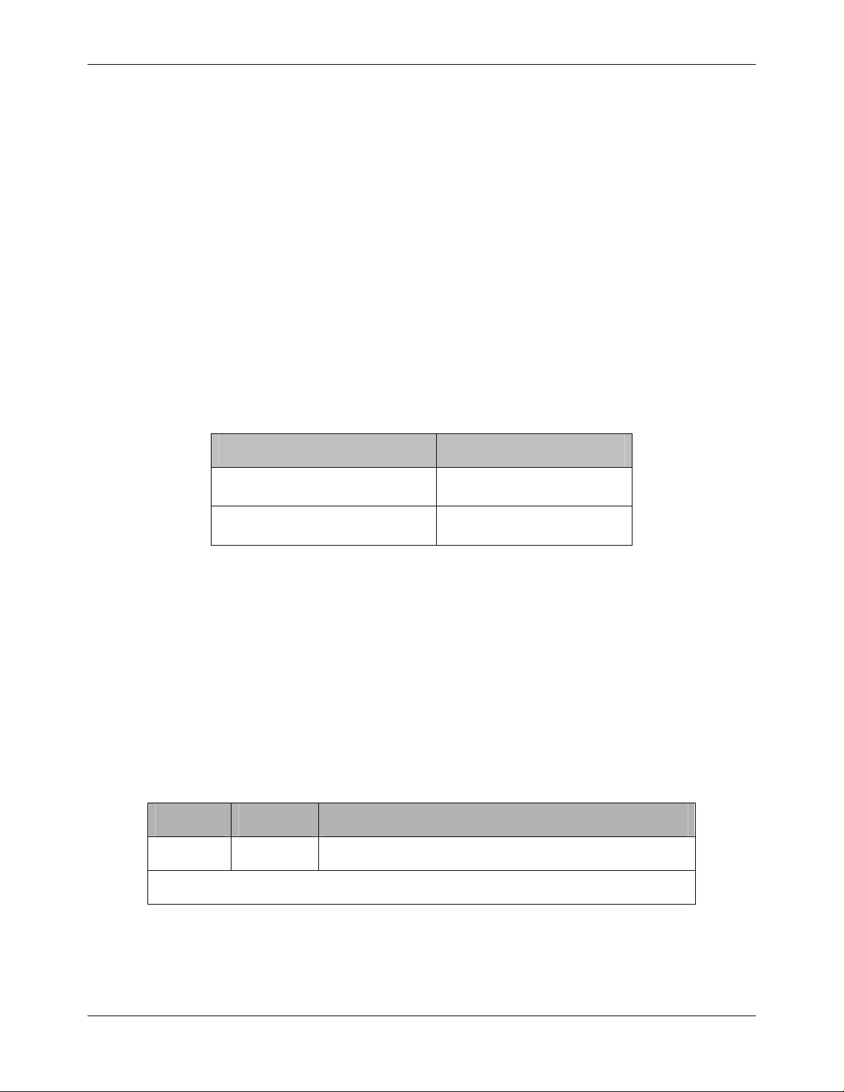
Table 2
-1:Temperature/Humidity Requ
irements
2.1.4
Cleanliness Requirements:
Dust is a big hazard to the safe operation of switches. Indoor dust falling on the switch body can cause
electrostatic adsorption to make poor contact of metal
connectors or metal contacts. Especially when the
indoor relative humidity is lower, electrostatic adsorption is easily formed, which will not only affect equipment
service life, but also easily lead to communication failure.
Table 2
-
2: Dust Content Requir
ements in Switch Room
Substance
Unit
Concentration limit
DUST
Particle/m3
≤ 3 X 10⁴ (No visible dust on the tabletop for three days)
Note: The dust particle size is
≥ 5μmBesides dust, there are rigorous limits on the content of harmful substances that can accelerate the
corrosion and aging of metals, such as salts, acids, a
nd sulfides in the air in the equipment room, and the
equipment room must be protected against ingression of harmful gases such as SO2, H2S, NH3, and
Item
9171 Series
Temperature
0~5
0CHumidity
10%~95%

9171 Installation Guide
Proprietary & Confidential
Canoga Perkins Metro Ethernet Routing Switch
Page8of
26
Cl2. For the specific requirement, see
Table
2-3
.
Table
2-3
Harmful Gas Threshold in th
e Equipment Room
Gas
Maximum concentration (mg/m3)
SO2
0.2
H2S
0.006
NH3
0.05
Cl2
0.01
2.1.5
Electromagnetic Susceptibility
Switches may be affected by the interferences from outside the system, which will have an effect on devices
through conduction of c
apacitance coupling, inductive coupling, electromagnetic wave radiation, common
impedance (including ground system) coupling and wires (power wire, signal wire and output signal wire, etc.).
The following attention should be paid to:
AC power supply system
is TN system, and AC power socket should be single
-
phase 3
-
wire outlet
with protective earth (PE) so that filter circuit on devices can effectively filter interference from
electric
grid
.
Places where switches work should be kept away from strong
-
power ra
dio transmitting station, radar
transmitting station, high
-
frequency high
-
current devices.
Electromagnetic shielding should be adopted when necessary,
i.e
. interface cables use shielded
cables.
Interface cables are required to be arranged indoors instead o
f outdoors to prevent signal ports of
devices from being damaged by
over voltage
and
over current
generated from lightning.
2.1.6
Laser Use Safety
9171
series of routing switches are Class 1 laser devices.
Do not stare at the optical interfaces directly when th
e optional optical interfaces of
9171
series of
routing switches are in operating mode, since light beam emitting from fiber has high energy which
may be harmful to retina.

9171 Installation Guide
Proprietary & Confidential
Canoga Perkins Metro Ethernet Routing Switch
Page9of
26
2.1.7
Installation Tools
Prepare the following tools before installation:
Flathead screw
drivers
Phillips screwdrivers
ESD
-
preventive wrist strap
Note:
The installation tools are not provided with
9171
Series Routing Switch
2.2
Installation
2.2.1
Installing Device onto Rack
9171
series of switches can be installed in a 19” standard rack in the fol
lowing way:
Installation of Front Hangers Coupling with Tray
Note: Front hangers are only used to fix switches, but unable to bear the weight.
Fig. 2
-
1: Appearance Sketch Map of Front Hangers
Description:
(1)
Screw hole for fixing front hangers a
nd rack (choose M6 screw)
(2)
Screw hole for fixing front hangers and switch
Installation Method:
Installation process of using front hangers coupling with tray:
a.
Wear ESD
-
preventive wrist strap
, and check the grounding and stability of rack.
b.
Fix the tra
y to a proper position of rack horizontally.

9171 Installation Guide
Proprietary & Confidential
Canoga Perkins Metro Ethernet Routing Switch
Page10of
26
c.
Take out screw (complete package with front hangers), and install one end of the front hangers
on switch, as shown in Fig. 2
-
2.
Fig. 2
-
2: Installation Sketch Map of Front hangers
d.
Place switch on the tray hor
izontally, push it slightly into the rack along the tray, and fix the other end
of front hangers upon the front hold strip of rack using screw and its matching floating nut.
Fig. 2
-
3: Installation Sketch Map of Front Hangers Coupling with Tr
ay
Front Panel
Front Hangers
Front Hangers

9171 Installation Guide
Proprietary & Confidential
Canoga Perkins Metro Ethernet Routing Switch
Page11of
26
2.2.2
Installing Device o
nto Desktop
In many cases, users do not have a standard 19” rack, so people often place switches on a cleaning working
platform. Such operation is relatively simple, and the only following aspects should be concerned during
operation
:
Ensure the working platform is stable and well
grounded
.
A 10 cm space around switch is left for heat dissipation.
Do not place heavy objects on switches.
2.2.3
Installation and Removal of Power Module
Installation Process:
The power modules for
9171
series o
f routing switches are pluggable. Installation process of power modules
is as follows:
Step 1:
Wear ESD
-
preventive wrist strap
, and confirm that the anti
-
static wrist strap is well earthed.
Step 2: Maintain correct up
-
down direction of power module (in lin
e with the positive direction of
characters, if turned upside down, the power module can not be inserted to the end due to structural
limit specially designed inside chassis), grip the handle on the front end of power module to be
installed with one hand a
nd support the bottom of power module with another hand, and insert the
power module by smoothly sliding along the power slot until the plug of power module comes into full
contact with the socket inside chassis.
Step 3: Tighten up the fastening screws on
the left and right sides of power module with a cross
-
head
screwdriver.
Removal Process:
The power modules for
9171
series of routing switches are pluggable. Removal process of power modules is
as follows:
Step 1: Wearing anti
-
static wrist strap, and conf
irm that the anti
-
static wrist strap is well earthed.
Step 2: Disconnect all power connectors of switches.
Step 3: Undo the fastening screws on the left and right sides of power module with a cross
-
head
screwdriver.
Step 4: Grip the handle on the front en
d of power module to be installed with one hand and press on
the top switch with another hand, and pull out the power module by smoothly sliding along the power
slot until the plug of power module is completely separated from the socket inside chassis.
N
ote: Fastening torque should not be more than 0.4 Nm when fastening screws on both sides of the
power module are screwed down using a screwdriver or electric screwdriver.

9171 Installation Guide
Proprietary & Confidential
Canoga Perkins Metro Ethernet Routing Switch
Page12of
26
2.3
Power Wire and Grounding Connection
2.3.1
AC Power Wire Connection
AC Power Socket (recomme
nded)
It is recommended that users use single
-
phase three
-
wire outlets with neutral point connectors or
multifunction microcomputer outlets. The neutral points of power must be grounded reliably in a building.
Generally, in wiring of building construction,
the power neutral points of electrical supply system in such
a building have been buried under the earth, so users need to confirm the power has been grounded.
AC Power Wire Connection
Step 1: Connect one end of the
ground
wire on enclosure included in a
switch to the
grounding
screw on back panel of the switch, and the other end is
properly grounded
.
Step 2: Insert one end of the power wire of the switch into the outlet on back panel of the
cabinet, and the other end into a
n
AC power outlet.
Step 3: Tur
n on the power switch, and check if the power indicator on front panel of the switch is
bright, which indicates that power connection is correct.
Note: The
ground
wire must be connected before switches are powered on.
2.3.2
Grounding Connection
A noise filte
r is connected on the power input of switch, whose central
grounding
is connected directly to
the cabinet, which is called enclosure
grounding
(that is PE). This cabinet must be well grounded to
enable the safe flow of influence electricity and leakage int
o the earth and increase the
anti-electromagnetic interference of switch.
Correct Way of Grounding is as follows:
Connect one end of the yellow and green PE cable of switch to the terminal of grounding bar and screw
up the fastening nut when there is a gr
ounding bar in the installation environment of Ethernet switches.
Note: it is an incorrect option to be grounded with fire mains and a lightning rod in a building, so the
ground wires of Ethernet switches should be connected to the works in switch room an
d ground
ed
.
9171 Installation Guide
Proprietary & Confidential
Canoga Perkins Metro Ethernet Routing Switch
Page13of
26
Fig. 2
-
5: Grounding Installation Sketch When A Grounding Bar is in Switch Room
Description:
(1)Power input of switch
(2)
Ground terminal
of switch
(3)
Protective grounding cable
(4)
Grounding bar of switch room
When there is n
o grounding bar in the installation environment of Ethernet switches, if a mud field is nearby
and grounding electrodes are permitted to bury, angle steel or steel
tube
not less than 0.5 m in length may be
used to directly drive into the ground. At this po
int, the yellow
-
green PE cables of Ethernet switches should be
connected to the angle steel (or steel pole) by welding, and the soldered joint should be treated with
preservatives.
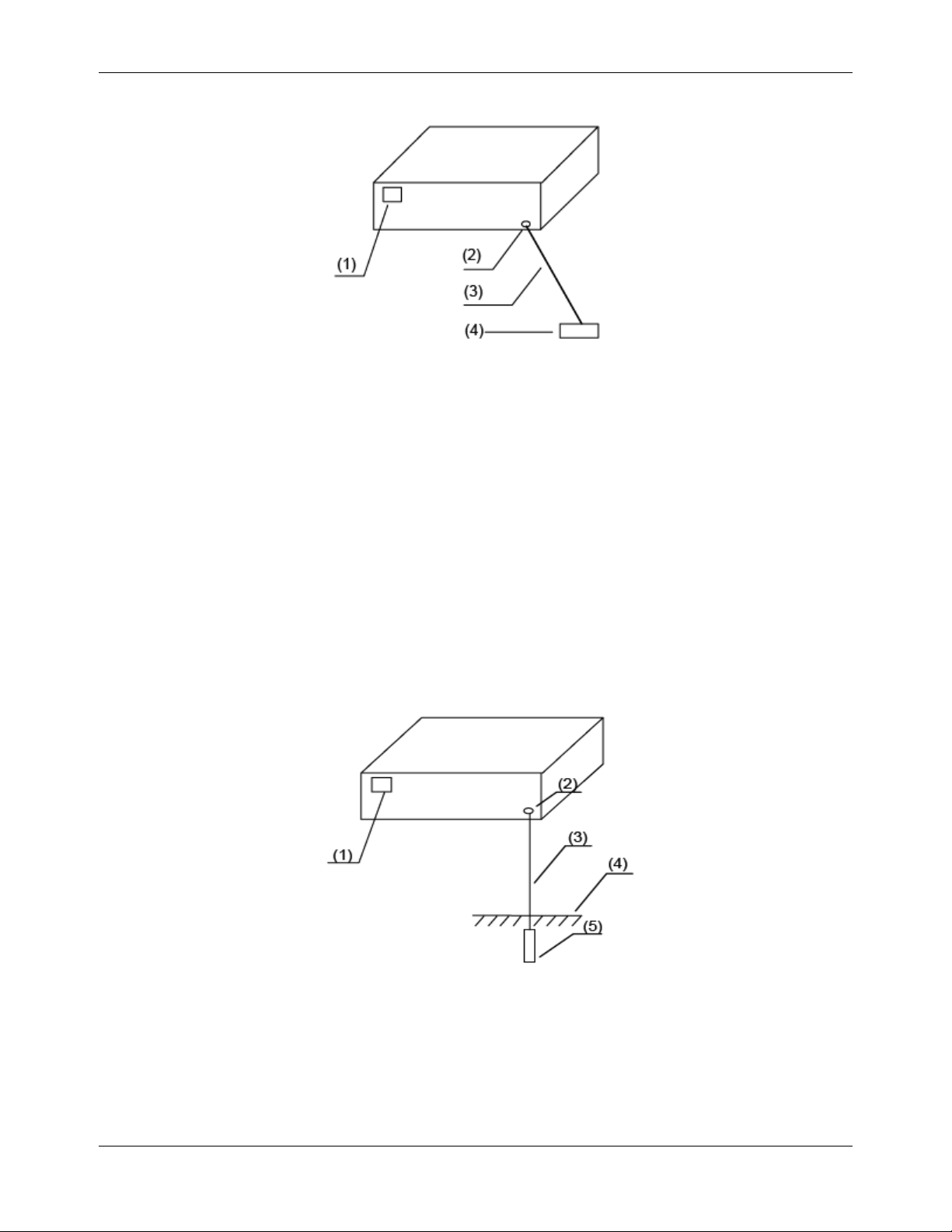
Fig. 2
-
6:Grounding the device through a grounding strip
Description:
(1)Power input of switch
(2)
Ground terminal
of switch
(3)
Protective grounding cable
(4)
Ground
(5)
Angle steel

9171 Installation Guide
Proprietary & Confidential
Canoga Perkins Metro Ethernet Routing Switch
Page14of
26
When there is no grounding bar in the installation environment of Ethernet switches and grounding electrodes
are not permitted to bu
ry according to the conditions, if Ethernet switches are supplied with AC power, they
can be grounded through PE cables of AC power. At this point, PE cables of AC power should be confirmed
well grounded in the power distribution room or on AC supply trans
former side.
Fig. 2
-
7: Grounding Installation Sketch Using AC PE Cable
Description:
(1)
Power input of switch
(2)
Ground terminal of switch
(3)
Power transformer
(4)
PE
(5)3-
core ca
ble used in AC power connection
(6)
Switch
2.3.3
Post
-
Insta
llation Checking
Check if selected power agrees with the identified power of switch:
Check if the ground wire is connected.
Check if the connections between configured cables and power input cables are correct.
Check the interface cables are arranged indoo
rs instead of outdoors, if some cables are arranged
outdoors, check if they are connected with a
n
AC power lightning protection strip and network port
lightning protector.
9171 Installation Guide
Proprietary & Confidential
Canoga Perkins Metro Ethernet Routing Switch
Page15of
26
Chapter 3
Fiber Interface Module and Cable
Connection Description
3.1
Interface Module Descriptio
n
3.1.1
10/100/1000 Ports
Instruction:
10/100/1000 Ethernet interface can use RJ
-
45 connectors. Its maximum transmission distance is 100m. The
transmission of 100Base
-
TX and 1000 Base
-
T needs to use CAT 5 or enhanced CAT 5 twisted pair wires, or
CAT 6 non
-
unshie
lded twisted pair wires. While the transmission of 10 Base
-
T can use CAT 3 or CAT 4
twisted pair wires.
By default, 10/100/1000M auto
-
negotiation are enabled for RJ45 connectors for
9171
Series Routing Switch.
By this setting, when two switches are connect
ed, the switches can automatically negotiate work environment
and parameters to be used in automatic configuration. If one switch does not support this feature, network
administrators or related personnel need to conduct configurations manually. See Config
uration Manual for
specific manual configuration methods.
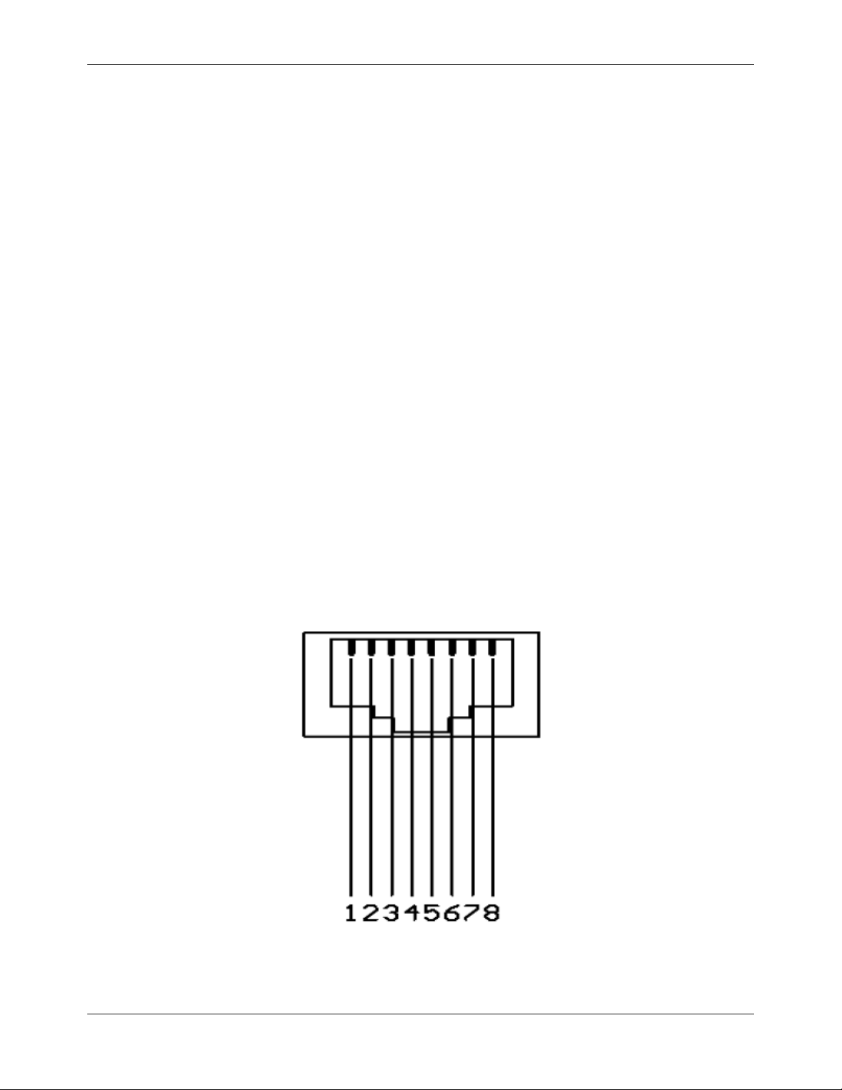
Definition of RJ45 Pins As Shown
in Figure 3
-1:
Fig. 3
-
1: Sketch Map of RJ
-
45 Connector Pins

9171 Installation Guide
Proprietary & Confidential
Canoga Perkins Metro Ethernet Routing Switch
Page16of
26
Table 3
-1Definition of Ethernet RJ45 Port Straight Through Line:
Pin No.
Descri
ption
Description
Pin No.
1
TX+
RX+
1
2TX-RX-
2
3
RX+
TX+
3
4
N/A
N/A
4
5
N/A
N/A
5
6RX-TX-
6
7
N/A
N/A
7
Through
Cable
8
N/A
N/A
8
Table 3
-2Definition of Ethernet RJ45 Port Cross
-
Over Line:
Pin No.
Description
Description
Pin
No.
1
TX+
RX+
3
2TX-RX-
6
3
RX+
TX+
1
4
N/A
N/A
4
5
N/A
N/A
5
6RX-TX-
2
7
N/A
N/A7Cross
over Cable
8
N/A
N/A
8
You may refer to the following standard line sequence for making straight
-
through line and cross
-
over
line:

9171 Installation Guide
Proprietary & Confidential
Canoga Perkins Metro Ethernet Routing Switch
Page17of
26
Fig. 3
-
2: Ethernet Line Seq
uence
3.1.2
Ethernet Port
9171
series of routing switches are integrated with out
-of-
band Ethernet ports whose interfaces are 100
Base
-
TX or 10 Base
-
T. It is recommended to use the net line included.
3.1.3
Console Port
Console port uses an 8
-
pin RJ
-
45 connector. When
connecting the console port of switch to a computer,
we need an RJ
-45-to-DB-
9 adapter cable. It is recommended to use the serial line enclosed in the
installation package.

Chapter 4
Initial Power
-
on & Start
-
up of Switch
4.1
Building Configuration Platform and
Connectin
g Cable:
Fig. 4
-
1: Building Local Configuration Platform Through Console Port
Step 1: Connect DB
-
9 hole
-
type plug of configuration cable to the serial port for configuring switch.
Step 2: Connect RJ
-
45 end of configuration cable to the console port of switch.
4.2
Setting Terminal Parameter
Step 1: Turn on PC and run emulator program
(
Windows system has its own
hyper terminal)
.Step 2: Set terminal parameters (take the
hyper
terminal setting of Windows XP as an example).
Parameter requirements: baud rate: 9600, data bit: 8, parity: no, stop bit: 1, flow control: NA,
selecting termin
al emulation: VT100. Specific method is as follows:
Click "Start"
-
"Program"
-
"Attachment"
-
"Communication"
-"Hyper
Terminal" to
run
Hyper
T
erminal window
and establish a new connection, then a connection description interface will pop up as shown in F
ig. 4-2.
Fig. 4
-
2: New Connection

9171 Installation Guide
Proprietary & Confidential
Canoga Perkins Metro Ethernet Routing Switch
Page19of
26
Fig. 4
-3Connection Port Setting
Fig. 4
-
4 Port Communication Parameter Setting
4.3
Switch Power
-
on
After the swi
tch is powered on and starts up, self
-
check information on equipment will display on the terminal.
Users are prompted to type Enter after self
-
check, then command line DOS prompts (such as
(
CanogaPerkins
)) will appear.
Type a command, configure Ethernet sw
itches or view the running state of Ethernet switches. Enter "?"
whenever you need a help. See the subsequent chapters of this manual for specific configuration commands.

Chapter 5
Switch Software Loading
The traditional switch software loading is serial loading, b
ut it is slow and time
-
consuming, and it can not
realize remote loading and is inconvenient for operation. To address these problems, TFTP module is
introduced to switch to facilitate software loading and file download via Ethernet. Specific operations are
as
follows:
a.
Enter uBoot operation mode
To enter uBoot operation mode, press the combined key Ctrl + B during the switch startup when Press ctrl + b
to stop autoboot: is prompted; startup information is as follows:
Restarting system
U-Boot 1.1.4
9171
v1.1
(Nov 19 2007
-
16:11:08)
MPC8247 Reset Status:
MPC8247 Clock Configuration
-
Bus
-to-
Core Mult 3.5x, VCO Div 2, 60x Bus Freq 30
-
85 , Core Freq 100
-
300-dfbrg 1, corecnf 0x1e, busdf 3, cpmdf 1, plldf 0, pllmf 5
-
vco_out 400000000, scc_clk 100000000,
brg_clk 25000000
-
cpu_clk 350000000, cpm_clk 200000000, bus_clk 100000000
-
pci_clk 33333333
CPU: MPC8247 (HiP7 Rev 14, Mask 1.0 1K50M) at 350 MHz
Board: CTC8247 (PCI Agent Mode)
I2C: ready
DRAM: 256 MB
In: serial
Out: serial
Err: se
rial
Net: FCC1 ETHERNET, FCC2 ETHERNET [PRIME]
Press ctrl+b to stop autoboot: 3 0
–-Press Ctrl+B to enter uBoot operation mode
b.
Identify a PC as loading server, connect the administration port of switch and the PC with net line;
set IP address of the PC
and administration IP address of the switch for the same network segment;
specific operations are as follows:
Use help open_all command to open all commands;
Use the command setenv ipaddr address to set the administration IP address of the switch; the
swit
ch will copy image files to the switch from TFTP server using this address;
Use the command setenv serverip address to set the IP address of TFTP server; the switch will
copy image files from this TFTP server;
Use the command ping to check if the switch co
mmunicates with the loading server;
Can use the command printenv to view the current environment variables of switch;
Can use the command saveenv to save the current environment variables of switch to EPROM;
Can use reenv command to restore the environment
variables of switch to default value.
c.
Run TFTP Server program on PC as a server, and set the directory where loading files are located;
uBoot file supposed to be upgraded is u_boot_v1.0.bin;
d.
Run the command
upgrade_uboot u_boot_v1.0.bin
to upgrade uBoot;
here the filename is
u_boot_v1.0.bin;
e.
Run the command
reset
to
complete
the upgrade of
uBoot.

9171 Installation Guide
Proprietary & Confidential
Canoga Perkins Metro Ethernet Routing Switch
Page21of
26
Chapter 6
Upgrade of Operating System
9171
series of Ethernet switches can support new features and enhance system performance without
replacing hardware by upgrading the
operating system.
Fig. 6
-
1: Upgrade Operating System
a.
Copy the upgrading mirror to switch
In the privilege mode of switch, use the command COPY to copy the mirror files on TFTP server
to the boot directory of switch flash;
Swtich#copy tftp://10.10.29.160/
CanogaOS
-
v1.2.5.fcs1
-
9171
.r.bin
flash:/boot/CanogaOS
-
v1.2.5.fcs1
-
9171
.r.bin
When copying, check if the switch has enough space; if the space is not enough, you can delete
redundant mirror.
b.
Set the mirror that will be loaded when switch starts next time
Aft
er copying the mirror to a relevant directory of switch, you can use the command boot to set
the mirror that will be loaded when switch starts next time;
Switch(config)#boot system flash:/boot/CanogaOS
-
v1.2.5.fcs1
-
9171
.r.bin
c.
View the mirror that will be lo
aded when switch starts next time
After setting the mirror that will be loaded when switch starts next time, you can use the command
SHOW
to check if the setting is valid;
Switch#show boot images
System image files list:
Current boot image version:
9171
-1.2(5), fcs1

9171 Installation Guide
Proprietary & Confidential
Canoga Perkins Metro Ethernet Routing Switch
Page22of
26
Create Time Version File name
======================================================================
2008
-01-
23 10:53:43
9171
-
1.2(4), beta3 CanogaOS
-
v1.2.4.beta3
-
9171
.r.bin
* 2008
-01-
27 10:08:38
9171-
1.2(5), fcs1 CanogaOS
-
v1.2.5.fcs1
-
9171
.r.bin
d.
Among them, the files marked with * are image files that will be loaded when switch starts next time.

Chapter 7
Maintenance and Troubleshooting
7.1
Loading Failure Processing:
After loading fails, the system will ke
ep running in the original version. At this time, users should re
-
check if
physical port connections are good firstly. If some ports are not connected, then re
-
connect them to ensure
that physical connections are correct, and begin re
-
loading. If physical
connections are correct, then check the
loading process information displayed on the super terminal to verify if there are input errors. If there are input
errors, correct them and re
-
load. For example, when using TFTP protocol, we enter incorrect IP addre
sses of
Server and Switch, name of loading software, do not specify the correct working path of correct TFTP server
and so on; if physical connections are good, and there are no input errors in the loading process but the
loading fails finally, please cont
act agents for help.
7.2
User Password Lost
If system password is lost or forgotten, the following method can be used to reset password:
Enter uBoot operation mode; see Chapter 5 for how to enter;
Input boot_flash_nopass command to start system in uBoot mode;
Note: After using boot_flash_nopass command, system will clear up the startup
-
config files; before
starting this operation, the startup
-
config files will be stored in flash: / startup
-
config.conf.old file.
7.3
Power System Troubleshooting:
Switch can judge
if its power system is faulty according to the PWR indicator on the front panel: when power
system works normally, the PWR indicator shall always keep lighting; when the PWR indicator is off, please
check if:
The power line of switch is connected correctl
y.EPS of switch matches the power required by switch
.
7.4
Configuration
System
Troubleshooting:
After the switch is powered on, if system is normal, the startup information will be displayed on the
configuration terminal; If the configuration system is fault
y, the configuration terminal may display no
information or hashes.
No information on the terminal: After power
-
on, if no display information on configuration terminal
appears, please check if:

9171 Installation Guide
Proprietary & Confidential
Canoga Perkins Metro Ethernet Routing Switch
Page24of
26
The power is normal.
The cable of configuration port (Console)
is properly connected.
If no problems have been found after the above checks, it is possible that configuration cable is
faulty or the parameter setting of terminal (such as super terminal) are incorrect, please check
accordingly.
Troubleshooting for the
terminal displaying hashes:
If the configuration terminal displays hashes, it is probable that the parameter setting of terminal (such as
super terminal) are incorrect Please confirm the parameter setting of terminal (such as super terminal): baud
rate: 9
600, data bit: 8, parity: no, stop bit: 1, flow control: NA, selecting terminal emulation: VT100

9171 Installation Guide
Proprietary & Confidential
Canoga Perkins Metro Ethernet Routing Switch
Page25of
26

9171 Installation Guide
Proprietary & Confidential
Canoga Perkins Metro Ethernet Routing Switch
Page26of
26
CANOGA PERKINS CORPORATION
20600 Prairie Street
Chatsworth, California 91311
-
6008 USA
Phone: (818) 718
-
6300 FAX: (818) 718
-
6312
Web Site: www.cano
ga.com
Email: fiber@canoga.com
 Loading...