


 Loading...
E d g e A c c e s s
9145E NID Software
Version 4.10
User Manual
NOTICE
Canoga Perkins has prepared this user’s manual for use by customers and Canoga Perkins personnel as a guide for the proper installation, operation and/or maintenance of Canoga Perkins equipment. The drawings, specifications and information contained in this document are the property of Canoga Perkins and any unauthorized use or disclosure of such drawings, specifications and information is prohibited.
Canoga Perkins reserves the right to change or update the contents of this manual and to change the specifications of its products at any time without prior notification. Every effort has been made to keep the information in this document current and accurate as of the date of publication or revision. However, no guarantee is given or implied that the document is error free or that it is accurate with regard to any specification.
CANOGA PERKINS CORPORATION
20600 Prairie Street
Chatsworth, California 91311-6008
Business Phone: (818) 718-6300
(Monday through Friday 7 a.m. - 5 p.m. Pacific Time) FAX: (818) 718-6312 (24 hrs.)
Web Site: www.canoga.com E-mail: fiber@canoga.com
Copyright © 2012 Canoga Perkins Corporation
All Rights Reserved
EdgeAccess®
9145E NID Software User Manual
Product Number 6913655
September 2012
Rev E
EdgeAccess and Canoga Perkins are registered trademarks of Canoga Perkins Corp.
To find Technical Advisories and Product Release Notes, go to the Canoga Perkins web site at http://www.canoga.com.
9145E NID Software User’s Manual
Preface
About this Manual
This manual provides instructions on the configuration and operation of the 9145E Network Interface Device (NID) Version 4.1 software. The 9145E NID can be managed through the VT100 terminal using the RS-232 serial port, through an Ethernet connection using a Telnet terminal emulation program, or by using SNMP.
How this Manual is Organized
This document contains both information and procedures organized in roughly chronological order. Starting from an introduction to the 9145E software, it continues with system requirements, initial implementation, and continued operation.
The document contains the following chapters:
•Chapter 1, Introduction to the 9145E Software provides basic information about the software and navigation.
•Chapter 2, Getting Started describes how to set up and get started using the 9145E.
•Chapter 3, System Configuration describes how to configure the 9145E management features.
•Chapter 4, Diagnostics describes how to configure and perform routine network diagnostics.
•Chapter 5, Port Information describes the User port, Network port, Multipurpose port, and the Management UTP port.
•Chapter 6, System Alarm & Logs describes how to configure System Alarms and System Logs.
•Chapter 7, Utilities describes system utilities.
•Chapter 8, Software Upgrade describes how to upgrade the NID software.
•Chapter 9, Link OAM describes the Operations, Administration, and Maintenance functions, such as remote fault indication and remote loopback control, as specified by the IEEE 802.3ah standard.
•Chapter 10, CoS Configuration describes how to enable or disable Class of Service support, which includes classification, queuing, scheduling and queue management functions for the 9145E.
•Chapter 11, Service OAM describes how to detect, isolate, and report connectivity faults that span networks comprised of multiple LANs, and monitor the performance of connections.
•Chapter 12, Configuring EVC describes Ethernet Virtual Connection (EVC) functionality and the entities required for its configuration.
3
9145E NID Software User’s Manual
•Chapter 13, Bandwidth Profiling describes 9145E bandwidth profiling.
New in this Revision
The following features are new in this release of the manual:
•Service Activation
•Y.1731 Performance Monitoring
•Double tagging on the management VLAN
•QoS: Policing and Shaping
For more details on features added in this release, refer to the Software Release Notes.
Contacting Technical Support
Contact Canoga Perkins technical support (1-800-360-6642), or your 9145E support supplier, for hardware and software support, including product repairs and part ordering. Please have the following information available:
•NID model and serial number
•NID software version
•Detailed description of the problem and specific questions
•Details from messages in system log (if available)
•Description of any troubleshooting steps already performed and results
Document Feedback
Because quality is our first concern at Canoga Perkins, we have made every effort to ensure the accuracy and completeness of this document. However, if you find an error or an omission, or you think that a topic needs further development, we want to hear from you. Forward your feedback to: techsupport@canoga.com
Provide the title and version number and as much detail as possible about your issue, including the topic heading, page number, and your suggestions for improvement.
4
9145E NID Software User’s Manual
Contents
Preface ....................................................................................................... |
|
iii |
About this Manual ..................................................................................... |
iii |
|
How this Manual is Organized.................................................................................. |
iii |
|
Conventions Used in this Manual............................................................................. |
iv |
|
New in this Revision ................................................................................................. |
iv |
|
Contacting Technical Support .................................................................................. |
iv |
|
Document Feedback ................................................................................................. |
v |
|
Chapter 1. |
Introduction .......................................................................... |
1 |
About the 9145E Software ....................................................................................... |
1 |
|
Management Access................................................................................................ |
1 |
|
Management Security Features ............................................................................... |
1 |
|
Three Levels of Security........................................................................................... |
2 |
|
Feature Access Level Configuration ........................................................................ |
2 |
|
Chapter 2. |
Getting Started ..................................................................... |
3 |
Configuring Terminal Management .......................................................................... |
3 |
|
Setting Up SNMP Network Management ................................................................. |
4 |
|
About MIBs........................................................................................................................ |
4 |
|
v
9145E NID Software User’s Manual |
|
9145E Set-up .................................................................................................................... |
4 |
Management User Interface..................................................................................... |
4 |
Login......................................................................................................................... |
5 |
Main Menu................................................................................................................ |
6 |
Supported MIBs........................................................................................................ |
8 |
Chapter 3. System Configuration .......................................................... |
9 |
System Configuration Menu ..................................................................................... |
9 |
IP/SNMP Agent Configuration................................................................................ |
10 |
Management IP Configuration ........................................................................................ |
10 |
Configuring Tunnel Management .............................................................................. |
12 |
Auxiliary IP Configuration................................................................................................ |
13 |
Host Table....................................................................................................................... |
15 |
Adding or Editing a Managing Host IP ...................................................................... |
16 |
Trap Table....................................................................................................................... |
17 |
Adding or Editing a Trap Table ................................................................................. |
17 |
Deleting a Trap Table................................................................................................ |
22 |
Trap Configuration.................................................................................................. |
22 |
Security Configuration ............................................................................................ |
24 |
Password Configuration .................................................................................................. |
24 |
Lockout/Logout Configuration ......................................................................................... |
26 |
Account Configuration ............................................................................................ |
27 |
Three Levels of Security ................................................................................................. |
27 |
Add or Edit an Account ................................................................................................... |
28 |
Delete an Account........................................................................................................... |
30 |
System Information ................................................................................................ |
31 |
RADIUS Client........................................................................................................ |
32 |
RADIUS client configuration............................................................................................ |
32 |
vi
|
|
9145E NID Software User’s Manual |
SNTP Client Configuration ..................................................................................... |
34 |
|
SYSLOG Client Configuration ................................................................................ |
36 |
|
Hardware Information............................................................................................. |
37 |
|
Chapter 4. |
Diagnostics ......................................................................... |
41 |
Diagnostic Functions .............................................................................................. |
41 |
|
Loopback Setup ..................................................................................................... |
41 |
|
Latency/Jitter Test .................................................................................................. |
42 |
|
PING Generation.................................................................................................... |
45 |
|
VLAN Loopback ..................................................................................................... |
47 |
|
Cable Diagnostics .................................................................................................. |
51 |
|
Network Performance............................................................................................. |
53 |
|
Throughput Testing................................................................................................. |
97 |
|
SOAM Based Diagnostics..................................................................................... |
100 |
|
Service Activation Testing..................................................................................... |
104 |
|
Chapter 5. |
Port Information ............................................................... |
129 |
Port Description.................................................................................................... |
129 |
|
Link Status............................................................................................................ |
130 |
|
Port Configuration ................................................................................................ |
131 |
|
Hardware Information.................................................................................................... |
132 |
|
Functional Configuration ............................................................................................... |
133 |
|
VLAN Configuration ...................................................................................................... |
134 |
|
VLAN Rules............................................................................................................. |
135 |
|
Port VLAN ID Translation Table .............................................................................. |
137 |
|
P-Bit Translation Table............................................................................................ |
139 |
|
C-VLAN/PCP Policers.............................................................................................. |
140 |
|
vii
9145E NID Software User’s Manual |
|
|
Port Filters..................................................................................................................... |
142 |
|
L2CP Service Frame Processing Options in MEN .................................................. |
142 |
|
How the 9145E Handles L2CP Service Frames with Port Filters ........................... |
143 |
|
Filtering Cisco Proprietary Protocols ....................................................................... |
144 |
|
Setting Port Filters................................................................................................... |
144 |
|
L2CP Port Filters...................................................................................................... |
146 |
|
Port Based VLAN Control ............................................................................................. |
148 |
|
Port Level Policers......................................................................................................... |
149 |
|
Layer 2 Statistics .................................................................................................. |
151 |
|
Layer 2 Counter Definitions.................................................................................. |
152 |
|
RMON Group 1 Statistics ..................................................................................... |
155 |
|
Chapter 6. System Alarms & Logs .................................................... |
157 |
|
System Alarms ..................................................................................................... |
157 |
|
System Log .......................................................................................................... |
158 |
|
Chapter 7. |
Utilities .............................................................................. |
161 |
Utilities Menu........................................................................................................ |
161 |
|
Set Date and Time ............................................................................................... |
161 |
|
Reset Configuration To Default ............................................................................ |
162 |
|
Change Password ................................................................................................ |
162 |
|
VT100 Baud Rate................................................................................................. |
162 |
|
PING Generation.................................................................................................. |
163 |
|
Static ARP Table .................................................................................................. |
163 |
|
Dynamic ARP Table ............................................................................................. |
164 |
|
License Manager.................................................................................................. |
165 |
|
Chapter 8. |
Software Upgrade............................................................. |
167 |
Flash Memory....................................................................................................... |
167 |
|
viii
|
9145E NID Software User’s Manual |
Software Reset..................................................................................................... |
167 |
Swap Bank and Reset.......................................................................................... |
167 |
Swap Bank After Download and Reset ................................................................ |
168 |
Get Software Upgrades with TFTP ...................................................................... |
169 |
Hardware Reset..................................................................................................... |
170 |
Software Upgrades Using FTP or SFTP .............................................................. |
170 |
Chapter 9. Link OAM........................................................................... |
173 |
Operation, Administration and Maintenance ........................................................ |
173 |
OAM Control......................................................................................................... |
174 |
OAM Operational Status ............................................................................................... |
174 |
OAM Max PDU Size...................................................................................................... |
175 |
OAM Revision ............................................................................................................... |
175 |
OAM Functions ............................................................................................................. |
173 |
OAM Loopback Status .................................................................................................. |
175 |
OAM Remote Fault ....................................................................................................... |
175 |
OAM Admin State ......................................................................................................... |
176 |
OAM Mode ................................................................................................................... |
176 |
OAM Loopback Command............................................................................................ |
176 |
Process Rx Loopback OAM PDU ................................................................................. |
176 |
FWD Critical Event........................................................................................................ |
176 |
User Interface MIB Objects ........................................................................................... |
176 |
OAM Peer Information.......................................................................................... |
177 |
OAM Statistics...................................................................................................... |
178 |
OAM Event Configuration..................................................................................... |
179 |
OAM Event Log .................................................................................................... |
180 |
Event Log Detail Display ............................................................................................... |
181 |
Display Filter Configuration ........................................................................................... |
181 |
ix
Chapter 10. |
CoS Configuration.......................................................... |
183 |
Class of Service ................................................................................................... |
183 |
|
9145E Queueing Funcitonality............................................................................... |
183 |
|
CoS Support......................................................................................................... |
184 |
|
Classifier Mapping................................................................................................ |
185 |
|
Tagged Packet Classifier Mapping ............................................................................... |
185 |
|
Untagged Packet Classifier Mode................................................................................. |
186 |
|
Untagged Packet Classifier Mapping ............................................................................ |
186 |
|
IP Precedence Mode............................................................................................... |
186 |
|
DSCP Mode ............................................................................................................ |
187 |
|
AF/EF Mode ............................................................................................................ |
188 |
|
Queue Configuration ............................................................................................ |
189 |
|
Enable/Disable a Queue ............................................................................................... |
191 |
|
Queue Size (In 8K-Byte) ............................................................................................... |
191 |
|
Scheduling Scheme ...................................................................................................... |
192 |
|
Weight Parameters ....................................................................................................... |
192 |
|
Early Detect Drop Profiles............................................................................................. |
192 |
|
Early Detect Drop Profile Configuration ...................................................................... |
192 |
|
Queue Statistics ................................................................................................... |
194 |
|
Chapter 11. |
Service OAM ................................................................... |
197 |
Introduction |
........................................................................................................... |
197 |
Service OAM ........................................................................................................ |
197 |
|
SOAM Entities............................................................................................................... |
198 |
|
Optional SOAM Configuration....................................................................................... |
199 |
|
SOAM Functionality with All-to-One Bundling............................................................... |
199 |
|
SOAM Protocols............................................................................................................ |
201 |
|
Typical Service OAM Deployment and Applications ..................................................... |
202 |
|
x
|
|
9145E NID Software User’s Manual |
Typical Configuration Sequence ................................................................................... |
203 |
|
Screen Navigation......................................................................................................... |
204 |
|
SOAM Configuration ............................................................................................ |
205 |
|
Maintenance Domains.......................................................................................... |
209 |
|
Maintenance Associations.................................................................................... |
213 |
|
Maintenance Entity Groups .................................................................................. |
218 |
|
Maintenance End Points ...................................................................................... |
223 |
|
Linktrace Procedures ........................................................................................... |
229 |
|
Loopback Procedures .......................................................................................... |
232 |
|
Maintenance Intermediate Points......................................................................... |
236 |
|
Configure and View SOAM Statistics ................................................................... |
241 |
|
Statistics Display Confirmation............................................................................. |
245 |
|
AIS Configuration ................................................................................................. |
246 |
|
Chapter 12. |
Configuring EVC...................... |
....................................... 249 |
Introduction |
........................................................................................................... |
247 |
EVC Functionality................................................................................................. |
249 |
|
EVC Records ................................................................................................... |
249 |
|
User-to-Network Functionality........................................................................... |
250 |
|
Network-to-User Functionality........................................................................... |
250 |
|
Statistics............................................................................................................ |
|
250 |
Screen Navigation............................................................................................. |
251 |
|
EVC Configuration................................................................................................ |
253 |
|
S-TPID/T-TPID Configuration............................................................................... |
265 |
|
Chapter 13. |
Bandwidth Profiling .................. |
..................................... 267 |
Bandwidth Profiles................................................................................................ |
267 |
|
xi
9145E NID Software User’s Manual |
|
Policers................................................................................................................. |
269 |
Shapers ................................................................................................................ |
270 |
Shaper statistics................................................................................................ |
272 |
Queue size and yellow packet thresholds ............................................................ |
272 |
Configuring Bandwidth Profiles ............................................................................ |
273 |
User to Network Ingress Policers ......................................................................... |
277 |
User to Network Egress Shapers ......................................................................... |
280 |
Clock Rate Granularity ......................................................................................... |
281 |
Color Marking Method .......................................................................................... |
281 |
xii
Introduction |
9145E NID Software User’s Manual |
Management Access
Chapter 1
Introduction
1.0 About the 9145E Software
Building on the industry-leading 10/100/1G 9145 Network Interface Device (NID), the 9145E adds dual mode UTP/SFP ports, a multi-purpose network protection link/NNI Performance Measuring Port, and an Ethernet OOB port to provide out-of-band management. Its larger, faster processor allows advanced features including per VLAN traffic statistics and full 802.1ag CFM support in future releases.
1.1 Management Access
The 9145E can be managed through any of several access ports.
VT-100 Terminal The VT-100 terminal is used to manage the NID locally via the EIA-232 serial port, primarily to perform initial configurations on the NID before it is connected to the network..
Telnet Once the 9145E has been connected to your network, it can be accessed using Telnet. All commands and functions are available using standard Telnet software.
SNMP All commands and functions are also available using an SNMP manager. The 9145E supports SNMP v1/v2c/v3 and many standard MIBs as well as CP proprietary MIBs.
1.2 Management Security Features
The 9145E has comprehensive management access security features, including SNMPv3 authorization, RADIUS, password formatting, and user access controls. You can set values and options within the software that will work with the security protocols on your network. The four network security protocols listed below are supported. In addition, the 9145E provides options to define strong passwords, independent of the security protocols.
SNMPv3 Provides authentication and encryption of management traffic across a network.
Remote Access Dial In User Security (RADIUS) The RADIUS server maintains user account information. At login, the 9145E queries the server which authenticates the username and password and sends a message to the 9145E to allow the login. The RADIUS server can also be set up to require additional authentication information before accepting the user. If the username or password is not valid, the RADIUS server sends a message to the 9145E to disallow the login and reject the user.
1
9145E NID Software User’s Manual |
Introduction |
|
Three Levels of Security |
Secure Shell version 2 (SSH-2) SSH-2 provides authentication and encryption for a secure remote Telnet connection. SSH can be configured to provide unique User Accounts.
Secure File Transfer Protocol (SFTP) SFTP adds encryption to protect uploaded files during the file transfer process, such as for a software update.
1.3 Three Levels of Security
Most Service Provider management networks provision certain access levels to technicians, network administrators, and managers. Offering different access levels to critical applications allows network administrators to keep closer watch on the entire network.
The 9145E allows view-based access to be set up for user interface features and SNMP access. A capabilities file allows views to be defined in an ASCII file and downloaded to the NID. A three-level security system on the 9145E controls all user interface and SNMPv3 access.
All 9145E features require that the user have a certain access level. The logged in user or SNMPv3 manager’s access level is used to validate and control access to the 9145E features. When accessing a menu item or an SNMP object, the user’s access level is checked against the access level required for the feature. If the user’s access level is sufficient, then the access is granted. If the user’s access level is not sufficient, an error message is displayed in the status area, or an SNMP error is returned.
The three access levels are supervisor, operator, and observer.
In the default configuration, the supervisor access level is allowed complete access to all of the 9145E’s features including configuring the 9145E’s security system.
The operator access level is allowed access to the 9145E features except those relating to the 9145E’s security system. This level can be configurable by the administrator.
The observer access level is allowed access to the 9145E features that do not modify the 9145E’s configuration. This level can be configurable by the administrator.
1.4 Feature Access Level Configuration
The assignment of access levels has a default configuration built into the 9145E. Creating and downloading a text file called 9145e.cap to the 9145E can change this assignment, however. This file contains mappings between module features and the access level required to access the feature.
As an example the entry that controls access to the Maximum Frame Size setting looks like maxFrameSize=operator. This entry indicates that to change the Maximum Frame Size, a user’s account must have “operator” access level or greater.
The default 9145e.cap file containing the 9145E built-in security rules is provided with the 9145E release. To modify the security rules, simply modify the provided “9145e.cap” file and download this modified file to the 9145E. The 9145e.cap file is downloaded to the 9145E via the normal FTP/SFTP/TFTP in the same manner as downloading a firmware file to the 9145E. The same file may be downloaded to multiple 9145E's to ensure the same security rules.
If the file 9145e.cap is not downloaded to the 9145E, then the built-in feature to access level mappings in the 9145E are used. If a feature is not present in the file “9145e.cap” that is downloaded to the 9145E, then the built-in feature to access level mapping in the 9145E is used. If errors are found in this file, these errors are displayed in the System log.
2

Getting Started |
9145E NID Software User’s Manual |
Chapter 2
Getting Started
2.0 Configuring Terminal Management
When you use the RS-232 Serial Port for VT-100 sessions, Canoga Perkins suggests that you use HyperTerminal or another type of terminal emulation software on a PC.
NOTE: Microsoft Vista does not include HyperTerminal. If your PC uses the Vista operating system, you will need to install a terminal emulation program.
To set up HyperTerminal on your PC.
NOTE: For details on using MS Windows, refer to your MS Windows documentation.
1.Select Start>All Programs > Accessories > Communications > HyperTerminal.
2.At the Connection Description dialog, select an icon and enter the name for the connection. Click OK.
3.At the Connect To dialog, select the Connect Using menu. Select the COM port and click OK.
4.Select the Port Settings tab from the COM Properties dialog. Make the following selections:
a.Bits per second: 9600 bps
b.Data bits: 8
c.Parity: None
d.Stop bits: 1
e.Flow control: None
6.Click OK.
7.Go to File > Properties > Settings and change the Emulation setting from Auto detect to
VT100.
8.HyperTerminal connects to the system and the VT100 terminal emulation starts.
3

9145E NID Software User’s Manual |
Getting Started |
|
Setting Up SNMP Network Management |
2.1 Setting Up SNMP Network Management
The 9145E communicates with CanogaView or your Network Management Platform either inband, via the User or Network port, or out of band, via the Management UTP port.
2.1.1 About MIBs
To communicate with the 9145E using SNMP, standard Management Information Bases (MIBs) are required on your Network Management Platform. Refer to “Supported MIBs” on page 8 for a list of MIBs.
Additionally, Canoga Perkins Private MIBs are needed on the Management Platform to manage tasks specific to the Canoga Perkins 9145E. The Canoga Perkins Private MIBs are available for download in the Client Support area of the Canoga Perkins web site. Go to www.CANOGA.com then click on Client Support.
NOTE:To log in to the client site or secure site you will need to register using the serial number of the 9145E.
2.1.2 9145E Set-up
Several TCP/IP and SNMP parameters must be configured before you can access the 9145E from CanogaView or your Management Platform. These parameters include TCP/IP Address, Authorized Host List and Privileges. These parameters are initialized using a VT-100 Terminal connected to the RS-232 Serial Port. Refer to “System Configuration Menu” on page 9 for details on configuring these parameters.
2.2 Management User Interface
The Management User Interface for the 9145E provides a menu driven interface for setup, monitoring, and diagnostics. You can access the screens directly by connecting to the serial port of the 9145E or using Telnet.
A typical screen (Figure 2-1) includes standard descriptions and reference designations. Use this and other screens to configure the system, set operational parameters, and verify the system status. All screens use a common method for navigation.
Use the following methods to navigate screens:
•When a menu item is highlighted, press the Space bar to view the options for that item.
•Press Tab to move the highlight to the next column.
•Press Enter to select the highlighted option for a menu item or to go to the next line.
•Press Esc once to cancel an action or to return to the previous screen.
To select an item from a screen menu enter the item number. For example, type 6 and press Enter to select Utilities, as shown in Figure 2-1.
4
Getting Started |
9145E NID Software User’s Manual |
Login
Canoga Perkins Corp. |
Ethernet Network Interface Device |
29-JAN-2012 |
|
Model 9145E - 101 - 3 - 0 V41.70 |
|
|
10:55:13 |
--------------------------------------- |
|
MAIN MENU------------------------------- |
|
MODEL SOFTWARE |
1) |
System Configuration |
|
2) |
Diagnostics |
|
|
VERSION |
|
||
|
|
|
|
3)Port Information
4)System Alarms
5)System Log
|
6) |
Utilities |
MENU |
7) |
Software Upgrade |
|
8)Manage Logged In Users
9)Link OAM
10)CoS Configuration
11)Service OAM
12)EVC Configuration
13)Bandwidth Profile Enforcement
14)Logout
Select [1-14]: |
MESSAGES & |
|
|
|
URGENT STATUS |
------------------------------------Messages----------------------------------- |
|
Figure 2-1 Screen Format
2.3 Login
The first screen is the Login Screen (Figure 2-2). Type your Username and press Enter. The Password prompt will then appear. Type your Password and press Enter. If the Username or Password are incorrect, you will be returned to the Username Prompt and the message Invalid Username/Password entered will be displayed.
CAUTION: The default username and password is admin (lower case). Canoga Perkins strongly recommends you change the default username and password during your initial
configuration session.
5

9145E NID Software User’s Manual |
Getting Started |
|
Main Menu |
Canoga Perkins Corp. |
Ethernet Network Interface Device |
29-JAN-2009 |
9145E - 101 - 1 - 0 V04.10 |
|
11:14:16 |
-------------------------------------- |
LOGIN SCREEN----------------------------- |
|
Please Enter Login Username : admin
Please Enter Login Password : *****
------------------------------------Messages-----------------------------------
Figure 2-2 Login screen
When you successfully log in, the Main Menu (Figure 2-3) opens. Use the Main Menu to access all 9145E functions, including setup, diagnostics, and reports.
Refer to “Account Configuration” on page 29 and “Password Configuration” on page 26 for information about configuring you account and changing your password.
CAUTION: If you lose both your Username and Password, return the unit to Canoga Perkins for Factory Service and reset.
2.4 Main Menu
Following is a brief description of the Main Menu items.
1.System Configuration The System Configuration screen is used to view and set values for system information and TCP/IP management communications parameters.
2.Diagnostics The Diagnostics screen is used to set up various troubleshooting tests, including Loopback, Latency/Jitter, PING tests, VLAN Loopback, or Cable Diagnostic.
3.Port Information The Port Information screen is used to ascertain the current conditions for all ports in the 9145E, to set and view the configuration information for specific ports, check Link Status and Layer 2 Statistics and configure Link Aggregation functionality.
4.System Alarms The System Alarms screen is used to view current alarm conditions.
5.System Log The System Log screen displays a list of recent traps, alarms, and events.
6
Getting Started |
|
9145E NID Software User’s Manual |
||||
Main Menu |
|
|
|
|
||
|
6. Utilities The Utilities screen is used to set-up and display basic functional information. |
|||||
|
|
|
|
|
|
|
|
|
Canoga Perkins Corp. |
Ethernet Network Interface Device |
29-JAN-2012 |
|
|
|
|
Model 9145E-101-3-0 V41.70 |
|
|
10:55:13 |
|
|
--------------------------------------- |
|
|
MAIN MENU------------------------------- |
|
|
|
|
|
1) |
System Configuration |
|
|
|
|
|
2) |
Diagnostics |
|
|
|
|
|
3) |
Port Information |
|
|
|
|
|
4) |
System Alarms |
|
|
|
|
|
5) |
System Log |
|
|
|
|
|
6) |
Utilities |
|
|
|
|
|
7) |
Software Upgrade |
|
|
|
|
|
8) |
Manage Logged In Users |
|
|
|
|
|
9) |
Link OAM |
|
|
|
|
|
10) |
CoS Configuration |
|
|
|
|
|
11) |
Service OAM |
|
|
|
|
|
12) |
EVC Configuration |
|
|
|
|
|
13) |
Bandwidth Profile Enforcement |
|
|
|
|
|
14) |
Logout |
|
|
|
|
|
Select [1-14]: |
|
|
|
|
------------------------------------ |
|
|
Messages----------------------------------- |
|
|
|
|
|
|
|
|
|
Figure 2-3 Main Menu
7.Software Upgrade The Software Upgrade screen is used to download and install new firmware using TFTP, swap firmware banks, and reset the Standard 9145E.
8.Manage Logged In Users The Manage Logged In Users screen is used by the administrator to view current users, and to terminate user sessions when required.
9.Link OAM The OAM screen is used to set, change, and view various link layer operational, administration and maintenance (OAM) functions.
10.CoS Configuration The Class of Service (CoS) Configuration screen is used to enable or disable classification support, and to establish priority to queue mapping, set up queue configuration, create drop profiles, and view queue statistics.
11.Service OAM The Service OAM screen is used to configure Connectivity Fault Management.
12.EVC Configuration The Ethernet Virtual Connection (EVC) Configuration screen is used to configure VLAN Multiplexing.
13.Bandwidth Profile Enforcement The Bandwidth Profile Enforcement screen is used to configure bandwidth profiles for traffic management.
14.Logout Terminates your current session.
7

9145E NID Software User’s Manual |
Getting Started |
|
Supported MIBs |
2.5 Supported MIBs
This section lists all supported MIBs including Standard MIBs and the Canoga Perkins MIBs.
|
Table 2-1. Standard MIBs |
|
|
|
|
|
|
|
mib-2.my |
|
dot3.oam.my |
|
|
|
ifmib.my |
|
ping.my |
|
|
|
rmon.my |
|
rmon2.my |
|
|
|
hcrmon.my |
|
entitymib.my |
|
|
|
Table 2-2. Canoga Perkins MIBs
cp9145estatus.my |
cploopback.my |
cpsntp.my |
|
|
|
cpaccounts.my |
cpmgmtstatus.my |
cpstatus.my |
|
|
|
cpcablediag.my |
cpnpa.my |
cpsysinf.my |
|
|
|
cpcos.my |
cppbvc.my |
cpsyslog.my |
|
|
|
cpdot3oam.my |
cpping.my |
cpsystemlog.my |
|
|
|
cpentitynaming.my |
cpportconfig.my |
cptrapconfig.my |
|
|
|
cpentity.my |
cpportpbittrans.my |
cptraptb.my |
|
|
|
cpfanstatus.my |
cpportvlanrules.my |
cpvlanloopback.my |
|
|
|
cphosttb.my |
cpportvlantrans.my |
cfm.my |
|
|
|
cpifmib.my |
cppowersupply.my |
cpte.my |
|
|
|
cpipconfig.my |
cpradius.my |
cpsa.my |
|
|
|
cplatency.my |
cpsecurity.my |
cp_soam_ext.my |
|
|
|
cplicense.my |
cpsfpstatus.my |
|
|
|
|
8
System Configuration |
9145E NID Software User’s Manual |
System Configuration Menu
Chapter 3
System Configuration
3.1 System Configuration Menu
The System Configuration screen (Figure 3-1) allows you to access the screens that configure various management, IP, security, and alarm settings. The following section describes each item of the System Configuration screen.
Canoga Perkins Corp. |
Ethernet Network Interface Device |
29-JAN-2009 |
|
9145E - 101 - 1 - 0 V04.10 |
|
|
11:20:59 |
---------------------------------- |
|
SYSTEM CONFIGURATION------------------------- |
|
|
1) |
IP/SNMP Agent Configuration |
|
|
2) |
Trap Configuration |
|
|
3) |
Security Configuration |
|
|
4) |
Account Configuration |
|
|
5) |
System Information |
|
|
6) |
RADIUS Client Configuration |
|
|
7) |
SNTP Client Configuration |
|
|
8) |
SYSLOG Client Configuration |
|
|
9) |
Hardware Information |
|
Select [1-9]:
------------------------------------Messages-----------------------------------
Figure 3-1 System Configuration screen
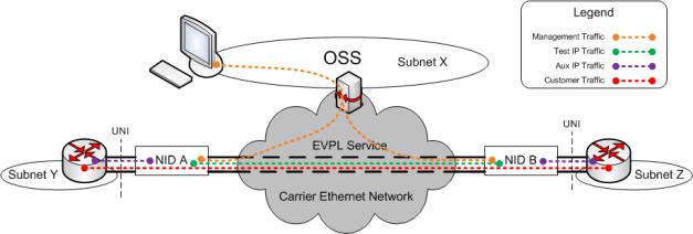
Figure 3-2 shows a logical model for a 9145E NID. The NID consists of a forwarding plane, a control plane, an internal port that connects the two planes and external ports that provide connectivity to other network elements.
9

9145E NID Software User’s Manual |
System Configuration |
|
System Configuration Menu |
Figure 3-2 Logical Model for a NID
The forwarding plane is responsible for processing service frames exchanged between Client and Network Ports, while the control plane is responsible for processing packets carrying messages for administrative control of the 9145E along with synthetic test traffic generated by the NID. A physical internal port provides connectivity between the forwarding and control planes. The port that connects the control plane to the forwarding plane can have multiple logical interfaces. For example, the management agent can be attached to this interface by assigning it an IP Address. Likewise, the Test IP or Aux IP entities can present themselves on this interface by enabling them on the NID and assigning them IP Addresses.
Manager |
This is the management entity of the NID. An IP Address can be user assigned |
|
to the Manager. The Manager is responsible for peering a variety of |
|
management protocols, such as TELNET, SNMP, SFTP and RADIUS, to name |
|
a few. The Manager's IP Address is typically configured as an address on the |
|
Service Provider's management network. The Manager will process any |
|
packet received with this IP Address in the packet's destination address field. |
|
Likewise, the Manager will generate IP packets with this address as its source |
|
address field. |
Test IP |
The Test IP entity generates and peers synthetic test traffic, such as Canoga |
|
Perkins proprietary Latency/Jitter test traffic. The Test IP Address is user |
|
configurable and the entity presents this address on the logical interface. The |
|
Test IP entity will process any packet received with this IP Address in the |
|
packet's destination address field. Likewise, the entity will generate IP packets |
|
with this address as its source address field. |
10
System Configuration |
9145E NID Software User’s Manual |
|
System Configuration Menu |
|
|
Aux IP |
The Aux IP entity can be user assigned to any port on the NID. The user can |
|
|
configure an Aux IP Address for this entity that is not on the Manager's subnet. |
|
In this manner, the Aux IP can be used for diagnostic purposes, by allowing the user to PING subnets not accessible by the Manager IP. The Aux IP entity will process any packet received with this IP Address in the packet's destination address field. Likewise, the entity will generate IP packets with this address as its source address field.
Figure 3-3 Typical Application of the Control Plane Entities
Figure 3-3 shows how these different entities are typically used by a Service Provider. The grey cloud represents the Service Provider's network, with the NIDs placed as the demarcation points of the service (in this example, it is a Carrier Ethernet network delivering an EVPL service to a customer, but it could have been an IP, VPLS, or any other type of service, for that matter).
The NIDs are typically managed via IP over a management VLAN. Each Manager will be assigned an available IP Address by the OSS administrator, and the management VLAN will be configured in each NID. A host on the OSS can then manage each NID by TELNET, or by using an SNMP manager application. This traffic is shown in orange in the diagram.
Let us say the Service Provider wants to monitor the latency and jitter between the UNIs (i.e., between the Client Port of NID A and that of the NID B in Figure 3-3). A Test IP can be setup on each NID in this point-to-point service. The Test IP Addresses chosen must be unique on each NID and on the same subnet. NID A can then generate test traffic (shown in green) out the Network Port to NID B. NID B will receive this test traffic, insert timestamps where appropriate, and send it back to NID A for final processing. In this manner, NID A can test the path and gather precise latency and jitter measurements between the two endpoints.
In addition to monitoring the performance of the service, the Service Provider might also like to monitor the connectivity between the NIDs and the CEs. The Service Provider and the customer can agree on exchanging ICMP Echo Request/Reply messages across the UNI (i.e., the Service Provider and customer agree to allow PINGs to be generated from the NID to the CE). The IP interface on the CE may very well be on a subnet that is different from the Manager (or the Test IP, for that matter). Therefore, the Aux IP can be configured independently with an IP Address and VLAN that provides connectivity to the CE for ICMP messages. The Service Provider can then generate ICMP Echo Requests to the CE, and the CE can reply back with ICMP Echo Reply
11
9145E NID Software User’s Manual |
System Configuration |
|
IP/SNMP Agent Configuration |
messages. If there is no reply from the CE, the Service Provider will know instantaneously that there is a fault in the connectivity between the two network elements.
3.2 IP/SNMP Agent Configuration
The IP/SNMP Agent Configuration screen (Figure 3-4) configures the Management IP, Test IP, and Auxiliary IP settings; and is used to add, edit, or delete Host Table and Trap Table entries.
The Management IP, Test IP, and Auxiliary IP Addresses are used for managing and conducting testing on a TCP/IP network.
|
Canoga Perkins Corp. |
Ethernet Network Interface Device |
29-JAN-2009 |
||
|
9145E-101-1-0 V04.10 |
|
|
|
11:22:37 |
------------------------------- |
|
|
IP/SNMP AGENT CONFIGURATION--------------------- |
|
|
|
|
1) |
Management |
IP Configuration |
|
|
|
2) |
Auxiliary IP Configuration |
|
|
|
|
3) |
Host Table |
|
|
|
|
4) |
Trap Table |
|
|
|
|
|
Select |
[1-4]: |
|
------------------------------------ |
|
|
Messages----------------------------------- |
|
|
|
|
|
|
|
|
Figure 3-4 IP/SNMP Agent Configuration screen
3.2.1 Management IP Configuration
The Management IP Configuration screen (Figure 3-5), is used to configure the Management IP of the 9145E, including the subnet mask, gateway, and management VLAN. It is also used to configure which ports can be used for management access. See your network administrator for information and help with determining the appropriate parameters.
1. Manager IP Address Sets the 9145E Manager IP Address.
Subnet Mask Sets the 9145E Manager IP Subnet Mask.
Default Gateway Sets the IP Address of the Default Gateway.
2.Manager Port Used to select the port(s) to allow Management Communication access. Options include: Both User and Net Ports, Net Port Only, User Port Only, Management UTP Port Only, or No Ports Allowed.
3.Manager VLAN Tagging Enables or disables the use of a Management VLAN. The C- Tags configured by this attribute are IEEE 802.1Q compliant, with an Ethertype of 0x8100. Management frames, C-Tagged or untagged, can be further encapsulated with S-Tags, using the Tunnel Management option (see step 9., below). The default setting is Disabled (Untagged).
12
System Configuration |
9145E NID Software User’s Manual |
IP/SNMP Agent Configuration
4.Manager C-, T-, or S- VLAN ID When Manager VLAN Tagging is Enabled, use options 4, 5, and 6 to set the C-VLAN, T-VLAN, and S-VLAN Tag ID between 0 and 4094. The default settings is 0, which means Disabled. Press Enter to validate.
CAUTION: The Manager IP Address, Subnet Mask, and Gateway address can be changed when locally or remotely connected. If changing the Management IP Configura-
tion via remote access, you will be automatically disconnected when the Gateway address is changed. You will need to reconnect using the updated Manager IP Address, Subnet Mask, and Gateway address.
Canoga Perkins Corp. |
Ethernet Network Interface Device |
29-JAN-2009 |
|||
Model 9145E - 101 - 2 - 0 V91.04 F38 |
|
|
01:36:44 |
||
------------------------------- |
|
|
MANAGEMENT IP CONFIGURATION--------------------- |
|
|
In - band Manager MAC Address |
|
00 40 2A |
01 80 D8 |
|
|
Manager MAC Address (MGMT UTP) |
00 40 2A |
01 80 D9 |
|
||
Manager Port Status |
|
UP |
|
|
|
1) |
Manager IP Address |
|
172.016.151.061 |
|
|
|
Subnet Mask |
|
255.255.000.000 |
|
|
|
Default Gateway |
|
172.016.001.001 |
|
|
2) |
Manager Port |
|
MGMT UTP |
Port |
|
3) |
Manager VLAN Tagging |
|
Untagged |
|
|
4) |
Manager C-VLAN ID |
|
0 |
|
|
5) |
Manager T-VLAN ID |
|
0 |
|
|
6) |
Manager S-VLAN ID |
|
0 |
|
|
7) |
Test IP Address |
|
000.000.000.000 |
|
|
|
Test Subnet Mask |
|
255.255.255.000 |
|
|
8) |
Test Port |
|
Net Port |
Only |
|
9) |
Telnet Security |
|
Disabled |
|
|
10) |
Reply to Broadcast Ping |
|
Disabled |
|
|
11) |
Tunnel Management |
|
|
|
|
Select [1-11]:
------------------------------------Messages-----------------------------------
Figure 3-5 Management IP Configuration screen
5.Test IP Address Sets the IP Address for PM and SAM optional applications.
Test Subnet Mask Sets the Subnet Mask for PM and SAM optional applications.
6.Test Port Used to select which port(s) allow access to the Test IP address. Parameters include: Both User and Net Ports, Net Port Only, User Port Only, or No Ports Allowed.
7.Telnet Security Used to enable or disable checking if the host initiating the Telnet session is listed in the host table. If Telnet Security is enabled the host must be included as part of the host table. Default is disabled, which allows access from all hosts.
13

9145E NID Software User’s Manual |
System Configuration |
|
IP/SNMP Agent Configuration |
8.Reply to Broadcast Ping Enables or disable the 9145E to reply to ICMP packets with a broadcast IP Host Address in the Manager IP subnet. Broadcast Ping replies are an ICMP packet and are rate limited to 100pps. Default is disabled.
9.Tunnel Management Type 9 and press Enter to configure Tunnel Management. The Tunnel Management screen (Figure 3-6) opens. See “Configuring Tunnel Management” below.
3.2.1.1 Configuring Tunnel Management
The Tunnel Management feature allows you to encapsulate in-band management and/or SOAM and PM/SAM in a single service provider tag (S-Tag) on a specified port. An S-Tag is compliant with IEEE 802.1ad, with an Ethertype of 0x88A8.
NOTE: If an S-Tagged tunnel is being implemented with the VLAN rules, then ingress C-tagged packets cannot exceed 9946 payload bytes in length, because the resultant frame would exceed the system maximum of 10,000 bytes.
The Tunnel Management screen (Figure 3-6) displays the S-Tagging attributes for Management and Service OAM and PM/SAM traffic.
To configure Tunnel Management, type the number of the attribute you want to configure and press Enter. Press the Space bar to select Yes or No. Press Tab to move from User to Network port. Press Enter the accept the setting.
1.Tunnel SOAM and PM/SAM Traffic Select Yes or No to enable or disable S-Tagging for SOAM and PM/SAM packets on the User or Network port. Depending on the targeted application, this feature can be used to stack SOAM and PM/SAM across a network cloud with an S-Tag. You must enable this option if your application uses a Test IP or Auxiliary IP to initiate test packets (examples are PM/SAM/CPM, Ping, and Latency Jitter). Tunnel PM/SAM traffic covers the traffic to and from the Test IP address and the Aux IP address. When PM/SAM traffic is using the Manager IP address, it is tunnelled or not based on the setting of Tunnel In-band Management Traffic.
2.Tunnel In-band Management Traffic Select Yes or No to enable or disable S-Tagging for in-band management traffic on the User or Network port. In-band management includes all traffic used to manage the NID using the management IP address, such as Telnet/SSH, SNMP, and any diagnostic tools that uses the management IP address. You must enable this option if your application uses a Management IP to initiate test packets.
When Tunnel In-band Management Traffic is disabled and Allow Any VLAN is enabled (see “Auxiliary IP Configuration” on page 15), the NID will respond to double C-Tagged ARP requests and PINGs.
3.Tunnel S-Tag VLAN ID Specifies the S-Tag VLAN ID and priority.
4.Duplicate C-Tag Priority If set to Yes, indicates that the value of P-bits for the outer tag (S-Tag) is copied from the inner tag (C-Tag).
14
System Configuration |
|
9145E NID Software User’s Manual |
||||||
IP/SNMP Agent Configuration |
|
|
|
|
|
|||
|
|
|
|
|
|
|||
|
|
Canoga Perkins Corp. |
Ethernet Network Interface Device |
29-JAN-2009 |
|
|||
|
|
9145E-101-1-0 V04.10 |
|
|
|
04:52:33 |
|
|
|
---------------------------------- |
|
|
TUNNEL MANAGEMENT---------------------------- |
|
|
|
|
|
|
|
|
Ports: |
User |
Net |
|
|
|
|
1) |
Tunnel SOAM and PM/SAM Traffic |
Yes |
No |
|
|
|
|
|
2) |
Tunnel In-band Management Traffic |
Yes |
No |
|
|
|
|
|
3) |
Tunnel S-Tag VLAN ID (0 - 4094) |
100 |
100 |
|
|
|
|
|
|
Priority (0 - 7) |
0 |
0 |
|
|
|
|
|
4) |
Duplicate C-Tag Priority |
|
No |
No |
|
|
|
|
|
|
Select [1-4]: |
|
|
|
|
|
------------------------------------ |
|
|
Messages---------------------------------- |
|
|
|
|
|
|
|
|
|
|
|
|
|
Figure 3-6 Tunnel Management screen
3.2.2 Auxiliary IP Configuration
The Auxiliary IP is an additional IP address that is provided for testing and connectivity only. It allows the 9145E to be PINGed without allowing Telnet or Management access that could be disruptive. The Auxiliary IP rate is limited to 500 pings per second. This allows connectivity and rudimentary performance testing from subscriber/user VLANs without compromising network security.
To configure the parameters, type the corresponding number and press Enter. Enter data or press the Space bar to view the configuration choices for the parameters described below.
15

9145E NID Software User’s Manual |
System Configuration |
IP/SNMP Agent Configuration
Canoga Perkins Corp. |
Ethernet |
Network Interface Device |
29-JAN-2009 |
|
9145E - 761 - 0 - 0 V41.66 |
|
|
11:45:26 |
|
------------------------------- |
|
AUXILIARY IP CONFIGURATION---------------------- |
|
|
1) |
Auxiliary IP Address |
|
002.002.002.002 |
|
|
Auxiliary Subnet Mask |
|
255.255.255.000 |
|
2) |
Auxiliary Port |
|
Both User and Net Ports |
|
3) |
Aux VLAN Tagging on Net Port |
Untagged |
|
|
4) |
Aux C-VLAN ID on Net Port |
|
1 |
|
5) |
Aux T-VLAN ID on Net Port |
|
2 |
|
6) |
Aux S-VLAN ID on Net Port |
|
3 |
|
7) |
Aux VLAN Tagging on User Port |
Untagged |
|
|
8) |
Aux C-VLAN ID on User Port |
0 |
|
|
9) |
Aux S-VLAN ID on User Port |
0 |
|
|
10) |
Allow Any Vlan |
|
Disabled |
|
11) |
Aux IP Rate Limiting |
|
Enabled |
|
Select [1-11]:
------------------------------------Messages-----------------------------------
Figure 3-7 Auxiliary IP configuration screen
1.Auxiliary IP Address Sets the 9145E Auxiliary IP Address.
Auxiliary Subnet Mask Sets the 9145E Auxiliary IP Subnet Mask.
2.Auxiliary Port Describes the Auxiliary IP address ports. Select No Ports Allowed, User Port Only, Net Port Only, or Both User and Net Ports.
3.Auxiliary VLAN Tagging on Net Port The options are Untagged, C-Tagged, S-tagged, Double tagged (S-C), Tunnel tagged (S-T), or Triple tagged (S-T-C).
4.Auxiliary C-VLAN/T-VLAN/S-VLAN ID on Network Port Options 4, 5, and 6 enable or disable Auxiliary IP C/T/S VLAN Tagging on the Network Port.
5.Auxiliary VLAN Tagging on User Port The options are Untagged, C-tagged, S-tagged, or Double tagged (S-C),
6. Auxiliary C-VLAN/S-VLAN ID on User Port Options 8 and 9 set the Auxiliary IP VLAN ID number for C-VLAN or S-VLAN (between 0 and 4094). Default is 0.
7.Allow Any VLAN Enables or disables acceptance of any VLAN number. If Auxiliary VLAN Tagging is Enabled and Allow Any VLAN is Disabled, only packets tagged with the Auxiliary VLAN Number are accepted. If Auxiliary VLAN Tagging is Enabled and Allow Any VLAN is Enabled, then any VLAN can be used with the Auxiliary IP.
When Tunnel In-band Management Traffic is disabled (see “Auxiliary IP Configuration” on page 15) and Allow Any VLAN is enabled, the NID will respond to double C-Tagged ARP requests and PINGs.
16

System Configuration |
9145E NID Software User’s Manual |
IP/SNMP Agent Configuration
8.Aux IP Rate Limiting Enables or disables Auxiliary IP Rate Limiting. The rate limiting function is used to rate limit the traffic being received from the Aux IP. The Aux IP Rate Limiting default setting is enabled. Rate limiting may be set to Disable when running a test, however, the setting will return to Enabled after five minutes. An on screen timer shows time remaining until automatic enabling. To extend Disable Time beyond five minutes, disable Rate Limiting again before Timer expiration.
Table 3-1. IP Diagnostic Function Capabilities
Function |
Management IP |
Test IP |
Auxiliary IP |
|
|
|
|
Ping |
√ |
√ |
√ |
|
|
|
|
Latency & Jitter |
√ |
√ |
√ |
|
|
|
|
Performance Maintenance (PM) |
√ |
√ |
N/A |
|
|
|
|
Service Availability Monitoring (SAM) |
√ |
√ |
N/A |
|
|
|
|
3.2.3 Host Table
On the IP/SNMP Agent Configuration screen (Figure 3-4), type 3 and press Enter. The Host Access Table screen (Figure 3-8) opens.
Use this screen to configure the 9145E to send and receive SNMP, FTP, and Telnet traffic to the Managing Host IP address, and access from specific Telnet clients when Telnet security is enabled. Use the Host Access Table to configure access by each host including access type and privileges (SNMP, FTP, Telnet).
Canoga Perkins Corp. |
|
Ethernet Network Interface Device |
29-JAN-2009 |
|||||
9145E - 101 - 1 - 0 |
V04.10 |
|
|
|
|
|
11:47:51 |
|
-------------------------------- |
|
|
HOST ACCESS TABLE |
------------------------------ |
|
|
|
|
Managing Host |
Telnet FTP |
SNMP |
SNMP |
V1/V2c Rd |
V1/V2c Wr |
V1/V2c |
||
IP/Mask Bits |
Access Access Access Protocol |
Community |
Community |
Access |
||||
172.016.000.000/16 All |
All |
Write |
V1/V2c/V3 public |
private |
|
Superv |
||
|
Select [(A)dd, (D)elete, (E)dit, (M)ore]: |
|
|
|
||||
[(T)Send Discovery Request Trap, (S)end Synchronization |
Request Trap] |
|||||||
------------------------------------Messages-----------------------------------
Figure 3-8 Host Access Table screen
17

9145E NID Software User’s Manual |
System Configuration |
|
IP/SNMP Agent Configuration |
3.2.3.1 Adding or Editing a Managing Host IP
To add a Managing Host IP, select Add (A) from the Host Access screen. To edit an existing Managing Host IP select Edit (E). To delete a Managing Host IP select Delete (D). The Edit Host Access screen (Figure 3-9) opens.
1.Type the Managing Host IP address to add to the Host Access list and press Enter.
2.Type the IP Mask Size (default value 32) and press Enter. To have an entire subnet access the 9145E, enter the mask size for the subnet.
3.To change Telnet Access, type 1 and press Enter. Press the Space bar to select Telnet and SSH, Telnet Only, SSH Only, or None.
4.To change FTP access, type 2 and press Enter. Press the Space bar to select FTP and SFTP, FTP Only, SFTP Only, or None. Press Enter to select the parameter.
5.To change SNMP Access parameters, type 3 and press Enter. Press the Space bar to select Read, Write, or None. Press Enter to select the parameter.
6.To change the SNMP Protocol parameters, type 4 and press Enter. Press the Space bar: V1/V2c/V3, V1/V2c, or V3 using the Space Bar. Press Enter to select the parameter.
Canoga Perkins Corp. |
Ethernet Network Interface Device |
29-JAN-2009 |
|
9145E - 101 - 1 - 0 V04.10 |
|
11:51:16 |
|
---------------------------------- |
|
EDIT HOST ACCESS----------------------------- |
|
|
Managing Host IP |
: |
|
|
IP Mask Size |
: |
|
1. |
Telnet Access |
: |
|
2. |
FTP Access |
: |
|
3. |
SNMP Access |
: |
|
4. |
SNMP Protocol |
: |
|
5. |
V1/V2c Read Community |
: |
|
6. |
V1/V2c Write Community : |
|
|
7. |
V1/V2c Access Level |
: |
|
Select [1-7]:
------------------------------------Messages-----------------------------------
Figure 3-9 Add Host Access screen
7.To change V1/V2c Read Community, type 5 and press Enter. Type the desired V1/V2c Read Community and press Enter.
8.To change the V1/V2c Write Community, type 6 and press Enter. Type the desired V1/ V2c Write Community and press Enter.
9.To change the V1/V2c Access Level, type 7 and press Enter. Press the Space bar to select Operator, Supervisor, or Observer. Press Enter to select the parameter.
10.Press Esc to return to the Host Access Table screen.
18
Loading...