

CANOGA PERKINS 9145 User Manual

9145
Network Interface Device
User Manual

NOTICE
Canoga Perkins has prepared this users manual for use by customers and Canoga Perkins
personnel as a guide for the proper installation, operation and/or maintenance of Canoga
Perkins equipment. The drawings, specifications and information contained in this document
are the property of Canoga Perkins and any unauthorized use or disclosure of such
drawings, specifications and information is prohibited.
Canoga Perkins reserves the right to change or update the contents of this manual and to
change the specifications of its products at any time without prior notification. Every effort
has been made to keep the information in this document current and accurate as of the date
of publication or revision. However, no guarantee is given or implied that the document is
error free or that it is accurate with regard to any specification.
CANOGA PERKINS CORPORATION
20600 Prairie Street
Chatsworth, California 91311-6008
Business Phone: (818) 718-6300
(Monday through Friday 7 a.m. - 5 p.m. Pacific Time)
FAX: (818) 718-6312 (24 hrs.)
Web Site: www.canoga.com
Email: fiber@canoga.com
Copyright © 2004, 2005 Canoga Perkins Corporation
All Rights Reserved
®
EdgeAccess
9145 Network Interface Device
User Manual
Model Number 9145-UM
Part Number 6913300
Rev. H 01/2008
s5.00w
EdgeAccess and Canoga Perkins are registered trademarks of Canoga Perkins Corp.
To reference Technical Advisories and Product Release Notes, go to Canoga Perkins'
website, www.canoga.com
.

CAUTION!
This product may contain a laser diode emitter operating at a wavelength of 1300 nm - 1600
nm. Use of optical instruments (for example: collimating optics) with this product may
increase eye hazard. Use of controls or adjustments or performing procedures other than
those specified herein may result in hazardous radiation exposure.
Under normal conditions, the radiation levels emitted by this product are under the Class 1
limits in 21 CFR Chapter 1, Subchapter J.
ATTENCION!
Cet équipement peut avoir une diode laser émettant à des longueurs d'onde allant de
1300nm à 1600nm. L'utilisation d'instruments optiques (par exemple : un collimateur
optique) avec cet équipement peut s'avérer dangereuse pour les yeux. Procéder à des
contrôles, des ajustements ou toute procédure autre que celles décrites ci-après peut
provoquer une exposition dangereuse à des radiations.
Sous des conditions normales, le niveau des radiations émises par cet équipement est en
dessous des limites prescrites dans CFR21, chapitre 1, sous chapitre J.
NOTICE!
This device contains static sensitive components. It should be handled only with proper
Electrostatic Discharge (ESD) grounding procedures.
NOTE!
Cet équipement contient des composants sensibles aux décharges électrostatiques. Il doit
absolument être manipulé en respectant les règles de mise à la terre afin de prévenir de
telles décharges.
9145 Network Interface Device iii


Table of Contents
Chapter 1 Overview..................................................................................................1-1
Management Security ..........................................................................................................................1-2
Optional Features ................................................................................................................................1-2
Chapter 2 Set-up and Installation...........................................................................2-2
Installing the 9145...............................................................................................................................2-2
Power-Up and Front Panel Functions..................................................................................................2-7
Remote Fault.................................................................................................................................2-9
Link Loss Forwarding...................................................................................................................2-9
Chapter 3 Management............................................................................................3-1
Setting Up VT-100 Terminal Network Management on the RS-232 Serial Port................................3-1
Setting Up SNMP Network Management...........................................................................................3-2
Network Management Platform Set-up.........................................................................................3-2
9145 Set-up...................................................................................................................................3-2
Management User Interface ................................................................................................................3-3
General Screen Format.................................................................................................................3-3
User Interface Organization.........................................................................................................3-4
Login and Main Menu...................................................................................................................3-6
Managing the 9145............................................................................................................................3-13
Configuring Methods for the 9145............................................................................................3-13
Configuration Upload................................................................................................................3-13
View Device and Module Information........................................................................................3-20
Manage the Date and Time.........................................................................................................3-21
Configuring SNMP Access..........................................................................................................3-23
Set Up the VT100 and SLIP/PPP Baud Rates............................................................................3-24
Manage Traps.............................................................................................................................3-25
View System Events and Traps ...................................................................................................3-26
Update Software .........................................................................................................................3-27
Setting General Security Parameters..........................................................................................3-31
Setting Up User Accounts...........................................................................................................3-33
Configuring Host Access.............................................................................................................3-35
Configuring a Radius Client.......................................................................................................3-36
Syslog Client Configuration........................................................................................................3-38
Trap Destination Configuration .................................................................................................3-39
Changing Your Password...........................................................................................................3-41
Managing Logged In Users ........................................................................................................3-42
Managing the Network Interface.......................................................................................................3-43
Configuring Ports .......................................................................................................................3-43
Check Port and Link Status.........................................................................................................3-45
Configuring VLAN Rules, Priority, and Translation..................................................................3-46
Configuring Port Filters.............................................................................................................3-50
9145 Network Interface Device i

View Port Statistics ....................................................................................................................3-51
Displaying the Static and Dynamic ARP Tables........................................................................ 3-55
Chapter 4 Maintenance and Troubleshooting.......................................................4-1
General Maintenance .......................................................................................................................... 4-1
Check Optical Power Levels............................................................................................................... 4-1
Measuring Transmitter Output Power .........................................................................................4-2
Measuring Receiver Input Power................................................................................................. 4-2
Measuring Fiber Link Attenuation...............................................................................................4-3
Troubleshooting..................................................................................................................................4-3
New Installation ...........................................................................................................................4-4
Fiber Optics Problems .................................................................................................................4-4
Configuration Problems............................................................................................................... 4-4
Running Diagnostics........................................................................................................................... 4-5
Latency and Jitter Testing............................................................................................................ 4-5
PING Testing................................................................................................................................ 4-6
Loopback Diagnostics.................................................................................................................. 4-8
Chapter 5 Specifications ..........................................................................................5-1
9145 Specifications.............................................................................................................................5-1
9145 Models and Interface Modules................................................................................................... 5-2
Appendix A Warranty Information.......................................................................A-1
Appendix B Acronym and Abbreviation List....................................................... B-1
Appendix C Configuration File Format and Fields.............................................C-1
Index ......................................................................................................................... I-1
ii 9145 Network Interface Device

List of Figures
Figure 1 – 9145.................................................................................................................................1-1
Figure 2 – 9145 with 19” Rack Mount Brackets...........................................................................2-2
Figure 3 – 19” Rack Mount Kit...........................................................................................................2-2
Figure 4 – 23” Rack Mount Kit...........................................................................................................2-2
Figure 5 – Bracket Attachment Detail............................................................................................2-3
Figure 6 – Wall-Mount Template....................................................................................................2-3
Figure 7 – Bottom of 9145 showing Wall Mount Holes..............................................................2-4
Figure 8 – Ground Lug Location..................................................................................................... 2-5
Figure 9 – AC Power Connector Location ....................................................................................2-5
Figure 10 – DC Power Connector Location..................................................................................2-6
Figure 11 – 9145 Front Panel .........................................................................................................2-7
Figure 12 – UTP 10/100/1000 Mbps ............................................................................................2-7
Figure 13 – 10Mbps Optical Module..............................................................................................2-7
Figure 14 – 100Mbps Optical Module............................................................................................2-7
Figure 15 – 1000Mbps Optical Module .........................................................................................2-7
Figure 16 – Remote Fault Signal....................................................................................................2-9
Figure 17 – Link Loss Forwarding Propagation ...........................................................................2-9
Figure 18 - General Screen Format...............................................................................................3-3
Figure 19 - Main Menu Selections .................................................................................................3-6
Figure 20 - Local-Local Loopback Mode.......................................................................................4-8
Figure 21 - Local-Remote Loopback Mode ..................................................................................4-8
Figure 22 - Remote-Local Loopback Mode ..................................................................................4-9
Figure 23 - Remote-Remote Loopback Mode..............................................................................4-9
List of Tables
Table 1 – 9145 Front Panel LEDs..................................................................................................2-8
Table 2 – Interface Module LEDs...................................................................................................2-8
Table 3 – T rap Configuration Options ........................................................................................3-26
Table 4 – EIA-232 Pinout ................................................................................................................5-1
Table 5 – 9145 Models ....................................................................................................................5-2
9145 Network Interface Device iii/(iv Blank)

Chapter 1
Overview
The 9145 Series 10/100/1000BASE Network Interface Device terminates Metro Ethernet
Services and extends Local Area Networks (LANs) located up to 100 Km apart. Key
features are:
• Layer 2 statistics
• VLAN assignment and stacking
• Priority bit (P-Bit) marking
• Alarm information reporting
• Local and remote diagnostic loopback
• Remote software upgrade
• Remote control and monitoring through the SideBand Management Channel (SBMC)
The 9145 receives and transmits 10/100/1000BASE Ethernet data on either UTP copper
cable single mode fiber optic cable or multimode fiber optic cable. The 9145 supports two
hot-swappable, plug-in interface modules. The Interface Modules includes tri-speed
(10/100/1000 Mbps) UTP and a variety of 850nm, 1310nm, 1550nm, CWDM Wavelength,
and Single Fiber BiDi optical interfaces at 10 Mbps, 100 Mbps and Gigabit. Optical
interfaces are listed in Chapter 5.
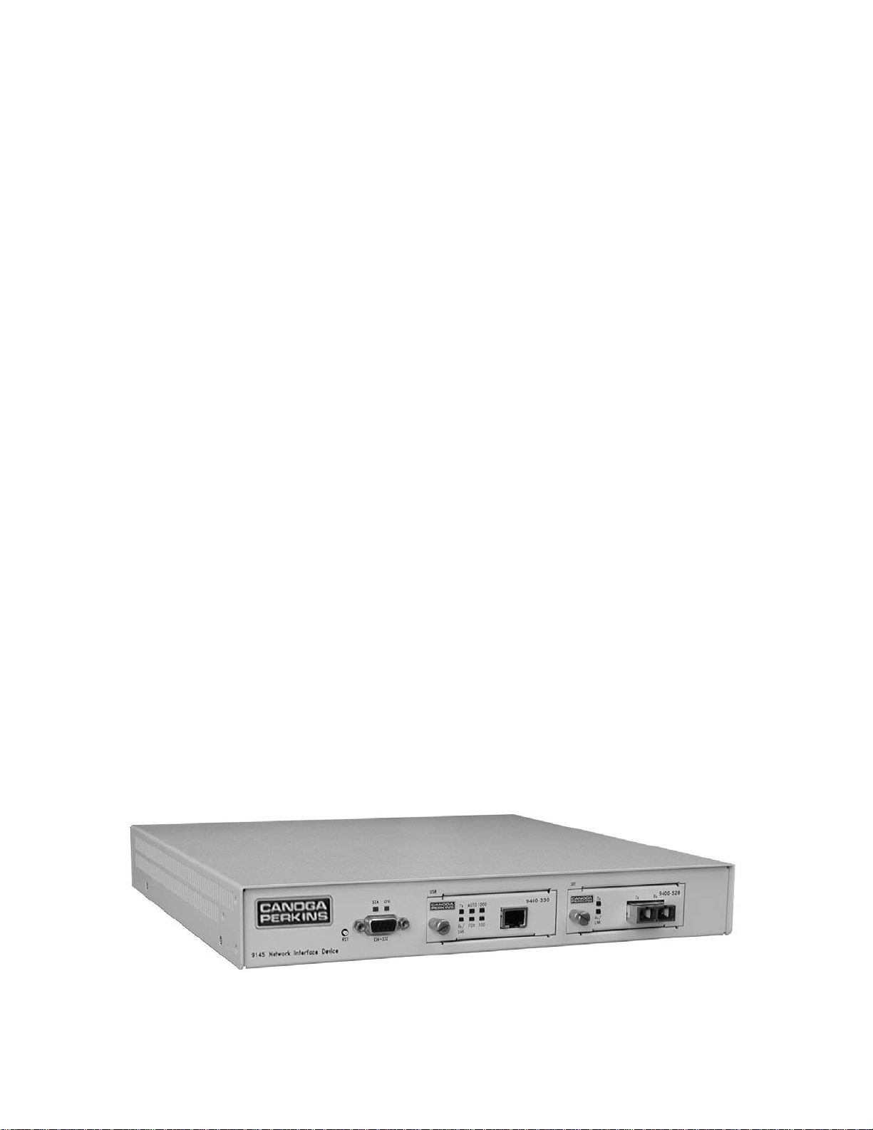
The 9145 front panel, shown in Figure 1, includes:
1. User and Extension ports; supports UTP, ST, SC and LC connectors (depending on
Interface Module Type).
2. RS-232 Serial Management Port; support VT-100 Terminal emulation and SLIP/PPP
3. Status LEDs:
• STA shows 9145 status
• CFG shows configuration and setup status
• 100, 1000, and/or FDX, depending on the type of module, show status for the
User port
• LNK/RX and TX pairs for the User and Extension ports show that data is
received and transmitted
Figure 1 – 9145
9145 Network Interface Device 1-1

Management Security
The 9145 supports enhanced security for access to Management Functions. Four network
security protocols are supported: SNMPv3, Remote Access Dial In User Security (Radius),
Secure Shell version 2 (SSH-2) and Secure File Transfer Protocol (SFTP). You can set
values and options within the software that will work with the security protocols on your
network; for specific information, see the documentation for your implementation. In
addition, the 9145 supports strong passwords, independent of the security protocol.
1. SNMPv3 provides authentication and encryption across a network.
2. The Radius server maintains user account information. At login, it authenticates the
username and password and sends a message to the 9145 to allow the login. The
Radius server can also be set up to require additional authentication information
before accepting the user. If the username or password is not valid, the Radius
server sends a message to the 9145 to disallow the login and reject the user. Set up
the parameters for the 9145 on the Radius Client Configuration screen.
3. SSH-2 provides authentication and encryption for a secure remote connection that is
similar to a standard Telnet connection, but more secure. Set up the SSH access
option individually for each User Account.
4. SFTP adds encryption to protect uploaded files during the file transfer process, such
as for a software update.
5. In software, the Security Configuration Menu provides nine options to define
password characteristics, as well as parameters that configure lockout and logout for
failed access attempts.
Optional Features
Network Performance Assurance (NPA) is a network performance measuring tool available
for the 9145. NPA actively measures network critical network parameters indicative of
overall network performance; Latency, Jitter and Frame Loss. For NPA details, please see
the Network Performance Assurance User Manual or contact your Canoga Perkins
Representative
1-2 9145 Network Interface Device
Chapter 2
Set-up and Installation
This section describes how to set up and install the 9145 and its interface modules.
Before setting up the 9145, make sure a 9 pin RS-232 cable is available (required to
connect the 9145’s Management Port to a VT100 type terminal or PC for setup and
configuration).
Installing the 9145
The 9145 is tested and inspected before shipment from the factory. If there is obvious
damage to the shipping container, contact the carrier immediately.
Caution: Follow electrostatic discharge (ESD) safety precautions when handling
Canoga Perkins products, as with all electronic devices with static
sensitive components.
1. Unpack the 9145. Keep the shipping container until the unit is installed and fully
operational. In the unlikely event that the unit is defective, contact Canoga Perkins
Customer Service for a Return Authorization Number (RMA) and instructions for return
shipment. Additional Warranty and Product Return information is in Appendix A.
2. The 9145 can be rack mounted, wall mounted, or placed on a shelf or any other flat
surface.
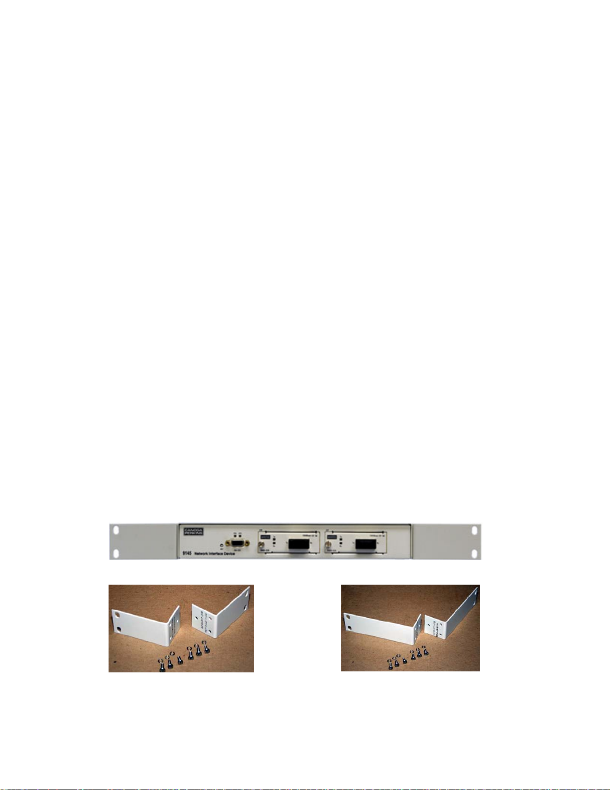
a. Rack Mounting: To rack mount the 9145, attach Rack Mount Kit 1802-2008 for
19” racks, or Rack Mount Kit 1802-2009 for 23” racks. The Rack Mount Kits
includes mounting brackets and screws to attached the brackets to the 9145..
The brackets attach to the three threaded holes on the side of the 9145 toward
the front. Be sure to place the Lock Washer between the Screw Head and
Bracket as shown figure 5.
Figure 2 – 9145 with 19” Rack Mount Brackets
Figure 3 – 19” Rack Mount Kit Figure 4 – 23” Rack Mount Kit
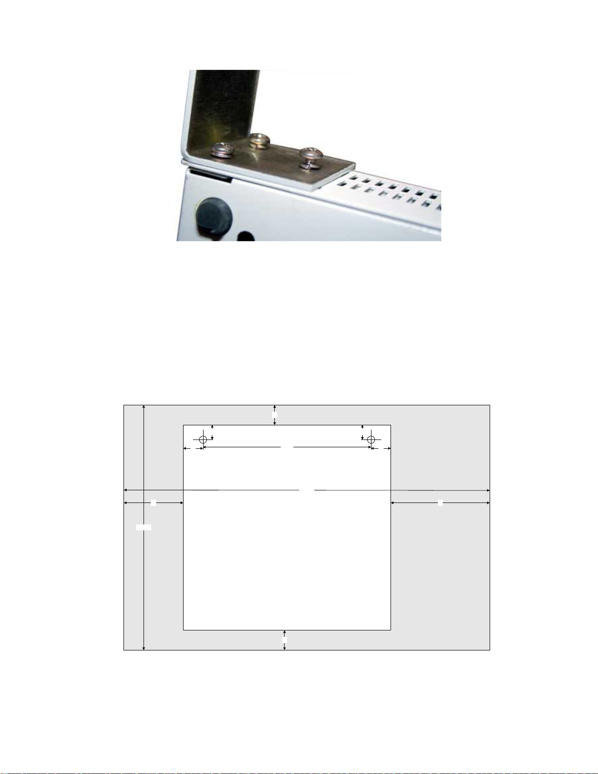
Figure 5 – Bracket Attachment Detail
b. Wall mounting: The 9145 has slotted holes on the bottom of the unit for wall
mounting. The 9145 requires 1” unobstructed space above and below the 9145
for ventilation. Canoga Perkins recommends a space of 5” on the right and 3” on
the left of 9145 bee left unobstructed to facilitate Interface Module Access, Cable
Access and Power Entry.
• Install two #10 or #12 screws and anchors in the wall 9 3/8” apart, 1” from the
sides and 3/4” from the top of the desired location of the 9145. A template is
illustrated below. Leave the screws protruding from the wall 3/8” to 3/4”.
• Hang the 9145 on the screws, matching the keyholes in the 9145 to the screws.
1"
12 3/8"
3/4"
1"
3"
9 3/8"
1
1
8
"
2
/
3/4"
1"
5"
9145
11 5/8" X 12"
1"
Figure 6 – Wall-Mount Template
9145 Network Interface Device 2-3/(2-10 Blank)
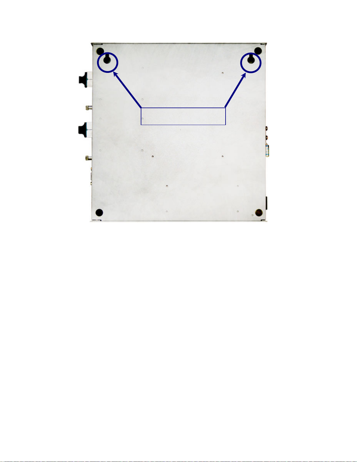
Wall Mounting Holes
Figure 7 – Bottom of 9145 showing Wall Mount Holes
c. Desktop/Shelf Placement: Place the 9145 on a secure, flat surface within reach
of the power and fiber optic cables. Leave clearance on the sides (1”), front (5”)
and rear (3”) for ventilation and to facilitate Interface Module Access, Cable
Access and Power Entry.
3. Insert Interface Modules:
a. Determine which Interface Modules are for the Extension (EXT) and User (USR)
Ports.
b. Insert a module into the appropriate slot and push firmly on the center of the front
panel. If it does not seat properly, pull the module out, inspect for bent connector
pins. If there are bent pins or other obstructions, contact Canoga Technical
Support for instructions. If all appears normal, reinsert.
c. When firmly seated, hand-tighten the screw on the Module’s front panel.
4. Connect Chassis Ground: The rear of the 9145 has a Grounding Lug for connecting the
9145 to Earth Ground. This is required for full electrical safety. Attach a 6 Gauge
copper cable between the Ground Lug and Earth Ground.
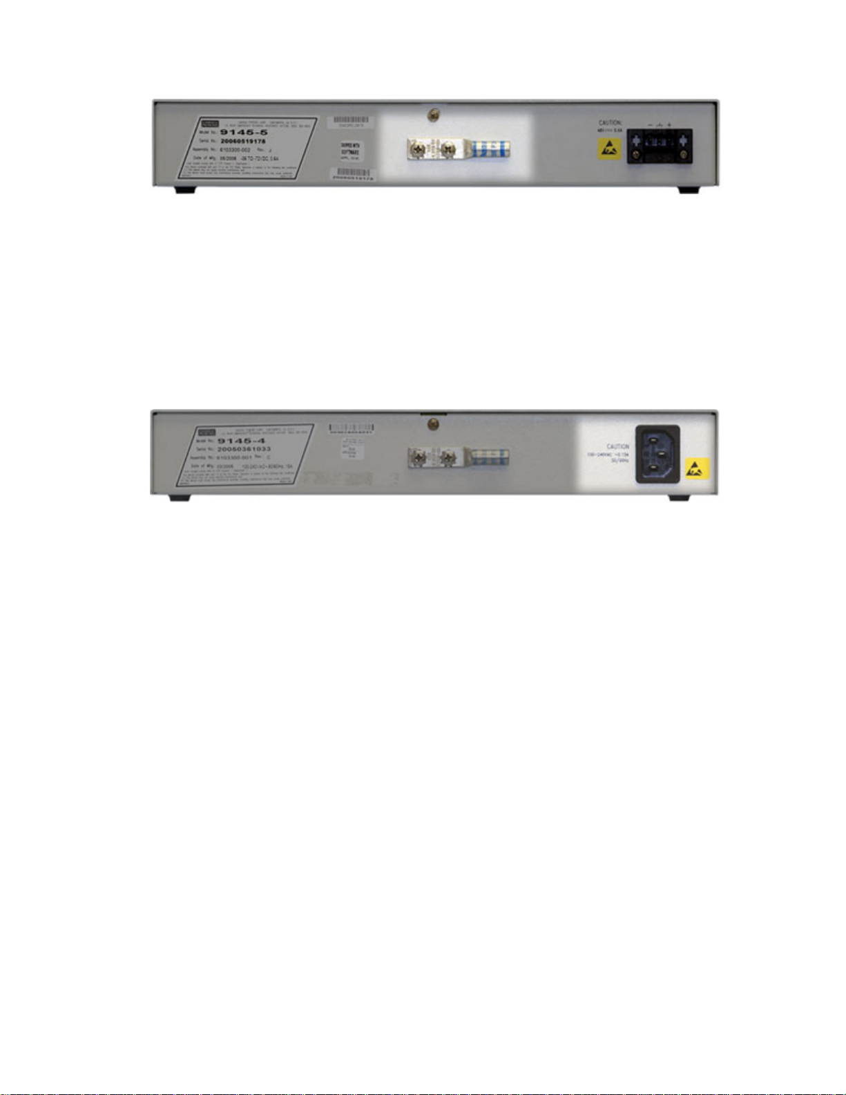
Figure 8 – Ground Lug Location
5. Connecting power. The 9145 is available with either AC or DC power.
a. Connect the AC power as follows:
• Plug the AC power cord into the socket at the rear of the 9145 and the AC
outlet.
• The 9145 is shipped with a North American Power Cord The unit uses a
standard IEC AC Power Connector. Country specific power cords are
available locally for installations outside North America.
Figure 9 – AC Power Connector Location
Caution: Reversing Power and Ground Leads can damage both the DC
source and the 9145. Damage due to reversing power is not covered
under the Warranty.
b. Connect the DC power as follows:
• The 9145 support both Positive and Negative grounded DC Power.
Loosen the screws for the GND and +48 or -48 VDC terminals
• Slide the wires under the square washers, and tighten the screws taking
care not to cross Power and Ground. The DC Power Terminal Block is
removable for ease of installation and replacement. It is recommended
the Terminal Block be removed when connecting power to avoid
accidentally crossed or shorted power leads from damaging the 9145 or
your DC Power System.
• Use an ohmmeter to verify that +/- 48 VDC Power lead is not shorted to
GND.
• Connect the power cables to the power source.
• Insert the Power Terminal Block into the 9145.
9145 Network Interface Device 2-5/(2-10 Blank)

Figure 10 – DC Power Connector Location
Caution: To avoid damaging the fiber end-surface or connector, use extreme
care when installing or removing cables.
6. Dirty optical connectors are a common cause of link loss or attenuation problems,
especially for single mode fiber (SMF). Clean the connectors before plugging in a cable
and whenever there is a significant or unexplained light loss. To prevent contamination,
always install protective dust covers on unused fiber optic connectors.
a. Wipe the ferrule and the end-face surface of the male fiber coupler with a lint-
free, isopropyl alcohol pad from a fiber cleaning kit.
b. Use canned air to blow dust out of the female fiber coupler.
7. Connecting Optical Fiber to Optical Interface Modules:
a. Plug in the optical cables with Tx (optical output) to Rx (optical input), Rx to Tx
orientation.
8. Connecting Ethernet Cables to UTP Interface Modules:
a. Plug the shielded Ethernet Cable into the UTP Connector on the Interface
Module.
b. Be sure the locking tab properly seats.
c. If the locking tab is broken or missing, replace the cable.
Caution: To maintain Lighting and Power Shorting protection, always use
Ethernet Cables with a proper Ground Shield cable and connector.
9. Canoga Perkins recommends you label the cables with the circuit number or other
identifier and the signal direction on optical cables (TX or RX).
10. Canoga Perkins recommends that you determine and record optical link attenuation
and transmission power before starting normal link traffic. The fiber optic cable optical
attenuation and Laser output power determine receive optical power level at the
receiving device. Reductions in Laser power or increases in optical loss on the fiber
optic cable can cause degraded performance and link outages. For details on link
attenuation and Laser output power, see Chapter 4.
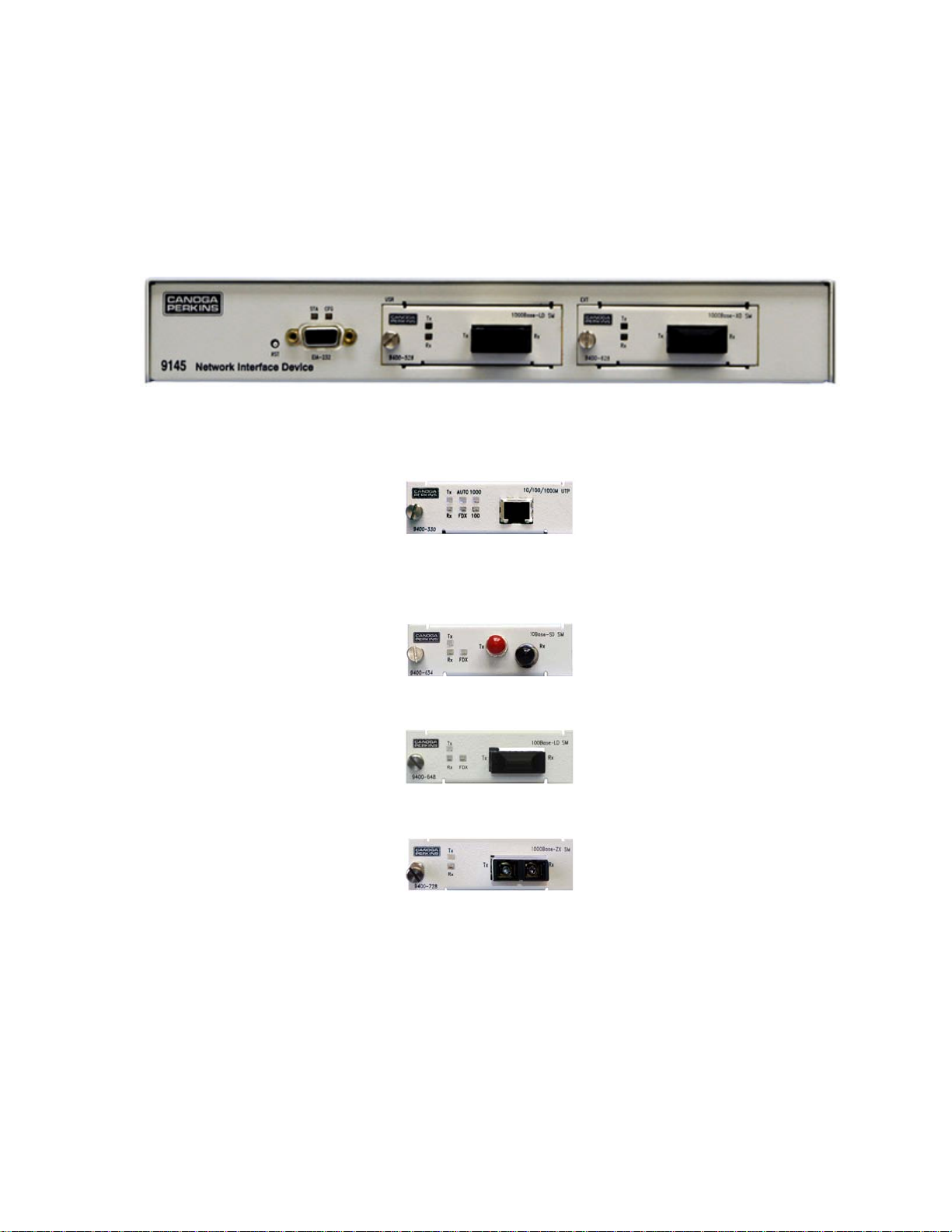
Power-Up and Front Panel Functions
The LEDs on the front panel show the system and port status. The STA and CFG LEDs
display management status. Interface Module has two, three or six LEDs, actual number is
dependant on Interface Module type.
Figure 11 – 9145 Front Panel
Figure 12 – UTP 10/100/1000 Mbps
Figure 13 – 10Mbps Optical Module
Figure 14 – 100Mbps Optical Module
Figure 15 – 1000Mbps Optical Module
During power-up, all LEDs on the 9145 and Interface Modules light amber. When start-up
has completed, the LEDs on the 9145 display status is described in Table 1. Interface
Modules display status is described in Table 2.
.
9145 Network Interface Device 2-7/(2-10 Blank)

Table 1 – 9145 Front Panel LEDs
LED Status Description
STA Off No Power
Green Normal Operation
Amber System Self-Test, Local Loopback
Amber blinking Downloading File, Remote Loopback
Red Link Down, Major alarm
CFG Off SBMC is Disabled
Green SBMC is Enabled
Amber System Self-Test
Red Configuration Error, Remote 9145 OS Different Version
Table 2 – Interface Module LEDs
LED Status Description
Rx Modules All: UTP; 10, 100, 1000 Mbps Optical
Off No activity
Green Link Established
Green blinking Receiving activity
Amber blinking Collisions
Amber System self-test
Red Remote fault
Tx Modules All: UTP; 10, 100, 1000 Mbps Optical
Off No transmission activity
Green blinking Transmission activity
Amber Port paused
Red Port disabled; may be due to LLF
FDX Modules UTP; 10, 100 Mbps Optical
Off Half duplex mode
Green Full duplex mode
100 Modules UTP Module Only
1000 100 Off, 1000 Off 10 Mbps data rate
100 Green, 1000 Off 100 Mbps data rate
100 Off, 1000 Green 1000 Mbps data rate
Remote Fault
If an optical port loses the receive optical signal, it sends a Remote Fault (RMTF)
signal on its Transmit to the distant end on the optical link. The Rx LED is off, and
an alarm flags the link loss on the optical port. When a optical port receives a
Remote Fault signal, the Rx LED lights red and an alarm flags the remote side
optical link failure. Both local and remote link partners must be configured to the
same RMTF enable/disable setting. RMTF complies with the IEEE802.3u Remote
Fault standard. See Figure 16.
• Local device Rx detects link loss
• Tx transmits RMTF to remote device
Usr
Prt
Rx
Local Device Remote Device
Ext
Prt
RxTx
Tx
RMTF
Ext
Prt
Rx
Usr
Prt
RxTx
Tx
• Local device Rx turns OFF
• Remote device Rx lights red
Figure
16 – Remote Fault Signal
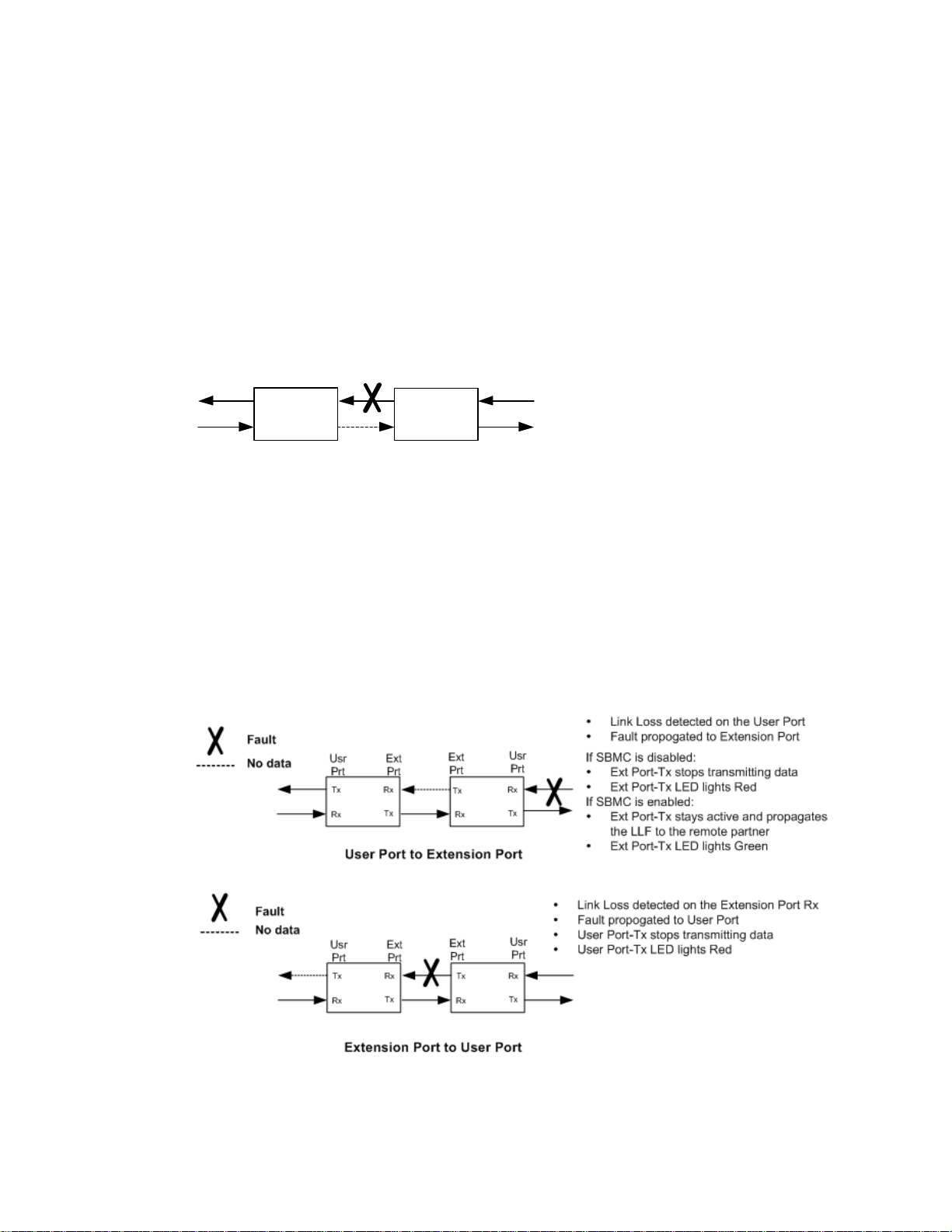
Link Loss Forwarding
When Link Loss Forwarding (LLF) is enabled, a fault on one side of the 9145
propagates to the other side to notify that device and stops signal transmission
(brings down the link). See Figure 17. Set the LLF propagation to User to
Extension, Extension to User, or both directions. Set this in the User Interface at the
Functional Configuration screen; for details, see page 3-43.
Figure 17 – Link Loss Forwarding Propagation
9145 Network Interface Device 2-9/(2-10 Blank)

Chapter 3
Management
The 9145 has three basic management interfaces, VT-100 terminal interface on the RS232 serial port and Telnet, SideBand Management Channel when connected to another
9145, a L351 Ethernet Service Unit, or a L357 Ethernet Service Unit and SNMP. Telnet
and SNMP access to the 9145 is configurable to use either the user data stream (inband) or from the RS-232 serial port when it is configured for PPP or SLIP operation.
SideBand Management Channel is a out-of-band management communication path on
the Extension port which communicates with the distant 9145, L351 or L357.
Setting Up VT-100 Terminal Network Management on the RS-232 Serial Port
When using the RS-232 Serial Port for VT-100 sessions, Canoga Perkins suggests that
you use HyperTerminal
The VT-100 Telnet Terminal Interface is only available after the management TCP/IP
configuration is complete.
The steps below briefly describe how to set up HyperTerminal on your PC. For details
on using MS Windows
1. At your MS Windows desktop, click Start, then highlight Programs, Accessories,
the HyperTerminal Folder, and then click HyperTerminal.
2. At the Connection Description dialog, select an icon, enter a name for the
connection to the system, and click OK.
3. At the Connect To dialog, pull down the Connect using menu, select the COM
port, and click OK.
4. At the COM Properties dialog, on the Port Settings tab, check for these
selections:
• Bits per second: 9600 bps
• Data bits: 8
• Parity: None
• Stop bits: 1
• Flow control: None
1
or other VT-100 Terminal Emulation program when using a PC.
2
, see your MS Windows documentation.
5. Click OK. HyperTerminal connects to the system and the VT100 terminal
emulation starts.
1 2
HyperTerminal and MS Windows are registered trademarks of Microsoft Corporation
9145 Network Interface Device 3-1

Setting Up SNMP Network Management
Typically, the 9145 communicates with CanogaView or your Network Management
Platform in-band via the transported Ethernet Network.
Network Management Platform Set-up
Industry standard Management Information Bases (MIBs) are required on your Network
Management Platform in order to successfully communication with the 9145 using
SNMP. Before you start, check that these industry-standard MIBs are loaded:
1. Standard MIB
2. Dot2sd.mib
3. Etherlike.mib
4. If.mib
5. Bridge.mib
6. Pbridge.mib
Additionally, Canoga Perkins Private MIBs are need on the Management Platform. The
Canoga Perkins Private MIBs are available on Canoga Perkins web site,
www.canoga.com
If you do not yet have a Canoga Perkins Username and Password, please contact Tech
Support.
. The MIBs are located in a password protected area of the Web Site.
1. Cp.mib: Supports all Canoga Perkins products
2. Cpsysinf.mib: Supports SNMP access
3. Cphost.mib: Supports Host Table and Host Access functions
4. Cptraptb.mib: Supports the Trap Table
9145 Set-up
There are several TCP/IP and SNMP parameters that need configuration before
accessing the 9145 from CanogaView or your Management Platform. These
parameters include TCP/IP Address, Authorized Host list and privileges. These
parameters are initially using VT-100 Terminal on the RS-232 Serial Port. Please see
the System Configuration section for details on configuring these parameters.
3-2 9145 Network Interface Device
Management User Interface
The Management User Interface for the 9145 provides screens for setup, monitoring,
and diagnostics. You can access the screens directly by connecting to the serial port of
the 9145 or using Telnet.
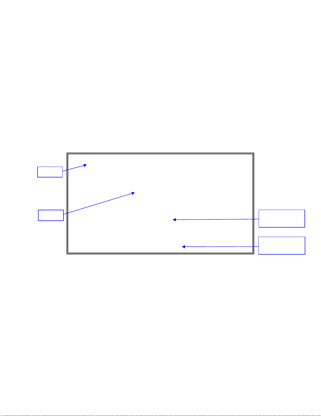
General Screen Format
A typical screen, shown in Figure 18, includes standard descriptions and reference
designations. Use this and other screens to configure the system, set operational
parameters, and verify the system status. All screens use a common method for
navigation.
Canoga Perkins Corp. Ethernet Network Interface Device 29-Nov-2006
Model 9145-5 V05.00 F96 9145 D 10:13:12
---------------------------------------MAIN MENU--------------------------------
Model
Menu
1) System Configuration
2) Diagnostics
3) Port Information
4) System Alarms
5) System Log
6) Utilities
7) Software Upgrade
8) Manage Logged In Users
9) 802.3AH OAM
10) Logout
Select [1-10]:
------------------------------------Messages------------------------------------
Navigation
Instructions
Messages and
Urgent Status
Figure 18 - General Screen Format
Not all screens and menus provide options that you can change. Some menu items
reach screens that only report status, such as revision numbers, module type, or alarms.
On other screens, you can move through and select options, and enter data.
9145 Network Interface Device 3-3

Use these keys to navigate the screens:
• Space bar When a menu item is highlighted, press <Space> to cycle through all
options for that item.
• Tab Press <Tab> to move the highlight to the next column to the right.
• Enter Press <Enter> to select the highlighted option for a menu item.
• Escape Press <Esc> once to cancel changes for the selected item or to return to
the previous screen; press <Esc> two or more times to return to the Main Menu
from two or more menu levels deep.
User Interface Organization
The user interface consists of selectable, nested screens, available in this order; this
chapter describes how to use these screens:
Main Menu
System Configuration
1.1. IP/SNMP Agent Configuration
1.1.1. Management IP Configuration
1.1.2. Auxiliary IP Configuration
Diagnostics
1.1.3. Host Table
1.1.4. Trap Table
1.2. Trap Configuration
1.3. Security Configuration
1.4. Account Configuration
1.5. System Information
1.6. Radius Client Configuration
1.7. SNTP Client Configuration
1.8. SYSLOG Client Configuration
1.9. Hardware Information
2.1. Loopback Setup
2.2. Latency/Jitter Test
2.3. PING Generation
2.4. Network Performance Assurance (Optional feature, NPA Manual)
3-4 9145 Network Interface Device

Port Information
3.1. Link Status
3.2. Port Configuration
3.3. Layer 2 Statistics
3.4. RMON Group 1 Statistics
System Alarms
System Log
Utilities
3.2.1. Hardware Information
3.2.2. Functional Configuration
3.2.3. VLAN Configuration
3.2.3.1. VLAN Rules
3.2.3.2. VLAN ID Translation Table
3.2.3.3. P-Bit Translation Tables
3.2.4. Port Filters
6.1. Set Date & Time
6.2. Reset Configuration To Default
6.3. Change Password
6.4. VT100 Baud Rate
6.5. Slip/PPP Baud Rate
6.6. PING Generation
6.7. Static ARP Table
6.8. Dynamic ARP Table
6.9. License Manager
Software Upgrade
Manage Logged in Users
802.3AH OAM
9.1. OAM Control
9.2. OAM Peer Information
9.3. OAM Statistics
9.4. OAM Event Configuration
9.5. OAM Event Log
1. Logout
9145 Network Interface Device 3-5

Login and Main Menu
The first screen is the Login Screen. Type your Username and press <ENTER>. The
Password prompt will then appear. Type your Password and press <Enter>. If the
Username or Password was incorrect, you will return to the Username Prompt.
Default Username and Password for the 9145 is admin and admin (lower case).
Canoga Perkins strongly recommends you change the Default Username and Password
during your initial configuration session.
Canoga Perkins Corp. Ethernet Network Interface Device 29-Nov-2006
Model 9145-5 V05.00 F96 9145 D 10:12:07
--------------------------------------LOGIN SCREEN------------------------------
Please Enter Login Username : admin
Please Enter Login Password : *****
------------------------------------Messages------------------------------------
The Main Menu appears after you successfully log in. It provides access to all 9145
functions including setup, diagnostics, and reports.
Canoga Perkins Corp. Ethernet Network Interface Device 29-Nov-2006
Model 9145-5 V05.00 F96 9145 D 10:13:12
---------------------------------------MAIN MENU--------------------------------
1) System Configuration
2) Diagnostics
3) Port Information
4) System Alarms
5) System Log
6) Utilities
7) Software Upgrade
8) Manage Logged In Users
9) 802.3AH OAM
10) Logout
Select [1-10]:
------------------------------------Messages------------------------------------
Figure 19 - Main Menu Selections
3-6 9145 Network Interface Device

Following is a brief description of the Main Screen Menu items
System Configuration
View and set values for the system information and communications parameters.
1. IP/SNMP Agent Configuration
The Management IP and Auxiliary IP Address are for managing and conducting
performance testing on a TCP/IP network. Enter the Management IP Address
in this field. When NPA Option is active, this screen also configures the Test IP
Address fields. Please see NPA Manual for details on Test IP Address
configuration.
2. Trap Configuration
This defines the handling of various alarm events. You can log and/or send the
event, as well as ignore it.
3. Security Configuration
This configures user and SNMP security for the 9145.
4. Account Information
This managed user access to the 9145 including privileges, passwords and
access methods.
5. System Information
This allows the addition of administrative information about the 9145 and circuit
information such as the 9145’s name, contact, location, customer, circuit,
equipment codes and CLIE information.
6. Radius Client Information
This configures the 9145 for RADIUS Authentication of user. The 9145
implements Radius Passthru for user authentication by a RADIUS Server.
7. SNTP Client Configuration
This configures the 9145 to use a primary and secondary SNTP Server for
setting date and time.
8. SYSLOG Client Configuration
This configures the 9145 to send SYSLOG messages to a SYSLOG Server for
collections and dissemination.
9. Hardware Information
This displays information about the 9145 including full model numbers of the
9145 and its Interface modules, hardware revision levels and serial numbers.
When the 9145 is connected to a remote 9145, L351 or L357 and SideBand
Management Channel is enabled, information about the remote device is also
displayed.
9145 Network Interface Device 3-7

Diagnostics
Used to set up loopback, latency and jitter, or PING tests and to configure and run
Network Performance Assurance (optional software).
Loopback Setup
This initiates and configures the 9145 for loopback diagnostics. Packets are loop
backed based on MAC address of the 9145. The 9145 is configurable to swap
origination and destination MAC addresses of the test packet and to recalculate the
CRC of the looped packet when the MAC address are swapped. Latency/Jitter Test
This manually initiated test is used to measure network latency, inter-frame jitter and
frame loss from this 9145 to a remote 9145 in a network. Configuration items are:
1. To IP Address
This is the remote 9145’s IP Address
2. From IP Address
This selects the originating IP address from the 9145 places into the test
packets. Choices are Auto Selection, Management IP or Aux IP.
3. Test VLAN
This is the VLAN Tag the test packets will carry. It can be the Management
VLAN or any customer VLAN.
4. Test Packets per sec
This lets you control the amount of packets that will be sent for every second
the test runs. Settings are: 1, 2, 5, 10, 20, 50 and 100.
5. DF Bit
This applies when you are testing with oversized packets over 1518 bytes in
length. It is an identifier in the packet that lets other network devices (i.e.
routers, switches, bridges) know if this packet can be fragmented to smaller
packets or not.
6. DSCP Precedence / Drop Probability
Short for Differentiated Services Code Point. 9145s at the edge of the
network classify packets and mark them with either the IP Precedence or
DSCP value in a Diffserv network. Other network devices in the core that
support Diffserv use the DSCP value in the IP header to select a PHB
behavior for the packet and provide the appropriate QoS treatment.
7. Test Packet Priority
This lets you set packet priority: 0 – highest priority / 7 – lowest priority.
8. Test Duration
This is the duration the test will run for in min:sec, 0 – is forever
3-8 9145 Network Interface Device

9. Min test payload (40 – 1954)
This sets the minimum test packet size in bytes. The 9145 sends test
packets ranging in size from the minimum packet size to the maximum packet
size if they are different. This is done by mapping the packets to be sent onto
the range of sizes between the minimum and maximum packet sizes. The
minimum packet size must be less than or equal to the maximum packet size.
10. Max test payload (40 – 1954)
This sets the maximum test packet size in bytes. The maximum packet size
must be greater than or equal to the minimum packet size.
11. Test Packet Timeout sec
The packet timeout for this test in seconds. If a response is not received by
the packet timeout value, the packet will be classified as dropped. The value
set here is also used to set the maximum values that can be used for both the
Latency and Jitter Measurements.
12. Start/Stop test
Starts and Stops the test.
13. Remote Latency Test
When SideBand Management Channel (SBMC) is enabled, you can initiate
and view test results of the remote unit from the local unit.
PING Generation
This is a network trouble shooting tool used to determine if a destination is reachable
from the NID. Self-Ping, pinging the Management IP Address tests connectivity
between the management processor and the 9145’s FPGA. This is an additional
self-check function.
Network Performance Assurance (Optional feature)
Accessible when the optional Network Performance Assurance (NPA) software is
installed. Please see the NPA manual for details.
9145 Network Interface Device 3-9

Port Information
The Port Information screen shows the current conditions for all ports in the 9145 with
options to view parameters and statistics for specific ports. Configuration information
includes the model number, description, and revision; the serial number; and link,
remote fault, and physical status. You must set up each port that you will use before you
can set up or assign STP, VLANs or Tagging. Below are the sub menus where these
fields reside:
Link Status
Informs you of the current link status of both user and extension ports of the NID.
Port Configuration
This screen has several sub menus. The following is a description of the menus:
1. Hardware Information
Displays 9145 hardware information, including the installed user and
extension port modules.
2. Functional Configuration
Configures and displays parameters for an individual port
3. VLAN Configuration
The VLAN Configuration screen displays and configures VLAN parameters of
the 9145.
4. Port Filters
This lets you set filters on the user and extension ports to control traffic
coming out of these specific ports depending on the packet type.
Layer 2 Statistics
Displays current Layer two Statistics
RMON Group 1 Statistics
Short for Remote Monitoring Specification (RMON). This screen displays current
RMON statistics.
System Alarms
Displays current conditions for local and remote alarms
System Log
Displays all system events
3-10 9145 Network Interface Device

Utilities
Set-up and display basic information. Below are the sub menus:
Set Date & Time
An accurate date and time in the 9145 assures accuracy for events listed in the
System Log and for traps and alarms sent to the system administrator. You can
choose either manual setting of the date and time or configure automatic updating of
the clock using SNTP. Method you use depends on the 9145’s access SNTP Server
and your need for accuracy.
Reset Configuration to Default
This allows you to set all parameters within the 9145 to be set to factory defaults.
Change Password
This option allows the current account running to change their password.
VT100 Baud Rate
This option changes the baud rate of the RS-232 Serial Port when configured for
VT100 terminal support.
Slip/PPP Baud Rate
This option changes the baud rate the RS-232 Serial Port when configured for SLIP
and PPP support
PING Generation
This is a network trouble-shooting tool used to determine if a destination is reachable
from the 9145.
Static ARP Table
The Static ARP table lets you set or change specific IP and MAC addresses
Dynamic ARP Table
The Dynamic ARP table lists currently assigned IP and MAC addresses for various
9145 ports.
License Manager
Displays additional features enabled in the 9145.
9145 Network Interface Device 3-11

Software Upgrade
Allows you to download and install new firmware, swap active firmware banks, reset
active firmware.
Manage Logged in Users
View current users logged in to the NID and allows the Administrator to force off user
sessions when needed.
802.3AH OAM
The OAM work of the 802.3ah addresses three key operational issues when deploying
Ethernet between locations: Link Monitoring, Fault Signaling and Remote Loopback.
Link Monitoring introduces some basic error definitions for Ethernet so entities can
detect failed and degraded connections.
Fault Signaling provides mechanisms for one entity to signal another that it has detected
an error.
Remote Loopback , which is often used to troubleshoot networks, allows one station to
put the other station into a state whereby all inbound traffic is immediately reflected back
onto the link. When a Remote Loopback is initiated or invoked at a Local DTE, the Local
DTE generates an event to the system log and a syslog message. Likewise, when a
Remote Loopback is exited, this also generates a system log event and a syslog
message.
OAM Configuration gives you the ability to enable or disable 802.3ah OAM mode. The
Functional Configuration screen allows parameter setting of the OAM mode on a per
port basis.
and Extension Port independently. You can configure each port to 802.3ah Active
Mode, 802.3ah Passive Mode, or Disable 802.3ah OAM.
When 802.3ah OAM Mode is disabled, the 9145 is transparent to 802.3ah OAMPDUs.
All incoming OAMPDUs will pass through the 9145 transparently and the 9145 does not
generate any OAMPDUs (effectively, the OAM Sublayer will be bypassed and all frames
will be forwarded to the superior sublayer).
When a Remote Loopbacks are initiated or invoked from Local 9145, it generates an
event to the system log and generates an equivalent Syslog Message. Likewise, when a
Remote Loopback is exited, the 9145 generates an event to the system log and an
equivalent Syslog message.
There are three types of Events: Critical Events, Link Fault Events and Dying Gasp
Events. The specific faults that comprise these events are defined as follows:
1. A Critical Event occurs when a software reset is invoked. A hard reset does not
2. A Link Fault Event occurs when the local PHY receiver detects a LOC
3. A Dying Gasp Event occurs when a power supply failure has occurred.
This allows you the ability to set the 802.3ah OAM mode for the User Port
generate a Critical Event since it resets the processor as soon as it is asserted.
condition.
3-12 9145 Network Interface Device
 Loading...