

CANOGA PERKINS 9140 User Manual

Model 9135 Two-Port
and 9140 Four-Port
SNMP Managed Fast
Ethernet Switch
User Manual
Deleted:
Deleted: and
Deleted: 
Canoga Perkins


EdgeAccess SNMP Managed Fast Ethernet Switch
CAUTION!
This product may contain a laser diode emitter operating at a wavelength of 1300nm - 1600nm. Use of
optical instruments (for example: collimating optics) with this product may increase eye hazard. Use of
controls or adjustments or performing procedures other than those specified herein may result in hazardous
radiation exposure.
Under normal conditions, the radiation levels emitted by this product are under the Class 1 limits in 21 CFR
Chapter 1, Subchapter J.
ATTENTION!
Cet équipement peut avoir une diode laser émettant à des longueurs d'onde allant de 1300nm à 1600nm.
L'utilisation d'instruments optiques (par exemple : un collimateur optique) avec cet équipement peut
s'avèrer dangereuse pour les yeux. Procéder à des contrôles, des ajustements ou toute procédure autre que
celles décrites ci-après peut provoquer une exposition dangereuse à des radiations.
Sous des conditions normales, le niveau des radiations émises par cet équipement est en dessous des limites
prescrites dans CFR21, chapitre 1, sous chapitre J.
NOTICE!
This device contains static sensitive components. It should be handled only with proper Electrostatic
Discharge (ESD) grounding procedures.
NOTE!
Cet équipement contient des composants sensibles aux décharges électro-statiques. Il doit absolument être
manipulé en respectant les règles de mise à la terre afin de prévenir de telles décharges.
Model 9135/9140
Deleted: Page of 871
i

NOTICE
Canoga Perkins has prepared this user manual for use by customers and Canoga Perkins personnel as a
guide for the proper installation, operation and/or maintenance of Canoga Perkins equipment. The
drawings, specifications and information contained in this document are the property of Canoga Perkins
and any unauthorized use or disclosure of such drawings, specifications and information is prohibited.
Canoga Perkins reserves the right to change or update the contents of this manual and to change the
specifications of its products at any time without prior notification. Every effort has been made to keep the
information in this document current and accurate as of the date of publication or revision. However, no
guarantee is given or implied that the document is error free or that it is accurate with regard to any
specification.
CANOGA PERKINS CORPORATION
20600 Prairie Street
Chatsworth, California 91311-6008
Business Phone: (818) 718-6300
(Monday through Friday 7 a.m. - 5 p.m. Pacific Time)
FAX: (818) 718-6312 (24 hrs.)
Web Site: www.canoga.com
Email: fiber@canoga.com
Copyright © 1999 - 2005 Canoga Perkins Corporation
All Rights Reserved
Universal Chassis System
9135 Two-Port and 9140 Four-Port
SNMP Managed Fast Ethernet Switch
Model Number 9135 / 9140 - UM
Part Number 6912040
To reference Technical Advisories and Product Release Notes, go to Canoga Perkins' website:
http://www.canoga.com
EdgeAccess®
User Manual
Rev. K
09/2005
ii

EdgeAccess SNMP Managed Fast Ethernet Switch
Table of Contents
Chapter 1 Quick Start Installation.......................................................................................................... 1-2
1.1 Typical EdgeAccess 9135 Two-Port Switch Application............................................................ 1-2
1.2 EdgeAccess 9135/9140 Redundant Switch Application.............................................................. 1-3
1.
3 Quick Start Installation of the 9135/9140 Switch........................................................................ 1-4
4 Quick Start Interface DIP Switch Settings .................................................................................. 1-5
1.
5 Quick Start Configuration of the 9100-300 10/100BASE-TX UTP Interface............................. 1-6
1.
1.
6 Quick Start Configuration of the 9100-310 10/100BASE-TX UTP Interface............................. 1-7
7 Quick Start Configuration of the 10BASE-FL/100BASE-FX Interfaces.................................... 1-8
1.
8 Quick Start Interface Connection ................................................................................................ 1-9
1.
1.
9 Quick Start Management Module Cable Attachment ................................................................ 1-10
10 Quick Start PC Configuration for Terminal Operation.............................................................. 1-11
1.
C
hapter 2 Overview .................................................................................................................................. 2-1
2.
1 EdgeAccess 9135 Two-Port and 9140 Four-Port Fast Ethernet Switch ...................................... 2-1
2.
2 Main Features .............................................................................................................................. 2-2
C
hapter 3 Installation and Setup.............................................................................................................3-1
3.1 Installation................................................................................................................................... 3-1
3.1.1 Unpacking.................................................................................................................................... 3-1
3.
1.2 Rack Mount Installation .............................................................................................................. 3-1
1.3 Wall Mount Installation............................................................................................................... 3-2
3.
1.4 Stand Alone Installation .............................................................................................................. 3-2
3.
3.
2 Setup............................................................................................................................................ 3-3
2.1 9100-300 10/100BASE-TX Module............................................................................................ 3-4
3.
2.2 9100-310 10/100BASE-TX Module............................................................................................ 3-5
3.
3.
2.3 100BASE-FX Single Mode Module............................................................................................ 3-6
2.4 100BASE-FX Multimode Module .............................................................................................. 3-7
3.
2.5 10BASE FL Single Mode Module .............................................................................................. 3-8
3.
3.
2.6 10BASE-FL Multimode Module............................................................................................... 3-10
2.7 10BASE-5 AUI Module ............................................................................................................ 3-11
3.
2.8 Relay Contacts........................................................................................................................... 3-12
3.
3.
2.9 AC/DC Power and Switch......................................................................................................... 3-13
3.2.9.1 AC Power Entry and Switch ............................................................................................................3-13
3.2.9.2 DC Power Entry ...............................................................................................................................3-13
Chapter 4 Software Management............................................................................................................4-1
4.1 SNMP Management Overview - VT100 ..................................................................................... 4-1
4.1.1 Management Access - Terminal.................................................................................................. 4-1
1.2 Management Access - Telnet....................................................................................................... 4-1
4.
4.
1.3 Management Access - Modem SLIP Connection........................................................................ 4-1
1.4 Front Panel Diagnostics............................................................................................................... 4-2
4.
2 BOOT Loader.............................................................................................................................. 4-2
4.
4.
3 Configuration Manager................................................................................................................ 4-2
4 Bridging / Spanning Tree ............................................................................................................ 4-2
4.
5 TCP/IP Stack ............................................................................................................................... 4-3
4.
4.
6 SNMP Management Agent.......................................................................................................... 4-3
7 RMON Probe............................................................................................................................... 4-3
4.
8 BOOTP........................................................................................................................................ 4-4
4.
C
hapter 5 Management Setup and Operation........................................................................................5-1
5.1 Setup and Configuration of the Serial Port.................................................................................. 5-1
5.1.1 PC Configuration for Terminal Operation................................................................................... 5-1
Deleted: 
Formatted
Formatted
Formatted
Formatted
Formatted
Formatted
Deleted: Page of 871
Model 9135/9140
iii

5.2 Operation of the VT100 Program................................................................................................ 5-4
2.1 System Menu............................................................................................................................... 5-5
5.
5.2.1.1 IP Settings...........................................................................................................................................5-6
5.2.1.2 Host Table / SNMP Settings ..............................................................................................................5-7
5
.2.1.3 SLIP Port Settings ..............................................................................................................................5-8
.2.1.4 Passwords ...........................................................................................................................................5-9
5
5
.2.1.5 Network Name..................................................................................................................................5-12
5
.2.1.6 Redundancy Setting..........................................................................................................................5-12
5
.2.1.7 Redundancy (Backup) Mode............................................................................................................5-13
5
.2.1.8 Redundant Mode - SNMP Traps...................................................................................................... 5-14
5.2.2 Switch Configuration................................................................................................................. 5-15
5.2.2.1 Spanning Tree...................................................................................................................................5-15
5.2.2.2 Global Spanning Tree.......................................................................................................................5-17
.2.2.3 Port Parameters................................................................................................................................. 5-18
5
5
.2.2.4 Configurable Port options ................................................................................................................5-18
5
.2.2.5 Spanning Tree Reports .....................................................................................................................5-19
5
.2.2.6 VLAN Configuration ....................................................................................................................... 5-20
5.2.3 Port Information ........................................................................................................................ 5-22
5.2.4 Reports....................................................................................................................................... 5-23
5.2.4.1 Description Screen ...........................................................................................................................5-23
5.2.4.2 Traps Log Screen.............................................................................................................................. 5-24
5.2.5 Diagnostics ................................................................................................................................ 5-25
5.2.5.1 Ping ................................................................................................................................................... 5-25
5.2.5.2 Sniffer Settings (9140 Four-Port Switch) ........................................................................................5-26
5.2.6 Restore Defaults ........................................................................................................................ 5-26
5.2.7 Restart Unit................................................................................................................................ 5-26
5.
2.8 Logout ....................................................................................................................................... 5-26
5.3
5.4
C
6.
6.
6.
6.
6.
6.
6.
6.
A
Update the 9135 or 9140 Software Through TFTP ................................................................... 5-27
Update the 9135 or 9140 Software Through FTP...................................................................... 5-28
hapter 6 Specifications...........................................................................................................................6-1
1 Interfaces ..................................................................................................................................... 6-1
2 Switching Characteristics ............................................................................................................ 6-3
2.1 Management Board – Characteristics.......................................................................................... 6-3
3 Indicators..................................................................................................................................... 6-4
4 Alarms ......................................................................................................................................... 6-4
5 Physical / Environmental............................................................................................................. 6-5
6 Regulatory Compliance ............................................................................................................... 6-5
7 Referenced Documents................................................................................................................ 6-5
ppendix A Default Values..................................................................................................................... A-1
Appendix B SLIP Instructions................................................................................................................ B-1
B.1 EdgeAccess Application with SNMP via SLIP .......................................................................... B-1
B.2 Configuring the 9135 or 9140 for SLIP...................................................................................... B-2
B.3 Setting up a Serial Line IP (SLIP) Connection with Windows NT ............................................ B-3
Appendix C Acronyms / Abbreviations.................................................................................................. C-1
Appendix D Limited Warranty............................................................................................................... D-1
Formatted
Formatted
Formatted
Formatted
Formatted
Formatted
Formatted
Formatted
Formatted
iv
EdgeAccess SNMP Managed Fast Ethernet Switch
List of Figures
Figure 1-1. Typical 9135 10/100Mbps UTP/Fiber Application.................................................................. 1-2
igure 1-2. Typical 9140 10/100Mbps UTP/Fiber Application.................................................................. 1-3
F
igure 1-3. Power Entry Module and Switch. ............................................................................................ 1-4
F
F
igure 1-4. 9135/9140 UTP and Fiber Interfaces and Connectors. ............................................................ 1-5
igure 1-5. DIP Switch Location - UTP Interface...................................................................................... 1-7
F
igure 1-6. 9100 Series SMF Interface....................................................................................................... 1-8
F
F
igure 1-7. 9135 or 9140 UTP and SMF Interface Connectors and LEDs................................................. 1-9
Figure 1-8. SNMP Management Module. ................................................................................................ 1-10
Figure 1-9. Naming the HyperTerminal File............................................................................................ 1-11
Figure 1-10. COM Port Selection Screen. ................................................................................................ 1-12
Figure 1-11. COM1 Properties Screen. .................................................................................................... 1-12
F
igure 1-12. Opening Screens for the 9135/9140 SW File....................................................................... 1-13
igure 2-1. 9135 Two-Port and 9140 Four-Port Fast Ethernet Switch (Front Panel)................................. 2-1
F
igure 3-1. Installing Rack Mount Ears...................................................................................................... 3-1
F
F
igure 3-2. Wall mount Installation............................................................................................................ 3-2
igure 3-3. Fan Assembly and Power Entry Socket................................................................................... 3-2
F
igure 3-4. Front View of the 9135 Two-Port Switch and 9140 Four-Port Switch.................................... 3-3
F
F
igure 3-5. 10/100BASE TX Interface Module. ........................................................................................ 3-4
igure 3-6. 100BASE FX Single Mode Module. ....................................................................................... 3-6
F
Figure 3-7. 100BASE FX Multimode Module. .......................................................................................... 3-7
Figure 3-8. 10BASE-FL Single Mode Module........................................................................................... 3-8
Figure 3-9. 10BASE-FL Multimode Module. .......................................................................................... 3-10
Figure 3-10. 10BASE-5 AUI DTE Module.............................................................................................. 3-11
Figure 3-11. 10BASE-5 AUI DCE Module.............................................................................................. 3-11
Figure 3-12. Relay Contacts on Rear Panel.............................................................................................. 3-12
Figure 3-13. Power Entry Module with AC Power Switch. ..................................................................... 3-13
Figure 3-14. Typical DC Power Supply Connections............................................................................... 3-14
igure 4-1. VT100 Management Connection - Terminal. .......................................................................... 4-1
F
Figure 4-2. Telnet Management Connection - Terminal. ........................................................................... 4-1
Figure 4-3. Modem SLIP Management Connection - SLIP. ...................................................................... 4-1
igure 4-4. SNMP Management Diagnostic LEDs. ................................................................................... 4-2
F
F
igure 5-1. SNMP Management Module. .................................................................................................. 5-1
igure 5-2. Naming the HyperTerminal Connection File........................................................................... 5-2
F
igure 5-3. COM Port Selection Screen. .................................................................................................... 5-2
F
F
igure 5-4. COM1 Properties Screen. ........................................................................................................ 5-3
igure 5-5. The 9135/9140 Switch Main Menu.......................................................................................... 5-3
F
Figure 5-6. Opening Screens for the 9135 or 9140 SW File....................................................................... 5-4
Figure 5-7. System Menu. .......................................................................................................................... 5-5
Figure 5-8. IP Settings Menu...................................................................................................................... 5-6
Figure 5-9. Host Table and SNMP Settings Menu. .................................................................................... 5-7
F
igure 5-10. Highlighted Field to be Configured / Changed...................................................................... 5-8
igure 5-11. SLIP Port Settings Menu........................................................................................................ 5-8
F
igure 5-12. SLIP Port Setup...................................................................................................................... 5-9
F
F
igure 5-13. Passwords Menu. ................................................................................................................. 5-10
igure 5-14. Name a Network. ................................................................................................................. 5-12
F
Figure 5-15. Redundancy Setting Screen. ................................................................................................ 5-13
Figure 5-16. Redundancy Port Information.............................................................................................. 5-13
igure 5-17. Port 2 Failure Screen............................................................................................................ 5-14
F
igure 5-18. Switch Configuration Menu................................................................................................. 5-15
F
F
igure 5-19. Graphical Depiction of a Spanning Tree Application.......................................................... 5-16
igure 5-20. Spanning Tree Parameters. .................................................................................................. 5-17
F
F
igure 5-21. Global Spanning Tree Parameters Menu. ............................................................................ 5-18
igure 5-22. Port Spanning Tree Parameters............................................................................................ 5-19
F
Formatted
Formatted
Formatted
Formatted
Formatted
Formatted
Formatted
Formatted
Formatted
Formatted
Formatted
Formatted
Formatted
Formatted
Formatted
Formatted
Formatted
Formatted
Deleted: Page of 871
Model 9135/9140
v

Figure 5-23. Spanning Tree Report Screen. ............................................................................................. 5-20
igure 5-24. Switch to VLAN Configuration........................................................................................... 5-20
F
igure 5-25. VLAN Configuration Screen. .............................................................................................. 5-21
F
F
igure 5-26. VLAN Configuration for Assigning VLAN Ports. .............................................................. 5-21
igure 5-27. Port Information Screen....................................................................................................... 5-22
F
igure 5-28. Single Port and All Ports Statistics Screen........................................................................... 5-22
F
F
igure 5-29. Reports Menu....................................................................................................................... 5-23
igure 5-30. Description Screen. .............................................................................................................. 5-23
F
igure 5-31. Traps Log Screen................................................................................................................. 5-24
F
F
igure 5-32. Diagnostics Menu. ............................................................................................................... 5-25
igure 5-33. Ping Screens......................................................................................................................... 5-25
F
Figure 5-34. Sniffer Settings..................................................................................................................... 5-26
Figure 5-35. Restore Defaults, Restart Unit and Logout from Main Menu. ............................................. 5-27
igure 5-36. Software Revision Check..................................................................................................... 5-28
F
F
igure 6-1. Male/Female Cable Connector Pins......................................................................................... 6-2
igure B-1. 9140 in Redundant Optics Mode with SLIP........................................................................... B-1
F
igure B-2. Main Menu Screen. ................................................................................................................ B-2
F
F
igure B-3. SLIP Port Settings.................................................................................................................. B-2
igure B-4. Windows NT Control Panel with Modem Icon Selected. ...................................................... B-3
F
igure B-4a. Modem Properties................................................................................................................ B-4
F
F
igure B-4b. Modem Speed Properties. .................................................................................................... B-4
Figure B-5. General Modem Dialing Properties........................................................................................ B-5
Figure B-6. Dial-Up Networking............................................................................................................... B-5
Figure B-7. Dial-Up Networking Screen................................................................................................... B-6
Figure B-9. Server Setup. .......................................................................................................................... B-7
igure B-10. SLIP TCP/IP Settings........................................................................................................... B-7
F
F
igure B-11. Script Settings. ..................................................................................................................... B-8
Figure B-12. Initialize Dial-Up to Remote 9135 or 9140. ......................................................................... B-8
Figure B-13. Confirm SLIP Connection.................................................................................................... B-9
F
igure B-14. Initiating Telnet Session via MSDOS. ................................................................................. B-9
igure B-15. Connecting Telnet Session via MSDOS..............................................................................B-10
F
Formatted
Formatted
Formatted
Formatted
Formatted
List of Tables
Table 1-1 Interface Default Settings ………………………………………………………………… 1-5
vi

EdgeAccess SNMP Managed Fast Ethernet Switch
Canoga Perkins EdgeAccess
SNMP Managed Fast Ethernet Switch
Model 9135 Two-Port Switch and Model 9140 Four-Port Switch
Model 9135/9140
Deleted: Page of 871
vii

This page intentionally left blank.
viii

EdgeAccess SNMP Managed Fast Ethernet Switch
Deleted: 
Formatted
Deleted: Page of 871
Model 9135/9140
1-1
Chapter 1
Quick Start Installation
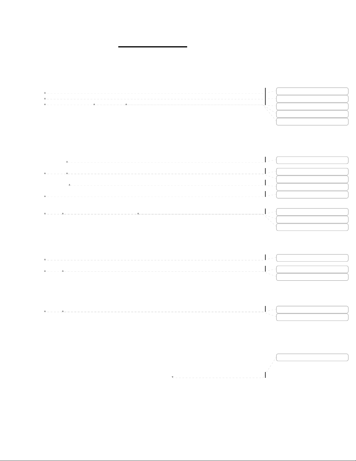
1.1 Typical EdgeAccess 9135 Two-Port Switch Application
The application shown in Figure 1-1 represents a carrier style circuit that provides 10Mbps and 100Mbps
Transparent LAN Service (TLS) between multiple customer or user locations. The design uses NEBS Level
3 compliant 9119 and 8829 media converters at the central location, and SNMP managed 9135 or 9140
Fast Ethernet Fiber Optic switches at the edge of the network. This example shows the 10Mbps 8829 and
100Mbps 9119 attaching to 10/100BASE-TX switch based UTP interfaces and converting the signals from
copper to single mode optical signals. The signal is in turn connected to the 9135 at the edge of the network
where the 9135 terminates the single mode fiber from the central site and offers UTP, or multimode optical
interfaces for connection to the user equipment.
The 9135 and 9140 switches along with the 8829 media converter feature interoperable 10BASE-T UTP
and 10BASE-FL 850nm multimode, 1310nm and 1550nm single mode optical interfaces. At 100Mbps, the
9135 and 9140 switches and 9119 media converter support 100BASE-TX/FX UTP and 1310nm
multimode, 1310nm and 1550nm single mode optical interfaces, all with a choice of optical loss budgets
and connectors.
Formatted
1-2
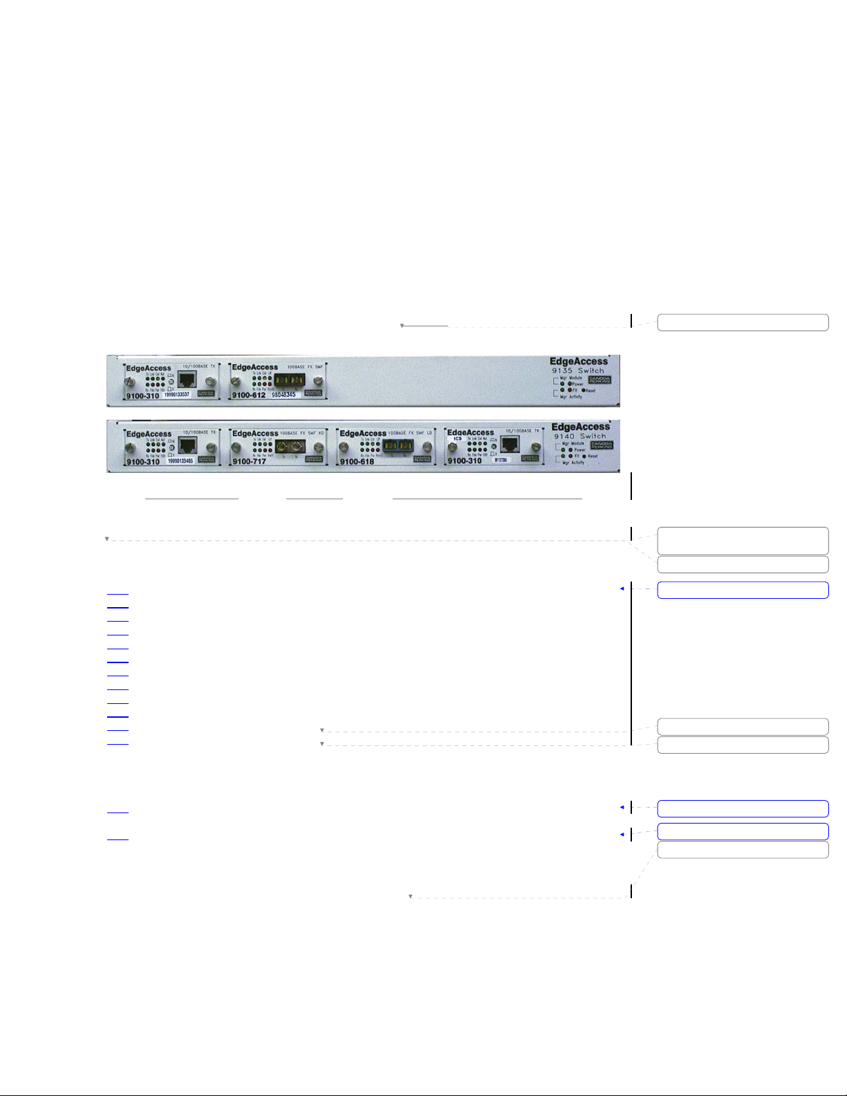
Figure 1-1. Typical 9135 10/100Mbps UTP/Fiber Application.
EdgeAccess SNMP Managed Fast Ethernet Switch
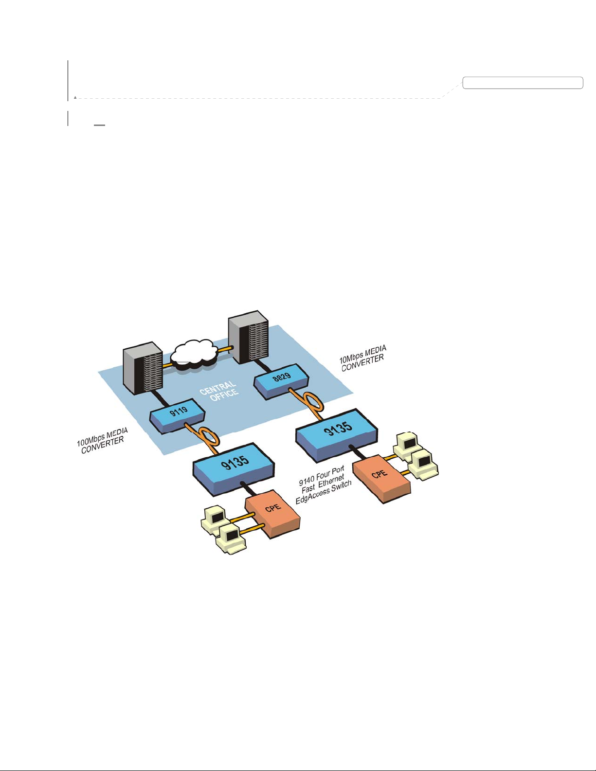
1.2 EdgeAccess 9135/9140 Redundant Switch
Application
The application shown in figure 1-2 represents a carrier style circuit that provides 100Mbps Transparent
LAN Service (TLS) and fiber optic path redundancy between customer or user locations. The design uses a
NEBS Level 3 compliant 9119 media converter and 9140 Four-Port switch at the central location, and
SNMP managed 9140 Fast Ethernet Fiber Optic switches at the edge of the network. This example shows a
centrally located 9119 and 9140 attached to 10/100BASE-TX switch based UTP interfaces and converting
from the received copper signal to the single mode optical waveform. The optical interfaces are in turn
connected to the 9140 at the edge of the network where they terminate the single mode fiber from the
central site and offer UTP or multimode optical interface for connection to the user equipment.
In the circuit with fiber path redundancy, the central 9140 has two 100BASE-FX single mode optical
interfaces configured as a redundant pair, which are then connected by divergent optical paths to the 9140s
at the customer premise. If a loss of light is detected at the receiver due to a fiber cut, the units will switch
to the fallback or redundant pair almost instantaneously.
Figure 1-2. Typical 9140 10/100Mbps UTP/Fiber Application.
Model 9135/9140
Deleted: Page of 871
1-3
1.3 Quick Start Installation of the 9135/9140 Switch
The initial setup of your EdgeAccess 9135 Two-Port or 9140 Four-Port Switch (9135/9140) involves four
stages:
•
Selecting the location for the 9135 or 9140 Switch
• Configuring the interface modules
• Connections for a selected application
• Management connection and operation
Step 1 Unpack the Switch and determine the best method of installation for your unit; stand alone, rack
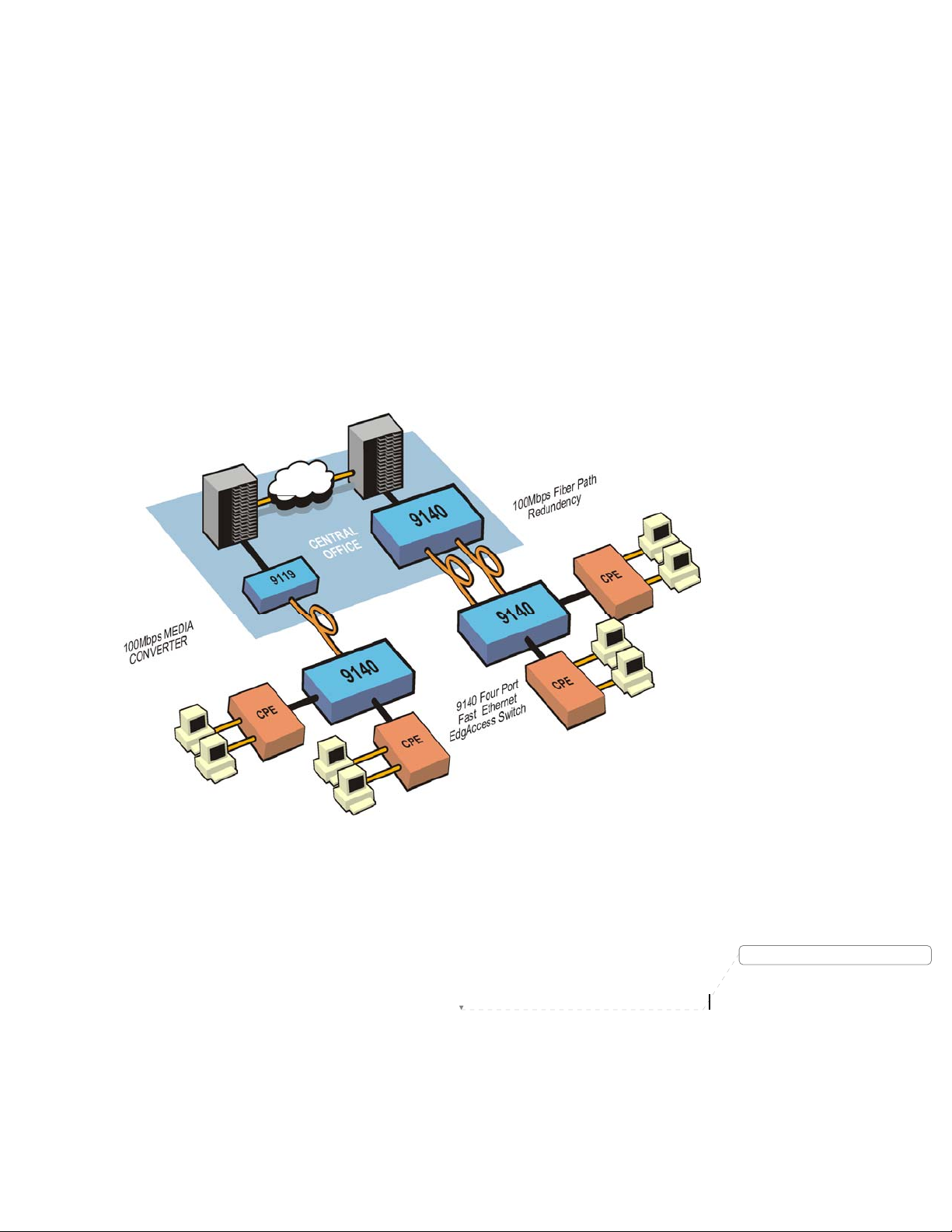
Step 2 With the 9135 or 9140 securely in place, plug the supplied power cord, female end, into the power
mount, or wall mount. Refer to chapter 4 for detailed unpacking instructions and mounting
considerations.
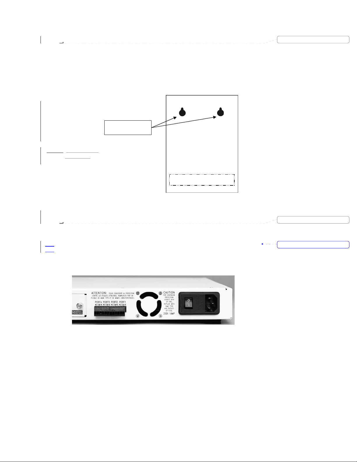
entry module on the rear of the unit (see Figure 1-3). Plug the male end of the cord into an AC
outlet. Turn on the power switch located on the power entry module.
Power Entry Module with
AC Power Switch
Deleted: 1.3
Formatted: Bullets and Numbering
1-4
Figure 1-3. Power Entry Module and Switch.
EdgeAccess SNMP Managed Fast Ethernet Switch
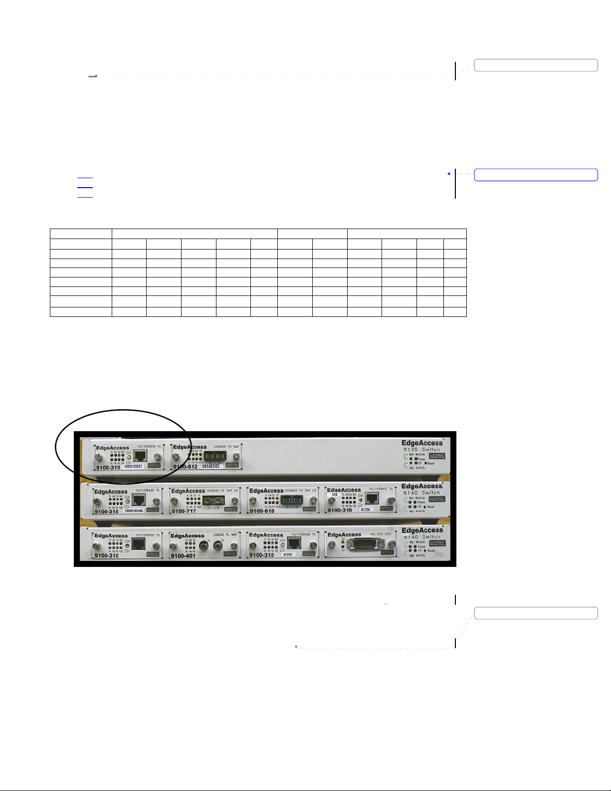
1.4 Quick Start Interface DIP Switch Settings
Deleted: 3
Although the 10/100BASE-TX UTP interface is factory configured for auto negotiation, it is recommended
that the configuration of each individual interface be confirmed prior to the connection of the 9135 TwoPort Switch or 9140 Four-Port Switch to any equipment. The fixed speed 10BASE-FL and 100BASE-FX
fiber interfaces are configured for full-duplex operation (reference Table 1-1 for factory default settings).
The 10/100BASE-TX UTP interface (see Figure 1-4) can be configured manually or set for auto
negotiation mode. The various modes of operation include:
Auto Negotiation
•
Formatted: Bullets and Numbering
• 10Mbps Half-duplex and Full-duplex
• 100Mbps Half-duplex and Full-duplex
Table 1-1. Interface Default Settings.
UTP 100 FX 10 FL
SW Position
100BASE ON
FULL-DUPLEX ON ON ON
AUT ON
LL ENABLE ON ON
LOW POW ON
CROSS OVER X
SQUELCH JP X *
SW1-1 SW1-2 SW1-3 SW1-4 SW2 SW1-1 SW1-2 SW2-1 SW2-2 SW1 W1
X = cross over switch is in the X position
X * = jumper is not installed
Note: Since the 9140 is a Four-Port device and LLF is designed to operate with two ports, interfaces
inserted into the 9140 with LLF enabled will function normally but will have LLF disabled.
Figure 1-4. 9135/9140 UTP and Fiber Interfaces and Connectors.
Model 9135/9140
Deleted: Page of 871
1-5

1.5 Quick Start Configuration of the 9100-300
10/100BASE-TX UTP Interface
Configure the UTP interface as follows:
Step 1 Insert the UTP interface into the 9135 Two-Port Switch or 9140 Four-Port Switch, and tighten the
Step 2 Set the 9100-300 to 10 BASE -TX or 100 BASE-TX in software. For details, see Chapter 5.
Note: Although the 9135 and 9140 is designed to soft reset whenever a card is inserted, it may not always
do so; therefore after inserting a card, monitor the unit for a reset. If the unit fails to do so, force a reset
manually by depressing the reset button on the right side of the unit.
captive screws down. When the correct UTP and fiber cable attachments are completed, the
Interface LEDs will provide indications that confirm the dip switch settings. Refer to Section 1.8,
"Quick Start Interface Connection," for detailed information on the LED indicators.
1-6
EdgeAccess SNMP Managed Fast Ethernet Switch
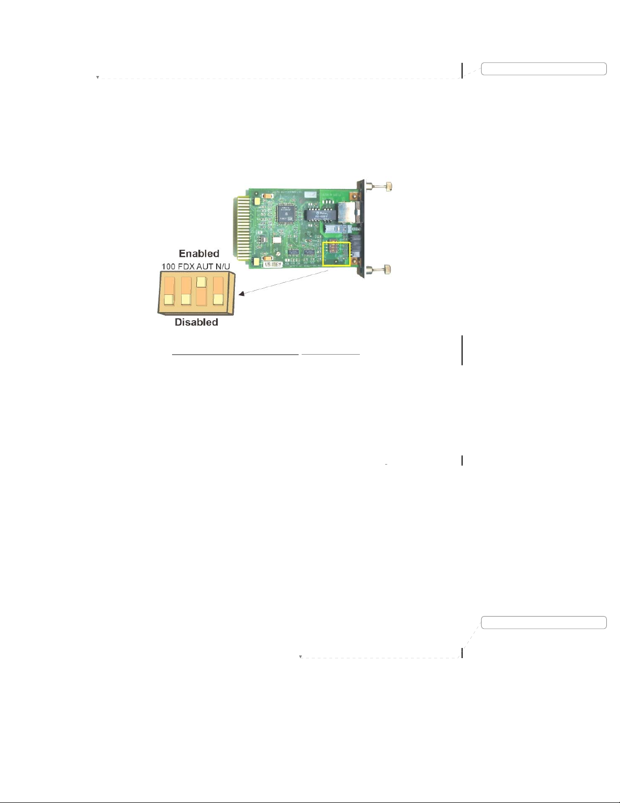
1.6 Quick Start Configuration of the 9100-310
10/100BASE-TX UTP Interface
Configure the UTP interface as follows:
Step 1 Remove the UTP interface from the 9135 Two-Port Switch or the 9140 Four-Port Switch by
DIP 1 100Mbps When set to the on, or enabled position, the interface will be configured for
100Mbps; in the disabled or off position, the interface will be set for 10Mbps.
DIP 2 FDX When set to the on, or enabled position, the interface will be configured for
full-duplex operation; otherwise, the interface will be set for half-duplex
DIP 3 AUT When set to the on, or enabled position, the UTP interface will auto negotiate for
Note: DIP Switch 3, AUT, overrides DIP Switch 2 FDX/HDX and DIP Switch 1, 10/100Mbps.
DIP 4 Not Used This switch is not used and does not effect normal operation.
Step 2 Insert the UTP interface back into the 9135 Two-Port Switch or 9140 Four-Port Switch, and
Note: Although the 9135 and 9140 is designed to soft reset whenever a card is inserted, it may not always
do so; therefore after inserting a card, monitor the unit for a reset. If the unit fails to do so, force a reset
manually by depressing the reset button on the right side of the unit.
unscrewing the front panel captive screws and pulling the interface out of the unit. Locate the
four-position DIP switch as shown in Figure 1-5, and set the switches to the appropriate settings
for your specific application using a nonconductive stylus.
Figure 1-5. DIP Switch Location - UTP Interface.
operation.
the highest available speed and duplex operation between the,
Switch or 9140 Four-Port Switch, and the attached UTP port.
tighten the captive screws down. When the correct UTP and fiber cable attachments are
completed, the Interface LEDs will provide indications that confirm the dip switch settings. Refer
to Section 1.8, "Quick Start Interface Connection," for detailed information on the LED indicators.
9135 Two-Port
Deleted: 4
Deleted: Page of 871
Model 9135/9140
1-7
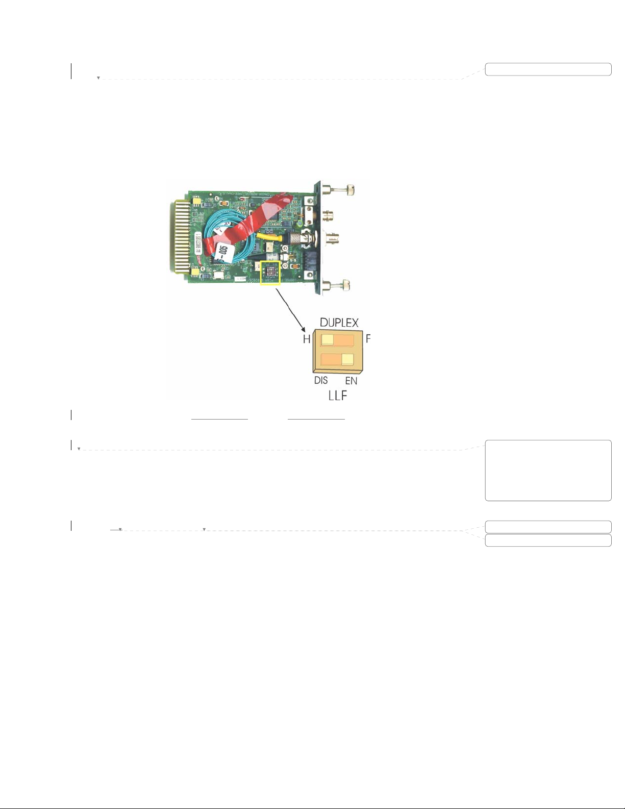
1.7 Quick Start Configuration of the 10BASE-
FL/100BASE-FX Interfaces
The 9135 Two-Port and 9140 Four-Port Switch feature 10Mbps and 100Mbps fiber optic interfaces, with a
wide choice of optical connector and wavelength options. These interfaces can be configured for half or
full-duplex operation, based on the settings of DIP switches found on the respective interface cards.
Step 1 Remove the optical interface from the Switch by unscrewing the front panel captive screws and
pulling the interface out of the unit. Locate the two position DIP switch as shown in Figure 1-6,
and set the switches to the appropriate settings for your specific application.
Deleted: 5
Figure 1-6. 91
00 Series SMF Interface.
DIP 1 FDX When set to the on, or enabled position, the interface will be configured for
full-duplex operation. In the off or disabled position, the interface will be set for
half-duplex operation.
DIP 2 LLFen The 9135 supports LLF when the units are non managed. When the 9100-M
manager module is inserted, the LLF feature is automatically disabled. The 9140
does not support LLF, neither managed or non managed configurations.
Step 2 Rei
nsert the UTP interface into the 9135 Two-Port Switch or 9140 Four-Port Switch and tighten
the captive screws down. When the correct UTP and fiber cable attachments are completed, the
Interface LEDs will provide indications that reflect the dip switch settings. Refer to Section 1.8,
"Quick Start Interface Connection," for detailed information on the LEDs.
Note: Although the 9135 and 9140 is designed to soft reset whenever a card is inserted, it may not always
do so; therefore, after inserting a card, monitor the unit for a reset. If the unit fails to do so, force a reset
manually by depressing the reset button on the right side of the unit.
1-8
Deleted: 
Deleted: I
Deleted: back
EdgeAccess SNMP Managed Fast Ethernet Switch
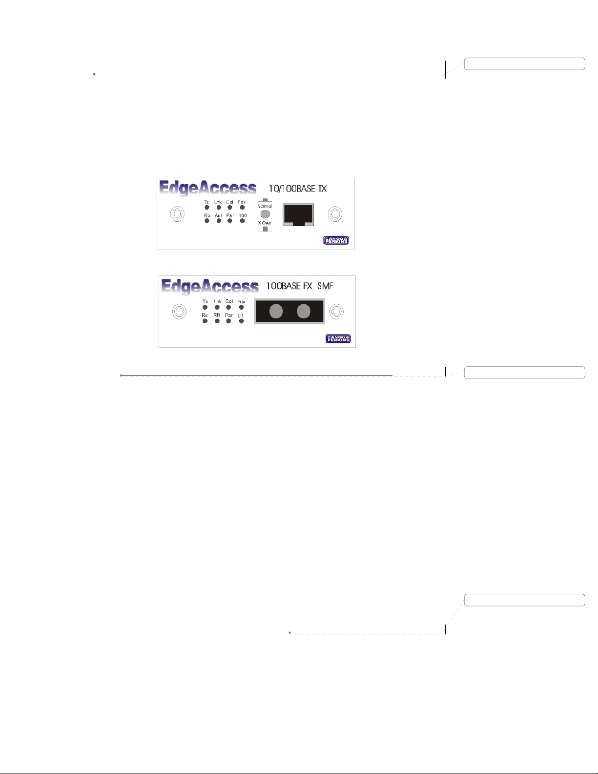
1.8 Quick Start Interface Connection
Caution: To protect the Ethernet port from an intrabuilding lightening surge, use a properly grounded
shielded cable.
Step 1 In this installation step, connect the Category 5 UTP jumper cable from the customer's equipment
into the RJ-45 receptacle on the 10/100BASE-TX module. Reference Figure 1-7.
Note: Step 1 must be repeated on both local and remote switches.
Deleted: 6
Figure 1-7. 9135 or 9140 UTP and SMF Interface Connectors and LEDs.
Step 2 The following LEDs verify the correct operation of the local and remote switch UTP interface,
the CAT 5 UTP jumper cable, and the 9135 or 9140 10/100BASE-TX UTP interface.
Lnk ON Indicates that good idle signals are received from the other UTP
interface transmitter via the UTP cable.
Aut ON This indicates auto negotiation is active.
100 ON This indicates 100Mbps operation.
OFF This indicates 10Mbps operation.
Fdx mode ON This indicates that the unit is in full-duplex mode.
OFF This indicates that the unit is in half-duplex mode.
Step 3 Connect the fiber optic jumper cable from the fiber patch panel or other 9135/9140 switch and
insert into the 100BASE-FX connector on the 9135/9140 optical interface.
Note: This step must be repeated on both local and remote 9135 or 9140 100BASE-FX interfaces.
Model 9135/9140
Formatted
Deleted: Page of 871
1-9
Step 4 Once connected, the correct operation of the local 100BASE-FX SMF interface, SMF optic cable
Lnk ON Indicates that good idle signals are received from the other interface's
transmitter via the optical cable.
Fdx mode ON This indicates that the unit is in full-duplex Mode; Off indicates half-
Llf ON This indicates that the link loss forwarding is enabled and operational.
Note: The 9140 Four-Port Switch does not support LLF and therefore will ignore that setting in any
installed interface.
and remote 100BASE-FX SMF interfaces can be verified by checking the following LEDs:
duplex.
1.9 Quick Start Management Module Cable Attachment
Configure the SNMP Manager as follows:
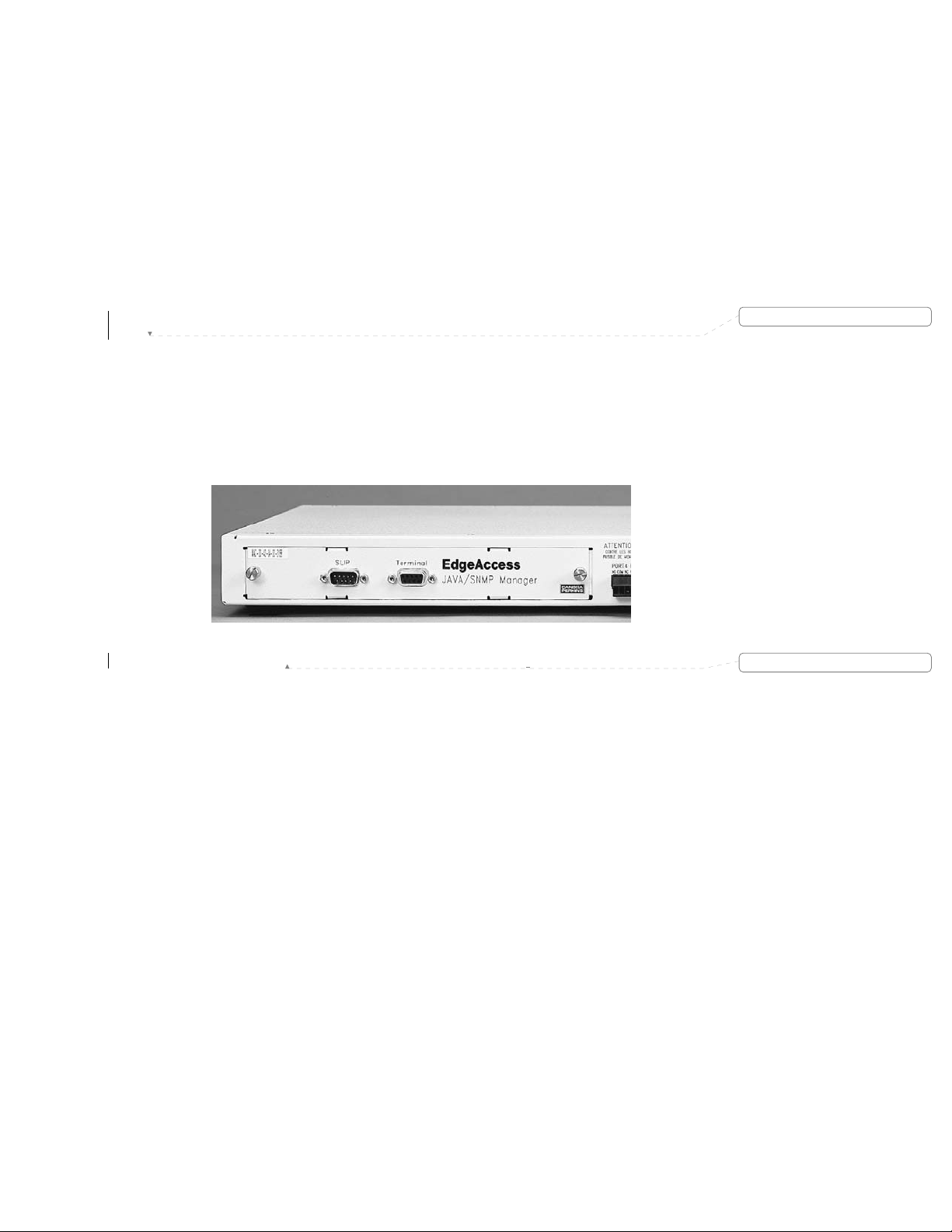
Step 1 Locate the SNMP Management module on the rear panel of the 9135 Two-Port or 9140 Four-Port
Switch as shown in Figure 1-8. You will see a label with the MAC (Media Access Control)
address printed on it affixed to the module. This address is unique to the unit, so make note of it
for future reference.
Deleted: 7
Step 2 Using a straight through serial cable with DE-9 male and female connectors, insert the male end
Note: Laptops typically have a DE-9 male connector, whereas desktop units may differ.
1-10
into the connector marked "Terminal" on the SNMP Management module. Connect the DE-9
female end to the male serial interface on the back of your PC.
Figure 1-8. SNMP Management Module.
Formatted
EdgeAccess SNMP Managed Fast Ethernet Switch
1.10 Quick Start PC Configuration for Terminal Operation
The following explanation assumes Windows 95/98 is installed and operational. Windows NT screens may
differ. Refer to the appropriate Windows NT manual.
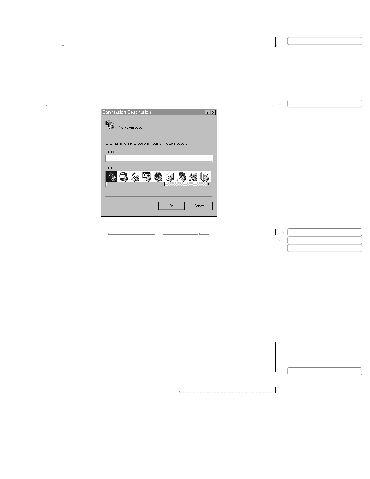
Step 1 Power up your PC. When the main Windows screen displays, click on the Start icon.
Highlight Programs > Accessories then click on the HyperTerminal. See Figure 1-9.
Deleted: 8
Formatted
Figure 1-9. Naming
the HyperTerminal File.
Step 2 The HyperTerminal program will open and prompt you to set up the terminal operation for the
9135 Two-Port or 9140 Four-Port Switch, as shown in Figure 1-9. Enter a name for the unit,
choose an icon for the connection and click OK.
Model 9135/9140
Formatted
Formatted
Formatted
Deleted: Page of 871
1-11
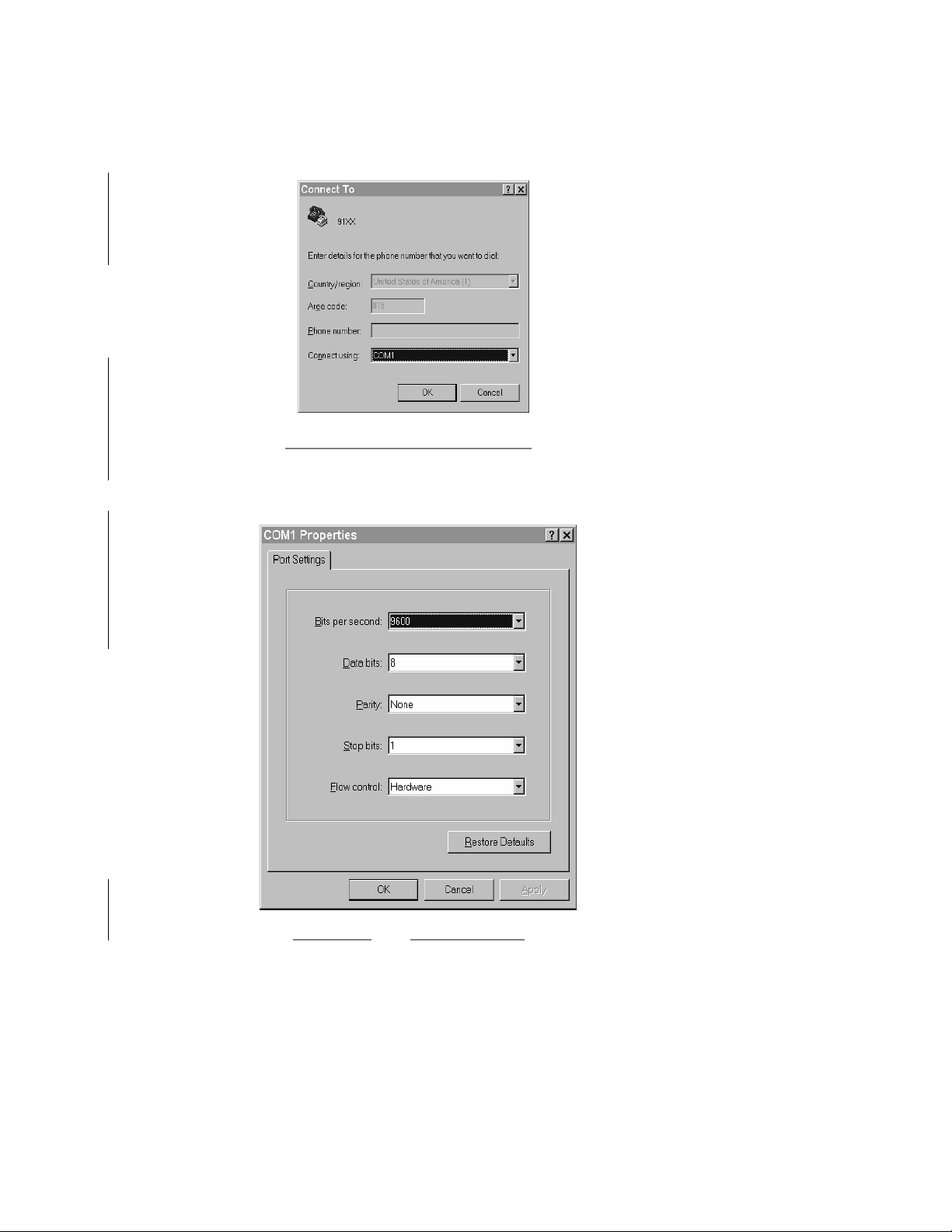
Step 3 Select COM1 from the Connect using drop down menu as shown in Figure 1-10 and click OK.
Note: Most computers use COM2 for the serial mouse, leaving COM1 available for terminal connection.
However, the user should verify the appropriate serial port.
Figure 1-10. COM Port Selection Screen.
Step 4 Enter the COM1 parameters as shown in Figure 1-11, and click OK.
Figure 1-11. COM1 Properties Screen.
1-12
EdgeAccess SNMP Managed Fast Ethernet Switch
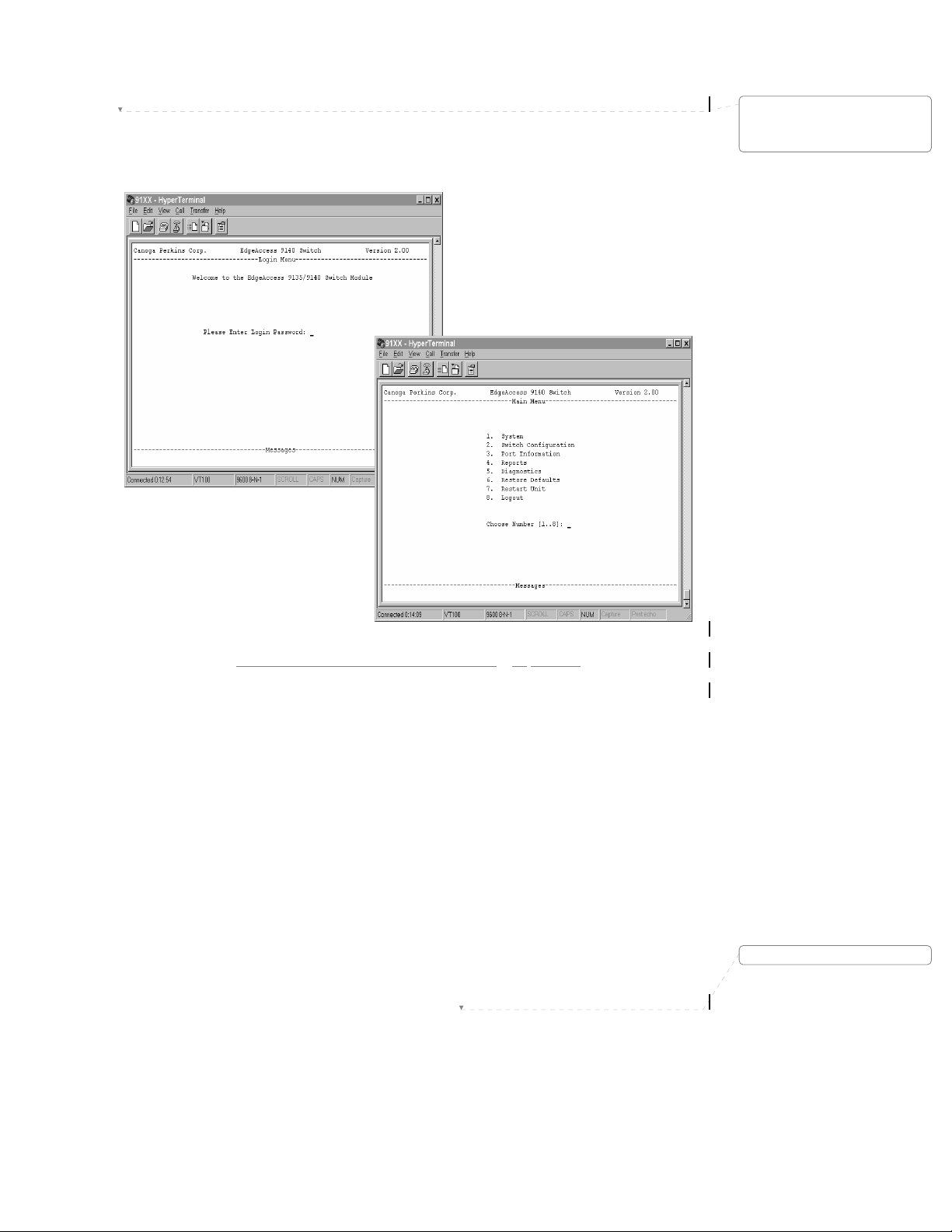
Step 5 At this point the HyperTerminal program will open the newly created 9135/9140 Switch Terminal
as shown in Figure 1-12. Note the screen succession will be, Login Menu (enter password), and
the Main Menu.
Deleted: 
Figure 1-12. Opening Screens for the 9135/
9140 SW File.
Step 6 When configured correctly, HyperTerminal will open and prompt you to enter a "Password." If
this is your initial setup, no password has yet to be defined, so you will select <Enter>. If this is
not your initial setup, enter the proper password as established for Supervisor, Manager, or User,
and select <Enter>. The Main Menu will appear. See Figure 1-12.
At this point the terminal has been correctly configured and is operational. The following Section
details how to configure the 9135 for in-band management.
Note: The terminal operation has an automatic "logout" function after 10 minutes of idle time.
Model 9135/9140
Deleted: Page of 871
1-13

This page is intentionally left blank.
1-14
EdgeAccess SNMP Managed Fast Ethernet Switch
Chapter 2
Overview
2.1 EdgeAccess 9135 Two-Port and 9140 Four-Port
Fast Ethernet Switch
The Canoga Perkins EdgeAccess 9135 Two-Port and 9140 Four-Port Fast Ethernet Switch, shown in figure
2-1, are key components of the EdgeAccess family. They are designed to provide IT Managers and
Network Analysts with a flexible and modular-managed 10/100Mbps LAN platform. Each switched port
on the 9135 Two-Port Switch and 9140 Four-Port Switch can be populated by 10Mbps or 100Mbps
interfaces. Additionally the most appropriate media can be selected from a wide range of copper or fiber,
single mode and multimode, plug-in interface modules. The 9135 and 9140 Switch support IEEE 802.3 and
IEEE 802.1d standards. When the 9100-M or 9100-QTC cards are installed, the 9135/9140 will pass, but
not participate in 802.1Q 1522 byte VLAN tagged packets.
The 9140 will support single and redundant link applications. However,
supported on ports 1 and 2 only at 100Mbps.
redundant link applications are
Deleted: However
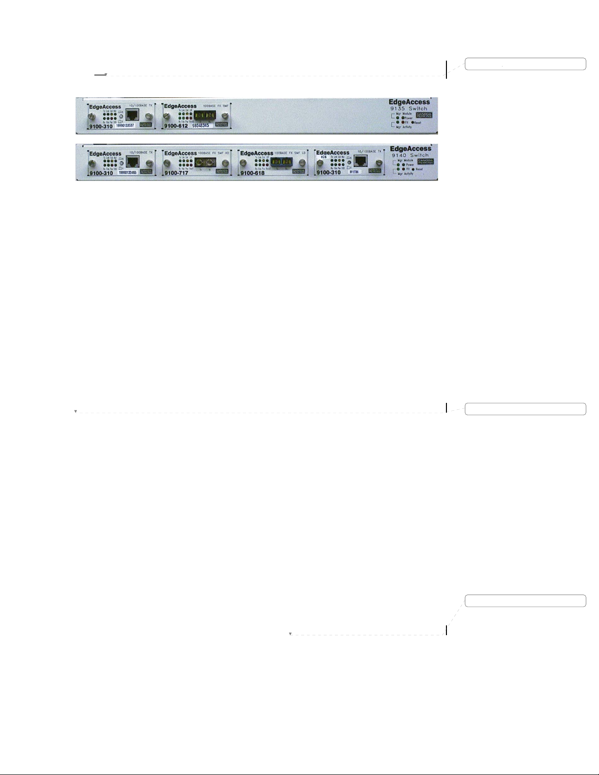
Figure 2-1. 9135 Two-Port and 9140 Four-Port Fast Ethernet Switch (Front Panel).
The base unit features two (9135) or four (9140) hot-swappable plug-in interface slots in the front and a
SNMP management slot in the back. Plug-in slots can be populated with the following interface modules:
• 9100-300: Software controlled 10 or 100BASE-TX, UTP
9100-310: 10/100BASE-TX UTP copper interface with an RJ-45 shielded connector
•
• 9100-100: 10BASE-5 STD AUI interface for attachment to transceivers
• 9100-101: 10BASE-5 Switch AUI for attachment to routers and switches
• 9100-401: 10BASE-FL 850nm MM fiber with ST connectors and 15 dB optical budget
• 9100-601: 10BASE-FL 1310nm SM fiber with ST connectors and 20dB optical budget
• 9100-603: 10BASE-FL 1310nm SM fiber with FC/PC connectors and 20dB optical budget
• 9100-604: 10BASE-FL 1310nm SM fiber with ST connectors and 10dB optical budget
• 9100-605: 10BASE-FL 1310nm SM fiber with FC/PC connectors and 10dB optical budget
• 9100-607: 10BASE-FL 1310nm SM fiber with ST connectors and 25dB optical budget
• 9100-608: 10BASE-FL 1310nm SM fiber with FC/PC connectors and 25dB optical budget
• 9100-707: 10BASE-FL 1550nm SM fiber with ST connectors and 26dB optical budget
• 9100-708: 10BASE-FL 1550nm SM fiber with FC/PC connectors and 26dB optical budget
• 9100-411: 100BASE-FX 1310nm MM fiber with ST Duplex connectors and 11dB
• 9100-412: 100BASE-FX 1310nm MM fiber with SC Duplex connectors and 11dB
9100-611: 100BASE-FX 1310nm single mode fiber with ST Duplex connectors and
•
9100-612: 100BASE-FX 1310nm single mode fiber with SC Duplex connectors and
•
optical budget
optical budget
10dB optical budget
10dB optical budget
Deleted: 
Deleted:
Formatted: Bullets and Numbering
Deleted:
Deleted:
Formatted: Bullets and Numbering
Formatted: Bullets and Numbering
Deleted: Page of 871
Model 9135/9140
2-1
9100-617: 100BASE-FX 1300nm SM fiber with ST Duplex connectors and
•
26dB optical budget
• 9100-618: 100BASE-FX 1300nm SM fiber with SC Duplex connectors and
26dB optical budget
• 9100-717: 100BASE-FX 1550nm SM fiber with ST Duplex connectors and
26dB optical budget
9100 718: 100BASE-FX 1550nm SM fiber with SC Duplex connectors and
•
26dB optical budget
• 9100-M: SNMP Management Module
• 9100-QTC: 802.1Q mode for passing 1522 byte VLAN tagged packets
The 9140 Four-Port Switch, in conjunction with its wide selection of interface options and other
EdgeAccess products, can be used in a variety of configurations to meet a wide range of networking
requirements.
2.2 Main Features
The 9135 Two-Port Switch and 9140 Four-Port Switch provides the following features:
Plug-in hot-swappable 10 and 100Mbps copper and fiber interface modules
•
• Supports IEEE 802.1d bridging specifications (with management module installed)
• Store and Forward operation
• Supports half-and full-duplex on all ports (except AUI modules)
• Non-Blocking switch
• Full wire speed 148,800 frames per second on all ports
• Supports Spanning Tree algorithm (with management module installed)
• 100Mbps Fiber Optic Link Redundancy (9140 only)
Address table supports 8,000 entries maximum
•
• One Megabyte of packet and address table memory per port
• Supports IEEE 802.1Q 1522 byte tagged packets with optional 9100-M manager or 9100-QTC card
The 9140 Four-Port Switch main board layout is designed to support four (two for the 9135) Fast Ethernet
switched ports with any required combination of copper or fiber ports. The main board contains:
Two switch ASIC device chips (one on the 9135)
•
• Four Megabytes of Packet and Address Table memory; one Megabyte per port (two Megabytes of
Packet and Address Table memory on the 9135)
Connectors:
•
• PCI connector for management board
• Four edge M11 (two for the 9135) connectors for connecting plug-in interface modules
• Alarm Relay contacts connector
• Reset push button; recessed and located on the front panel
The optional Management Module is hot-swappable and field upgradeable, and can be initialized after
installation by pressing the reset push button. The Management Module board contains:
RISC CPU i960RP - 33 MHz with integrated PCI interface
•
• Hardware and software watchdog for automatic recovery
• DRAM - 4 MB
• BOOT EPROM - 125kb/512kb
• Two banks of one Megabyte flash memory for software upgrades
• Serial EIA 232 Port for terminal configurations (DE-9 Female DCE)
• Serial EIA 232 for remote management and monitoring (DE-9, Male DTE) with modem support
• Onboard CPU JTAG connector
• PCI connector to the main board
Formatted: Bullets and Numbering
Formatted: Bullets and Numbering
Deleted:
Formatted: Bullets and Numbering
Formatted: Bullets and Numbering
Formatted: Bullets and Numbering
Formatted: Bullets and Numbering
2-2

EdgeAccess SNMP Managed Fast Ethernet Switch
Chapter 3
Installation and Setup
3.1 Installation
This section provides instruction on how to install and operate the 9135 Two-Port and 9140 Four-Port
Switch. The units can be installed in the following manner:
a standard 19-inch relay rack
•
• a 23-inch relay rack with optional RM-1U-23 Kit
• wall mounted
• a stand alone unit in a table top configuration
3.1.1 Unpacking
The 9135 Two-Port Switch and 9140 Four-Port Switch are tested and inspected prior to shipment from the
factory. In the event that there is obvious damage to the shipping container, contact the carrier involved.
It is recommended that you keep the shipping package until the unit has been installed and verified as being
fully operational. In the unlikely event that the unit is defective, contact the Canoga Perkins Customer
Service Department for a Return Material Authorization (RMA) number and for instructions on how to
return the unit. Refer to Appendix D.
Canoga Perkins products, like all electronic devices with static sensitive components, should be handled
with care.
3.1.2 Rack Mount Installation
The rack mount kit contains rack mount ears and four screws. These enable you to attach the 9135 or 9140
in a standard 19-inch relay rack or 23-inch relay rack with optional RM-1U-23 Kit. You may opt for a front
chassis or mid chassis mount as shown in Figure 3-1.
For front chassis mount, place a rack mount ear on the right side of the Switch flush with the front panel
such that the three screw holes on the units and the rack mount ear are lined up. Insert the screws and
tighten. Perform the same operation for the left side.
For mid chassis mount, place a rack mount ear on the right side of the Switch such that the three midchassis screw holes of the units and the rack mount ears are lined up. Insert the screws and tighten. Perform
the same operation for the left side.
Formatted
Deleted:
Formatted: Bullets and Numbering
Deleted:
Deleted:
Front Chassis Mount s crewholes Mid Chassis Mount screwholes
Figure 3-1. Installing Rack Mount Ears.
Model 9135/9140
Deleted: Page of 871
3-1
3.1.3 Wall Mount Install ation
a
For a Wall Mount installation, the 9135 and 9140 Four-Port Switch feature two wall mount holes located
on the bottom of the unit. A template for wall mounting is included in the unit package. These allow you to
mount the Switch in locations that have space limitations. The holes on the Switch are located on a 9.5-inch
center as shown in Figure 3-2. Insert the screws (not included) into the wall on the 9.5-inch center so that
they line up with the wall mount holes on the Switch and carefully set it onto the screws.
Note: A flat head wood or sheet metal screw is recommended.
Screw holes for
ll Mount
W
3-2. Wall mount
Figure
Installation.
Bottom View of the 9135/9140
3.1.4 Stand Alone Installation
If you are using the 9135 Two-Port Switch or 9140 Four-Port Switch as a stand-alone unit, place it on a
secure, flat surface. Ensure that the unit is within reach of the necessary connections:
Power outlet
•
• Ethernet connections
As with all electronic devices, ensure adequate airflow is provided around the unit since some heat is
generated. Make sure the fan, Figure 3-3, on the rear panel is not blocked.
Deleted:
Deleted:
Formatted: Bullets and Numbering
Figure 3-3. Fan Assembly and Power Entry Socket.
3-2
EdgeAccess SNMP Managed Fast Ethernet Switch
3.2 Setup
Figure 3-4. Front View of the 9135 Two-Port Switch and 9140 Four-Port Switch.
The first step in setting up the 9135 Two-Port Switch or the 9140 Four-Port Switch is to choose the
interface modules necessary for the application to be implemented. The modules are hot swappable and do
not require a powering down of the unit. Setup and install the selected module using the following steps:
Step 1 Remove any currently installed modules by loosening the captive screws and extracting the
module from the 9135 Two-Port Switch or 9140 Four-Port Switch.
Step 2 Set or verify the internal DIP switches, located on the front panel, to the desired module for the
desired operational configuration. Refer to Sections 3.2.1 through 3.2.6 for available options.
Step 3 Insert it into the opening on the front panel. Insure that the module is connected snugly into the
receptor inside the 9140 Four-Port Switch. Tighten the captive screws on the front of the module.
Note: After installing a hot swappable module in an operating unit, use a nonconductive stylus to press the
reset button, located on the main chassis front panel with the Manager LED group.
Deleted:
Deleted: 
Model 9135/9140
Deleted: Page of 871
3-3

3.2.1 9100-300 10/100BASE-TX Module
This module is a plug-in, which contains the 10/100BASE-TX interface, see Figure 3-5.
Caution: To protect the Ethernet port from an intrabuilding lightening surge, use a properly grounded
shielded cable.
This interface provides 10 and 100Mbps operation, using UTP cables. The interface components are the
following:
• RJ-45 shielded connector
• Port LEDs
• Tx Transmit (Green)
• Lnk Link (Green)
• Col Collision (Yellow)
• Fdx Half/Full-Duplex (Green)
• Rx Receive (Green)
• Aut Auto negotiation enabled (Green)
• Par Partition/Disable (Red)
• 100 100Mbps indication (Green)
• Connectors: Edge connector to the main board unit
• UTP Crossover Switch
The 10/100BASE TX interface modules can be configured to connect to either standard DTE devices, or to
repeaters, which usually cross their XMT and RCV pairs internally, without the need for special crossover
cables.
To connect the 10/100BASE TX interface modules to a standard DTE device with a standard straightthrough cable, set the Normal/Crossover switch, which is internally crossed, to the X position, switch
button OUT, shown in Figure 3-5.
To connect the 10/100BASE TX interface modules port marked with an X, as with most repeaters with a
standard straight-through cable, set the Normal/Crossover switch to the N position, switch button N, shown
in Figure 3-5.
Set the interface to 10 BASE -TX or 100 BASE-TX in software. For details, see Chapter 5.
Figure 3-5. 10/100BASE TX Inte rf ac e Mod ul e.
3-4
 Loading...