

CANOGA PERKINS 9135 SNMP User Manual

Model 9135 SNMP
Managed 10/100/1000
Ethernet Switch
User Manual


EdgeAccess Universal Chassis System
CAUTION!
This product may contain a laser diode operating at a wavelength of 1300nm - 1600nm. Use of
optical instruments (e.g., collimating optics) with this product may increase eye hazard. Use of
controls or adjustments, or performing procedures other than those specified herein may result in
hazardous radiation exposure.
Under normal conditions, the radiation levels emitted by this product are under Class 1 limits in 21
CFR Chapter 1, Subchapter J.
ATTENCION!
Cet équipement peut avoir une diode laser émettant à des longueurs d'onde allant de 1300nm à
1600nm. L'utilisation d'instruments optiques (par exemple : un collimateur optique) avec cet
équipement peut s'avèrer dangereuse pour les yeux. Procéder à des contrôles, des ajustements ou toute
procédure autre que celles décrites ci-après peut provoquer une exposition dangereuse à des
radiations.
Sous des conditions normales, le niveau des radiations émises par cet équipement est en dessous des
limites prescrites dans CFR21, chapitre 1, sous chapitre J.
NOTICE!
This device contains static sensitive components. It should be handled only with proper ElectroStatic
Discharge (ESD) grounding procedures.
NOTE!
Cet équipement contient des composants sensibles aux décharges électro-statiques. Il doit absolument
être manipulé en respectant les règles de mise à la terre afin de prévenir de telles décharges.
Model 9135 10/100/1000
i

EdgeAccess Universal Chassis System
NOTICE
Canoga Perkins has prepared this users manual for use by customers and Canoga Perkins personnel as
a guide for the proper installation, operation and/or maintenance of Canoga Perkins equipment. The
drawings, specifications and information contained in this document are the property of Canoga
Perkins and any unauthorized use or disclosure of such drawings, specifications and information is
prohibited.
Canoga Perkins reserves the right to change or update the contents of this manual and to change the
specifications of its products at any time without prior notification. Every effort has been made to
keep the information in this document current and accurate as of the date of publication or revision.
However, no guarantee is given or implied that the document is error free or that is accurate with
regard to any specification.
Canoga Perkins Corporation
20600 Prairie Street
Chatsworth, California 91311-6008
Business Phone: (818) 718-6300
(Monday - Friday 7 a.m. - 5 p.m. Pacific Time)
FAX: (818) 718-6312 (24hrs.)
Web Site: www.canoga.com
Email: fiber@canoga.com
Copyright© 2003 - 2005 Canoga Perkins Corporation
All Rights Reserved
EdgeAccess
Model 9135
SNMP Managed Ethernet 10/100/1000 Switch
User Manual
Model Number 9135-UM
Product Number 6912851
Rev. D 09/2005
®
ii
Model 9135 10/100/1000

EdgeAccess Universal Chassis System
Table of Contents
Chapter 1 Overview ................................................................................................ 1-1
1.1 Data Switch Features .............................................................................................................. 1-1
1.2 Hardware Management Features ............................................................................................ 1-2
Chapter 2 Setup and Installation ........................................................................... 2-1
2.1 Install the 9135 ....................................................................................................................... 2-1
2.2 LEDs ....................................................................................................................................... 2-4
Chapter 3 Management .......................................................................................... 3-1
3.1 Set Up the Serial Port ............................................................................................................. 3-1
3.2 Management User Interface....................................................................................................3-1
3.3 Using the 9135 Management Program ................................................................................... 3-2
3.4 System Menu .......................................................................................................................... 3-3
3.4.1 IP Settings.............................................................................................................................. 3-4
3.4.2 Host Table / SNMP Settings.................................................................................................. 3-6
3.4.3 SLIP Port Settings.................................................................................................................. 3-7
3.4.4 Passwords .............................................................................................................................. 3-8
3.5 Switch Configuration and Spanning Tree............................................................................. 3-10
3.5.1 Global Spanning Tree Parameters ....................................................................................... 3-11
3.5.2 Port Spanning Tree Parameters ........................................................................................... 3-12
3.5.3 Spanning Tree Report.......................................................................................................... 3-14
3.6 Port Information.................................................................................................................... 3-15
3.7 Reports.................................................................................................................................. 3-17
3.7.1 Description Report Screen................................................................................................... 3-17
3.7.2 Traps Log Screen................................................................................................................. 3-17
3.7.3 Fdb Log Screen.................................................................................................................... 3-18
3.8 Diagnostics ........................................................................................................................... 3-19
3.9 Restore Defaults.................................................................................................................... 3-20
3.10 Restart Unit.......................................................................................................................... 3-20
3.11 Logout.................................................................................................................................. 3-21
3.12 Update the Software Through TFTP ................................................................................... 3-21
3.13 Update the Software Through FTP...................................................................................... 3-22
Chapter 4 SLIP Connection ................................................................................... 4-1
4.1 Configuring the 9135 for SLIP ............................................................................................... 4-1
4.2 Setting up the SLIP Connection on the PC............................................................................. 4-1
4.3 Launching a SLIP Connection................................................................................................ 4-2
Chapter 5 Specifications ......................................................................................... 5-1
5.1 Switch Specifications.............................................................................................................. 5-1
5.2 9135 Ports and Pinouts ........................................................................................................... 5-2
5.3 Regulatory Compliance and Referenced Documents ............................................................. 5-3
5.4 Interfaces and Connectors....................................................................................................... 5-3
Model 9135 10/100/1000
iii

EdgeAccess Universal Chassis System
Appendix A Warranty............................................................................................ A-1
Appendix B Acronyms............................................................................................ B-1
List of Figures
Figure 1. 9135 SNMP Managed Ethernet Switch ..............................................................................1-1
Figure 2. SW1 on UTP Copper Interface ........................................................................................... 2-1
Figure 3. SW1 on 100 Base Modules, Fiber Optic Interface .............................................................2-2
Figure 4. SW1 on 1000 Base Modules, Fiber Optic Interface ........................................................... 2-2
Figure 5. Typical 9135 Screen ...........................................................................................................3-2
Figure 6. The 9135 Login Menu ........................................................................................................ 3-2
Figure 7. Main Menu..........................................................................................................................3-3
Figure 8. System Menu ......................................................................................................................3-3
Figure 9. IP Settings...........................................................................................................................3-4
Figure 10. Host Table / SNMP Settings Menu................................................................................... 3-7
Figure 11. SLIP Port Settings Menu ..................................................................................................3-8
Figure 12. Passwords Menu ...............................................................................................................3-9
Figure 13. Switch Configuration Menu............................................................................................3-10
Figure 14. Typical Spanning Tree Application................................................................................3-11
Figure 15. Spanning Tree Parameters Menu.................................................................................... 3-11
Figure 16. Global Spanning Tree Parameters Menu ........................................................................3-12
Figure 17. Port Spanning Tree Parameters Report and Menu..........................................................3-13
Figure 18. Spanning Tree Report Screen .........................................................................................3-14
Figure 19. Ports Information Screen ................................................................................................ 3-15
Figure 20. Port n Information Screen...............................................................................................3-16
Figure 21. Single Port Statistics Screen ...........................................................................................3-16
Figure 22. All Ports Statistics Screen............................................................................................... 3-16
Figure 23. Reports Menu..................................................................................................................3-17
Figure 24. Description Screen.......................................................................................................... 3-17
Figure 25. Traps Log Screen............................................................................................................3-18
Figure 26. Fdb Log Screen............................................................................................................... 3-19
Figure 27. Diagnostics Menu ...........................................................................................................3-19
Figure 28. Ping Menu.......................................................................................................................3-20
Figure 29. Restore Defaults Option.................................................................................................. 3-20
Figure 30. Restart Unit Menu...........................................................................................................3-21
iv
Model 9135 10/100/1000

EdgeAccess Universal Chassis System
List of Tables
Table 1. SW1 Settings, UTP Copper Interface.................................................................................. 2-1
Table 2. SW1 Settings, 100 Base Modules, Fiber Optic Interface .................................................... 2-2
Table 3. SW1 Settings, 1000 Base Modules, Fiber Optic Interface .................................................. 2-3
Table 4. 9135 Management LEDs..................................................................................................... 2-4
Table 5. 9135 Interface Module LEDs .............................................................................................. 2-5
Table 6. Main Menu Options............................................................................................................. 3-3
Table 7. System Menu Options.......................................................................................................... 3-4
Table 8. IP Settings Menu Options.................................................................................................... 3-5
Table 9. IP Address and Subnet Mask............................................................................................... 3-5
Table 10. SLIP Port Settings Options................................................................................................ 3-8
Table 11. Password Access Levels by Menu..................................................................................... 3-9
Table 12. Spanning Tree Parameters Options ................................................................................. 3-11
Table 13. Global Spanning Tree Parameters Menu Options ........................................................... 3-12
Table 14. Port Spanning Tree Parameters Report............................................................................ 3-13
Table 15. Port Spanning Tree Parameters Menu Options................................................................ 3-13
Table 16. Spanning Tree Report...................................................................................................... 3-14
Table 17. Terminal Port, Female DE-9.............................................................................................. 5-2
Table 18. SLIP Port, Male DE-9........................................................................................................ 5-2
Model 9135 10/100/1000
v

EdgeAccess Universal Chassis System
vi
Model 9135 10/100/1000
EdgeAccess Universal Chassis System
Chapter 1 Overview
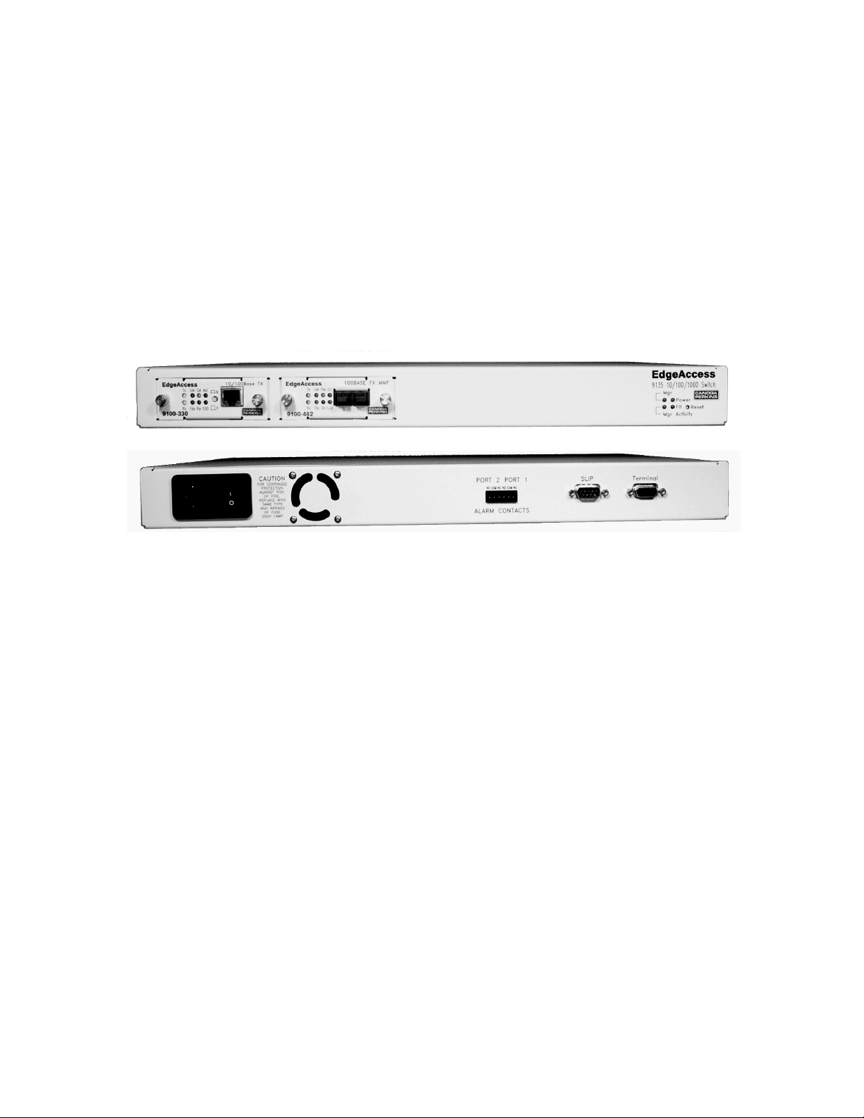
The Canoga Perkins EdgeAccess 9135 is an SNMP Managed, two-port Ethernet Switch that provides
Managers and Network Analysts with a modular-managed 10/100 or 1000 Mbps LAN platform. See
Figure 1. The 9135 switch supports two 10, 100, or 1000 Mbps interface modules. The hotswappable interface modules provide these options:
• 850 nm multimode, 1310 nm multimode, 1310 nm single mode, or 1550 nm single mode
• ST, SC, FC/PC, or duplex SC connectors
The 9135 supports IEEE 802.1d and 802.1Q standards.
Figure 1. 9135 SNMP Managed Ethernet Switch
1.1 Data Switch Features
The 9135 includes these features for the data switch:
• Store and forward operation
• Full- and half-duplex data transfer
• Non-blocking switch
• Full wire speed
• Spanning tree algorithm
• Address table supports 1,000 entries
• Multiple VLAN tagged frames
Model 9135 10/100/1000
1-1

EdgeAccess Universal Chassis System
1.2 Hardware Management Features
The 9135 includes these hardware features for switch management:
• Alarm relay contacts that can transmit these fault conditions for each port.
• Loss of link integrity
• Remote fault
• Power failure
• SNMP
• Hardware and software watchdog for automatic recovery
• Serial EIA-232 Port that provides:
• Terminal Interface for terminal configurations (DE-9 female DTE)
• SLIP Interface for remote management and monitoring (DE-9 male DCE)
1-2
Model 9135 10/100/1000

EdgeAccess Universal Chassis System
Chapter 2 Setup and Installation
This section describes how to install the 9135 and the interface modules.
Caution Equipment intended only for installation in a RESTRICTED ACCESS LOCATION
accessible only to electrically skilled persons and electrically instructed persons with
the proper authorization.
2.1 Install the 9135
The 9135 is tested and inspected before shipment from the factory. If there is obvious damage to the
shipping container, contact the carrier immediately.
Caution: Follow electrostatic discharge (ESD) safety precautions when handling Canoga
Perkins products, as with all electronic devices with static sensitive components.
1. Unpack the 9135. Keep the shipping container until the unit is installed and fully operational. In
the unlikely event that the unit is defective, contact Canoga Perkins Customer Service for a return
authorization number (RMA) and instructions on return shipment. For details, see Appendix A.
2. On the UTP copper interface (9100-330), set SW1 for your system; see Figure 2 and Table 1.
SW1
Figure 2. SW1 on UTP Copper Interface
Table 1. SW1 Settings, UTP Copper Interface
Switch Name On Off
1-1 10 or 100 Mbps 100 Mbps 10 Mbps
1-2 FDX Full-duplex Half-duplex
1-3 AUT (Auto
negotiation)
1-4 LLF Enable Link Loss Forward (LLF) Disable LLF
Manages the fastest common operating mode
between this module and its link partner
Model 9135 10/100/1000
Follow SW1-1 and 1-2
settings
2-1
EdgeAccess Universal Chassis System
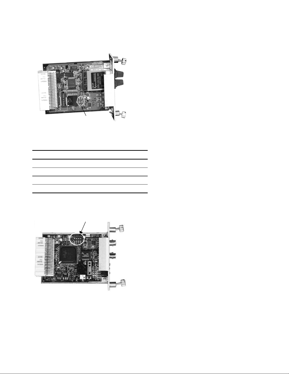
3. On the 100 Base modules, fiber optic interface (9100-44x, -54x, -64x, or -74x), set SW1 for your
system; see Figure 3 and Table 2.
SW1
Figure 3. SW1 on 100 Base Modules, Fiber Optic Interface
Table 2. SW1 Settings, 100 Base Modules, Fiber Optic Interface
Switch Name On Off
1-1 FDX Full-duplex Half-duplex
1-2 LLF Enable LLF Disable LLF
1-3 LLE Enable LLE Disable LLE
1-4 Not used
4. On the 1000 Base modules, fiber optic interface (9100-55x, -65x, -75x, or -95x), set SW1 for
your system; see Figure 4 and Table 3.
SW1
Figure 4. SW1 on 1000 Base Modules, Fiber Optic Interface
2-2
Model 9135 10/100/1000

EdgeAccess Universal Chassis System
Table 3. SW1 Settings, 1000 Base Modules, Fiber Optic Interface
Switch Name On Off
1-1 LLF Enable LLF Disable LLF
1-2 LLE Enable LLE Disable LLE
5. Mount the 9135 in a rack or as a standalone unit.
• Use the standard rackmount kit with brackets and screws to install the 9135 in a 19-inch rack or
use the optional 23-inch rackmount kit. The 9135 includes two sets of mounting holes.
• For a front chassis mount, align the screw holes in the brackets with the screw holes at the
front of the side panel of the 9135G, then secure the screws.
• For a mid- or recessed chassis mount, align the screw holes in the brackets with the screw
holes in the middle of the side panel of the 9135, then secure the screws.
• To use the 9135 as a standalone unit, place it on a secure, flat surface within reach of the power
and fiber optic connections
6. Connect the power. The 9135 can be equipped for either AC or DC power.
• Plug the AC power cord into the socket at the rear of the 9135 and the wall socket.
Caution: Reversing the connections can damage both the DC source and the 9135.
• Connect power for the -48VDC power supply.
• For a -48VDC source, connect the grounding strap between the Chassis Ground and the
+VDC terminals.
• For a +48VDC source, connect the grounding strap between the Chassis Ground and the
-VDC terminals.
7. Connect the alarms. The alarm contacts for the 9135 are located next to the SLIP Port on the rear
panel; see Figure 1. The relay alarm contacts provide both normally open and normally closed
contacts for each port:
• NO The contacts are open for normal operation and closed in a fault condition
• COM The electrical common
• NC The contacts are closed for normal operation and open in a fault condition
8. Install the interface modules:
a. Insert a module into a slot and push firmly on the center of the front panel. If it does not seat
properly, pull the module out, inspect for bent connector pins, and reinsert it.
b. When the module is firmly seated, hand-tighten the screws on the front panel.
Cabling for the 9135 includes the serial cable(s) to the SLIP and Terminal port(s), the Ethernet cable,
and the fiber optic link to the Tx and Rx ports.
9. Plug the serial cable into the SLIP or Terminal port on the rear panel and your PC. For the
pinouts, see Chapter 5, Specifications.
• The EIA 232 Terminal port provides serial access to the management software.
• The SLIP port provides serial or modem access to the management software.
Model 9135 10/100/1000
2-3

EdgeAccess Universal Chassis System
Dirty optical connectors are a common cause of link loss or attenuation problems, especially for
single mode fiber (SMF). Clean the connectors before plugging in a cable and whenever there is a
significant or unexplained light loss. To prevent contamination, always install protective dust covers
on unused fiber optic connectors.
10. Wipe the ferrule and the end-face surface of the male fiber coupler with a lint-free, isopropyl
alcohol pad from a fiber cleaning kit.
11. Use canned air to blow any dust out of the female fiber coupler.
Caution: To avoid damaging the fiber end-surface or connector, use extreme care when
installing or removing cables.
12. Plug in the optical cables with primary to primary, secondary to secondary, and Tx to Rx, Rx to
Tx orientation.
Caution: To protect the Ethernet port from an intrabuilding lightning surge, use a properly
grounded shielded cable.
13. Plug the Ethernet cable into the UTP copper interface in the 9135.
14. Set the N/X switch to N (normal, transmit on pins 1 and 2) or X (crossover, transmit on pins 3
and 6).
15. Label each cable and connector with the signal name and direction.
2.2 LEDs
The 9135 includes four LEDs for management; see Table 4 and Figure 1. Each interface module
includes six or eight LEDs; Table 5 lists all possible LEDs. For details about the LEDs, see your
interface module and Table 5.
Table 4. 9135 Management LEDs
LED Status Indicates
Mgr (Manager) Off Management failure
Green Management is functioning properly
Power Off Input power is low or off
Green Input power is good
Mgr Activity Off No management activity
Green Management activity
Flt (Fault) Off No fault conditions
Red Self-test failure
2-4
Model 9135 10/100/1000

EdgeAccess Universal Chassis System
Table 5. 9135 Interface Module LEDs
LED Status Indicates
Tx (Transmit) Off No transmit activity
Green Current transmit activity
Red Transmitter disabled due to LLF or LLE
Lnk (Link) Off No optical link
Green Optical link established
Col (Collision) Amber Collision occurred
Off No data collisions
Rx Off No receive activity
Green Current receive activity
Red Remote fault detected (FX interface, only)
Fdx Off Operating as half-duplex
Green Operating as full-duplex
Par (Partition) Off Operating normally
Red Receiving too much data
Aut (Auto-negotiation) Off Auto-negotiation disabled
Green Auto-negotiation enabled
100 (100 Mbps speed) Off Operating at 10 Mbps
Green Operating at 100 Mbps
Pse (Pause) Off Operating normally
Amber Receiving too much data or too fast
Dis (Disabled) Off Operating normally
Red Interface disabled
LLE (Link Loss Echo) Off Link Loss Echo disabled
Green Link Loss Echo enabled
LLF (Link Loss Forward) Off Link Loss Forward disabled
Green Link Loss Forward enabled
Model 9135 10/100/1000
2-5

EdgeAccess Universal Chassis System
2-6
Model 9135 10/100/1000

EdgeAccess Universal Chassis System
Chapter 3 Management
Configure the 9135 through the management software. For your first session, you must use
HyperTerminal; you can set up Telnet access through the Host Table/SNMP Settings menu.
3.1 Set Up the Serial Port
The first time you access the 9135, use a terminal port connection and HyperTerminal on your PC.
These steps briefly describe how to set up your PC for a terminal connection. For details on using
Windows, see your Windows documentation.
1. Locate the Media Access Control (MAC) address label on the rear panel of the 9135 and record
the address.
2. Connect a straight through serial cable between the Terminal connector on the 9135 and COM1
or COM2 on your PC.
3. Turn on your PC and the 9135.
4. When the Windows desktop appears, click Start, then highlight Programs, Accessories, the
HyperTerminal Folder, and then click HyperTerminal.
5. At the Connection Description dialog, select an icon, enter a name for the connection to the
system, and click OK.
6. At the Connect To dialog, pull down the Connect using menu, select the COM port, and
click OK.
7. At the COM Properties dialog, on the Port Settings tab, set these values:
• Bits per second: 9600
• Data bits: 8
• Parity: None
• Stop bits: 1
• Flow control: None
8. Click OK. HyperTerminal connects to the system and the VT100 terminal emulation starts.
3.2 Management User Interface
The Management User Interface for the 9135 provides screens for setup, monitoring, and diagnostics.
These sections discuss the screens for the 9135, using a Telnet session for access.
A typical screen, shown in Figure 5, includes standard descriptions and reference designations. Use
this and other screens to configure the system, set operational parameters, and verify the system
status. All screens use a common method for navigation.
Model 9135 10/100/1000
3-1
 Loading...