

CANOGA PERKINS 9135G SNMP User Manual

Model 9135G
SNMP Managed
Gigabit Ethernet Switch
User Manual

EdgeAccess Ethernet Switch
CAUTION!
This product may contain a laser diode operating at a wavelength of 1300nm - 1600nm. Use of optical
instruments (e.g., collimating optics) with this product may increase eye hazard. Use of controls or
adjustments, or performing procedures other than those specified herein may result in hazardous radiation
exposure.
Under normal conditions, the radiation levels emitted by this product are under Class 1 limits in 21 CFR
Chapter 1, Subchapter J.
ATTENCION!
Cet équipement peut avoir une diode laser émettant à des longueurs d'onde allant de 1300nm à 1600nm.
L'utilisation d'instruments optiques (par exemple : un collimateur optique) avec cet équipement peut s'avèrer
dangereuse pour les yeux. Procéder à des contrôles, des ajustements ou toute procédure autre que celles
décrites ci-après peut provoquer une exposition dangereuse à des radiations.
Sous des conditions normales, le niveau des radiations émises par cet équipement est en dessous des limites
prescrites dans CFR21, chapitre 1, sous chapitre J.
NOTICE!
This device contains static sensitive components. It should be handled only with proper ElectroStatic
Discharge (ESD) grounding procedures.
NOTE!
Cet équipement contient des composants sensibles aux décharges électro-statiques. Il doit absolument être
manipulé en respectant les règles de mise à la terre afin de prévenir de telles décharges.
ii
Model 9135G SNMP Managed Gigabit Ethernet Switch

EdgeAccess Ethernet Switch
NOTICE
Canoga Perkins has prepared this users manual for use by customers and Canoga Perkins personnel as a guide
for the proper installation, operation and/or maintenance of Canoga Perkins equipment. The drawings,
specifications and information contained in this document are the property of Canoga Perkins and any
unauthorized use or disclosure of such drawings, specifications and information is prohibited.
Canoga Perkins reserves the right to change or update the contents of this manual and to change the
specifications of its products at any time without prior notification. Every effort has been made to keep the
information in this document current and accurate as of the date of publication or revision. However, no
guarantee is given or implied that the document is error free or that is accurate with regard to any
specification.
Canoga Perkins Corporation
20600 Prairie Street
Chatsworth, California 91311-6008
Business Phone: (818) 718-6300
(Monday - Friday 7 a.m. - 5 p.m. Pacific Time)
FAX: (818) 718-6312 (24hrs.)
Web Site: www.canoga.com
Email: fiber@canoga.com
Copyright 2001 - 2005 Canoga Perkins Corporation
All Rights Reserved
EdgeAccess®
Model 9135G Managed Gigabit
SNMP Managed Ethernet Switch
User Manual
Model Number 9135G-UM
Product Number 6912850
Rev. J 09/2005
To reference Technical Advisories and Product Release Notes, go to Canoga Perkins' website:
http://www.canoga.com/cservice.htm
Model 9135G SNMP Managed Gigabit Ethernet Switch
iii

EdgeAccess Ethernet Switch
Table of Contents
TABLE OF CONTENTS................................................................................................................... IV
CHAPTER 1 OVERVIEW................................................................................................................1-1
1.1 Features................................................................................................................................1-1
CHAPTER 2 SETUP AND INSTALLATION ...................................................................................2-1
2.1 Unpacking the 9135G ...........................................................................................................2-1
2.2 Mounting the 9135G..............................................................................................................2-1
2.2.1 Rack Mounting......................................................................................................................2-1
2.2.2 Standalone............................................................................................................................2-2
2.3 Power-up...............................................................................................................................2-2
2.3.1 AC Power Entry and Switch..................................................................................................2-2
2.3.2 DC Power Entry ....................................................................................................................2-3
2.4 Relay Contacts......................................................................................................................2-4
2.5 Installing Modules .................................................................................................................2-4
2.6 Cabling..................................................................................................................................2-4
2.6.2 Management Access - Modem SLIP Connection..................................................................2-6
2.6.3 Fiber Optic Cabling ...............................................................................................................2-6
2.7 LED Indicators.......................................................................................................................2-7
2.7.1 9135G LEDs..........................................................................................................................2-7
2.7.2 9135G Interface LEDs...........................................................................................................2-8
2.7.3 Enable/Disable LLF or LLE...................................................................................................2-8
CHAPTER 3 MANAGEMENT .........................................................................................................3-1
3.1 Setup and Configuration of the Serial Port............................................................................3-1
3.1.1 PC Configuration for Terminal Operation..............................................................................3-1
3.2 Operation of the 9135G Management Program....................................................................3-4
3.2.1 System Menu ........................................................................................................................3-5
3.2.2 Switch Configuration...........................................................................................................3-12
3.2.3 Port Information...................................................................................................................3-19
3.2.4 Reports................................................................................................................................3-20
3.2.5 Diagnostics..........................................................................................................................3-22
3.2.6 Restore Defaults .................................................................................................................3-24
3.2.7 Restart Unit.........................................................................................................................3-24
3.2.8 Logout.................................................................................................................................3-25
3.3 How to Update the 9135G Manager Software Through TFTP............................................3-26
3.4 How to Update the 9135G Manager Software Through FTP..............................................3-27
CHAPTER 4 SLIP INSTRUCTIONS................................................................................................4-1
4.1 Configuring the 9135G for SLIP............................................................................................4-1
4.2 Setting up a Serial Line IP (SLIP) Connection with Windows NT..........................................4-2
CHAPTER 5 SPECIFICATIONS .....................................................................................................5-1
5.1 9135G Ports..........................................................................................................................5-1
iv
Model 9135G SNMP Managed Gigabit Ethernet Switch

EdgeAccess Ethernet Switch
5.2 Switching Characteristics......................................................................................................5-2
5.2.1 Management Board – Characteristics...................................................................................5-3
5.4 Alarms...................................................................................................................................5-3
5.5 Physical / Environmental.......................................................................................................5-4
5.6 Regulatory Compliance.........................................................................................................5-4
5.7 Referenced Documents.........................................................................................................5-4
5.8 Power....................................................................................................................................5-4
5.9 Optical Connector..................................................................................................................5-5
5.10 Optical Interface Specification...............................................................................................5-5
CHAPTER 6 ACRONYMS...............................................................................................................6-1
APPENDIX A WARRANTY................................................................................................................1
List of Figures
Figure 1. 9135G SNMP Managed Gigabit Ethernet Switch............................................................1-1
Figure 2. Power Entry Module with AC Power Switch ....................................................................2-2
Figure 3. Typical DC Power Supply Connections...........................................................................2-3
Figure 4. Relay Contacts on Rear Panel ........................................................................................2-4
Figure 5. VT100 Management Connection – Terminal...................................................................2-5
Figure 6. Modem SLIP Management Connection – SLIP...............................................................2-6
Figure 7. 9135G LED Indicators .....................................................................................................2-7
Figure 8. 9135G Interface LED Indicators ......................................................................................2-8
Figure 9. SLIP and Terminal SNMP Management Connectors......................................................3-1
Figure 10. HyperTerminal New Connection....................................................................................3-2
Figure 11. COM Port Connection....................................................................................................3-2
Figure 12. COM Port Properties .....................................................................................................3-3
Figure 13. The 9135G Login Menu.................................................................................................3-3
Figure 14. Main Menu.....................................................................................................................3-4
Figure 15. System Menu.................................................................................................................3-6
Figure 16. IP Settings .....................................................................................................................3-6
Figure 17. Host Table / SNMP Settings..........................................................................................3-8
Figure 18. SLIP Port Settings Menu ...............................................................................................3-9
Figure 19. Passwords Menu.........................................................................................................3-10
Figure 20. Switch Configuration Menu..........................................................................................3-13
Figure 21. Graphical Depiction of a Spanning Tree Application...................................................3-13
Figure 22. Spanning Tree Parameters..........................................................................................3-14
Figure 23. Global Spanning Tree Parameters Menu....................................................................3-15
Figure 24. Port Spanning Tree Parameters..................................................................................3-16
Figure 25. Spanning Tree Report Screen.....................................................................................3-17
Figure 26. Port Information Screen...............................................................................................3-19
Figure 27. Single Port and All Ports Statistics Screen..................................................................3-19
Figure 28. Reports Menu..............................................................................................................3-20
Figure 29. Description Screen ......................................................................................................3-20
Figure 30. Traps Log Screen........................................................................................................3-21
Figure 31. Diagnostics Menu........................................................................................................3-22
Figure 32. Ping Screens ................................................................................................................3-23
Figure 33. Restore Defaults, Restart Unit, and Log Out from Main Menu ....................................3-25
Model 9135G SNMP Managed Gigabit Ethernet Switch
v

EdgeAccess Ethernet Switch
Figure 34. Software Revision Check.............................................................................................3-26
Figure 35. Main Menu Screen.........................................................................................................4-1
Figure 36. SLIP Port Settings .........................................................................................................4-2
Figure 37. Windows NT Control Panel with Modem Icon Selected. ...............................................4-3
Figure 38. Modem Properties .........................................................................................................4-3
Figure 39. Modem Speed Properties..............................................................................................4-4
Figure 40. General Modem Dialing Properties................................................................................4-4
Figure 41. Dial-Up Networking........................................................................................................4-5
Figure 42. Dial-Up Networking Screen. ..........................................................................................4-5
Figure 43. New Phonebook Entry...................................................................................................4-6
Figure 44. Server Setup..................................................................................................................4-6
Figure 45. SLIP TCP/IP Settings. ...................................................................................................4-7
Figure 46. Script Settings................................................................................................................4-7
Figure 47. Initialize Dial-Up to Remote 9135G. ..............................................................................4-8
Figure 48. Confirm SLIP Connection..............................................................................................4-8
Figure 49. Initiating Telnet Session in MSDOS...............................................................................4-9
Figure 50. Connecting Telnet Session via MSDOS........................................................................4-9
Figure 51. Successful Telnet Session...........................................................................................4-10
Figure 52. Terminal/SLIP Port Connectors.....................................................................................5-2
List of Tables
Table 1. 9135G LEDs .....................................................................................................................2-7
Table 2. 9135G Interface LEDs ......................................................................................................2-8
Table 3. Main Menu Options...........................................................................................................3-5
Table 4. System Menu Options.......................................................................................................3-5
Table 5. Agent IP Address..............................................................................................................3-7
Table 6. Fiber Optic Ports: (Extension and User)...........................................................................5-1
Table 7. Terminal, Female: DE-9...................................................................................................5-1
Table 8. SLIP, Male: DE-9.............................................................................................................5-1
vi
Model 9135G SNMP Managed Gigabit Ethernet Switch
EdgeAccess Ethernet Switch
Chapter 1 Overview
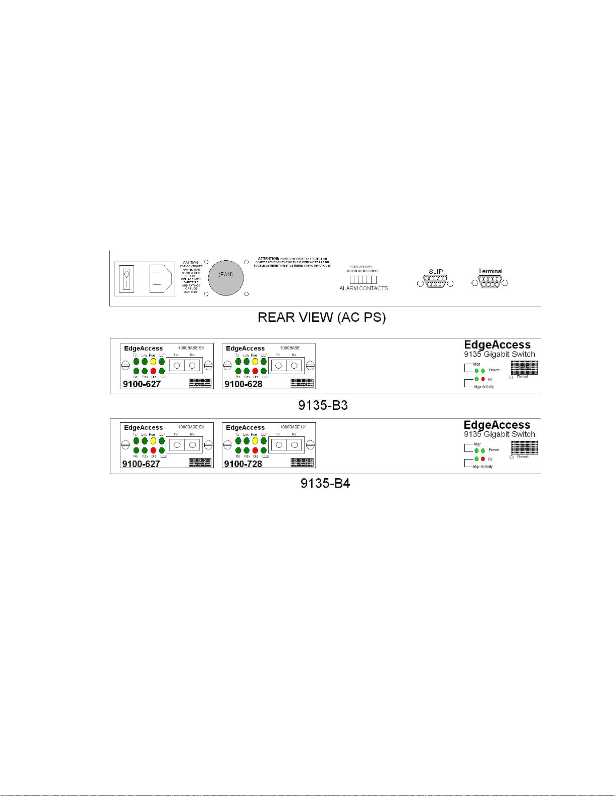
The Canoga Perkins EdgeAccess 9135G is an SNMP Managed, two-port Gigabit Ethernet Switch that
provides Managers and Network Analysts with a modular-managed 1Gbps LAN platform. The
9135G incorporates two modular 1 GBps interface modules. Both interface modules are hotswappable, plug-in, Duplex-SC interface modules with these options:
• 850nm multimode
• 1000Base-LX 1310nm singlemode
• 1000Base-LD 1310nm, 1550nm singlemode
Additionally, the 9135G supports IEEE 802.1d and 802.1Q standards.
LD
Figure 1. 9135G SNMP Managed Gigabit Ethernet Switch
1.1 Features
The 9135G includes these features:
• Plug-in, hot-swappable 1GBps multimode and single mode interface modules
• Supports IEEE 802.1d bridging specifications
• Supports IEEE 802.1Q 1522 byte tagged packets
• Store and forward operation
• Supports full- and half-duplex data transfer
• Non-blocking switch
• Full wire speed
• Supports spanning tree algorithm
Model 9135G SNMP Managed Gigabit Ethernet Switch
1-1

EdgeAccess Ethernet Switch
• Address table supports 1,000 entries
• Alarm relay contacts connector per port link status
Management Features:
• Intel i960-RP CPU
• 33MHz
• PCI interface
• 512KB BOOT ROM
• 4MB flash memory
• 8MB DRAM
• SNMP
• Hardware and software watchdog for automatic recovery
• Terminal Interface - Serial EIA-232 Port for terminal configurations (DE-9 female DTE)
• SLIP Interface - Serial EIA-232 Port for remote management and monitoring (DE-9 male DCE)
1-2
Model 9135G SNMP Managed Gigabit Ethernet Switch

EdgeAccess Ethernet Switch
Chapter 2 Setup and Installation
This section describes how to install and operate the 9135G. The 9135G can be installed in these
ways:
• Standard 19-inch relay rack
• 23-inch relay rack (use the optional RM-1U-23 Kit)
• Wall mounted
• Standalone unit
2.1 Unpacking the 9135G
The 9135G is tested and inspected prior to shipment from the factory. If there is obvious damage to
the shipping container, contact the carrier immediately.
It is recommended that you keep the shipping container until the unit has been installed and verified
as being fully operational. In the unlikely event that the unit is defective, contact the Canoga Perkins
Customer Service Department for a return authorization number (RMA) and for instructions on return
shipment. Refer to Appendix A, Warranty, for further details.
Caution! Follow proper electrostatic discharge (ESD) safety precautions when handling Canoga
Perkins products, as with all electronic devices with static sensitive components.
2.2 Mounting the 9135G
The 9135G can be used in three mounting configurations; rack mounted, wall mounted and
standalone.
2.2.1 Rack Mounting
The rackmount kit contains rack mounting ears and six mounting screws to install the 9135G in a
standard 19-inch relay rack or, with the optional RM-1U-23 kit, a 23-inch relay rack.
The 9135 includes two sets of mounting screw holes on each side:
• Front Chassis Mount: Align the rack mounting ears flush with the front panel so that the three
bracket holes align with the screw holes on the side panel of the 9135G. Insert the screws and
tighten hand tight.
• Mid Chassis and Recessed Chassis Mount: Align the rack mounting ears so that the three bracket
holes align with the screw holes on the side panel of the 9135G. Insert the screws and tighten
hand tight.
Model 9135G SNMP Managed Gigabit Ethernet Switch
2-1
EdgeAccess Ethernet Switch
2.2.2 Standalone
When using the 9135G as a standalone unit, place it on a secure, flat surface.
Ensure that the 9135G is within reach of these connections:
• Power outlet
• Fiber optic connections
2.3 Power-up
The 9135G can be equipped with either an AC or a DC power entry module.
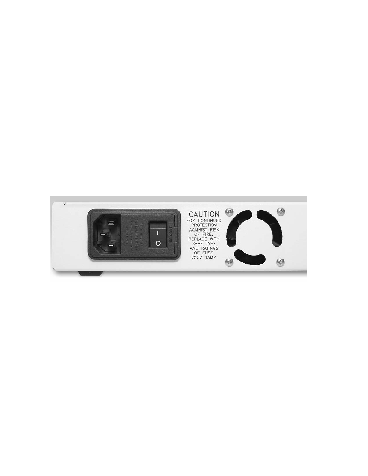
2.3.1 AC Power Entry and Switch
The power entry module, which includes the ON/Off switch, is located next to the fan assembly on
the rear panel as shown in Figure 2.
2-2
Figure 2. Power Entry Module with AC Power Switch
Model 9135G SNMP Managed Gigabit Ethernet Switch
EdgeAccess Ethernet Switch
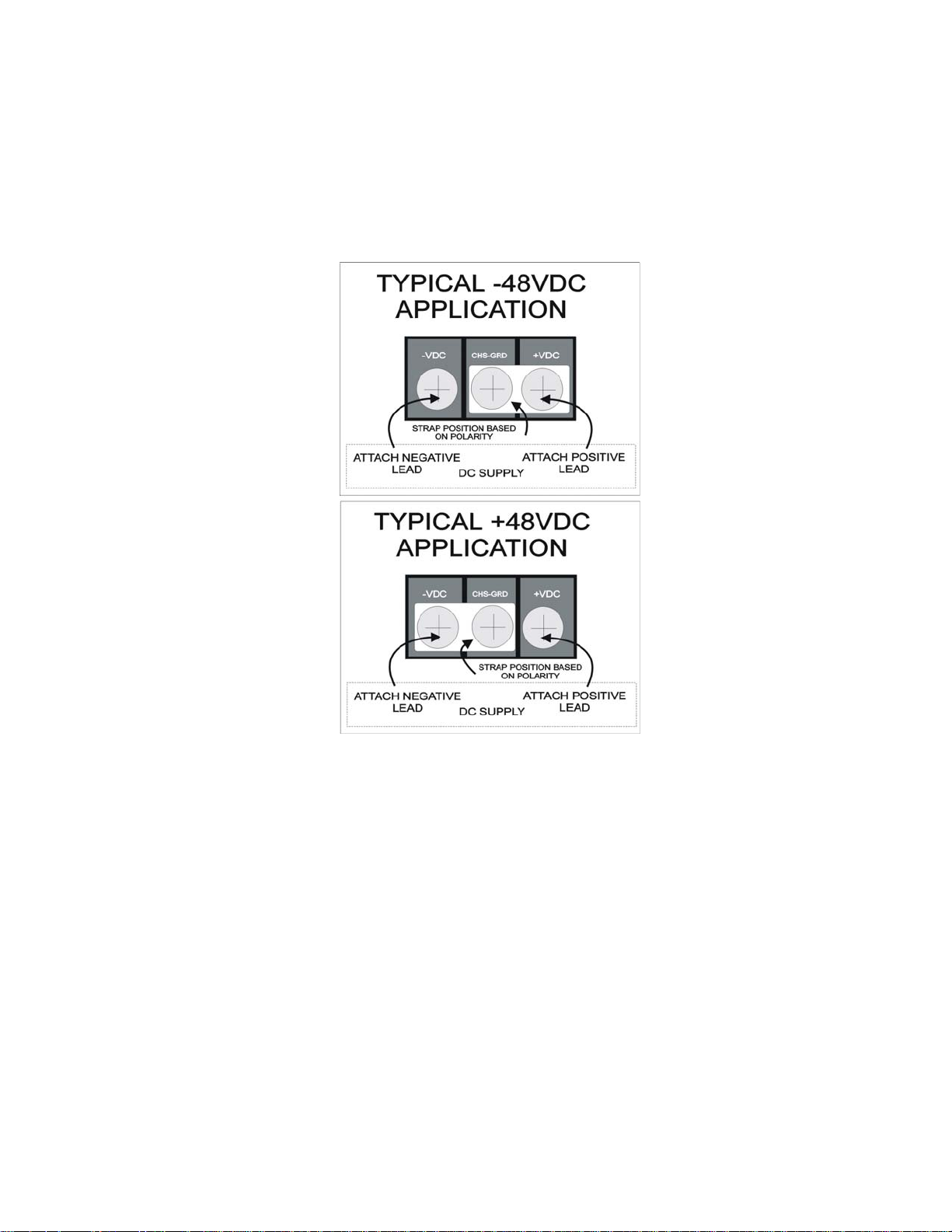
2.3.2 DC Power Entry
The connection for the -48VDC power supply is detailed in Figure 3.
-VDC Terminal for negative lead
CHS-GND Chassis ground terminal for DC supply
+VDC Terminal for positive lead
Figure 3. Typical DC Power Supply Connections
The polarity of the source DC supply determines the position of the grounding strap on the 9135G
DC terminal strip.
For a -48VDC supply, connect the grounding strap between the Chassis Ground and the +VDC
terminal. Connect the positive (+), or Common, lead from the source DC supply to the +VDC
terminal, and connect the negative (-) lead from the source DC supply to the -VDC terminal.
For a +48VDC supply, connect the grounding strap between the Chassis Ground and the -VDC
terminal. Connect the negative (-), or Common lead, from the source DC supply to the -VDC
terminal, and connect the positive (+) lead from the source DC supply to the +VDC terminal.
Reversing the connections may cause damage to both the DC source and the DC converter module in
the 9135G.
Model 9135G SNMP Managed Gigabit Ethernet Switch
2-3
EdgeAccess Ethernet Switch
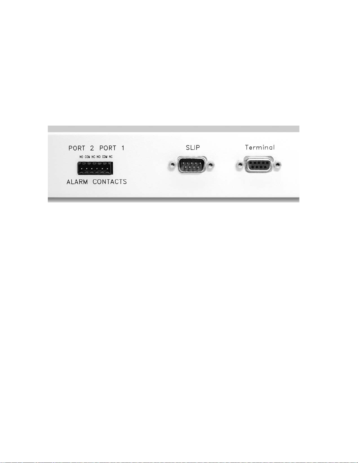
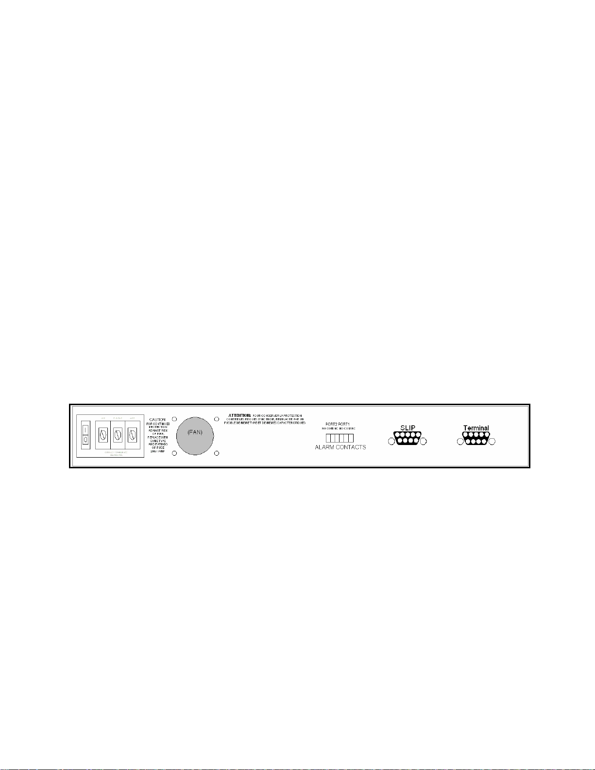
2.4 Relay Contacts
The alarm contacts for the 9135G are located next to the SLIP Port on the rear panel and are shown in
Figure 6. These contacts monitor fault conditions for each port.
• Loss of link integrity
• Remote Fault signaling
• Unit power fail
Figure 4. Relay Contacts on Rear Panel
Note: The alarm relay contacts located on the rear of the 9135G can be connected to either open or
close a circuit, allowing current to flow to an alarm or alert system by the presence or absence of
power.
The relay alarm contacts are shown in Figure 4:
• NO The relay is open during normal operation and closed during a fault condition.
• COM The common pin between alarm contacts.
• NC The relay is closed during normal operation and open during a fault condition.
2.5 Installing Modules
Insert the Module into the slot. Push firmly on the center of the front panel. If you encounter
resistance, stop, pull the interface out, and attempt to reinsert it. If you still encounter resistance, pull
the interface completely out and inspect both the interface guide and the interface. When the module
is firmly seated, tighten both screws on the front panel.
2.6 Cabling
Cables for the 9135G include the management cables to the SLIP and Terminal ports and the fiber
optic link from the local port to the remote port.
2-4
Model 9135G SNMP Managed Gigabit Ethernet Switch
EdgeAccess Ethernet Switch
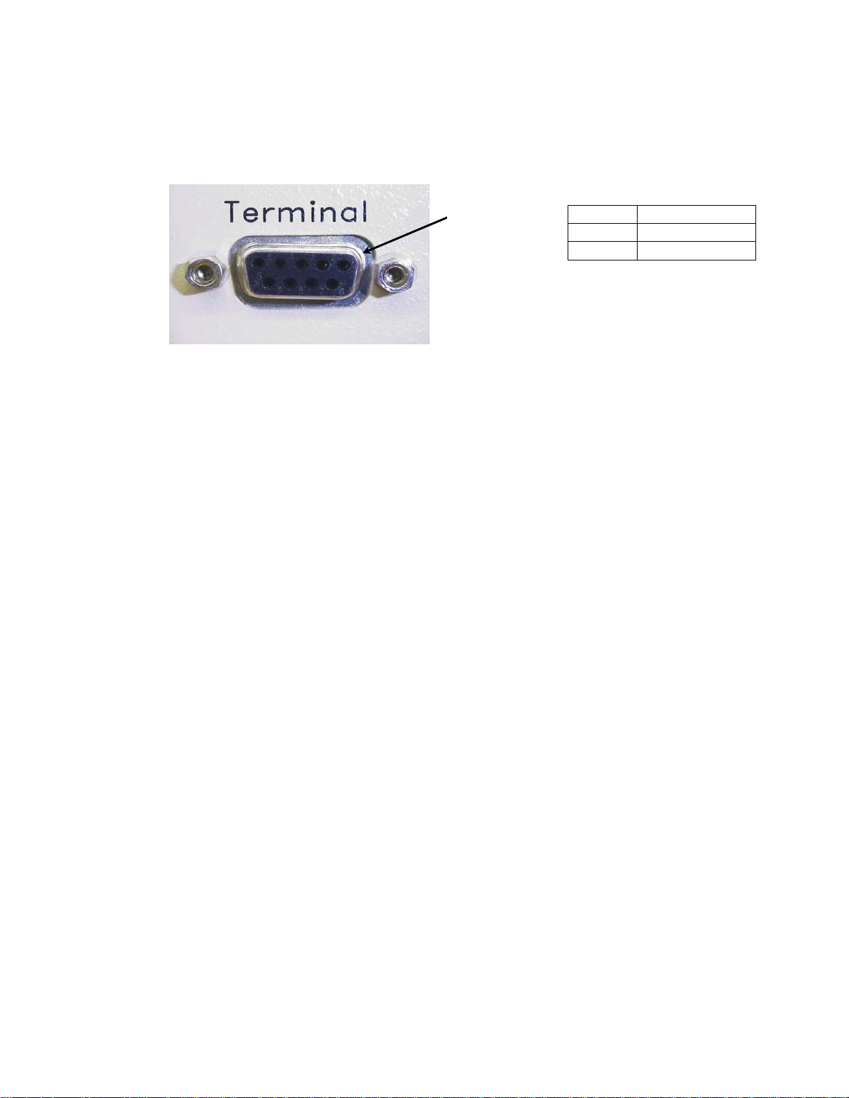
2.6.1 Management Access --Terminal
The Terminal Port (EIA 232), located on the rear panel of the 9135G, provides access to the User
Interface Management Program.
Pin 1
Figure 5. VT100 Management Connection - Terminal
Pin 2 TxD Output
Pin 3 RxD Input
Pin 5 SIG GND
Model 9135G SNMP Managed Gigabit Ethernet Switch
2-5
EdgeAccess Ethernet Switch
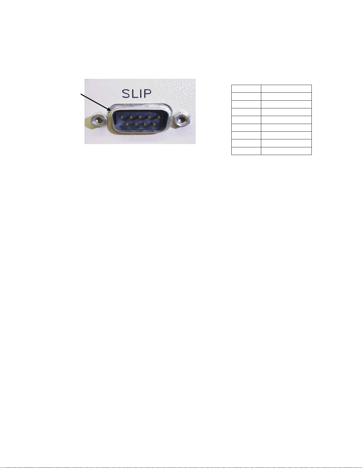
2.6.2 Management Access - Modem SLIP Connection
The SLIP Port, located on the rear panel of the 9135G, provides a modem connection to access the
management program.
Pin 1
Figure 6. Modem SLIP Management Connection - SLIP
Pin 1 DCD Input
Pin 2 RxD Input
Pin 3 TxD Output
Pin 4 DTR Output
Pin 5 SIG GND
Pin 6 DSR Input
Pin 7 RTS Output
Pin 8 CTS Input
Pin 9 Not Used
2.6.3 Fiber Optic Cabling
Connect all optical cables using Tx to Rx, and Rx to Tx orientation. Labeling each connector is highly
recommended. Keep optical connectors lint and dust free, clean, and protected when not in use.
Connecting Fiber Optic Cables
Dirty fiber connectors are a common source of attenuation, especially for single mode fiber. Keep the
connectors clean at all times and install the dust covers when not in use. Whenever there is a
significant, unexplained light loss, first clean the connectors. Use extreme care when removing or
installing connectors to avoid damaging the fiber end-face surface or the connector housing.
Caution! Clean the Fiber Connectors before connecting them. Dirt contaminates both the fiber
coupler and the fiber receptacle, and can cause a significant light signal loss.
Before installing any type of fiber cable or connector, use a lint-free alcohol pad from a fiber cleaning
kit to clean the ferrule and the end-face surface of the fiber coupler.
Use extreme care when installing or removing connectors to avoid damaging the fiber end-face
surface or the connector housing.
2-6
Model 9135G SNMP Managed Gigabit Ethernet Switch
EdgeAccess Ethernet Switch
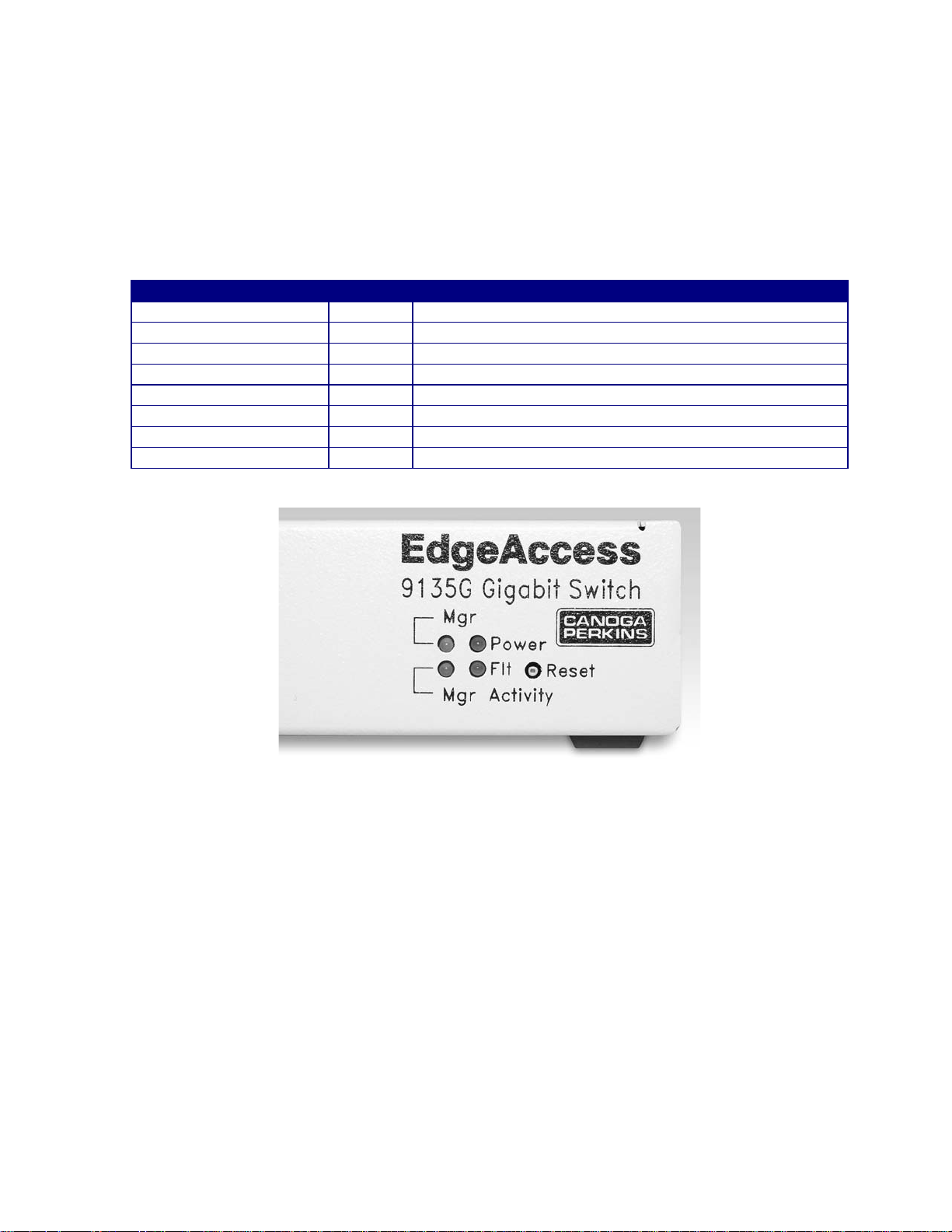
2.7 LED Indicators
The 9135G incorporates four LED indicators. The interface modules incorporate eight LED
indicators.
2.7.1 9135G LEDs
Table 1. 9135G LEDs
LED Status Description
Mgr (Manager) Off Management is not functioning properly
Green Management is functioning properly
Power Off 9135G input power is not at an acceptable level
Green 9135G input power is good
Flt (Fault) Off The 9135G has no fault conditions
Red Indicates a self-test failure
Mgr Activity Off There is no management activity
Green There is management activity
Figure 7. 9135G LED Indicators
Model 9135G SNMP Managed Gigabit Ethernet Switch
2-7

EdgeAccess Ethernet Switch
2.7.2 9135G Interface LEDs
Table 2. 9135G Interface LEDs
LED Status Description
Tx (Transmit) Off No transmit activity
Green Currrent transmit activity
Red Transmitter is disabled due to LLF or LLE
Lnk (Link) Off The interface has not established an optical link
Green The interface has an optical link established
Pse (Pause) Amber The interface is receiving too much data or too fast
LLF (Link Loss Forward) Off Link Loss Forward is disabled
Green Link Loss Forward is enabled
Rx Off No receive activity
Green Current receive activity
Red Remote fault detected
Fdx Off Operating as half-duplex
Green Operating as full-duplex
Dis (Disable) Off Modular interface enabled
LLE (Link Loss Echo) Off Link Loss Echo is disabled
Green Link Loss Echo is enabled
Figure 8. 9135G Interface LED Indicators
2.7.3 Enable/Disable LLF or LLE
You can select LLF and LLE or Remote Fault sensing in the hardware or software by specifying
hardware or software control for these functions in the user interface. For details on the user
interface, see Section 3.2.3, Port Information. LLF is limited to only one port at a time. To set these
functions on an interface module:
Step 1. Loosen the captive screws and pull the module out of the chassis.
Step 2. Locate SW1, then set it as needed:
• Switch position 1 controls LLF: On enables LLF; Off disables LLF
• Switch position 2 selects LLE or Remote Fault: On selects LLE; Off selects Remote Fault
Step 3. Insert the module in the chassis and tighten the captive screws.
2-8
Model 9135G SNMP Managed Gigabit Ethernet Switch
EdgeAccess Ethernet Switch
Chapter 3 Management
Configure the 9135G management program for the environment where it will be used (IP address,
Gateway address, and Subnet mask that will be assigned to the unit). There are seven methods that
can be used to access the management program, two of which come with Windows 95/98 and NT:
HyperTerminal and Telnet. Before using Telnet, you must use HyperTerminal for access and set up
Telnet for the IP address in the Host Table/SNMP Settings screen.
• Terminal (HyperTerminal or similar program)
• Telnet - Inband
• Telnet - SLIP
• SNMP - Inband (network management program)
• SNMP - SLIP (network management program)
• SLIP - Dialup
• SLIP - direct connect
3.1 Setup and Configuration of the Serial Port
To set up the serial port and access the terminal program for the first time, use a terminal port
connection and HyperTerminal or a similar program (must have serial port connection on a PC).
• Locate the SLIP and Terminal Port on the rear panel of the 9135G, as shown in Figure 9. Near the
connectors, you will see a label with the MAC (Media Access Control) address. This address is
unique to the unit, so make note of it for future reference.
Figure 9. SLIP and Terminal SNMP Management Connectors
• Using a straight through serial cable with DE-9 male and female connectors, insert the male end
into the connector marked "Terminal." Connect the DE-9 female end to the male serial interface
on the back of your PC (usually COM1).
Note: Laptops typically have a DE-9 male connector; desktop PCs may differ.
3.1.1 PC Configuration for Terminal Operation
The following explanation assumes Windows 95/98™ is installed and operational. Windows NT
screens will differ slightly.
• Power up your PC. When the main Windows screen appears, click Start.
Model 9135G SNMP Managed Gigabit Ethernet Switch
3-1
EdgeAccess Ethernet Switch
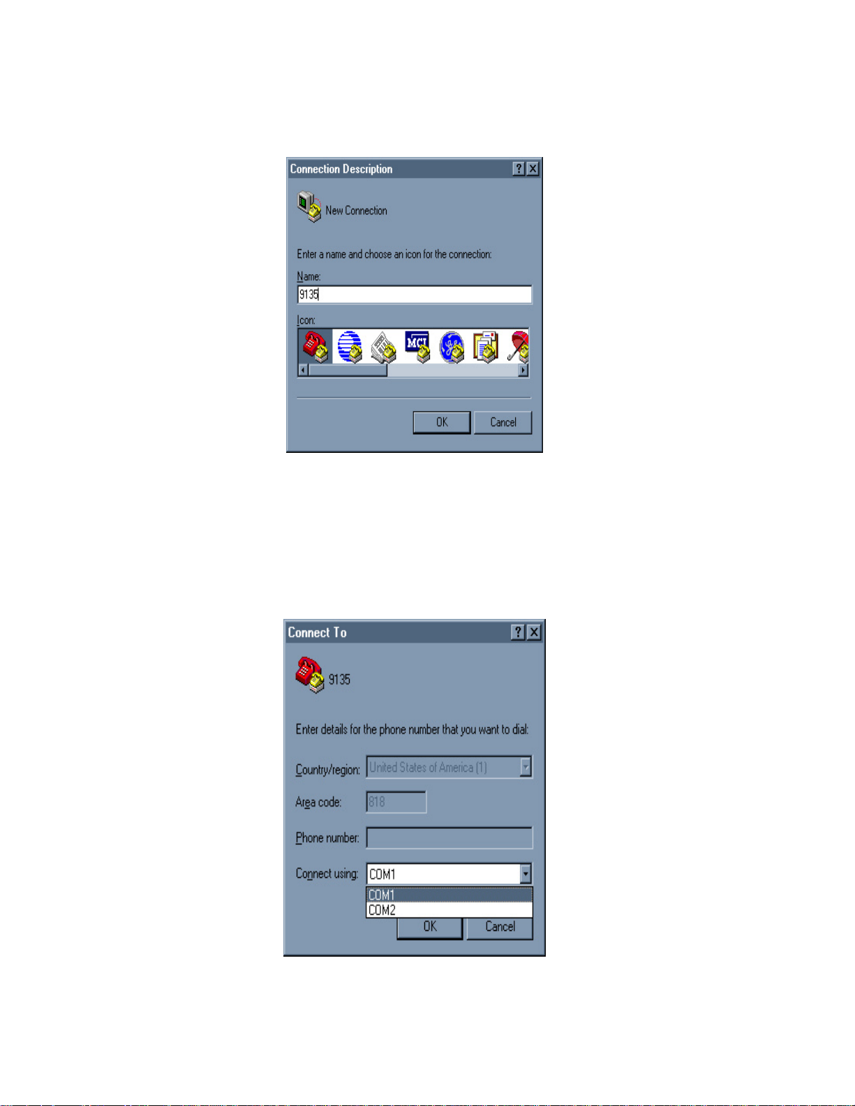
• Highlight Programs, then Accessories, then the HyperTerminal folder, and click on
HyperTerminal. The Connection Description window appears. See Figure 10.
Figure 10. HyperTerminal New Connection
• The HyperTerminal program opens and prompts you to name the connection for terminal
operation, as shown in Figure 10. Choose an icon and a name for the terminal connection file and
click OK. The Connect To window appears.
• From the Connect using drop down menu, select COM1 and Click OK. See Figure 11.
3-2
Figure 11. COM Port Connection
Model 9135G SNMP Managed Gigabit Ethernet Switch
EdgeAccess Ethernet Switch
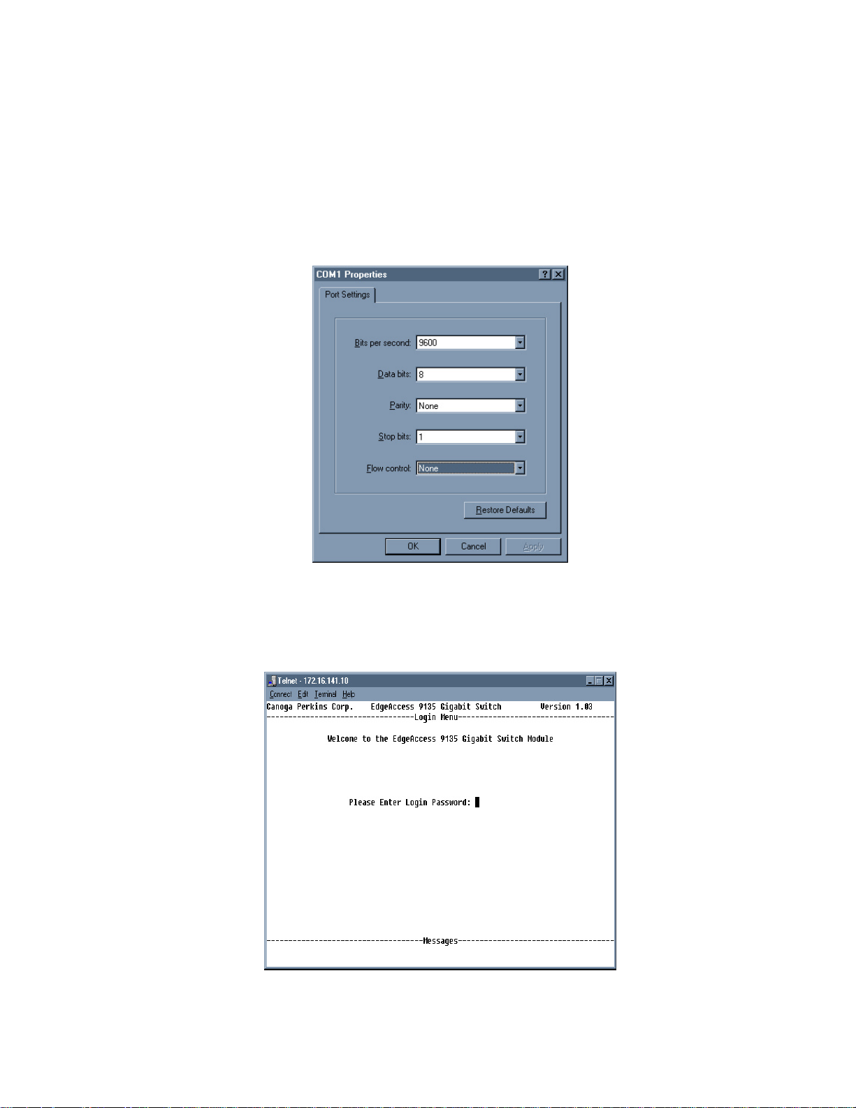
• Enter the COM Port parameters as shown in Figure 12.
• Bits per second: 9600
• Data bits: 8
• Parity: None
• Stop bits: 1
• Flow control: None
Figure 12. COM Port Properties
• HyperTerminal opens the 9135G Gigabit Management program. See Figure 13. Telnet can also
be used from the DOS Command Prompt: enter telnet, a space, and the IP Address.
Figure 13. The 9135G Login Menu
Model 9135G SNMP Managed Gigabit Ethernet Switch
3-3
EdgeAccess Ethernet Switch
3.2 Operation of the 9135G Management Program
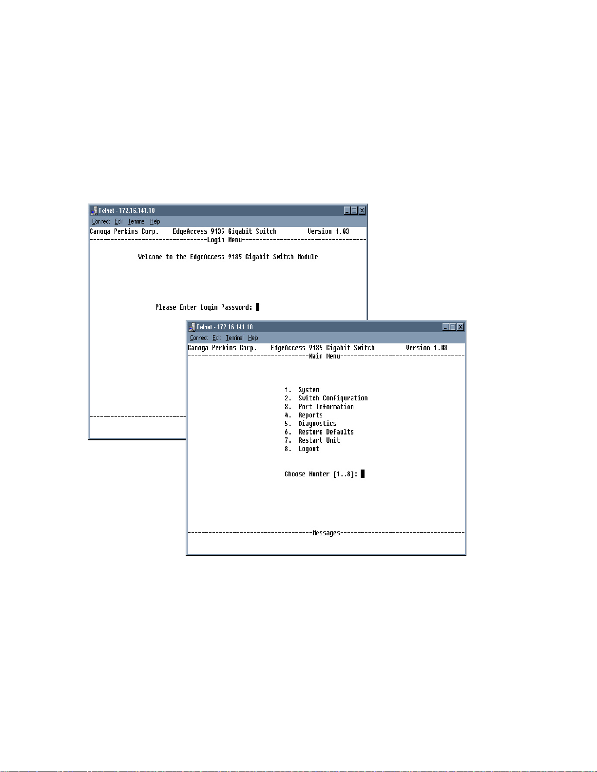
The first screen that will come up will be the Login Menu. If this is your initial setup and no password
has been set, press <Enter> instead of a password. If a password has been set, enter the password for
Supervisor, Manager, or User, and press <Enter>. The Main Menu screen appears. See Figure 14.
Note: Take care when setting the passwords. Each editable menu item has a minimum access level
that must be met in order to edit it. For example, if you are logged in as USER and try to change a
Spanning Tree parameter, you will see "ACCESS DENIED: SUPERVISOR LEVEL REQUIRED".
Refer to section 3.2.1.4, Passwords.
Figure 14. Main Menu
Note: The 9135G Management Program will automatically log the user out after 10 minutes of
inactivity.
3-4
Model 9135G SNMP Managed Gigabit Ethernet Switch
 Loading...