

CANOGA PERKINS 9120 User Manual
Model 9120
Gigabit Ethernet Media
Converter
User Manual

Canoga Perkins
CAUTION!
This product may contain a laser diode operating at a wavelength of 1300nm - 1600nm. Use of
optical instruments (e.g., collimating optics) with this product may increase eye hazard. Use of
controls or adjustments, or performing procedures other than those specified herein may result in
hazardous radiation exposure.
Under normal conditions, the radiation levels emitted by this product are under Class 1 limits in 21
CFR Chapter 1, Subchapter J.
ATTENCION!
Cet équipement peut avoir une diode laser émettant à des longueurs d'onde allant de 1300nm à
1600nm. L'utilisation d'instruments optiques (par exemple : un collimateur optique) avec cet
équipement peut s'avèrer dangereuse pour les yeux. Procéder à des contrôles, des ajustements ou toute
procédure autre que celles décrites ci-après peut provoquer une exposition dangereuse à des
radiations.
Sous des conditions normales, le niveau des radiations émises par cet équipement est en dessous des
limites prescrites dans CFR21, chapitre 1, sous chapitre J.
NOTICE!
This device contains static sensitive components. It should be handled only with proper ElectroStatic
Discharge (ESD) grounding procedures.
NOTE!
Cet équipement contient des composants sensibles aux décharges électro-statiques. Il doit absolument
être manipulé en respectant les règles de mise à la terre afin de prévenir de telles décharges.
ii
9120 Gigabit Ethernet Media Converter

Canoga Perkins
NOTICE
Canoga Perkins has prepared this users manual for use by customers and Canoga Perkins personnel as
a guide for the proper installation, operation and/or maintenance of Canoga Perkins equipment. The
drawings, specifications and information contained in this document are the property of Canoga
Perkins and any unauthorized use or disclosure of such drawings, specifications and information is
prohibited.
Canoga Perkins reserves the right to change or update the contents of this manual and to change the
specifications of its products at any time without prior notification. Every effort has been made to
keep the information in this document current and accurate as of the date of publication or revision.
However, no guarantee is given or implied that the document is error free or that is accurate with
regard to any specification.
Canoga Perkins Corporation
20600 Prairie Street
Chatsworth, California 91311-6008
Business Phone: (818) 718-6300
(Monday - Friday 7 a.m. - 5 p.m. Pacific Time)
FAX: (818) 718-6312 (24hrs.)
Web Site: www.canoga.com
Email: fiber@canoga.com
Copyright© 2001 - 2005 Canoga Perkins Corporation
All Rights Reserved
Model 9120 Gigabit Media Converter
User Manual
Product Number 6911750
Rev. H 09/2005
To reference Technical Advisories and Product Release Notes, go to Canoga Perkins'
website: http://www.canoga.com/cservice.htm
9120 Gigabit Ethernet Media Converter
iii

Canoga Perkins
Table of Contents
Chapter 1 Overview.................................................................................................. 1-1
1.1 Ship List .................................................................................................................................. 1-2
1.2 Applications ............................................................................................................................1-2
Chapter 2 Setup and Installation ............................................................................2-1
2.1 Unpacking ............................................................................................................................... 2-1
2.2 Setup of the 9120 Media Converter ........................................................................................2-1
2.2.1 User Port Connection .............................................................................................................2-1
2.2.2 Extension Port Connection.....................................................................................................2-2
2.2.3 Four-Position DIP Switch ......................................................................................................2-2
2.3 Installing the 9120 Media Converter....................................................................................... 2-3
2.3.1 Standalone Unit......................................................................................................................2-3
2.3.2 Rackmount Installation ..........................................................................................................2-3
2.3.3 Configuring the Fault/Forwarding DIP Switch......................................................................2-4
Chapter 3 Operation.................................................................................................3-1
3.1 LED Indicators ........................................................................................................................3-1
3.2.1 Canoga Remote Fault.............................................................................................................3-2
3.2.2 Link Loss Forwarding - User to Extension ............................................................................3-3
3.2.3 Link Loss Forwarding - Extension to User ............................................................................3-4
3.2.4 Link Loss Echo ......................................................................................................................3-5
3.3 Models and Product Description .............................................................................................3-7
Chapter 4 Troubleshooting ......................................................................................4-1
Chapter 5 Technical Specifications .........................................................................5-1
5.1 Gigabit Multimode (MM) 850nm (SX)...................................................................................5-1
5.2 Gigabit Single Mode (SM) 1310nm LX..................................................................................5-1
5.3 Gigabit Single Mode (SM) 1310nm LD (DFB) ......................................................................5-2
5.4 Gigabit Single Mode (SM) 1550nm EX (DFB) ......................................................................5-2
5.5 Functional................................................................................................................................ 5-3
5.6 Power.......................................................................................................................................5-3
5.7 Physical / Environmental ........................................................................................................5-3
Chapter 6 Glossary ...................................................................................................6-1
Appendix A ...............................................................................................................A-1
iv
9120 Gigabit Ethernet Media Converter

Canoga Perkins
List of Figures
Figure 1. 9120 Categories................................................................................................................. 1-1
Figure 2. Typical 9120 Application................................................................................................... 1-2
Figure 3. 9120 Extended Application. ............................................................................................... 1-3
Figure 4. Front View of the 9120. ..................................................................................................... 2-1
Figure 5. User Port............................................................................................................................ 2-2
Figure 6. Extension Port.................................................................................................................... 2-2
Figure 7. Four Position DIP Switch.................................................................................................. 2-2
Figure 9. 9101 LAN Chassis with 9120's. ......................................................................................... 2-3
Figure 10. Fault Forwarding DIP Switch. ........................................................................................2-4
Figure 11. LED Indicators. ............................................................................................................... 3-1
Figure 12. Remote Fault Diagram. ................................................................................................... 3-2
Figure 13. Link Loss Forwarding - User to Extension...................................................................... 3-3
Figure 14. Link Loss Forwarding - Extension to User...................................................................... 3-4
Figure 15. Link Loss Echo Switch Position....................................................................................... 3-5
Figure 16. Link Loss Enable fault with 9120 to 9120 Link. .............................................................. 3-5
Figure 17. Link Loss Enable fault with 9120 to Customer Premise Link.......................................... 3-6
List of Tables
Table 1. LED Descriptions. ............................................................................................................... 3-1
9120 Gigabit Ethernet Media Converter
v

Canoga Perkins
This page is intentionally left blank.
vi
9120 Gigabit Ethernet Media Converter
Canoga Perkins
Chapter 1
Overview
The 9120 is a Gigabit Ethernet Media Converter. It extends multi mode Gigabit segments up to 70km
over single mode fiber. It is designed for installation into the Canoga Perkins 9101 Chassis and is also
available as a standalone unit. The unit is especially suited for the long-distance extension of Gigabit
LAN segments. Extension port options include 1310nm on multimode or single mode fiber and
1550nm on singlemode fiber.
The 9120 introduces Gigabit extension capability to Canoga Perkins 9101 chassis. It is field
installable and can coexist with Canoga Perkins 8829 10Mbps, and 9119 100Mbps Ethernet
converters. The 9120 is a NEBS Level 3 compliant (in chassis) product designed and built with
quality components to ensure reliability and longevity.
The 9120 features user controllable Link Loss Forwarding (LLF), Canoga Remote Fault (RMTF), and
Link Loss Echo (LLE). The user may enable or disable these features from a set of easily accessed
switches located on the front panel of the 9120. Primary application is the interconnection of gigabit
Enterprise Switches and Service Provider Backbone Networks. Within the 9101 platform, the 9120
addresses the Service Providers' requirements for Transparent LAN Services across a widely
dispersed customer environment and physical plant.
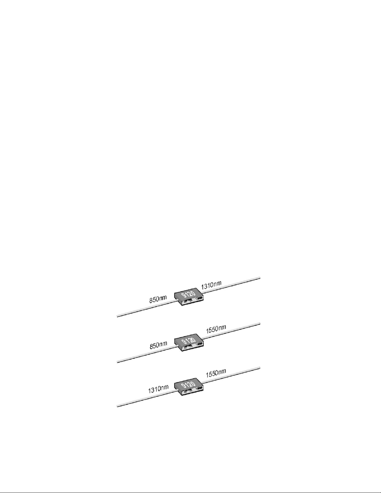
The 9120 Media Converter is available in three categories:
• Gigabit Ethernet 850nm MM SC
• Gigabit Ethernet 1310nm SM SC
• Gigabit Ethernet 1550nm SM SC
Figure 1. 9120 Categories.
9120 Gigabit Ethernet Media Converter
1-1

Canoga Perkins
9120 Media Converter Feature List:
• Full-duplex 1000Mbps Ethernet operation up to 70km
• Multimode and single mode fiber support
• Supports 850nm, 1310nm and 1550nm
• Field installable into existing 9101 Chassis
• Available as standalone or rackmount for EdgeAccess 9101Chassis
• Front panel LEDs for diagnostics and monitoring
• Link Loss Forwarding, Canoga Remote Fault, and Link Loss Echo Alarms
• User Configurable Link Loss Forwarding, Canoga Remote Fault, and Link Loss Echo
• NEBS Level 3 compliant (in the 9101 Chassis)
1.1 Ship List
The following items are included:
• 9120 Media Converter
• User Manual
• Power Supply with 6-foot power cord (standalone model only)
• Tie Wrap/Velcro Kit
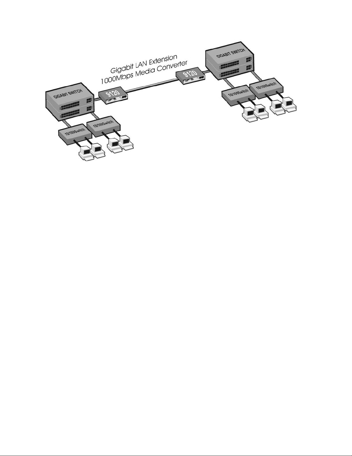
1.2 Applications
Figure 2 shows a typical application allowing a full-duplex link at a distance of up to 70km.
Figure 2. Typical 9120 Application.
1-2
9120 Gigabit Ethernet Media Converter
Canoga Perkins
Figure 3. 9120 Extended Application.
9120 Gigabit Ethernet Media Converter
1-3

Canoga Perkins
This page is intentionally left blank.
1-4
9120 Gigabit Ethernet Media Converter
 Loading...