

CANOGA PERKINS 9101 LAN User Manual

Canoga Perkins
Model 9101
LAN Chassis
LAN Chassis


NOTICE
Canoga Perkins reserves the right to change or update the contents of this manual
and to change the specifications of its products at any time without prior notification. Every effort has been made to keep the information in this document current
and accurate as of the date of publication or revision. However, no guarantee is
given or implied that the document is error free or that it is accurate with regard to
any specification.
Canoga Perkins has prepared this manual for use by customers and Canoga
Perkins personnel as a guide for the proper installation, operation and/or maintenance of Canoga Perkins equipment. The drawings, specifications and information
contained in this document are the property of Canoga Perkins and any unauthorized use or disclosure of such drawings, specifications and information is prohibited.
Canoga Perkins Corporation
20600 Prairie Street
Chatsworth, CA 91311-6008
(818) 718-6300
FAX: (818) 718-6312
Web Site: http://www.canoga.com
email: fiber@canoga.com
Copyright 1999 - 2005 Canoga Perkins
All Rights Reserved
9101 LAN Chassis
User Manual
Part Number 6911570
Rev. J 09/2005
To reference Technical Advisories and Product Release Notes, go to Canoga
Perkins’ website: http://www.canoga.com/cservice.htm
Canoga Perkins Model 9101 LAN Chassis
supports 10Mbps, 100Mbps Media Converters, and WA-2 Passive WDM

9101 LAN Chassis Canoga Perkins
Table of Contents
Chapter 1 - Overview ........................................... 7
1.1 9101 LAN Chassis Application .................................... 8
1.2 Packing List ..................................................................8
Chapter 2 - Chassis Installation ........................... 9
2.1 9101-0 LAN Chassis .....................................................9
2.2 9101-1, 2, 3 or 4, LAN Chassis ................................... 10
Chapter 3 - Module Installation ......................... 13
3.1 8814 Fiber Optic Transceiver ...................................13
3.2 Media Converters (Models 8829, 9119) ...................15
3.3 Connection to Alarm Contacts ..................................18
3.4 Connection to DC Power Supply ...............................19
Chapter 4 - Troubleshooting............................... 21
4.1 Mechanical ..................................................................21
4.2 Electrical.....................................................................21
4.2.1 Power Supply (P/S) Replacement......................................... 22
Chapter 5 - Specifications .................................. 27
5.1 9101-0 LAN Chassis.................................................. 27
5.2 9101-1, 2, 3 or 4, LAN Chassis ................................... 27
5.2.1 Power Requirement:.............................................................. 27
5.2.2 Physical / Environmental: ...................................................... 28
5.2.3 Certification/Compliance ....................................................... 28
Appendix A - Warranty ....................................... 29
5

Canoga Perkins 9101 LAN Chassis
List of Figures
1-1 9101 LAN Chassis (Front View) ............................................ 7
1-2 9101 LAN Chassis Application ................................................ 8
2-1 9101-0 LAN Chassis ............................................................. 9
2-2 DC Power Connector Configuration ...................................... 10
2-3 Power Supply Cables in 9101-1, 2, 3 or 4 LAN Chassis ...... 11
3-1 8814 Fiber Optic Transceiver and Cable Connections ............ 13
3-2 Cable-Attached 8814 Fiber Optic Transceiver ....................... 14
3-3 Power Cable Connection on Media Converter ....................... 15
3-4 Fiber Optic Cable Connections on Media Converter ............. 16
3-5 Cable-Attached Media Converters ........................................ 16
3-6 100BASE-T Cable Connection on 9119 Media Converter ..... 17
3-7 9101 LAN Chassis (Rear View) ............................................ 18
3-8 9101 LAN Chassis Alarm Contacts ....................................... 19
3-9 Typical DC Power Supply Connectnions ................................ 20
4-1 Replace Power Supply - Step 1 ............................................. 23
4-2 Replace Power Supply - Step 2 ............................................. 24
4-3 Replace Power Supply - Step 3 ............................................. 25
4-4 Replace Power Supply - Step 4 ............................................. 25
4-5 Replace Power Supply - Step 5 ............................................. 26
6
9101 LAN Chassis Canoga Perkins
Chapter 1 - Overview
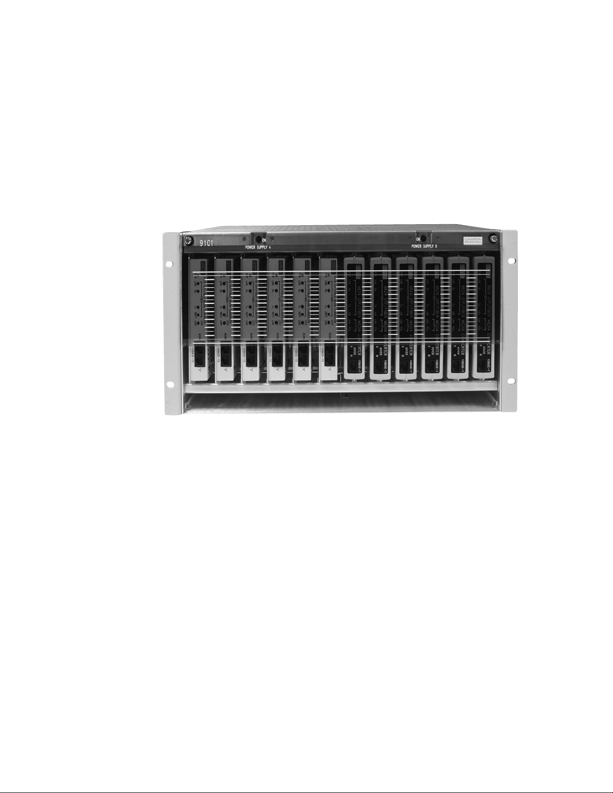
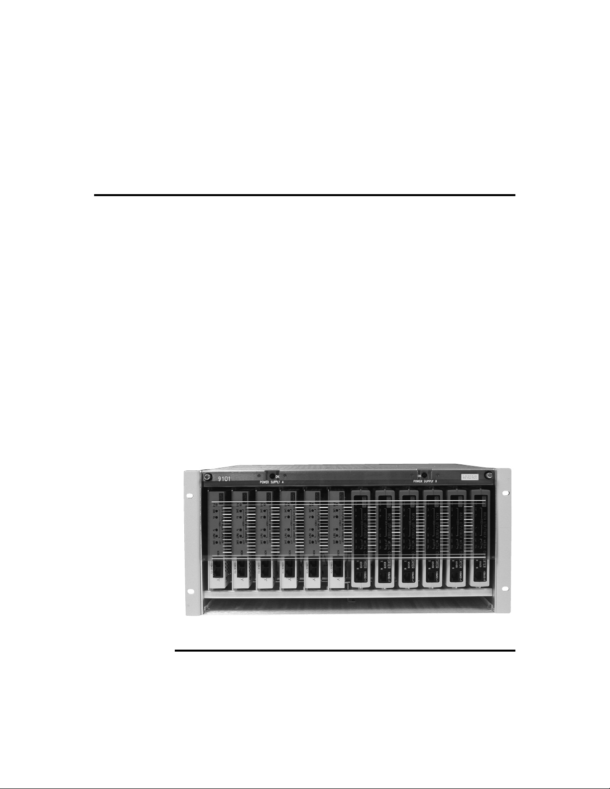
The 9101 LAN Chassis is designed to house any mix of up to twelve 8814s, 8829s,
9119s, and WA-2s (see Figure 1-1). Depending on the customer power requirements, the chassis can be ordered in one of five configuration options:
• 9101-0 (no power supplies)
• 9101-1 (120/240VAC power supply)
• 9101-2 (redundant, hot-swappable 120/240VAC power supplies)
• 9101-3 (+/-48VDC power supply)
• 9101-4 (redundant, hot-swappable +/-48VDC power supplies)
• 9101-5 (Redundant 120/240VAC and +/- 48VDC, hot swappable, load sharing
power supplies)
NOTE: All power supplies are factory configured and installed.
The 9101 LAN Chassis fits into a standard 19-inch relay rack (optional RM-5U-23
Extender Bracket for 23-inch relay racks). The integral cable tray and cable guides
make multiple unit installations quick and easy.
The 9101 LAN Chassis User Manual is designed to take you confidently from the
installation stage to the operational stage.
Figure 1-1
9101 LAN Chassis (Front View)
7
Canoga Perkins 9101 LAN Chassis
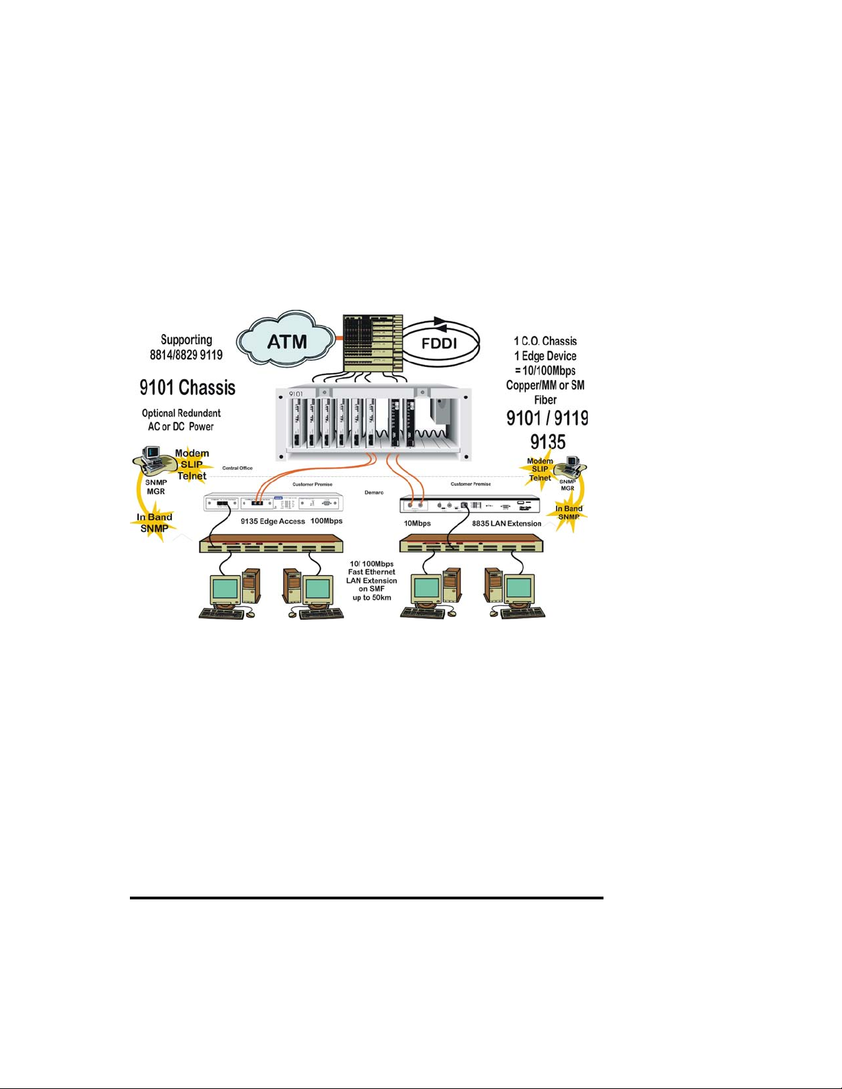
1.1 9101 LAN Chassis Application
Figure 1-2 shows a typical application utilizing the elements of the 8800-series
10Mbps and 9100-series Fast Ethernet devices.
Figure 1-2
9101 LAN Chassis Application
1.2 Packing List
If the 9101 LAN Chassis is ordered with power supplies, the power supplies will be
inserted into the unit and 19-inch chassis ears will be attached, as will the front
panel.
• 1 - 9101 LAN Chassis
• 1 - User Manual
• 1 - AC power cord (two for redundant), AC-powered units only
8

9101 LAN Chassis Canoga Perkins
Chapter 2 - Chassis Installation
2.1 9101-0 LAN Chassis
The Model 9101-0 LAN Chassis is non-powered and designed to support the 8814
Fiber Optic Transceivers and the WA-2, 2-Port passive WDM module. The
transceivers receive their power from the attached DTE device via the AUI cable.
Therefore, the setup and installation of the LAN chassis is very straight forward.
Ensure you have the necessary equipment available for the setup requirements.
Setup Requirements:
1. Suitable, well-ventilated location
2. 19-inch Relay Rack
3. Canoga Perkins-supplied equipment
Setup Procedure:
Insert the 9101-0 LAN Chassis (see Figure 2-1) into the chosen location
of the relay rack and secure with screws.
Figure 2-1
9101-0 LAN Chassis
9
Canoga Perkins 9101 LAN Chassis
2.2 9101-1, 2, 3 or 4, LAN Chassis
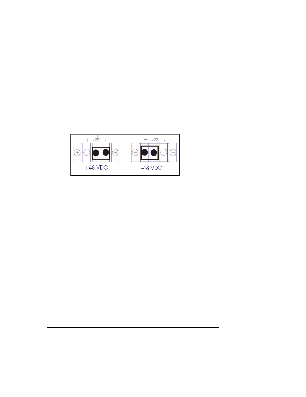
The 9101-1, 2 ,3 or 4, LAN Chassis configuration accommodates single or redundant hot-swappable, load sharing 120/240VAC or 48VDC power supplies. The
48VDC power versions can be configured as +48VDC or -48VDC: connect the earth
ground jumper from the center terminal to either -V or +V terminals respectively, on
the DC power input connector (see Figure 2-2). A power ON switch is provided for
both AC and DC versions.
* factory setting
Figure 2-2
DC Power Connector Configuration
Power indicator LEDs, one per power supply unit, are mounted on the top front
panel of the 9101 LAN Chassis and indicates the presence or absence of power
from the respective power supply. Ensure you have the necessary equipment
available for the setup requirements, as previously described.
Step 1 Note that the DC pigtail cables which supply power to the converters,
must be inserted in the chassis power distribution board for connection to
the media converters (see Figure 2-3). Refer to Section 3.2 for specific
instructions.
NOTE: The 9101 may in certain circumstances be shipped with DC pigtails
installed and tie wrapped. This tie wrap does not meet NEBS Level Three
compliance and should be removed upon installation of your 9101.
Step 2 Insert the 9101 LAN Chassis into the chosen location within the relay rack
and secure it with screws. Connect the power supply cord(s) to a power
source. Also, ensure that a socket outlet is easily accessible and located
near user equipment.
Step 3 Once a power supply is connected to the appropriate power source (AC or
48VDC) and power is turned on, verify operation of the power supply by
ensuring that the LED indicator for each respective supply is illuminated.
10
 Loading...