

CANOGA PERKINS 3240S SNMP User Manual

Model 3240S
SNMP-Managed T1/E1
Fiber-Optic Multiplexer
User Manual


NOTICE
Canoga Perkins has prepared this users manual for use by customers and Canoga Perkins personnel as
a guide for the proper installation, operation and/or maintenance of Canoga Perkins equipment. The
drawings, specifications and information contained in this document are the property of Canoga
Perkins and any unauthorized use or disclosure of such drawings, specifications and information is
prohibited.
Canoga Perkins reserves the right to change or update the contents of this manual and to change the
specifications of its products at any time without prior notification. Every effort has been made to
keep the information in this document current and accurate as of the date of publication or revision.
However, no guarantee is given or implied that the document is error free or that is accurate with
regard to any specification.
Canoga Perkins Corporation
20600 Prairie Street
Chatsworth, California 91311-6008
Business Phone: (818) 718-6300
(Monday - Friday 7 a.m. - 5 p.m. Pacific Time)
FAX: (818) 718-6312 (24 hrs.)
Web Site: www.canoga.com
Email: fiber@canoga.com
Copyright © 1999 - 2005 Canoga Perkins Corporation
All Rights Reserved
EdgeAccess
Universal Chassis System
Model 3240S
User Manual
Model Number 3240S-UM
Product Number 6910380
Rev. J 01/2008
®


CAUTION!
This product may contain a laser diode operating at a wavelength of 1300 nm - 1600 nm. Use of
optical instruments (e.g., collimating optics) with this product may increase eye hazard. Use of
controls or adjustments, or performing procedures other than those specified herein may result in
hazardous radiation exposure.
Under normal conditions, the radiation levels emitted by this product are under Class 1 limits in 21
CFR Chapter 1, Subchapter J.
ATTENCION!
Cet équipement peut avoir une diode laser émettant à des longueurs d'onde allant de 1300nm à
1600nm. L'utilisation d'instruments optiques (par exemple : un collimateur optique) avec cet
équipement peut s'avèrer dangereuse pour les yeux. Procéder à des contrôles, des ajustements ou toute
procédure autre que celles décrites ci-après peut provoquer une exposition dangereuse à des
radiations.
Sous des conditions normales, le niveau des radiations émises par cet équipement est en dessous des
limites prescrites dans CFR21, chapitre 1, sous chapitre J.
NOTICE!
This device contains static sensitive components. It should be handled only with proper ElectroStatic
Discharge (ESD) grounding procedures.
NOTE!
Cet équipement contient des composants sensibles aux décharges électro-statiques. Il doit absolument
être manipulé en respectant les règles de mise à la terre afin de prévenir de telles décharges.


EdgeAccess
Table of Contents
Chapter 1 Overview.................................................................................................1-1
3240S Fiber Optic Multiplexer............................................................................................................1-1
3240S System Applications.................................................................................................................1-2
Equipment Options..............................................................................................................................1-3
Chapter 2 Hardware Setup and Non-Managed Use.............................................2-1
Setting Up I/O Cards...........................................................................................................................2-1
Physical Slots and Time Slots.......................................................................................................2-1
T1X, 4-Port I/O Card....................................................................................................................2-1
E1X, 3-Port I/O Card.................................................................................................................... 2-3
Installing the 3240S.............................................................................................................................2-4
Front and Rear Panel Functions and Power-Up ..................................................................................2-5
Using Non-Managed Mode.................................................................................................................2-7
Chapter 3 3240S Software and Managed Use.......................................................3-1
Setting Up for Managed Mode............................................................................................................3-1
Set Up the Network Management Platform ..................................................................................3-1
Set Up the PC for Terminal Operation.........................................................................................3-1
Management User Interface ................................................................................................................3-2
General Screen Format.................................................................................................................3-2
User Interface Organization.........................................................................................................3-3
Login and Main Menu...................................................................................................................3-3
Manage the 3240S...............................................................................................................................3-4
Set Up System Information............................................................................................................3-4
Set Up the SNMP Agent................................................................................................................3-4
Set Up and Use SLIP Mode ..........................................................................................................3-5
Set Up Modem Access................................................................................................................... 3-5
Update Software ...........................................................................................................................3-5
Manage Security..................................................................................................................................3-6
Change Your Password.................................................................................................................3-7
Manage the Multiplexer ......................................................................................................................3-7
Check Status..................................................................................................................................3-7
Set Up Redundancy Options .........................................................................................................3-8
Manage Ports................................................................................................................................3-8
Manage and Check Traps.............................................................................................................3-8
Chapter 4 Maintenance and Troubleshooting ......................................................4-1
General Maintenance...........................................................................................................................4-1
Manage Cable Links..................................................................................................................... 4-1
Check Optical Power Levels.........................................................................................................4-1
Troubleshooting...................................................................................................................................4-3
PING.............................................................................................................................................4-4
Run Loopback ...............................................................................................................................4-4
Chapter 5 Specifications and Pinouts ....................................................................5-1
3240S Fiber-Optic Multiplexer i

EdgeAccess
3240S Specifications...........................................................................................................................5-1
Connector Pinouts...............................................................................................................................5-2
3240S Models ..................................................................................................................................... 5-3
Appendix A Warranty Information......................................................................A-1
Index ......................................................................................................................... I-1
List of Figures
Figure 1. 3240S Front Panel ..............................................................................................................1-1
Figure 2. 3240S Rear Panel ............................................................................................................... 1-1
Figure 3. Typical Point-to-Point Application ....................................................................................1-2
Figure 4. Typical Master/Slave Ring Application ..............................................................................1-2
Figure 5. T1X I/O Card...................................................................................................................... 2-2
Figure 6. E1X I/O Card...................................................................................................................... 2-3
Figure 7. Rack Mount Brackets......................................................................................................... 2-4
Figure 8. General Screen Format.......................................................................................................3-2
Figure 9. Flowchart for Using Loopback in Troubleshooting ...........................................................4-5
List of Tables
Table 1. T1 Switch Settings for Line Length..................................................................................... 2-2
Table 2. System LEDs .......................................................................................................................2-6
Table 3. Main Menu Selections ......................................................................................................... 3-3
Table 4. IP Address Classes an Subnet Masks...................................................................................3-4
Table 5. System Trap Configuration Options....................................................................................3-9
Table 6. I/O Port Trap Output Options.............................................................................................. 3-9
Table 7. System RS-232 Pin Assignments.........................................................................................5-2
Table 8. E1 DA-15 Pin Assignments................................................................................................. 5-2
Table 9. T1 DA-15 Pin Assignments................................................................................................. 5-2
Table 10. T1 RJ-48 Connector Pin Assignments............................................................................... 5-2
Table 11. T1 RJ-48 DCE to DCE Roll-Over Cable........................................................................... 5-3
ii 3240S Fiber-Optic Multiplexer

EdgeAccess
Chapter 1
Overview
3240S Fiber Optic Multiplexer
The 3240S Fiber Optic Multiplexer supports and manages T1 and E1 channels over single mode and
multimode optical links. The 3240S chassis accommodates up to eight T1 channels on up to two I/O
cards or up to six E1 channels on up to two I/O cards. The bandwidth is divided into four time slots
and the chassis provides two physical slots. Each I/O card occupies one physical slot and requires
two time slots.
Options for the 3240S include AC or DC power, redundancy for both power and optics, and
1300/1550 nm single mode and 850/1300 nm multimode fiber optics.
Figure 1 shows the front of the 3240S with the SNMP Management module. Figure 2 shows the rear
of the 3240S with T1X and E1X cards.
Figure 1. 3240S Front Panel
Figure 2. 3240S Rear Panel
The 3240S can be set up as a managed system, controlled through the Management software with
certain hardware settings or as a non-managed system, controlled through the hardware switches and
jumpers. For details on a non-managed system, see Chapter 2; for a managed system, see Chapter 3.
For best results, use either the hardware control or the software management, but not both.
3240S Fiber-Optic Multiplexer 1-1
EdgeAccess
3240S System Applications
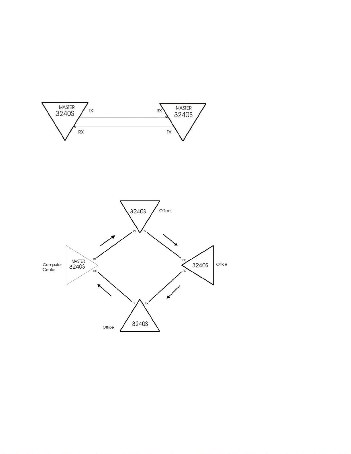
The 3240S can operate in Point-to-Point or Master/Slave Ring applications.
In a Point-to-Point application, the multiplexer is an extension of the computer port that connects two
points on a one-to-one basis; see Figure 3. Use the point-to-point application for either a managed or
a non-managed 3240S.
Figure 3. Typical Point-to-Point Application
In a Master/Slave Ring application, one multiplexer is designated as the master; it supplies the clock
to the slave units; see Figure 4. Use the master/slave ring application with a non-managed 3240S.
Note: The SNMP Module supports only local status and control for Master/Slave Ring applications.
Figure 4. Typical Master/Slave Ring Application
1-2 3240S Fiber-Optic Multiplexer

EdgeAccess
Equipment Options
The 3420S includes options for power, fiber optic cables types, redundancy, and management.
Power supply options include AC or DC and single or dual (redundant) power supplies with
connectors on the rear panel; see Figure 2. To reduce the load on each supply and extend their life,
both supplies provide power at the same time. If a supply fails, the power supply monitor card turns
off the corresponding Power LED, and, optionally, sends an alarm to the network management
module.
Fiber optic options includes single or dual (redundant) fiber optic transmitters and receivers. If the
primary transmitter or receiver fails, the 3240S turns on the alarm LED and, optionally, sends an
alarm to the network management module. An optional HI/LO power switch for each transmitter
(except low-power transmitters) provides compensation for link losses of typically more or less than 6
dB. Use the 3240S with 50/125 and 62.5/125 micron multimode fiber optic cable or single mode
8-10/125 micron fibers, depending on the transmitter option. The transmitter options include:
• 850 nm transmitter for multimode fiber only
• Low-power 1300 nm transmitter for multimode or single mode fiber
• High-power 1300 nm transmitter for multimode or single mode fiber
• Long-distance 1550 nm transmitter for single mode fiber only
The SNMP Management module can be installed either at the factory or in the field (for details, see
page 2-4). See Figure 1. The module provides two ports.
• 9-Pin RS-232 Serial Port Supports RS-232 protocols
• 10BASE-T Port Supports standard 10 Mbps Ethernet
3240S Fiber-Optic Multiplexer 1-3/(1-4 Blank)


EdgeAccess
Chapter 2
Hardware Setup and Non-Managed Use
The 3240S supports the T1 and E1 I/O cards. This chapter describes the switch and jumper settings
and LEDs for the system and the I/O cards. If you choose to use the 3240S as a non-managed system,
it will be ready for operation at the end of the setup and installation.
Before installing the 3240S, unpack it and its accessories; save the shipping carton and packing
material for reuse. Inspect the 3420S and shipping carton; if it is damaged, file a claim with the
freight carrier. Canoga Perkins is not liable for damage in shipment.
Setting Up I/O Cards
The 3240S supports T1 and E1 I/O cards.
Physical Slots and Time Slots
The 3240S divides the front-end bandwidth into four logical time slots; each card, either T1 or E1,
uses two time slots. You can insert a card in either physical slot, but each card can communicate only
with the card that uses the same time slots in another 3240S. Each pair of time slots can be used only
once. In general, set the card in physical slot 1 to time slots 1 and 3; set the card in physical slot 2 to
time slots 2 and 4. To avoid confusion, the management software flags an error if cards with the
same time slots are in different physical slots, although it does not affect system operation.
T1X, 4-Port I/O Card
Each T1X card supports four T1 channels and either Binary 8 Zero Substitution (B8ZS) or Alternate
Mark Inversion (AMI) line coding, uses two time slots, and uses one physical slot in a chassis. The
T1X card includes four connectors, all either female DA-15 or RJ-48C and configured as DCE.
Chapter 5 lists all connector pin assignments.
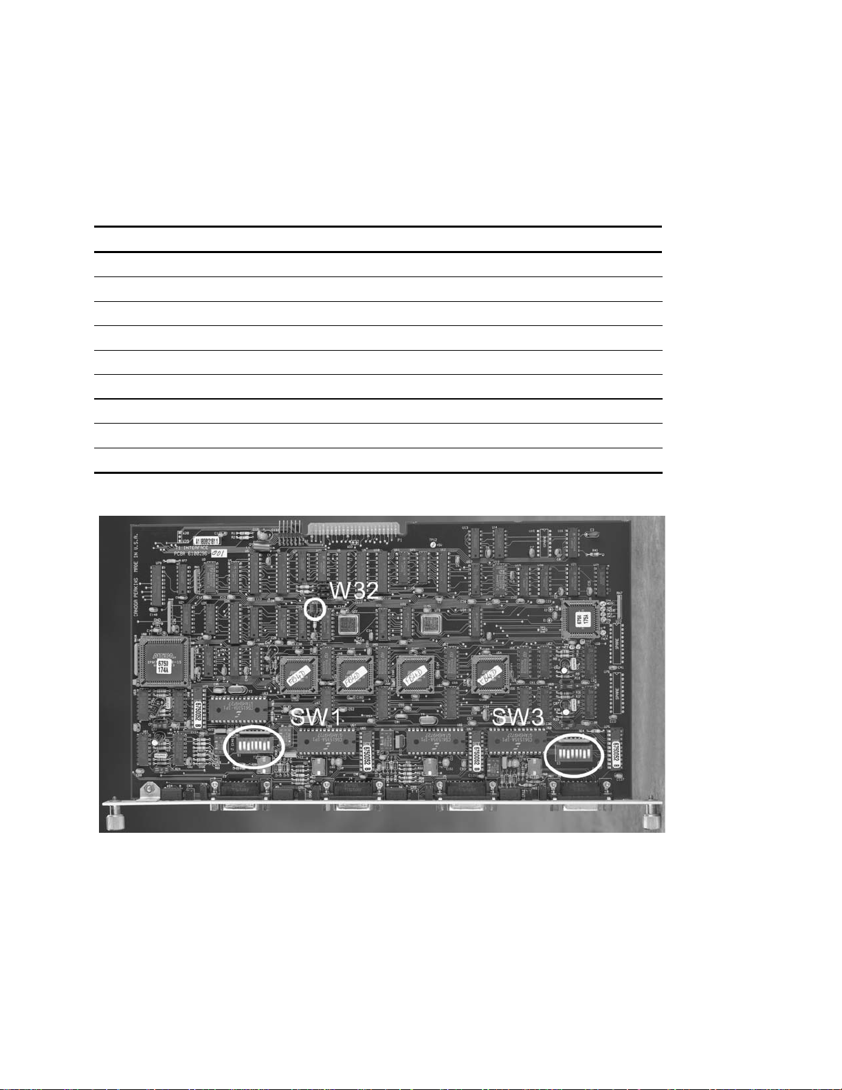
To set up the T1X card, see Figure 5 and follow these steps:
1. Set the time slot at jumper W32. Set both ends of the same link to the same time slot. Install the
jumper for time slots 1 and 3. Remove the jumper for time slots 2 and 4.
2. Switches SW1 and SW3 control the line length and line coding for the ports:
• Port 1: Line coding, SW1, 4; line length, SW1, 1-3
• Port 2: Line coding, SW1, 8; line length, SW1, 5-7
• Port 3: Line coding, SW3, 4; line length, SW3, 1-3
• Port 4: Line coding, SW3, 8; line length, SW3, 5-7
3240S Fiber-Optic Multiplexer 2-1
EdgeAccess
a. Both ends of each link must use the same type of line coding; set SW1 and SW3 positions 4
and 8. For B8ZS, set the switch to closed (C). For AMI, set the switch to open (O). If you
will control line coding through the software, set the switch to open.
b. Set the line length for each port in your system; see Table 1.
Table 1. T1 Switch Settings for Line Length
Line Length Application SW1 or SW3
1 2 3 5 6 7
0-133 ft. *DSX-1 ABAM Wire AT&T 600B/600C O O C O O C
133-266 ft. *DSX-1 ABAM Wire AT&T 600B/600C C C O C C O
266-399 ft. *DSX-1 ABAM Wire AT&T 600B/600C O C O O C O
399-599 ft. *DSX-1 ABAM Wire AT&T 600B/600C C O O C O O
533-655 ft. *DSX-1 ABAM Wire AT&T 600B/600C O O O O O O
AT&T CB113 Repeater O C C O C C
FCC Part 68, Opt A CSU Network Infc C O C C O C
ANSI T1.403 CSU Network Infc O O C O O C
* DSX-1 ABAM: T1 electrical interface specification for 22 gauge unshielded twisted pair.
Figure 5. T1X I/O Card
2-2 3240S Fiber-Optic Multiplexer
EdgeAccess
E1X, 3-Port I/O Card
The E1X card supports three channels and either High Density Binary Three (HDB3) or AMI line
coding, uses two time slots, and uses one physical slot in the chassis. The E1X card includes three
connectors, either 75 ohm BNC or DA-15, configured as DCE. Chapter 5 lists all connector pin
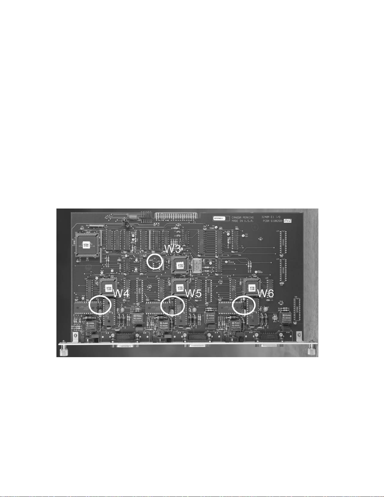
assignments. To set up the E1X card, see Figure 6 and follow these steps:
1. Set the time slot at jumper W3. Both ends of each link must be set to the same time slot. Install
the jumper for time slots 1 and 3. Remove the jumper for time slots 2 and 4.
2. Jumpers W4, W5, and W6 control the line coding for the ports:
• Port 1: W4
• Port 2: W5
• Port 3: W6
Both ends of each link must be set to the same line coding. For HDB3, install the jumper. For
AMI, remove the jumper. If you will control the line coding through the software, install the
jumper.
Figure 6. E1X I/O Card
3240S Fiber-Optic Multiplexer 2-3
 Loading...