

CANOGA PERKINS 2361 T1 User Manual

2361 T1 Modem
User Manual

The EdgeAccess Universal Chassis System
NOTICE
Canoga Perkins reserves the right to change or update the contents of this manual and to change
the specifications of its products at any time without prior notification. Every effort has been
made to keep the information in this document current and accurate as of the date of publication
or revision. However, no guarantee is given or implied that the document is error free or that it is
accurate with regard to any specification.
Canoga Perkins has prepared this manual for use by customers and Canoga Perkins personnel as a
guide for the proper installation, operation and/or maintenance of Canoga Perkins equipment. The
drawings, specifications and information contained in this document are the property of Canoga
Perkins and any unauthorized use or disclosure of such drawings, specifications and information
is prohibited.
Canoga Perkins Corporation
20600 Prairie Street
Chatsworth, CA 91311-6008 USA
(818) 718-6300
FAX: (818) 718-6312
Web Site: www.canoga.com
e-mail: fiber@canoga.com
Copyrightã 2000 - 2005 Canoga Perkins
All Rights Reserved
EdgeAccess
Universal Chassis System
2361 T1 Modem
User Manual
Product Number: 2361-UM
Part Number: 6912271
Rev. L 09/2005
To reference Technical Advisories and Product Release Notes, go to Canoga Perkins'
website: http://www.canoga.com/cservice.htm
®
ii
2361 Modem Users Manual

The EdgeAccess Universal Chassis System
CAUTION!
This product may contain a laser diode emitter operating at a wavelength of 1300nm - 1600nm. Use of
optical instruments (for example: collimating optics) with this product may increase eye hazard. Use of
controls or adjustments or performing procedures other than those specified herein may result in hazardous
radiation exposure.
Under normal conditions, the radiation levels emitted by this product are under the Class 1 limits in 21 CFR
Chapter 1, Subchapter J.
NOTE!
The EdgeAccess Model 2361 T1 Modem is code transparent, it does not generate B8ZS coding. Therefore,
it is not to be used for direct connection to the PSTN. However, it can be connected to the PSTN provided
the compatible approved terminal equipment shall either supply signals with B8ZS encoding or be
approved to be connected directly to the PSTN.
ATTENTION!
Cet équipement peut avoir une diode laser émettant à des longueurs d'onde allant de 1300nm à 1600nm.
L'utilisation d'instruments optiques (par exemple : un collimateur optique) avec cet équipement peut
s'avèrer dangereuse pour les yeux. Procéder à des contrôles, des ajustements ou toute procédure autre que
celles décrites ci-après peut provoquer une exposition dangereuse à des radiations.
Sous des conditions normales, le niveau des radiations émises par cet équipement est en dessous des limites
prescrites dans CFR21, chapitre 1, sous chapitre J.
NOTICE!
This device contains static sensitive components. It should be handled only with proper Electrostatic
Discharge (ESD) grounding procedures.
NOTE!
Cet équipement contient des composants sensibles aux décharges électro-statiques. Il doit absolument
être manipulé en respectant les règles de mise à la terre afin de prévenir de telles décharges.
2361 Modem Users Manual
iii

The EdgeAccess Universal Chassis System
Table of Contents
Chapter 1 General Description .....................................................................................1-1
1.1 Product Description.................................................................................... 1-2
1.1.1 Management ...........................................................................................................1-2
1.1.2 Redundancy............................................................................................................1-3
1.1.3 Interchangeable Interfaces......................................................................................1-3
1.1.4 Alarms ....................................................................................................................1-3
1.1.5 Diagnostic and Test Functions ...............................................................................1-4
1.1.6 Standalone Modem.................................................................................................1-4
1.1.7 Main Module LEDs:...............................................................................................1-5
1.1.8 ELIM LEDs............................................................................................................1-5
1.1.9 OLIM LED:............................................................................................................1-5
1.1.10 Rackmount Modem..............................................................................................1-5
1.2 ELIM Interface Options............................................................................... 1-5
1.3 OLIM Interface Options .............................................................................. 1-6
1.4 Loss Budget Considerations ...................................................................... 1-6
1.5 2361 Modem Operating At E1 Rate ........................................................... 1-7
1.6 Applications................................................................................................ 1-7
Chapter 2 Installation ....................................................................................................2-1
2.1 Unpacking and Installing the Rackmount Modem ...................................... 2-1
2.1.1 Inserting an ELIM or OLIM...................................................................................2-2
2.2 Unpacking and Installing the Standalone Modem ...................................... 2-2
2.2.1 Mounting the Standalone Modem..........................................................................2-3
2.2.2 Cabling the Standalone Modem .............................................................................2-3
2.3 Standalone Modem Alarm Relay Contacts................................................. 2-3
2.3.1 Input Alarms...........................................................................................................2-4
2.3.2 Output Alarms:.......................................................................................................2-4
2.4 Providing Power to the 2361 DC Modem ................................................... 2-5
2.5 Electrical Interfaces.................................................................................... 2-6
2.5.1 RJ-48 T1 * as a DCE Interface................................................................. 2-6
2.5.2 DA-15 Pin Out.......................................................................................... 2-7
Chapter 3 Booting Up The Modem ..............................................................................3-1
3.1 Main Module Indicators and Switches........................................................ 3-1
3.1.1 Main Module LED Function..................................................................................3-1
3.1.2 MDM / TRM Switch..............................................................................................3-3
iv
2361 Modem Users Manual

The EdgeAccess Universal Chassis System
3.2 ELIM Indicators and Switches .................................................................... 3-4
3.3 OLIM Indicator............................................................................................ 3-4
Chapter 4 Configuring the 2361 Modem .....................................................................4-1
4.1 General Screen Format.............................................................................. 4-1
4.2 VT100 Terminal Screens............................................................................ 4-2
4.3 Main Menu ................................................................................................. 4-3
4.3.1 Setting a Password .................................................................................................4-4
4.3.2 Setting Date and Time............................................................................................4-4
4.3.3 Setting Modem / SLIP / PPP Baud Rate Configuration.........................................4-5
4.3.4 Specifying a Modem Initialization String ..............................................................4-5
4.3.5 Resetting the Configuration to Default Values ......................................................4-5
4.3.6 Exporting Modem Configuration Settings .............................................................4-5
4.4 System Configuration................................................................................. 4-6
4.4.1 Hardware Configuration Status..............................................................................4-7
4.4.2 Setting Functional Configuration...........................................................................4-8
4.4.3 Setting up and Configuring Modem Alarms..........................................................4-8
4.4.4 Alarm Functions and Default Settings ...................................................................4-9
4.4.5 Interpreting System Alarms .................................................................................4-10
4.4.6 Configuring Modem Traps...................................................................................4-13
4.4.7 Standalone Modem Alarm Input Settings ............................................................4-14
Chapter 5 Diagnostics ....................................................................................................5-1
5.1 Link Self-Test ............................................................................................. 5-1
5.2 Link Error Counter...................................................................................... 5-1
5.3 Standalone Modem Diagnostic Tools......................................................... 5-2
5.4 Loopback and Bit Error Rate Testing ......................................................... 5-3
5.4.1 Normal Operation....................................................................................................5-5
5.4.2 Local Loopback Operation.....................................................................................5-5
5.4.3 Remote Loopback ..................................................................................................5-6
5.4.4 Remote Loopback with BERT ...............................................................................5-6
5.4.5 Local Bi-directional Loopback...............................................................................5-7
5.4.6 Remote Bi-directional Loopback ...........................................................................5-7
5.4.7 Local Loopback at Both Ends ................................................................................5-8
Chapter 6 Troubleshooting ...........................................................................................6-1
6.1 New Installations........................................................................................ 6-1
6.2 Fiber Optic Related Problems .................................................................... 6-2
6.3 Connecting Equipment Related Problems.................................................. 6-2
6.4 2361 Modem Related Problems................................................................. 6-2
6.4.1 T1/E1 Switch..........................................................................................................6-2
6.4.2 Repeated Resets......................................................................................................6-3
6.4.3 ELIM Switched with OLIM...................................................................................6-3
2361 Modem Users Manual
v

The EdgeAccess Universal Chassis System
6.4.5 Software Version Incompatibility ..........................................................................6-3
6.4.6 Data Not Transmitting............................................................................................6-3
6.5 Replacing Modules..................................................................................... 6-4
6.6 Data Transmission Errors........................................................................... 6-4
6.7 Dial-up Connection to Standalone Modem................................................ 6-4
6.8 Intermittent Problems in Data Transmission............................................... 6-5
Chapter 7 Redundant Configurations..........................................................................7-1
7.1 Creating a Redundant Circuit....................................................................................7-3
7.1.1 Special Redundancy ELIMs and Cables ................................................................7-4
7.2 Setting Up Redundancy ............................................................................. 7-4
7.2.1 Redundancy Mode Options....................................................................................7-5
7.3 Important Definitions for Redundant Configurations................................... 7-5
7.3.1 Standby Modem State and Activity .......................................................................7-6
Chapter 8 Upgrading Modem Software.......................................................................8-1
8.1 Determining Current Software and Version Availability.............................. 8-2
8.2 Obtaining the Software............................................................................... 8-2
8.3 Installing the New Software........................................................................ 8-3
8.3.1 Installing in a Managed UCS Chassis....................................................................8-3
8.3.2 Installing into a Standalone Modem Via TFTP .....................................................8-3
8.3.3 Installing into a Standalone Modem Via the Serial Port .......................... 8-4
Chapter 9 2361 Specifications .......................................................................................9-1
Appendix A Warranty ..................................................................................................A-1
vi
2361 Modem Users Manual

The EdgeAccess Universal Chassis System
List of Figures
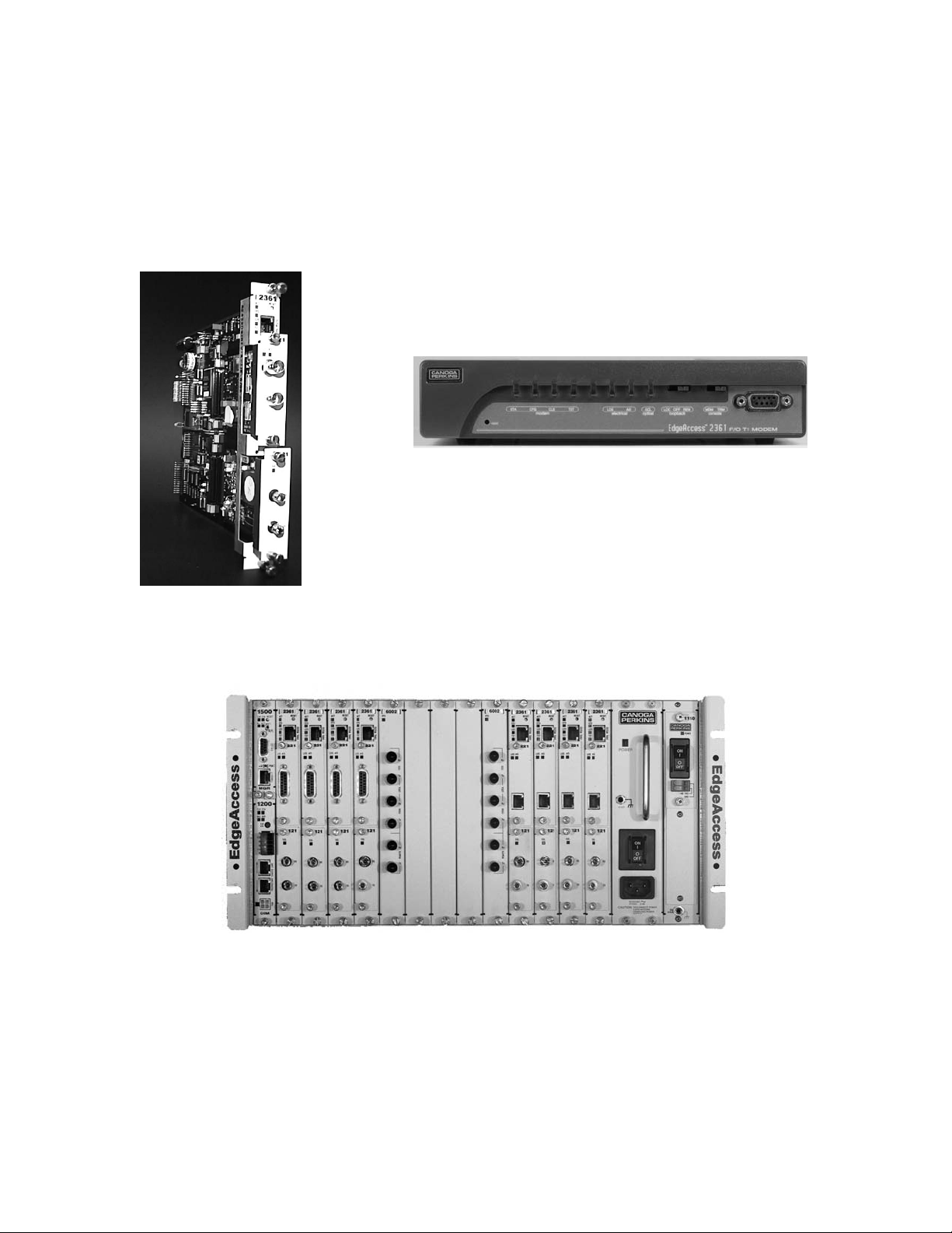
Figure 1 Rackmount 2361 Modem.............................................................................................. 1-1
Figure 2 Standalone 2361 Modem...............................................................................................1-1
Figure 3. Several 2361 Modems Installed in a Universal Chassis System..................................1-1
Figure 4. BNC (E1 Only), DA-15, and RJ-48 ELIMs .................................................................1-3
Figure 5. An Optical Line Interface Module (OLIM)..................................................................1-3
Figure 6. Main Module and ELIM LEDs ....................................................................................1-5
Figure 7. Distance Guide for the 2361 Modem ............................................................................1-6
Figure 8. T1/E1 Switch on a Standalone Modem......................................................................... 1-7
Figure 9. The 2361 Modem Extends a T1 Signal Over Fiber Optic Cables ................................. 1-7
Figure 10. 2361 Modem Applications ..........................................................................................1-8
Figure 11. The Universal Chassis System with No Modules .......................................................2-1
Figure 12. The Universal Chassis System Filled with Modules...................................................2-1
Figure 13. Screw Hole Locations for Mounting Modem in Various Configurations ...................2-3
Figure 14. Input and Output Alarm Relay Connectors(AC Version) ...........................................2-3
Figure 15. Input and Output Alarm Relay Connectors (DC Version) ..........................................2-4
Figure 16. DC Power Entry Close-up........................................................................................... 2-5
Figure 17. RJ-48 Cable Pin Out....................................................................................................2-6
Figure 18: DA-15 Pin Out. ...........................................................................................................2-7
Figure 19. Close-up of the Rackmount 2361 Modem LED.......................................................... 3-1
Figure 20. LEDs, Interface, and Switches on the 2361 Standalone Modem ................................3-3
Figure 21. ELIMs, OLIMs, and Alarm Connectors Are on the Rear of the Standalone Modem 3-3
Figure 22. All Modem Screens Have Common Navigational Methods .......................................4-1
Figure 23. The Modem Main Menu Screen.................................................................................. 4-3
Figure 24. The Utilities Screen..................................................................................................... 4-4
Figure 25. The System Configuration Screen...............................................................................4-6
Figure 26. The Hardware Configuration Screen (First of two screens)........................................4-7
Figure 27. The Functional Configuration Screen .........................................................................4-8
Figure 28. The Alarm Output Configuration Screen ....................................................................4-9
Figure 29. The System Alarms Screen .......................................................................................4-10
Figure 30. Set Traps by Accessing the Link Level Trap Configuration Screen......................... 4-13
Figure 31. The Link Error Counter Screen, Shown Here in a Redundant System ......................5-1
Figure 32. The Standalone 2361 Modem......................................................................................5-2
Figure 33. Diagnostics Screen Provides Access to BERT and Loopback Testing....................... 5-3
Figure 34. The Modem in Normal Operation............................................................................... 5-5
Figure 35. The Modem in Local Loopback Operation .................................................................5-5
Figure 36. The Modem in Remote Loopback Operation.............................................................. 5-6
Figure 37. Remote Loopback with BERT .................................................................................... 5-6
Figure 38. Local Bi-directional Loopback....................................................................................5-7
Figure 39. Remote Bi-directional Loopback ................................................................................5-7
Figure 40. Local Loopback at Both Ends. ...................................................................................5-8
Figure 41. Fiber Path Redundancy ...............................................................................................7-1
Figure 42. Full Redundancy..........................................................................................................7-2
Figure 43. Redundancy Circuit Diagram...................................................................................... 7-3
Figure 44. The Functional Configuration Screen .........................................................................7-4
Figure 45. Link Self Test Running Continuously on an Auxiliary Channel at 48.25 kbps ..........7-7
Figure 46. The Software Upgrade Screen..................................................................................... 8-2
Figure 47. To Download a Software Revision, Type "3" From the Software Upgrade Screen....8-3
2361 Modem Users Manual
vii

The EdgeAccess Universal Chassis System
List of Tables
Table 1. RJ-45 8-pin Modular Pin Out ........................................................................................4-2
Table 2 EIA-232 DE-9 Pin Out ..................................................................................................4-3
Table 3: System Configuration Option Definitions......................................................................4-6
Table 4: Alarm Output Configuration Option Definition.............................................................4-9
Table 5: System Alarm Option Definitions ................................................................................4-11
Table 6: Alarm Trap Option Definitions ....................................................................................4-14
viii
2361 Modem Users Manual
The EdgeAccess Universal Chassis System
Chapter 1
General Description
The EdgeAccess Model 2361 is a G.703 compliant T1 fiber optic modem. It is a microprocessorbased modem that supports the standard speed of 1.544Mbps, providing a transparent fiber optic
link extension for any metallic T1, regardless of line coding.
Figure 1. The Standalone 2361 Modem
Figure 2. The Rackmount 2361 Modem
Figure 3. Several 2361 Modems Installed in a Universal Chassis System
The 2361 is available as a rackmount card or a standalone unit. Both versions are available as
120/240VAC or -48VDC. For applications that require many co-located modems, the
EdgeAccess Universal Chassis System (UCS) provides modem capacities of up to 15 rackmount
modems per chassis and up to 120 modems under one Domain Management Module (DMM).
2361 Modem Users Manual
1-1

The EdgeAccess Universal Chassis System
1.1 Product Description
The 2361 modem contains three main components:
• Main Module The modem's main module consists of CPU modem management hardware,
I/O control and memory, a custom composite XL Mux/Demux device (gate array), Loopback
Support Circuitry, Message Bus, Redundancy Interface Units, and Front Panel Indicators and
Switches.
• Electrical Line Interface Module (ELIM): An I/O Module available in a variety of
electrical interfaces. It provides isolation between the modem main module and the attached
metallic cable interface and transforms differential signals to bipolar line drive signals.
• Optical Line Interface Module (OLIM): An I/O module available in a variety of optic
wavelength interfaces. The optical link will carry data from both the network equipment (i.e.,
payload) and the network management processor (IMDL). Data is transmitted from the main
modem board, routed to the OLIM's driver circuitry, which in turn, drives the optical
transmitter.
The received data from the optical receiver will be amplified and then restored to TTL logic
levels before being delivered to the modem board.
All three components are hot-swappable, meaning that a module can be replaced without resetting
the entire unit.
1.1.1 Management
Configuration and management is accomplished via a local terminal. Modems can be managed in
the following ways:
• Local terminal directly connected to the modem's serial port in VT100 mode
• Local terminal connected through the Universal Chassis System's Domain Management
Module (DMM)
• SNMP, through the UCS Domain Management Module
• SNMP, utilizing optional TCP/IP access via the modem's serial port (standalone only)
In each case, menu driven, user friendly screens provide end-to-end configuration, status, and
control of the link, including remote and redundant modems.
SNMP management, via DMM: Provides a Network Manager with all data, via Intranet or
local PC management system.
DMM: Provides management data on all modems and other modules in the Universal Chassis
System, including remote modems.
VT100 Terminal Access: Provides access to all individual modem software screens, and their
remote partners.
SNMP management & telnet, over SLIP/PPP port: Available as an option in the standalone
units.
1-2
2361 Modem Users Manual
The EdgeAccess Universal Chassis System
1.1.2 Redundancy
The 2361 provides two redundancy configuration types. In one type, only two modems are used,
but the fiber between them is duplicated. The other type requires four modems and two complete
fiber paths.
Fiber Path Redundancy: Two pairs of fibers are run between two modems. Only the fiber,
therefore, is redundant. Failure of one fiber pair causes a switchover to the other pair. A special
redundant OLIM is required for Fiber Path Redundancy.
Full Redundancy: The modems and the fiber path are both redundant. A failure in either causes
data to switch over to the alternate path. Bit Error Rate testing is continually passing through the
redundant path, to insure its operability.
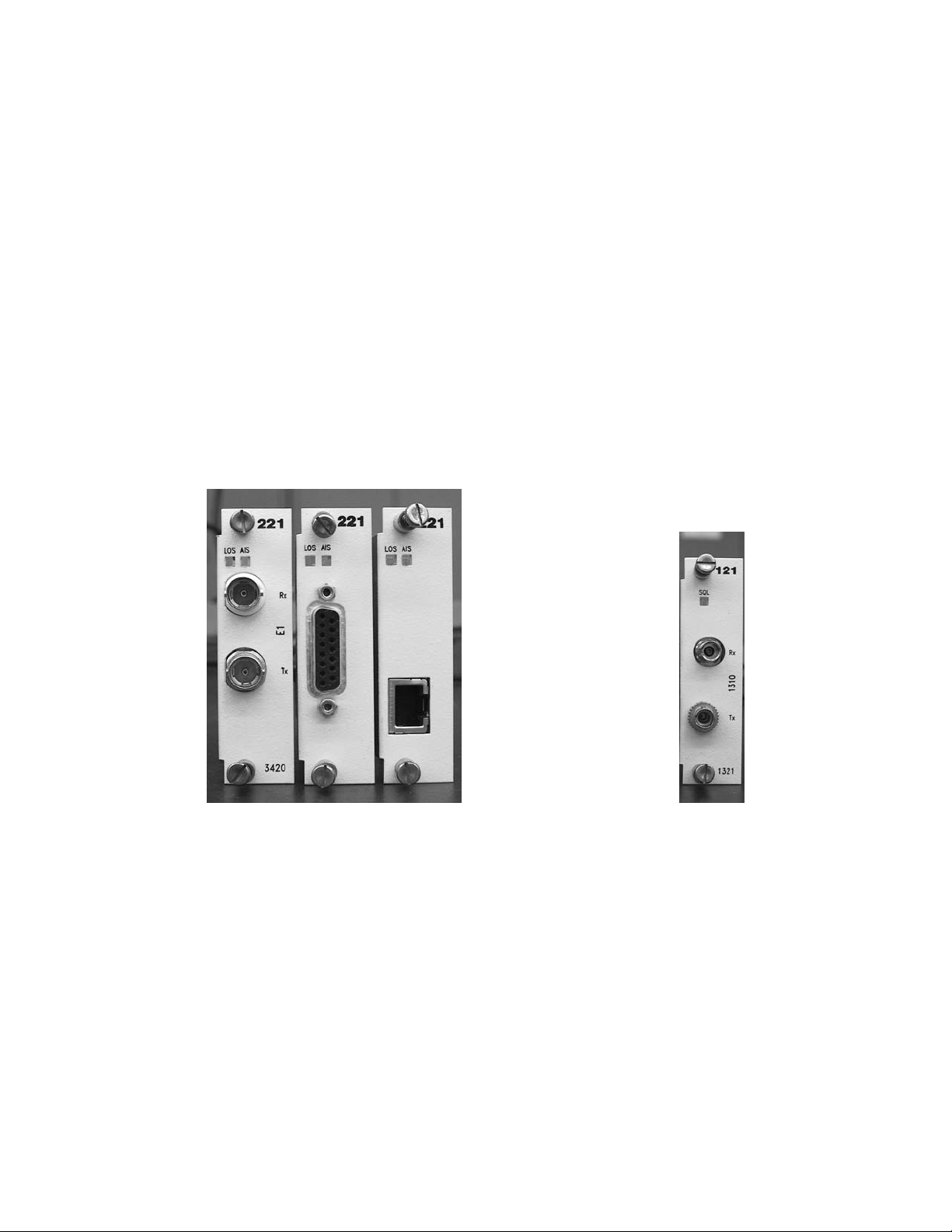
1.1.3 Interchangeable Interfaces
A variety of ELIMs and OLIMs provides flexible interface interchangeability.
Figure 4. BNC (E1 Only), DA-15, and RJ-48 ELIMs Figure 5. An Optical Line Interface
Module (OLIM)
1.1.4 Alarms
The Standalone 2361 Modem provides input and output dry alarm relay contacts on the rear
panel. These allow management personnel to collect and route alarm data to an external audio or
visual "shop" alarm, provided by the user.
The 2361 rackmount modem, as a component of the Universal Chassis System (UCS, passes
alarm data to the UCS Chassis Interconnect Module (CIM), where it is routed via dry contact
alarm relays to an external alarm, provided by the user.
2361 Modem Users Manual
1-3

The EdgeAccess Universal Chassis System
1.1.5 Diagnostic and Test Functions
The 2361 modem provides complete Loopback feature, Continuous Self Test, and extensive link
and Bit Error Rate Testing.
1.1.6 Standalone Modem
The standalone version comes in a compact enclosure for desktop, shelf, rack, or wall mount
installations. It has a built-in AC or DC power supply and utilizes the same ELIMs and OLIMs as
the rackmount version.
On the front panel, the 2361 standalone modem includes the following:
• 1 DE 9 EIA-232 port
• An MDM/TRM switch
• In the MDM position, the modem transmits a modem signal via the serial port
(port is emulating DTE). The modem will therefore, support modem dial-up
connections.
• In the TRM position, the port emulates VT100 terminal mode (port is emulating DCE).
• A three-position loopback switch to select Local Loopback, Remote Loopback or off-
position. The switch will be operational only if the loopback mode is set in "hardware mode"
(See Chapter 7).
• A Reset switch. This switch resets the processor without affecting the flow of the payload.
On the rear panel, the 2361 Standalone modem includes the following:
• Major and Minor Alarm Input Connector
• Major and Minor Alarm Output Connector
• A Redundancy Cable used when the standalone modem is in redundant operation.
1-4
2361 Modem Users Manual
The EdgeAccess Universal Chassis System
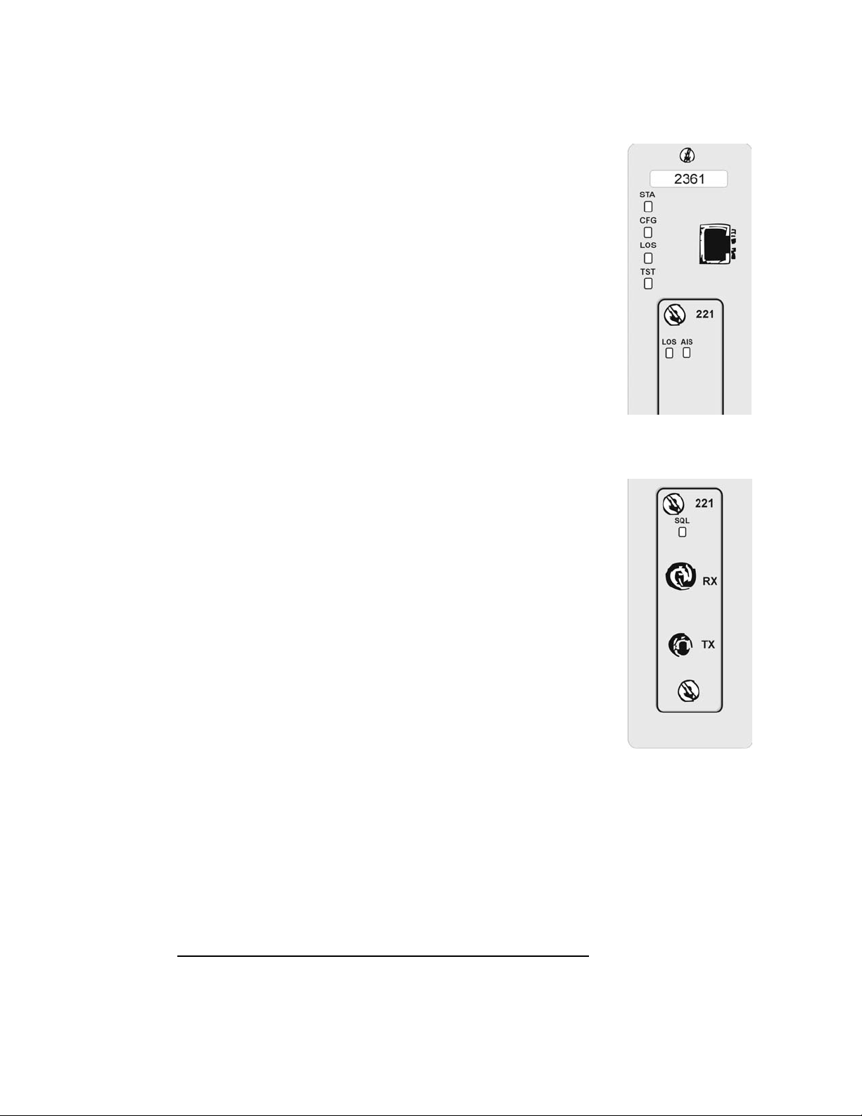
1.1.7 Main Module LEDs:
STA Green/Red/Yellow Modem Status
CFG Red Configuration error
CLS Red Composite Receive
Loss of Sync
TST Yellow/Red Loopback and
BERT test
1.1.8 ELIM LEDs
LOS Red Loss of Signal
AIS Yellow "all 1's"
Note: LEDs report local modem errors with solid indicators, and remote
modem errors with flashing indicators.
1.1.9 OLIM LED:
SQL Green Receiving acceptable Signal
Quality Level
Red Receiving below acceptable
Signal Quality Level
1.1.10 Rackmount Modem
On the front panel, the rackmount modem includes the following:
• 1 RJ-45 EIA-232 port for terminal port management. It is available in
DCE.
• A Reset switch. This switch resets the processor without affecting the flow of
the payload.
Figure 6. Main Module and
ELIM LEDs
1.2 ELIM Interface Options
There are two ELIM types. All electrical interfaces comply with the ITU G.703 standard. ELIMs
with RJ-48 connectors are available with DTE or DCE configuration. The type of configuration
is indicated on the front panel of the ELIM.
Connector Cable Impedance
RJ-48 Twisted Pair 100 Ohm
DA-15 Twisted Pair 100 Ohm
2361 Modem Users Manual
1-5
The EdgeAccess Universal Chassis System
1.3 OLIM Interface Options
There are several options for selecting optical transceivers. These options accommodate the
following needs:
• Differences in the fiber optic cable core size used in the network
• Differences in operating wavelengths
• Differences in transceiver power budget and connector styles
The options available are as follows:
Wavelength Loss Budget Connector
Fiber Type
850nm LED 16dBm ST
Multimode
1310nm Laser 26dBm ST, FC/PC, SC
Single mode
1310nm Laser 17dBm ST, FC/PC, SC
Single mode
1550nm Laser 26dBm ST, FC/PC, SC
Single mode
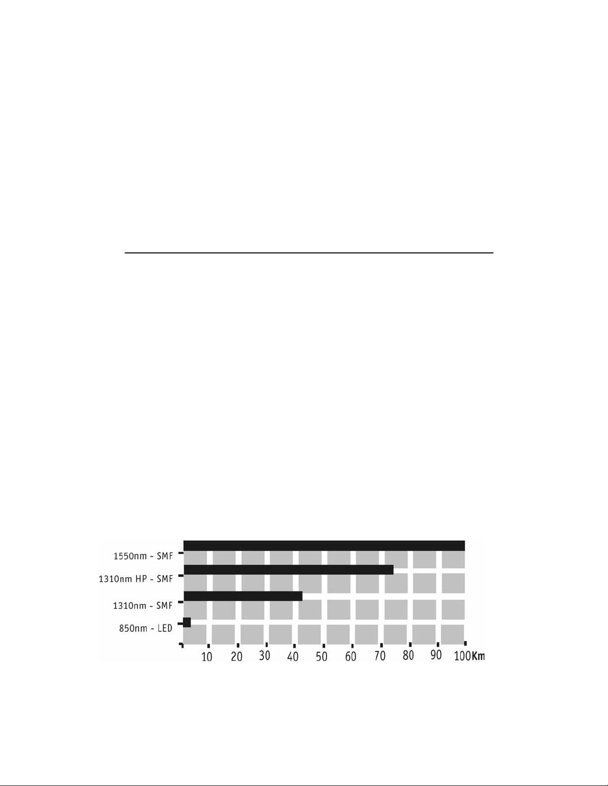
1.4 Loss Budget Considerations
The maximum possible distance with either standard or long distance versions is dependent on
the overall power loss of the fiber optic link. This is called the link loss. The launch power of the
transmitter along with the receiver sensitivity, determines the loss budget. To insure normal
operation over a long term, the link loss should be at least 3dB less than the loss budget for the
modem.
Additionally, see the distance guide chart in Figure 7.
1-6
Figure 7. Distance Guide for the 2361 Modem
2361 Modem Users Manual
The EdgeAccess Universal Chassis System
1.5 2361 Modem Operating At E1 Rate
While the 2361 modem is a T1 modem, it can also function in E1 mode. This can be
accomplished by changing a switch position on the Main Module. For Rackmount modems,
remove the modem from the chassis, and locate the T1/E1 switch on the board. Then, change the
switch to E1.
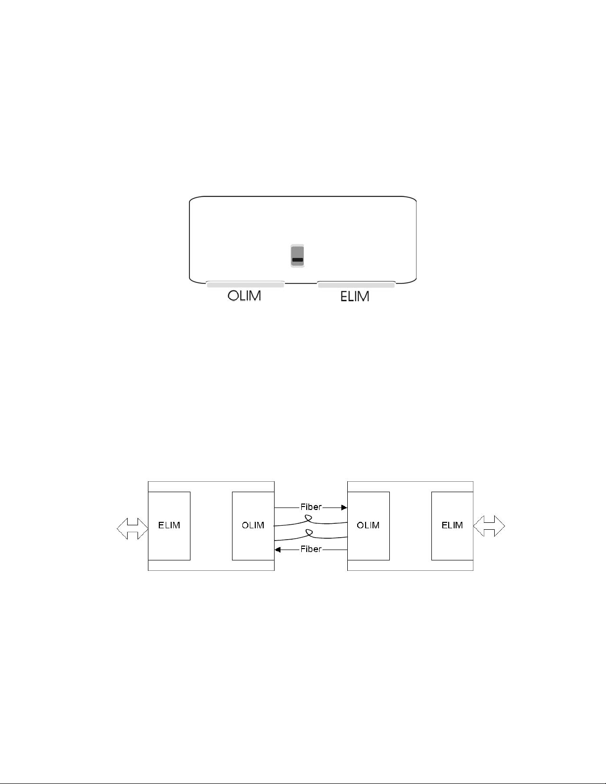
For a standalone modem, the switch is accessible by removing the ELIM or OLIM, reaching
inside between the ELIM and the OLIM, and toggling the switch.
Figure 8. T1/E1 Switch on a Standalone Modem
1.6 Applications
The modem's general purpose is to extend the reach of a pair of T1 signal over fiber optic cables,
as shown below:
• Payloads pass through without regard to codes or frames.
• In Redundant applications, continuous Bit Error Rate Testing on the inactive modem is
performed.
T1 Signal,
Router,
PBX, etc.
Figure 9. The 2361 Modem Extends a T1 Signal Over Fiber Optic Cables
Applications include:
T1 Signal,
Router,
PBX, etc.
• Carrier Applications
• Campus Voice Applications
• Campus Data Applications
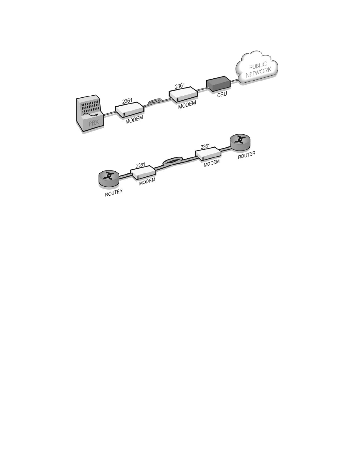
Figure 10 depicts 2361 modem applications.
2361 Modem Users Manual
1-7
The EdgeAccess Universal Chassis System
Figure 10. 2361 Modem Applications
1-8
2361 Modem Users Manual
The EdgeAccess Universal Chassis System
Chapter 2
Installation
In this chapter, installing and powering the 2361 modem is discussed.
2.1 Unpacking and Installing the Rackmount Modem
Each 2361 modem is factory tested and shipped in protective cartons. After unpacking the unit
and accessories, retain the shipping carton and protective packing in the event a need arises for
returning it to the factory.
To install the 2361 modem, do the following:
1. If the Universal Chassis System Chassis Model 1000 has not yet been installed, do so now.
Also install the optional CIM and DMM modules. The 2361 modem can be installed at any
time into an operating chassis.
2. The modem consists of the main module, as well as ELIMs and OLIMs, which may have
been shipped already inserted into the main module. The modem can be inserted into any
numbered available slot in the UCS 1000 chassis. The slots are numbered on the Chassis
metal strips near where the screws are inserted.
Note: If a redundant application will be used, the primary modem must be inserted
into an odd numbered slot (slots are numbered on the chassis metal strip near where
the modem's screws are inserted). The secondary modem must be inserted into the first
even numbered slot to the right, (For example: 1, 2, or 7, 8).
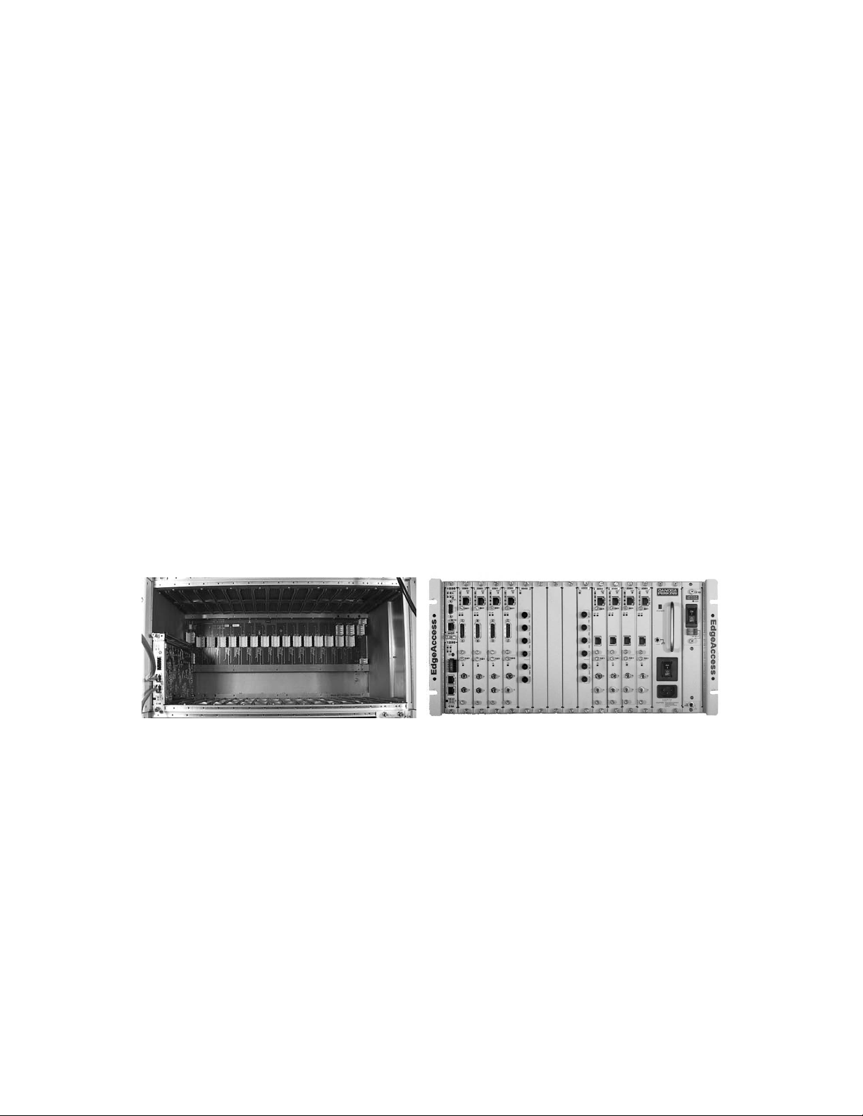
Figure 11. The Universal Chassis System with
No Modules
3. When inserted correctly into position, you will feel and hear the modem connect firmly with
the backplane. It should fit snugly, and will not need to be forced.
4. Hand-tighten the knurled knobs, which will fasten the modem firmly into place. No
screwdriver is necessary.
5. Additional modems can be inserted into the chassis at any time, and will be detected by the
Universal Chassis System without rebooting the UCS. The modem receives power from the
backplane.
Figure 12. The Universal Chassis System
Filled with Modules
2361 Modem Users Manual
2-1

The EdgeAccess Universal Chassis System
6. When inserted into an active chassis, the modem's LEDs will display amber while booting. If
a DMM is installed and operating, the DMM will detect the presence of the modem, and
begin reporting modem status on appropriate software screens. For LED activity, see the LED
section of this manual.
7. To avoid configuration errors, attach the appropriate cables to the modem's ELIMs and
OLIMs, carefully labeling all Tx and Rx cables clearly.
8. If no configuration errors are present, data will begin passing.
2.1.1 Inserting an ELIM or OLIM
ELIMs and OLIMs (Electrical or Optical Line Interface Modules) slide in and out of the modem's
main module, much as the modem itself slides into the Chassis. The rackmount cards and the
standalone units use the same LIMs.
ELIMs are always positioned in the top slot, and OLIMs on the bottom.
2.2 Unpacking and Installing the Standalone Modem
Each 2361 modem is factory tested and shipped in protective cartons. After unpacking the unit
and accessories, retain the shipping carton and protective packing for reuse in the event a need
arises for returning it to the factory.
The standalone modem may be installed on a desktop, or mounted in a rack with side screws (see
Figure 13). Ensure that cables are away from foot traffic. The operator must have access to the
rear of the modem (for cable and dry alarm contact attachment), and the front of the modem (for
terminal interface access and viewing the modem's LEDs).
2-2
2361 Modem Users Manual
The EdgeAccess Universal Chassis System
2.2.1 Mounting the Standalone Modem
The standalone modem comes with mounting screw holes to facilitate wall mounting, rack
mounting, or dual (side-by-side) rack mounting. There are seven screw holes on each side of the
modem; however, it is not necessary to use each hole for all configurations. The diagram below
indicates the holes required for each configuration.
Figure 13. Screw Hole Locations for Mounting Modem in Various Configurations
2.2.2 Cabling the Standalone Modem
Make sure all cables are clearly labeled and set away from foot traffic. Attach the appropriate
cables to the modem's ELIMs and OLIMs. If no Configuration (CFG Alarm LED) errors are
detected, data will begin passing.
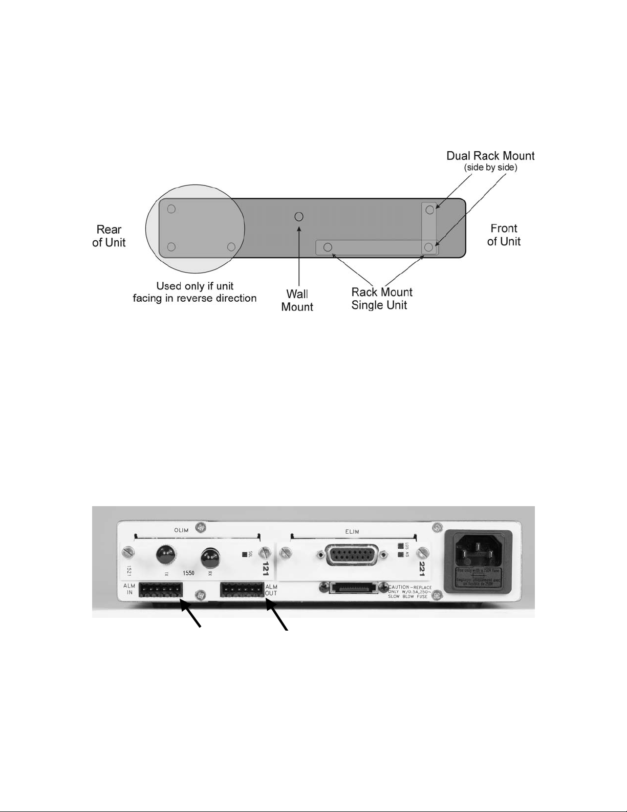
2.3 Standalone Modem Alarm Relay Contacts
The 2361 standalone Modem has alarm relay contacts, visible on the rear of the modem
(Figure 14).
Pin 1
Pin 1
Figure 14. Input and Output Alarm Relay Connectors(AC Version)
2361 Modem Users Manual
2-3

The EdgeAccess Universal Chassis System
J 19
Pin 1
J 16
Pin 1
Figure 15. Input and Output Alarm Relay Connectors (DC Version)
Viewing the rear panel of the modem, J19 is the leftmost (6) 6-pin modular connector; J16 is to
the right of J19. Pin 1 is on the right side of each modular connector.
2.3.1 Input Alarms
J19 (alarm input) connector pinout:
1 - Chassis Gnd.
2 - Minor alarm contact a
3 - Minor alarm contact b
4 - Chassis Gnd.
5 - Major alarm contact a
6 - Major alarm contact b
Operation:
An external contact closure between pins 5 and 6 will cause a MAJOR alarm
An external contact closure between pins 2 and 3 will cause a MINOR alarm
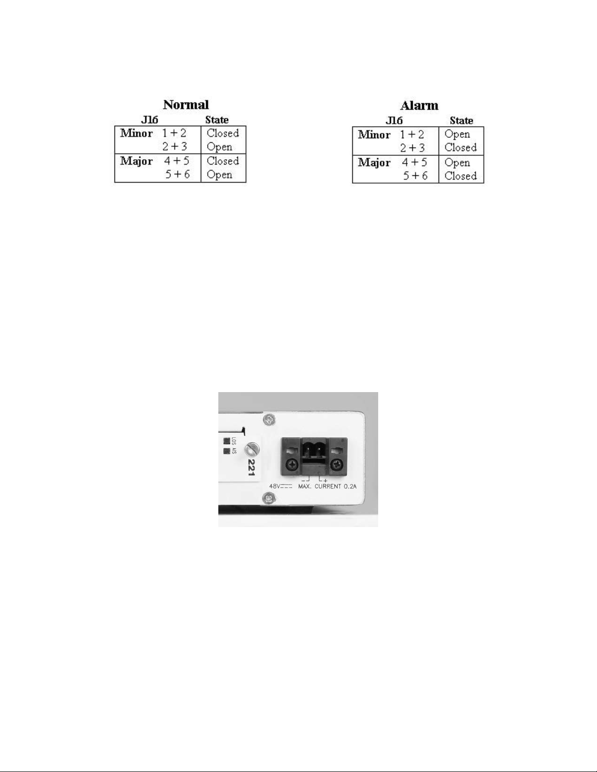
2.3.2 Output Alarms:
J16 (alarm output) connector pinout: (ref: de-energized/alarmed state)
1 - Minor alarm N/C
2 - Minor alarm common
3 - Minor alarm N/O
4 - Major alarm N/C
5 - Major alarm common
6 - Major alarm N/O
2-4
2361 Modem Users Manual
The EdgeAccess Universal Chassis System
Operation:
Note: When connecting the alarm output to an external source, use twisted pairs and terminate
the cable shield at the user side.
2.4 Providing Power to the 2361 DC Modem
The -48 volt base unit is intended for use with an external -48VDC power supply. A two piece
terminal block connector is provided. It is clearly marked as to which screw lug is to be attached
to the positive (+) and negative (-) 48 volts DC terminals.
Note: Check signal ground (GND) of the source supply and orient it to the Modem GND, or
chassis ground. Verify with a ohmmeter that (+) and (-) are not shorted prior to applying power.
Figure 16. DC Power Entry Close-up
Warning! Turn off the -48VDC power supply to be completely sure that there is no more
power. Use a voltmeter to measure the voltage across the negative (-) and
positive (+) source DC leads. Set the voltmeter to a range that makes it
capable of measuring up to 75VDC. The measurement across the positive and
negative leads should be zero (0) volts.
To provide power to the 2361 standalone modem DC version, do the following:
1. Remove the power terminal block from the rear panel of the unit.
2361 Modem Users Manual
2-5
The EdgeAccess Universal Chassis System
2. Using a 1/16-inch flat-blade (pocket) insulated screwdriver, loosen the two captive wire
installation screws on the terminal block to accommodate 16-22 AWG solid wire.
3. If you are establishing a color convention for wiring, use black for -48VDC and red for Gnd.
Remove ¼-inch insulation from wire ends. Avoid nicking the wire.
4. Connect the -48 Volt source DC power leads to the terminals on the power supply terminal
block. In so doing, you must strictly observe the following order of connection to the source
power supply wire:
(a) + terminal to red lead (GND)
(b) - terminal to black lead (-48VDC)
5. Tighten the two captive wire installation screws on the terminal block.
6. Plug the terminal block into the rear of the unit. Verify that the source wires are routed
downward.
7. Apply power and verify proper LED status of modem in power up condition (see Chapter 3).
2.5 Electrical Interfaces
The electrical interfaces on the 2361:
RJ-48 T1 (DCE) Interface Port
DA15 9-pin Command Port Interface on the standalone models
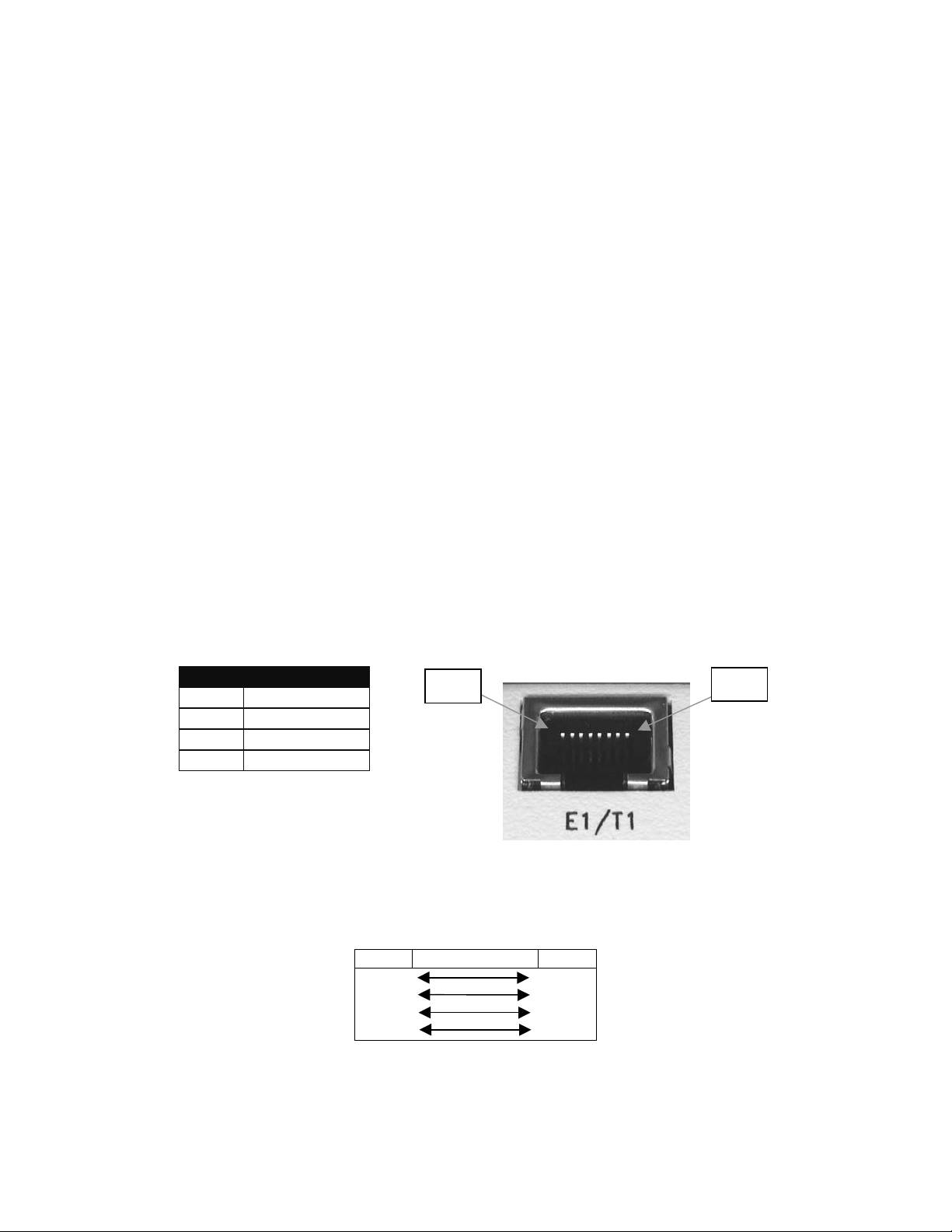
2.5.1 RJ-48 T1 * as a DCE Interface
PIN Direction
1 Tx (Output)
2 Tx (Output)
4 Rx (Input)
5 Rx (Input)
Figure 17. RJ-48 Cable Pin Out.
RJ-48 connector X-Over cable * for a DTE Interface:
PIN PIN
1 - Tx 4 - Rx
2 - Tx 5 - Rx
4 - Rx 1 - Tx
5 - Rx 2 - Tx
Pin 1
Pin 8
* Note: Any -RJ-48 Interface that is not labeled DCE is wired to accommodate DTE signals.
2-6
2361 Modem Users Manual
The EdgeAccess Universal Chassis System
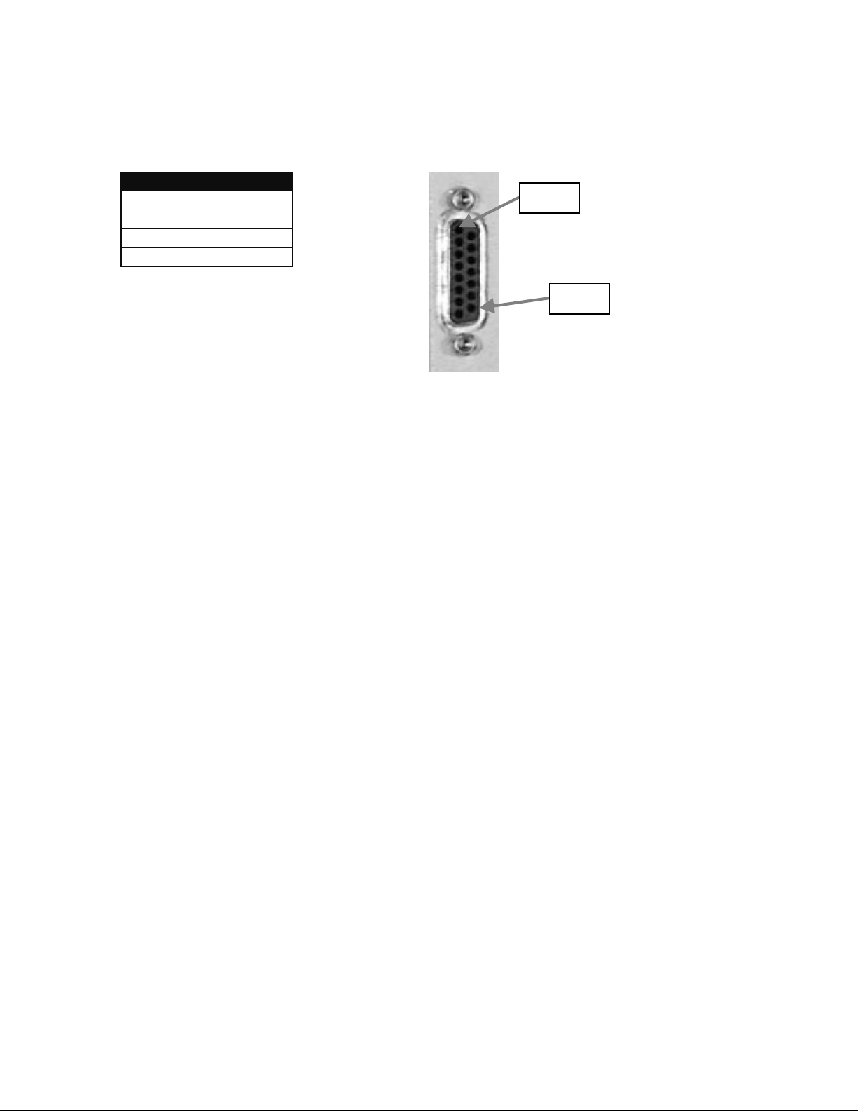
2.5.2 DA-15 Pin Out
DA-15 pin outs:
PIN Direction
1 Rx (Input)
9 Rx (Input)
3 Tx (Output)
11 Tx (Output)
Pin 1
Pin 15
Figure 18: DA-15 Pin Out.
2361 Modem Users Manual
2-7
 Loading...