

CANOGA PERKINS 2345 T3 User Manual

Model 2345
T3 Fiber Optic Modem
User Manual


EdgeAccess Universal Chassis System
CAUTION!
This product may contain a laser diode operating at a wavelength of 1300 nm - 1600 nm. Use of
optical instruments (e.g., collimating optics) with this product may increase eye hazard. Use of
controls or adjustments, or performing procedures other than those specified herein may result in
hazardous radiation exposure.
Under normal conditions, the radiation levels emitted by this product are under Class 1 limits in 21
CFR Chapter 1, Subchapter J.
ATTENCION!
Cet équipement peut avoir une diode laser émettant à des longueurs d'onde allant de 1300nm à
1600nm. L'utilisation d'instruments optiques (par exemple : un collimateur optique) avec cet
équipement peut s'avèrer dangereuse pour les yeux. Procéder à des contrôles, des ajustements ou toute
procédure autre que celles décrites ci-après peut provoquer une exposition dangereuse à des
radiations.
Sous des conditions normales, le niveau des radiations émises par cet équipement est en dessous des
limites prescrites dans CFR21, chapitre 1, sous chapitre J.
NOTICE!
This device contains static sensitive components. It should be handled only with proper ElectroStatic
Discharge (ESD) grounding procedures.
NOTE!
Cet équipement contient des composants sensibles aux décharges électro-statiques. Il doit absolument
être manipulé en respectant les règles de mise à la terre afin de prévenir de telles décharges.
Model 2345 User Manual

EdgeAccess Universal Chassis System
NOTICE
Canoga Perkins has prepared this users manual for use by customers and Canoga Perkins personnel as
a guide for the proper installation, operation and/or maintenance of Canoga Perkins equipment. The
drawings, specifications and information contained in this document are the property of Canoga
Perkins and any unauthorized use or disclosure of such drawings, specifications and information is
prohibited.
Canoga Perkins reserves the right to change or update the contents of this manual and to change the
specifications of its products at any time without prior notification. Every effort has been made to
keep the information in this document current and accurate as of the date of publication or revision.
However, no guarantee is given or implied that the document is error free or that is accurate with
regard to any specification.
Canoga Perkins Corporation
20600 Prairie Street
Chatsworth, California 91311-6008
Business Phone: (818) 718-6300
(Monday - Friday 7 a.m. - 5 p.m. Pacific Time)
FAX: (818) 718-6312 (24 hrs.)
Web Site: www.canoga.com
Email: fiber@canoga.com
Copyright © 2000 - 2005 Canoga Perkins Corporation
All Rights Reserved
EdgeAccess
Universal Chassis System
Model 2345
User Manual
Model Number 2345-UM
Product Number 6912470
Rev. L 01/2008
®
ii
Model 2345 User Manual

EdgeAccess Universal Chassis System
Table of Contents
Chapter 1 Overview.................................................................................................1-1
Chapter 2 Hardware Installation and Functions..................................................2-1
Setup and Installation..........................................................................................................................2-1
Power Up and Front Panel Functions..................................................................................................2-4
Alarms.................................................................................................................................................2-5
Chapter 3 Software Management...........................................................................3-1
Setting Up for Network Management .................................................................................................3-1
Set Up the Network Management Platform ..................................................................................3-1
Set Up the PC for Terminal Operation.........................................................................................3-1
Management User Interface ................................................................................................................3-2
General Screen Format.................................................................................................................3-2
User Interface Organization.........................................................................................................3-3
Login and Main Menu...................................................................................................................3-4
Manage the 2345.................................................................................................................................3-5
View the Hardware Setup .............................................................................................................3-5
Set the Date and Time...................................................................................................................3-5
Set Up SNMP Access ....................................................................................................................3-6
Manage Traps and Alarms............................................................................................................3-6
Set Up the Modem/SLIP/PPP Parameters....................................................................................3-8
Switch to PPP or SLIP Mode........................................................................................................3-8
Set the VT100 Rate........................................................................................................................3-9
Update Software ........................................................................................................................... 3-9
Manage Security................................................................................................................................3-10
Set Up Host Access .....................................................................................................................3-11
Change Your Password...............................................................................................................3-11
Manage the Modem...........................................................................................................................3-11
Set Up Functions and Check Status............................................................................................3-12
Set Up Redundancy.....................................................................................................................3-12
Monitor Data Transmission........................................................................................................3-13
Monitor Modem Performance.....................................................................................................3-14
Chapter 4 Maintenance and Troubleshooting ......................................................4-1
General Maintenance...........................................................................................................................4-1
Manage Cable Links..................................................................................................................... 4-1
Check Optical Power Levels.........................................................................................................4-1
Troubleshooting...................................................................................................................................4-2
Check a New Installation..............................................................................................................4-3
Set the Electrical Line Relay.........................................................................................................4-4
Run Loopback ...............................................................................................................................4-4
Chapter 5 Specifications..........................................................................................5-1
2345 Specifications .............................................................................................................................5-1
Model 2345 User Manual
iii

EdgeAccess Universal Chassis System
2345 Models........................................................................................................................................5-2
Appendix A Warranty Information......................................................................A-1
Appendix B Acronyms and Abbreviations........................................................... B-1
Index .........................................................................................................................5-1
List of Figures
Figure 1. Rackmount 2345................................................................................................................. 1-2
Figure 2. Standalone 2345, Front and Rear Panels............................................................................1-2
Figure 3. Jumper and Switch Locations ............................................................................................. 2-2
Figure 4. General Screen Format.......................................................................................................3-3
Figure 5. Normal Operation...............................................................................................................4-5
Figure 6. Local Loopback.................................................................................................................. 4-5
Figure 7. Local Bidirectional Loopback............................................................................................ 4-5
Figure 8. Local Loopback at Both Ends ............................................................................................4-5
Figure 9. Remote Loopback............................................................................................................... 4-6
Figure 10. Remote Bidirectional Loopback.......................................................................................4-6
List of Tables
Table 1. Jumper Settings....................................................................................................................2-1
Table 2. EIA-232 Pinout.................................................................................................................... 2-3
Table 3. 2345 LED Functions............................................................................................................ 2-4
Table 4. Main Menu Selections ......................................................................................................... 3-4
Table 5. Hardware Configuration Report ..........................................................................................3-5
Table 6. SNMP Configuration Options..............................................................................................3-6
Table 7. Trap Configuration Options.................................................................................................3-7
Table 8. Alarm Configuration Options.............................................................................................. 3-7
iv
Model 2345 User Manual

EdgeAccess Universal Chassis System
Chapter 1
Overview
The Model 2345 managed T3 fiber optic modem with Optical Line Interface Module (OLIM) extends
T3 (44.736 Mbps) signals between devices located up to 120 Km apart. The OLIM supports
multimode and single mode fiber. Use the modem to extend a PBX, router, video codec, DS3
multiplexer, or ATM switch.
The 2345 transports B3ZS or AMI coded data. The 2345 supports both framed and unframed modes.
Framed mode supports C-bit Parity or M-13 framing patterns, can correct polarity errors, and gathers
DS3 statistics. Unframed mode passes data with full transparency.
The 2345 can be used in a UCS 1000 or UCS 1001 chassis or directly as a standalone.
• The UCS 1000 Chassis can hold up to 15 model 2345 modems; you can manage each 2345 either
directly through the serial port or through the Domain Management Module (DMM) within the
domain.
Note: The Chassis Interconnect Module (CIM) must be present in the UCS 1000 chassis in order
for the DMM to recognize the 2345 modules.
• The UCS 1001 Chassis can hold up to two model 2345 modems; you can manage each 2345
directly through the serial port.
• The standalone 2345 provides one modem that you can manage directly through the serial port.
The 2345 is hot swappable; you can insert or remove it at any time without disrupting the data
transfer of other modules in the chassis.
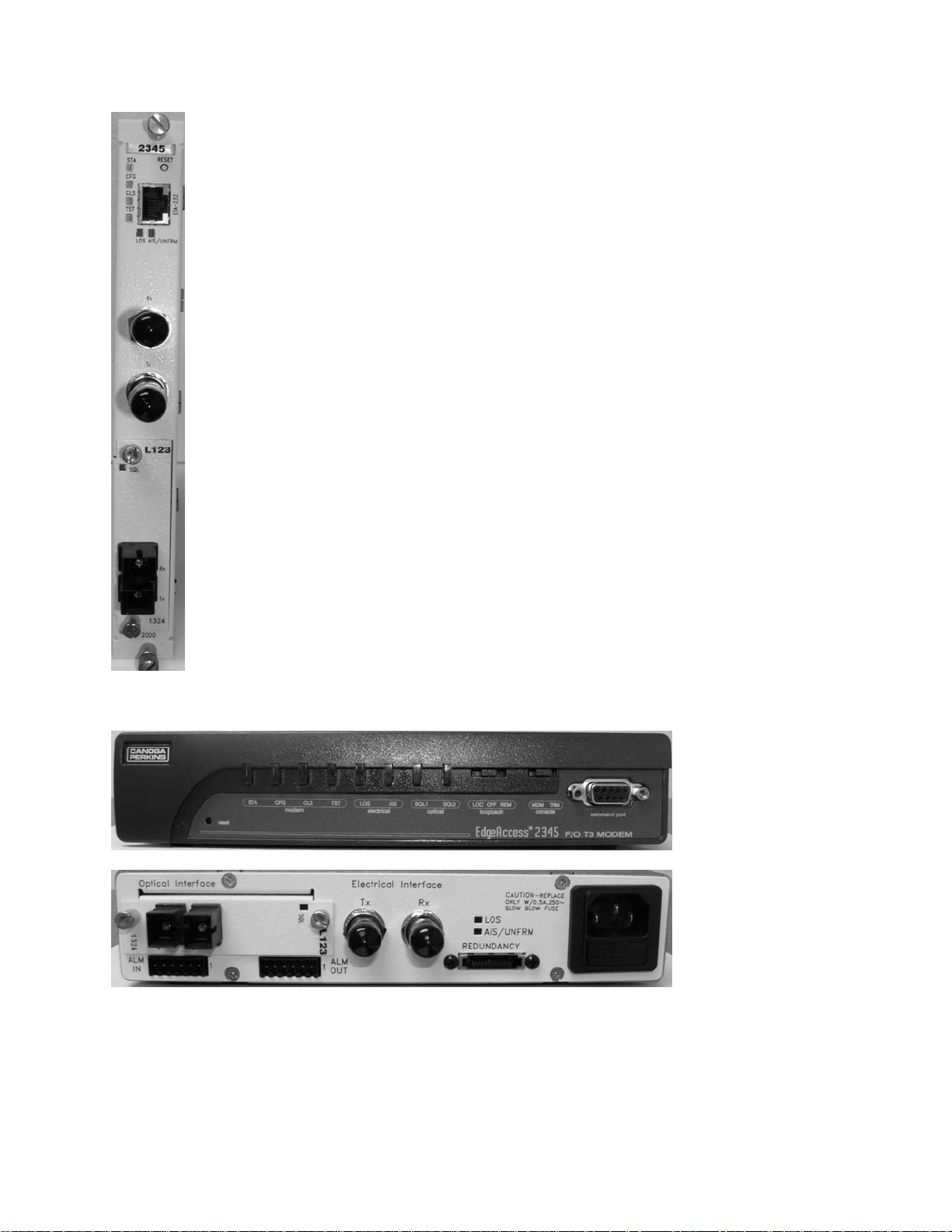
The rackmount 2345 front panel, shown in Figure 1, includes:
• EIA-232, BNC, and optical connectors
• Reset switch
• LEDs for:
• System Status (STA)
• Configuration (CFG)
• Composite Loss of Signal (CLS)
• Test/Loopback (TST)
• Electrical Loss of Signal (LOS)
• Alarm/Unframed Data (AIS/UNFRMED)
The front and back panels on the standalone 2345, shown in Figure 2, include the same connectors,
switch, and LEDs, with these additional items:
• Alarm In and Out connectors
• Serial port
• MDM/TRM and Loopback switches
Model 2345 User Manual
1-1
EdgeAccess Universal Chassis System
Figure 1. Rackmount 2345
Figure 2. Standalone 2345, Front and Rear Panels
1-2
Model 2345 User Manual

EdgeAccess Universal Chassis System
The 2345 supports both full modem redundancy, with two modems, and fiber redundancy, through
dual-path OLIMs. You can enable automatic or manual redundancy or disable the option.
Dual-path modules provide redundancy for the fiber link. The two transmit (Tx) outputs and two
receive (Rx) inputs are connected on different fiber. Both Tx output transmit the same data; one Rx is
active and the other is inactive. If data is lost on the active Rx, the module switches automatically to
the inactive Rx and you can troubleshoot while data transmission continues.
When the redundant mode is set to Auto and the link fails, the software logs an alarm and switches to
the secondary link. If the redundancy mode is set to Manual and the link fails, the software logs the
alarm, but does not switch to the secondary link.
For details on setting up the hardware for redundancy, see Chapter 2. For details on setting up the
software, see "Set Up Redundancy" on page 3-12.
Model 2345 User Manual
1-3

EdgeAccess Universal Chassis System
1-4
Model 2345 User Manual

EdgeAccess Universal Chassis System
Chapter 2
Hardware Installation and Functions
You can install the 2345 in a UCS 1000 or 1001 or place a standalone 2345 in a flat, secure location.
Before starting to install the 2345 in a chassis, make sure the chassis is installed and its User Manual
is available for reference. If the system includes an optional DMM and CIM(s), make sure these are
available:
• Serial cable (required to connect to a VT100 type terminal or PC)
• VT100 type terminal or PC to run the User Interface Manager software
• The DMM and CIM manuals
Setup and Installation
Follow these guidelines to determine which slot(s) can hold the 2345:
• You can install the 2345 in a UCS 1000 in any slot except 0 ( reserved for the DMM and CIM) or
the power supply slot(s).
• You can install the 2345 in a UCS 1001 in either slot.
• If this is a redundant pair of 2345s, plan to install the primary modem in an odd-numbered slot
and install the secondary modem in the next higher-numbered slot, such as slots 3 (primary) and 4
(secondary) or in a UCS 1001, left (primary) and right (secondary).
1. Unpack and inspect all components. Save the shipping carton and packing materials in case you
need to return the equipment to the manufacturer. Appendix A provides information for Return
Material Authorization (RMA).
2. If this is a standalone 2345, remove four screws from the back panel and slide the board part of
the way out to access the switch and jumpers.
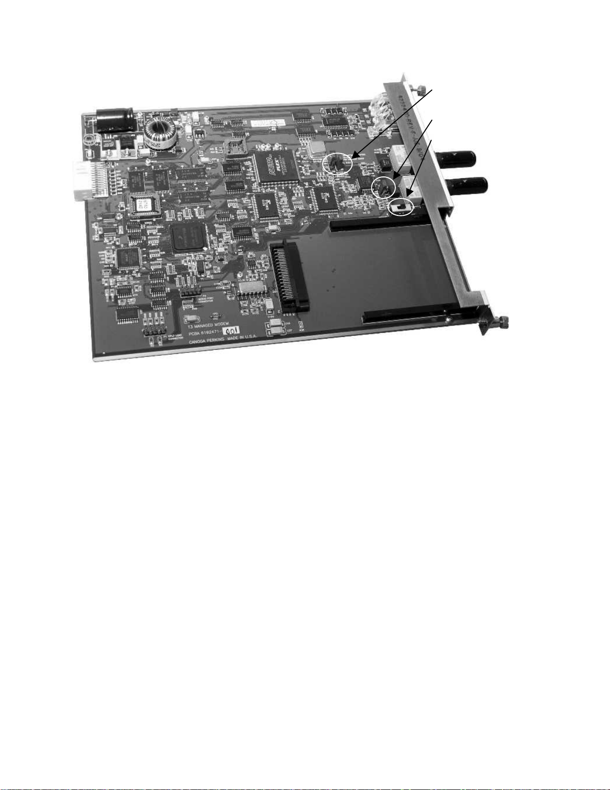
3. Set jumpers as needed for
Figure 3.
Table 1. Jumper Settings
Jumper Position Description
W2/W3 W2 Not Used
W3 LBO more than 300 ft (90 m)
Off LBO 300 ft (90 m) or less
W4/W5 W4 Allows software control of loopback; default
W5 Not used
Off Sets loopback
W6/W7 W6 Normal pulse (NP); default
W7 Wide pulse (WP)
line buildout (LBO), loopback, and pulse width; see Table 1 and
Model 2345 User Manual
2-1
EdgeAccess Universal Chassis System
W2/W3,
W4/W5
W6/W7
SW3
Figure 3. Jumper and Switch Locations
4. Set SW3: for Framed Data, set it toward the BNC connectors; or for Unframed data, set it away
from the BNC connectors.
5. If this is a standalone 2345, slide the board back in, being careful to align the switches in the front
panel, then replace the four screws in the back panel.
6. Slide the rackmount 2345 into the slot in the chassis or place the standalone 2345 on a flat, secure
surface, then slide the OLIM into the 2345, and tighten all captive screws.
Note: The 2345 is hot-swappable and can be inserted or removed without disrupting data transfer
in other modules in the chassis.
7. If this is a standalone 2345, see Figure 2 and connect the alarm outputs:
• At ALM OUT, on the rear panel, connect devices to receive alarm information.
• NO The contacts are open for normal operation and closed in a fault condition
• COM The electrical common
• NC The contacts are closed for normal operation and open in a fault condition
• At ALM IN, on the rear panel, connect devices to supply alarm information. Connect cabling
from the + output on the device to MAJ or MIN_IN+, from the - output to MAJ or MIN_IN-, and
from ground on the device to CH_GND on the standalone.
2-2
Model 2345 User Manual

EdgeAccess Universal Chassis System
8. Connect the power:
• If this is a rackmount 2345, the module receives power automatically from the chassis. For
details, see the user manual for the chassis.
• If this is a standalone 2345, see Figure 2 and connect the power at the back panel:
• For AC power, plug the power cord into the socket on the 2345; to turn off power, unplug the
power cord.
• For a DC supply, loosen the screws for the GND and -48 VDC terminals, then slide the wires
under the square washers, and tighten the screws. Use an ohmmeter to verify that -48 VDC is
not shorted to GND, then connect the power cables to the power source.
The 2345 uses electrical cables to connect to the local site and fiber optic cables to connect to the
remote modem. Follow these steps to connect the electrical and optical cables:
9. If you will manage the 2345 directly, rather than through a DMM, plug a serial cable into the
EIA-232 port. For the pinout, see Table 2.
Table 2. EIA-232 Pinout
Pin Number Signal Name Source I/O
1 RI DCE Output
2 DCD DCE Output
3 DTR DCE Input
4 SIG GND
5 RXD DCE Output
6 TXD DCE Input
7 CTS DCE Output
8 RTS DCE Input
10. To connect to T3 at the local site, follow either of these steps:
• For a non-redundant modem, plug the BNC cables from the local equipment into the Rx and
Tx connectors using Tx to Rx, and Rx to Tx orientation.
• For fully-redundant modems, use Canoga Perkins Y-cables p/n C002-000. Plug the single
end of a Y cable into Rx on the local equipment and plug each dual end into Tx on the
modems. Plug the single end of another Y cable into Tx on the local equipment and plug
each dual end into Rx the modems.
11. To connect a local pair of fully-redundant standalone modes, plug Canoga Perkins cable p/n
C001-000 into the Redundancy connectors located at the lower center of the rear panels.
Dirty optical connectors are a common source of link loss or attenuation problems, especially for
single mode fiber (SMF). Clean the connectors before plugging in a cable and whenever there is a
significant or unexplained light loss. To prevent contamination, always install protective dust covers
on unused fiber optic connectors.
12. Wipe the ferrule and the end-face surface of the male fiber coupler with a lint-free isopropyl
alcohol pad from a fiber cleaning kit.
Model 2345 User Manual
2-3

EdgeAccess Universal Chassis System
13. Use canned air to blow out any dust from the female fiber coupler.
Caution: To avoid damaging the fiber end-surface or connector, use extreme care when
installing or removing cables.
14. Plug in the optical cables with Tx to Rx, and Rx to Tx orientation. For redundancy, use primary
to primary and secondary to secondary orientation.
15. Label each cable and connector with the signal name and direction.
16. For cable connections to other modules in the chassis, see the appropriate user manual for details.
Canoga Perkins recommends that you determine and record link attenuation and transmission power
before starting normal link traffic. The attenuation factor and transmission power identify potential
problems with links near the lower limit of receiver limitations.
For details on link attenuation and transmission power, see Chapter 5.
Power Up and Front Panel Functions
During the initial power-up sequence, all LEDs light amber. When start-up is complete, the setup and
installation are correct, and data is transmitting normally across the link, the STA LED lights green
and the CFG, TST, LOS, and CLS LEDs are off. During normal operation, the LED colors change
according to system and port conditions. The STA, CFG, and TST LEDs show the module condition.
The LOS and CLS LEDs show the electrical and optical signal conditions. Table 3 shows the LED
states for various conditions.
Table 3. 2345 LED Functions
LED Status Indicates
STA Off Power off or fault
Green Normal operation; active modem
Amber Normal operation; inactive redundant modem
Amber blinking System self test
Red Modem fault
CFG Off Normal operation
Red Conflict in configuration
CLS Off Normal operation
Red Local composite loss of sync
Red blinking Remote composite loss of sync
TST Off Normal operation
Amber Local modem in loopback
Amber blinking Remote modem in loopback
2-4
Model 2345 User Manual
 Loading...