

Cannondale LEFTY MAX 140 Owner's Manual

WARNING
READ THIS SUPPLEMENT AND YOUR
CANNONDALE BICYCLE OWNER’S MANUAL.
Both contain important safety information.
Keep both for future reference.
2010
LEFTY MAX 140
125123.PDF
In this supplement, particularly important information is presented in the following ways:
WARNING
Indicates a hazardous situation which, if not
avoided, could result in death or serious injury.
NOTICE
Indicates special precautions that must be taken to
avoid damage.
TIP
A TIP provides helpful information.
This manual meets EN standards
14764, 14766, and 14781.
Vélo certifié conforme aux exigences du décret
N 95-937 du 24 août 1995 norme NFR030
2010 LEFTY MAX 140
Owner’s Manual Supplement
125123.PDF
EN - 07/09
Please note that the specications and information in this manual are subject to change for product
improvement. For the latest product information, go to http://www.cannondale.com/tech_center/
Replacement Cannondale part numbers are shown
throughout this supplement in BOLD ITALIC text.
CONTENTS
SAFETY INFORMATION ......................................2
INTENDED FORK USE ................................................ 2
FORK DAMAGE ......................................................... 3
SPECIFICATION .................................................4
LEFTY MAX 140 w/ FOX RLC ..................................... 4
LEFTY MAX 140 w/ PBR ........................................... 4
LEFTY WHEEL HUB................................................... 4
FRONT WHEEL ..................................................6
1 1/8” STEERER ADAPTER...................................8
XC3 STEMSTEERER .........................................10
MAINTENANCE SCHEDULE ...............................12
CLEANING ............................................................. 13
FRAME BUMPER ................................................... 13
BOOT INSPECTION ................................................ 14
CLEAN/REOIL AIR FILTER .................................... 15
NEEDLE BEARING RESET....................................... 16
CLEAN/REGREASE TELESCOPE ............................ 18
LEFTY MAX 140 W/ FOX RLC.................................
ADJUSTMENTS ..................................................... 19
SAG/PRELOAD ...................................................... 22
NEEDLE BEARING RESET....................................... 23
SPRING CHANGE ................................................... 24
OIL CHANGE.......................................................... 26
LEFTY MAX 140 W/ PBR ......................................
ADJUSTMENTS ..................................................... 28
RECOMMENDED AIR PRESSURE ........................... 29
NEEDLE BEARING RESET....................................... 30
REPLACEMENT PARTS .....................................31
WARNING
This supplement may include procedures beyond the scope of general mechanical aptitude. Special tools, skills, and knowledge may be
required. Improper mechanical work increases the risk of an accident. Any bicycle accident has risk of serious injury, paralysis or death.
To minimize risk we strongly recommend that owners always have mechanical work done by an authorized Cannondale retailer.
2
SAFETY INFORMATION
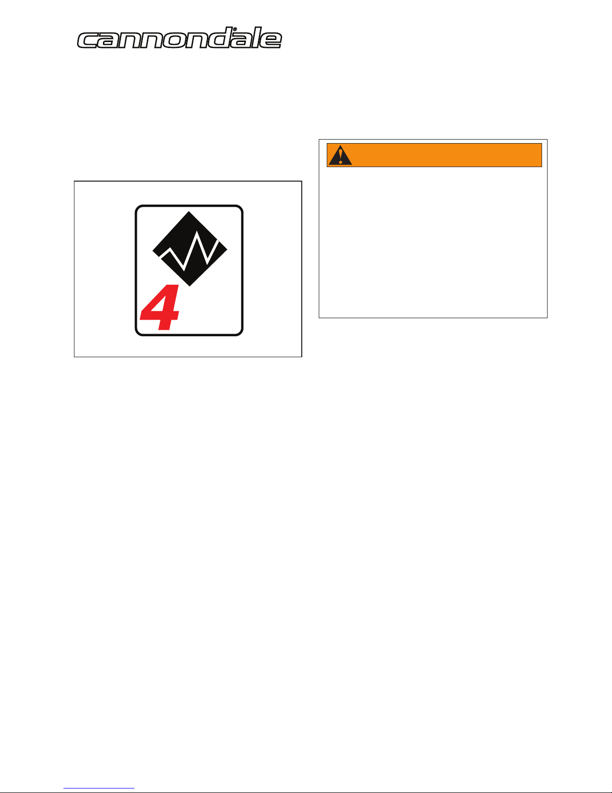
INTENDED FORK USE
Lefty MAX 140mm forks are intended for use in Condition 4
(All Mountain) riding. The CONDITION 4 symbol is shown next
gure.
For riding on
rough trails
with medium
obstacles
Figure 1.
CONDITION 4
Bikes designed for riding Conditions 1, 2, and 3, plus rough
technical areas, moderately sized obstacles, and small jumps.
Fork is Intended
For trail and uphill riding. All-Mountain bicycles are: (1)
more heavy duty than cross country bikes, but less heavy
duty than Freeride bikes, (2) lighter and more nimble than
Freeride bikes, (3) heavier and have more suspension travel
than a cross country bike, allowing them to be ridden in more
dicult terrain, over larger obstacles and moderate jumps, (4)
intermediate in suspension travel and use components that t
the intermediate intended use, (5) cover a fairly wide range of
intended use, and within this range are models that are more
or less heavy duty. Talk to your retailer about your needs and
these models.
Fork Not Intended
This fork is not intended for use in extreme forms of jumping/
riding such as hardcore mountain, Freeriding, Downhill, North
Shore, Dirt Jumping, Slope-style, Hucking etc.
WARNING
UNDERSTAND YOUR FORK AND ITS INTENDED USE.
USING YOUR FORK THE WRONG WAY IS DANGEROUS.
Industry usage Conditions 1 - 5 are generalized and
evolving. Consult your Cannondale Dealer about how you
intend to use your bike.
Please read your Cannondale Bicycle Owner’s Manual
for more information about Intended Use and
Conditions 1-5.

125123.PDF
3
FORK DAMAGE
WARNING
STOP RIDING A DAMAGED FORK IMMEDIATELY.
The following conditions indicate that serious fork damage is present:
1. Any unusual “klunking” or knocking noises.
2. A change in fork travel.
3. An over-extended, elongated, or compressed boot.
4. Changes from the way the fork had been working
5. Loss of adjustment features, oil leaks, or air leaks.
6. Crash or impact damage (deep scratches, gouges, dents, or bending)
7. Small cracks under the bolt head of upper and lower clamp bolts. This inspection requires the removal of the bolts.
Horizontal cracks above and below the intersection of the upper and lower clamps with the outer tube portion of the
Lefty carbon structure.
Vertical cracks in the outer tube (where the races and needle bearings run). These may show as long, straight lines
perhaps several lines parallel to each other.
Also, please read Inspect For Safety in PART II, Section D. of your Cannondale Bicycle Owner’s Manual.
HAVE ANY DAMAGED FORK INSPECTED AND DAMAGE REPAIRED BY YOUR CANNONDALE DEALER. YOU CAN BE
SEVERELY INJURED, PARALYZED OR KILLED IN AN ACCIDENT IF YOU IGNORE THIS WARNING.
The MAINTENANCE section of this supplement includes information about regular maintenance practices that can keep your fork
in good operating condition.
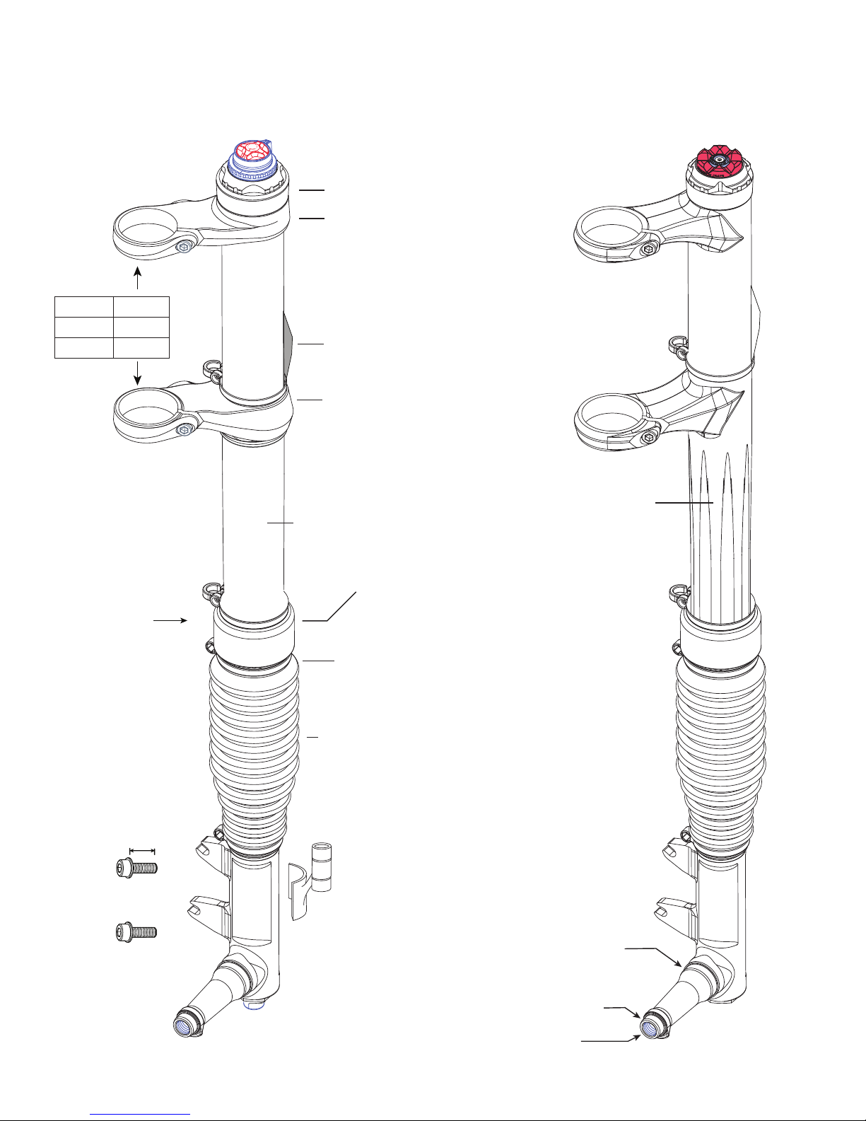
SERIAL NUMBER
Located on outertube
under the air lter
foam element.
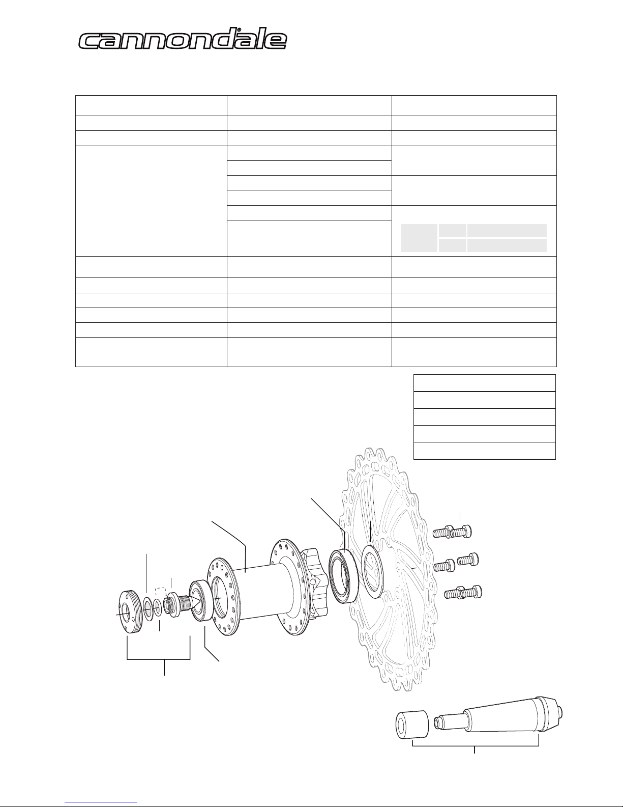
International Standard
BRAKE CALIPER MOUNTS
CALIPER MOUNTING BOLTS
CAP
Park SPA-1
AXLE BOLT
SEAL
INNER BEARING
WHEEL HUB
OUTER BEARING
WASHER
O-RING
NO RIDE
WHEEL TRUING TOOL - QCTL108/
15.0 Nm
DISC ROTOR BOLTS
6.2 Nm, Loctite 262
LEFTY WHEEL HUB
(exploded view)
QC117/
KB61902/
KB61805/
QC118/
QC081/
(24 spk, 6bolt)
QC627/
(32 spk, 6bolt)
WIDTHHT
137.6 mm 4.5”
163.0 mm 5.5”
SPECIFICATION
LEFTY MAX 140 w/ FOX RLC LEFTY MAX 140 w/ PBR
TRAVEL 140 mm 140 mm
INTENDED USE CONDITION 4, All Mountain CONDITION 4, All Mountain
ADJUSTMENTS
LOCKOUT
POP-TOP
REBOUND
LOW-SPEED COMPRESSION
REBOUND
BLOW-OFF THRESHOLD
MAIN SPRING AIR PRESSURE
LIMITS:
MIN. 50 psi, 3.4 bar
MAX. 225 psi, 15.5 bar
SPRING PRELOAD
10mm/10 turns MAX.
RECOMMENDED SAG 25-30% 35 - 42 mm 35 - 42 mm
SPRING TYPE/MATERIAL COIL/STEEL SOLO AIR
NEGATIVE SPRING STEEL AIR AUTOMATIC
DAMPER OIL VOLUME 145cc --
DAMPER OIL WEIGHT 10W 5W
TELESCOPE LENGTH
(Needle Bearing Reset)
720 - 730 mm 720 - 730 mm
LEFTY 24 AND 32 SPOKE HUB DIMENSIONS
DISC FLANGE DIAMETER 58MM
NON DISC FLANGE DIAMETER 44.5MM
DISC FLANGE TO CENTER 35MM
NON DISC FLANGE TO CENTER 20MM
125123.PDF
5
SERIAL NUMBER
Located on outertube
under the air lter
foam element.
CLAMP BOLT
16mm
ONE-PIECE INTEGRATION (O. P.I.)
INNER TUBE/SPINDLE
AIR FILTER ASSEMBLY
HD209/BLK
CARBON
(FOX RLC shown)
OUTER COLLAR
International Standard
BRAKE CALIPER MOUNTS
ADJUSTMENT
PBR - AIR PRESSURE
RLC - BLOW- OFF THRESHOLD
ALLOY
(PBR shown)
9 Nm, 80 In Lbs
CLAMP KIT
HD011/
AXLE BOLT THREADS
OUTER HUB BEARING LAND
INNER HUB BEARING LAND
SENSOR MOUNT
8CM01/BLK
LEFTYBOLTS/
CALIPER MOUNTING BOLTS
UPPER CLAMP
LOWER CLAMP
INTEGRATED 3D FORGED
OUTER TUBE
UPPER /LOWER CLAMPS
CARBON OUTER TUBE
WIDTHHT
137.6 mm 4.5”
163.0 mm 5.5”
BOOT
KF222/
FRAME BUMPER
HD215/
9 Nm, 80 In Lbs
9 Nm, 80 In Lbs
9 Nm, 80 In Lbs
KH057/
Thread repair kit

6
FRONT WHEEL
REMOVAL
1 Loosen the brake caliper mounting bolts.
Tilt the lower caliper bolt out of the boss so the caliper is
up out of the way of the disc. Snug up on the upper bolt
to hold caliper in place.
Take note of brake alignment shims between brake
bosses and the caliper. Be sure to reposition correctly.
2. Turn the hub extraction bolt counter-clockwise (ccw) to
remove the wheel.
NOTICE
■ Make sure the bolt is completely disengaged
before attempting to remove the wheel. Never
try to pull the wheel o forcefully.
■ When the wheel is o, to keep dirt out, cover the
hub opening.
■ Protect spindle from damage when wheel is
removed.
Continue turning the bolt until the wheel can be
removed easily from the spindle.
1
5mm
cw
ccw
125123.PDF
7
INSTALLATION
1. Inspect inside the wheel hub for contamination and
the condition of the hub seal. Take corrective action if
necessary.
Wipe the spindle clean with a dry shop towel and apply a
high-quality bike grease to the spindle bearing lands and
end threads.
2. Slide the wheel straight onto the spindle so, the larger
hub bearing starts to position on it spindle seat. At this
point, the axle bolt threads can correctly engage the
threaded spindle if the wheel is held on straight.
NOTE: Install the front wheel by positioning the bike
horizontally with the spindle facing up. Then place the hub
straight down onto the spindle, and tighten the axle bolt.
3. When the axle bolt threads engage the spindle, turn the
bolt clockwise with nger force slowly to allow the hub
bearings to slide onto the spindle bearing seats.
Once the hub has been drawn onto the hub completely,
use torque wrench to tighten to nal 15.0 N•m (133.0
In•Lbs).
4. Reinstall the brake caliper. Tighten bolts to 78.0 In•Lbf
(9.0 N•m).
5. Spin the wheel to make sure it moves freely. Be sure to
test the brakes for proper operation before riding.
WARNING
DO NOT CONTAMINATE BRAKE CALIPER, PADS, OR
ROTOR WITH GREASE.
WARNING
DO NOT RIDE WITHOUT A PROPERLY MOUNTED,
ADJUSTED, AND FUNCTIONING FRONT BRAKE
SYSTEM.
The Lefty (disc/caliper) acts as an integral secondary
wheel retention system. If the system is missing or
improperly installed, or if the wheel hub axle bolt should
loosen, the front wheel could slide o the spindle end.
When mounting IS compatible brake systems:
Follow brake manufacturer’s instructions when mounting
the brake caliper to the spindle brake bosses. Do not
modify the fork in any way.
PLEASE ASK YOUR CANNONDALE DEALER FOR HELP
WHEN INSTALLING COMPATIBLE FRONT BRAKE
SYSTEMS.
NOTICE
■ LOCATE BRAKE ROTOR BETWEEN THE PADS.
Replace shims that are in use, be sure the shims are
positioned between the caliper (adapter if any) and
inner face of the fork mounts, not under the head of
the caliper bolts.
■ USE ONLY THE LEFTY 16mm CALIPER BOLTS TO
MOUNT THE BRAKE. Longer bolts can result in
contact with the brake rotor causing severe damage.
Check clearance between the bolt tips and rotor after
remounting the caliper. Order replacement bolts Cannondale p/n LEFTYBOLTS/.
■ MAKE SURE THE BRAKE DISC CAN NOT MAKE
CONTACT WITH THE FORK BOOT. A rotating brake
disc can wear through the boot allowing contaminants
into the fork.

8
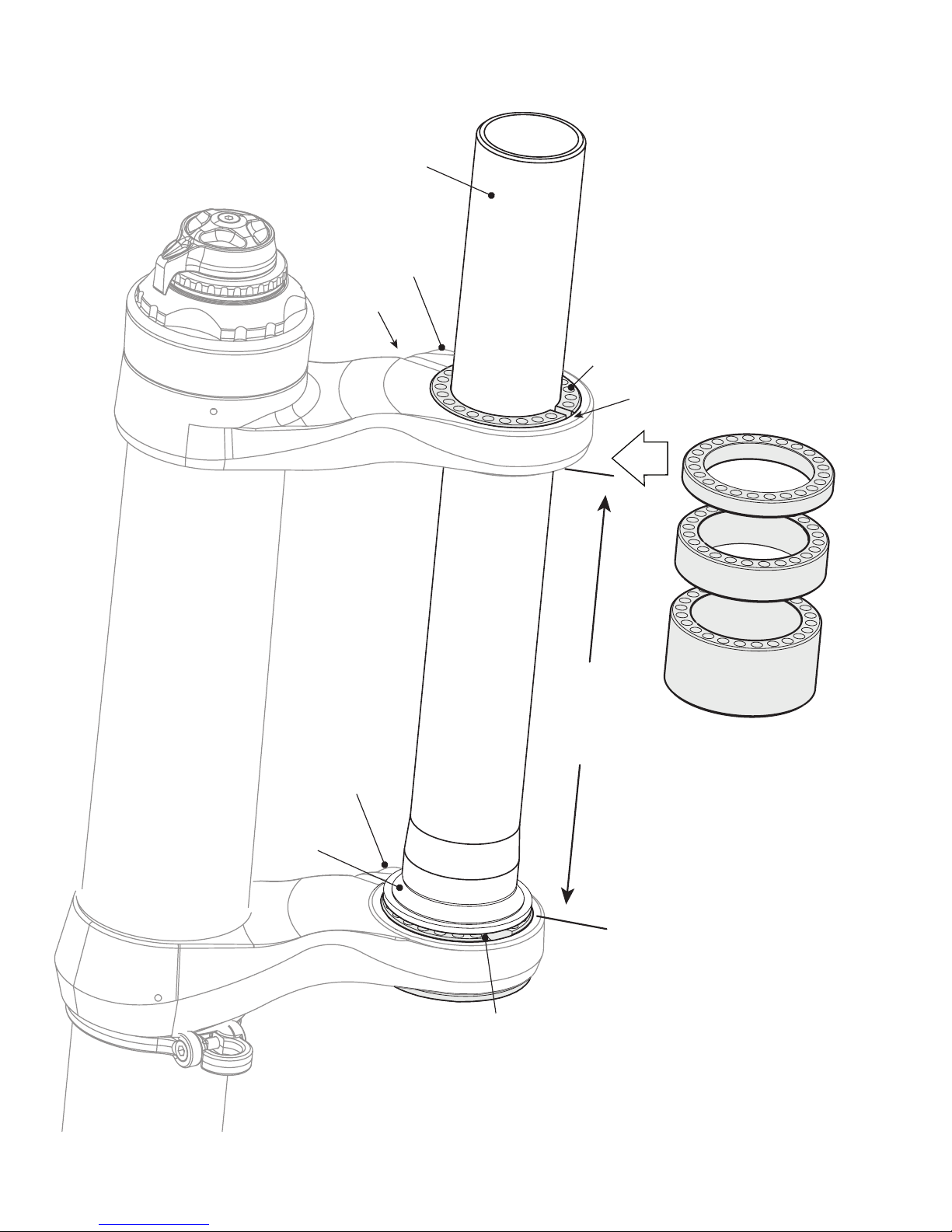
(A Headset part)
1.125 in STEERER ADAPTER
The 1.125 in steerer adapter assembly enables fork installation into a standard 1.125 head tube. Consult the table on the next
page to determine if the 1.125 steerer adapter system is compatible with the 1.125 head tube before attempting to install the
fork. The adapter system only be installed by a professional bike mechanic.
INSTALLATION POINTS
• When installing the steerer into the headtube with the Lefty, make sure the lower reducer is inserted completely into the
lower clamp.
• Install the upper reducer so that the top is ush with top of upper clamp or raised slightly. Do not install upper reducer with
the top below the below the top of the upper clamp.
• Locate the upper reducer slot 180° opposite the Lefty upper clamp slot.
• Install a combination of adapter kit spacers (5 mm, 10 mm, and 20 mm) to close the gap between the headset top cap and
the upper reducer.
• Install all handlebar stem spacers above the upper reducer.
• Tighten the upper and lower Lefty Clamp bolts AFTER the stem top cap has been installed and preload set. Tighten the Lefty
Clamp bolts to 9 Nm, 80 In Lbs.
MAXIMUM 1.125 HEADTUBE LENGTH (mm)
CANNONDALE KIT 1.125 HEADSET If (A) = 137.7 mm If (A) = 163.0 mm
KH058/ Kit, Steerer,Lefty 1 1/8” w/ Standard Headset 112.3 mm 137.7 mm
KH059/ Kit, Steerer,Lefty 1 1/8” w/ Hiddenset Headset 124.3 mm 149.7 mm
KH060/ Kit, Steerer,Lefty 1 1/8” w/ Zero Stack Headset 127.1 mm 152.5 mm
125123.PDF
9
20 mm
CROWN RACE
(A Headset part)
(A)
CLAMP WIDTH
UPPER REDUCER
Slot
Slot
LOWER REDUCER
1.125 in STEERER
SPACERS
10 mm
5 mm
CLAMP BOLTS
9 Nm, 80 In Lbs
CLAMP BOLT
9 Nm, 80 In Lbs
 Loading...