

Cannondale Lefty MAX, Lefty Jake Owner's Manual
2:1(560$18$/6833/(0(17
/HIW\0$;/HIW\-DNH
31
READ THIS MANUAL CAREFULLY!
It contains important safety information.
IMPORTANT MANUAL INFORMATION
DANGER
CAUTION :
NOTE:
FAILURE TO FOLLOW THE WARNINGS CONTAINED IN THIS MANUAL CAN RESULT IN SERIOUS INJURY OR DEATH.
Information important to your safety is distinguished in this manual by the following notations:
The safety alert symbol means......
“ATTENTION! BECOME ALERT! YOUR SAFETY IS
INVOLVED.”
Indicates that DEATH or severe injury WILL result if the
instructions are not followed.
WARNING
Indicates a pote ntial haz ard that co uld resu lt in serio us
injury or death.
A CAUTION indicates that special precautions must be
taken to avoid damage to the machine.
A NOTE provides helpful information intended to make
maintenance easier or the instructions presented clearer.
2

CONTENTS
Compression Damping Assembly . . . . 22
website. Go to: http://www.cannondale.com/bikes/
tech/manuals.html
About this Ow ner’s Manual Supp lement 3
Safety Information . . . . . . . . . . . . . . . . . 3
Product Features . . . . . . . . . . . . . . . . . 4
Lefty MAX TPC+ . . . . . . . . . . . . . . . . . . 4
Lefty Jake. . . . . . . . . . . . . . . . . . . . . . . . 4
Fork Pre-Ride Checklist. . . . . . . . . . . . 5
Fork Setup . . . . . . . . . . . . . . . . . . . . . . 6
Cable & Line Routing. . . . . . . . . . . . . . . 6
Front Wheel . . . . . . . . . . . . . . . . . . . . . . 7
Computer Mounting . . . . . . . . . . . . . . . . 9
Tuning. . . . . . . . . . . . . . . . . . . . . . . . . 10
Sag. . . . . . . . . . . . . . . . . . . . . . . . . . . . 10
Fork Spring. . . . . . . . . . . . . . . . . . . . . . 11
Spring Kits . . . . . . . . . . . . . . . . . . . . . . 11
Compression Damping. . . . . . . . . . . . . 11
Rebound Damping. . . . . . . . . . . . . . . . 12
Maintenance . . . . . . . . . . . . . . . . . . . . 12
Required Tools. . . . . . . . . . . . . . . . . . . 12
Schedule . . . . . . . . . . . . . . . . . . . . . . . 13
Mechanical Adjustments. . . . . . . . . . 14
Changing the fork oil . . . . . . . . . . . . . . 15
Fork Removal. . . . . . . . . . . . . . . . . . . . 16
Fork installation . . . . . . . . . . . . . . . . . . 16
Changing the fork spring . . . . . . . . . . . 17
Checking needle bearing migration . . . 18
Cleaning . . . . . . . . . . . . . . . . . . . . . . . 19
Illustrations. . . . . . . . . . . . . . . . . . . . . 20
Tire Size / Clearance . . . . . . . . . . . . . . 20
Rebound Damping Assembl y. . . . . . . . 21
ABOUT THIS OWNER’S MANUAL SUPPLEMENT
This manual adds important safety, maintenance,
and proper use information to your Cannondale
Owner’s Manual for Multi-speed Bicycles.
This supplement does not replace your owner’s
manual.
It is important to your safety to read your owner ’s
manual and all the owner’s manual supplements for
your particular bike and components.
You should ha ve recei ved the Cannondal e Owne r’s
Manual for Multi-speed Bicycles all applicable supplements from your dealer when you purchased your
new bike.
If you did not receive an owner ’s manual a nd the
supplements for it, or are not sure what supplements
you should have received with your bike please call
your Cannondale dealer immediately, or call us at
one of the telephone numbers listed on the back
cover of this manual.
Do not ride your new bicycle until you have
received and read the owner’s manual and all
supplements for your particular bicycle.
Keep this supplement with your owner’s manual.
Adobe PDF versions of the Ca nnondal e Owner ’s
Manual for Multi-speed Bicycles and any su pplement can be downloaded free of charge from our
SAFETY INFORMATION
WARNING
POTENTIAL HAZARD
Riding high performance bicycles and suspen sion systems beyond your skills and abilities
WHAT CAN HAPPEN
Advanced bicycle suspension systems can
increase the handling and stability of most
high-performance bicycles.
You could have a bad accident if your skill is
not up to handling an advanced suspension. If
you lack the skills and experience necessary to
travel at higher speeds and maneuver over difficult terrain at the greatly increased performance level, you can travel faster than your
abilities. You can lose control of the bike in
these conditions and crash. Anytime you lose
control of the bike, especially at high speed
and in advanced ter rain, you risk severe injur y
or death in a crash.
HOW TO AVOID THE HAZARD
Ride at reduced speeds.
Learn the performance characteristics of your
bike and suspension components before trying
any downhill or very fast biking.
Ride within your skills and abilities.
T ake a bicycle training course.
3

WARNING
POTENTIAL HAZARD
Riding on a damaged fork
WHAT CAN HAPPEN
If the suspension fork ever begins to...
1. Make “knocking” or “clunking noises
2. Show unexplained increase in travel,
3. Increase in fork extension or travel
4. A sudden loss of lock out ability on
equipped forks.
5. Or, a sudden loss of adjustment features
... continued use can result in a separation of
the fork from the bicycle frame. You can be
severely injured or killed in an accident.
HOW TO AVOID THE HAZARD
If you observe any of the above, DO NOT RIDE.
Take the fork to an Authorized Cannondale
Dealer to have it inspected and serviced.
PRODUCT FEATURES
LEFTY MAX TPC+
• Manitou TPC+ damping with External
Compression and Clicker Rebound Adjustment.
• Internal Pre-load Adjustment
• Titanium Coil Spring
• Golden Spectro Cartridge Fork Fluid 85/150
(2.5W)
• 130 mm of travel with a crown height of 500 mm
• 10mm of negative travel for improved small
bump performance
• International Disc Brake Compatible
• 8" Rotor Compatible Boot
LEFTY JAKE
• Manitou Fluid Flow damping with External
Rebound Adjustment
• Internal Pre-load Adjustment
• Chrome Vanadium Coil Spring
• Golden Spectro Cartridge Fork Fluid 85/150
(2.5W)
• 100 mm of travel with a crown height of 470 mm
• 10mm of negative travel for improved small
bump performance
• International Disc Brake Compatible
• 8" Rotor Compatible Boot
4
FORK PRE-RIDE CHECKLIST
1
2
Your Cann ondale Owner ’s Manu al (Cannondale
Owner’s Manual for Multi-speed Bicycles) includes a
vitally important Pre-ride Inspection Checklist you
MUST follow before every ride.
You must check the following items of your fork
system in addition to the checklist fo und in your
owner’s manual.
Before each ride check the following items:
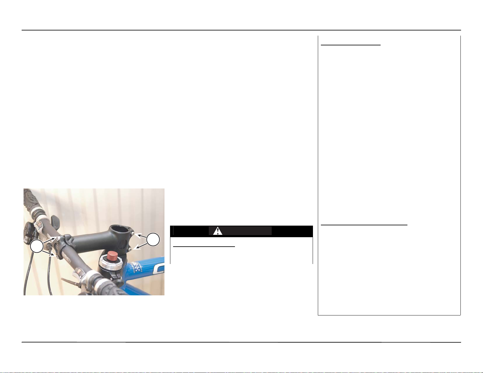
Stem bolts tightness
Make sure that the stem bolts that clamp the stem to
the fork are tight.
TORQUE : Stem bolts - 85.0 lbf•in (9.0 N•m).
1. Stem bolts
2. Handlebar cla mp bo lts
You can check that the stem bolts are tight enough
by standing in front of your bike, holding the front
wheel between your knees, and trying to twist the
handlebars fro m si de to side. The bars s houl d no t
move.
Front wheel attachment
Make sure the fron t whee l is attache d correc tly. Is
the Lefty hub correctly installed and the hub bolt
tightened to the specified torque? Refer to
"Installing the front wheel" starting on page 8.
Check the brakes
Are your brakes func tioning proper ly? With dis c
brakes, the brake pads must be properly installed
and free from grease or oil contamination. A lso,
brake pads must contact the braking surface firmly
with out the brake lever hitting the handlebar.
The Lefty fork must be used with a co mpati ble disc
brake system and it must be fitted correctly; the disc
brake mounted on a Lefty fork acts a secondary
wheel rete ntion device.
WARNING
POTENTIAL HAZARD
(1) Using the wrong disc brake system
(2) Incorrectly fitting/mounting brake discs
WHAT CAN HAPPEN
(1) The disc brake acts a secondary wheel
retention device. An improperly installed rotor
could allow the front wheel to come off of the
axle spindle if the hub axle bolt is loose. A rider
would be at risk of injury or death if the wheel
were to come off of the axle spindle while the
bike is being ridden.
(2) An approved disc brake system is very
important to safely riding the Lefty fork. Cannondale strongly recommend that an Authorized Dealer perform any work to the brakes.
When installing a disc brake to a Lefty fork,
please consult the disc brake fitting instructions that are included with the brakes. Those
instructions are provided for persons who
have a good knowledge of bike specific
mechanical procedures and who are equipped
with the proper tools and equipment. Incorrect
installation or se rvice may reduce br aking performance, and could lead to injury or death. If
you have any doubts about your ability to perform any necessary procedures, contact you
Authorized Dealer.
HOW TO AVOID THE HAZARD
(1) Don’t service the brake system yourself.
Always have your brakes serviced by an
Authorized Cannondale Dealer.
(2) Consult the manufacturer’s disc brake fitting instructions included with the brakes.
Those instructions are provided for persons
who have a good knowledge of bike specific
mechanical procedures and who are equipped
with the proper tools and equipment. If you
have any doubts about your ability to perform
any necessary procedures, contact your
Authorized Cannondale Dealer.
Note also that there is a seal that is held against the
disc side of the Lefty hub by the rotor. Whenever you
5
bolt the brake rotor onto the hub, be sure that the
N
seals rests against the large car tridge beari ng and
that the rotor holds the seal in place. The seal keeps
out water and dirt contamination, and a missing seal
will result in premature bearing wear.
brake line should pass from the lever through the two
cable guides on the outside of the fork leg.
6
5
OTE :
The brake line should not be held tightly in the
cable guides. The guide l oops need to be loos e
enough to allow the brake line to slide freely up
and down.
FORK SETUP
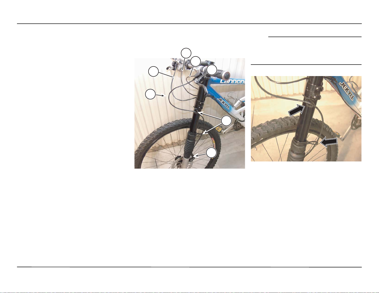
CABLE & LINE ROUTING
Front brake line
The front brake line routing shoul d not pass
between the headtube and fork leg. Rather, the
7
1
1. Fr ont br ake line
2. Fr ont brake line guides
3. Fr ont br ake cali per
4. Fr ont br ake leve r
5. Fr ont der a ill eur cabl e
6. Rear derailleur cable
7. Rear brake line
4
2
1
2
3
4
3
6
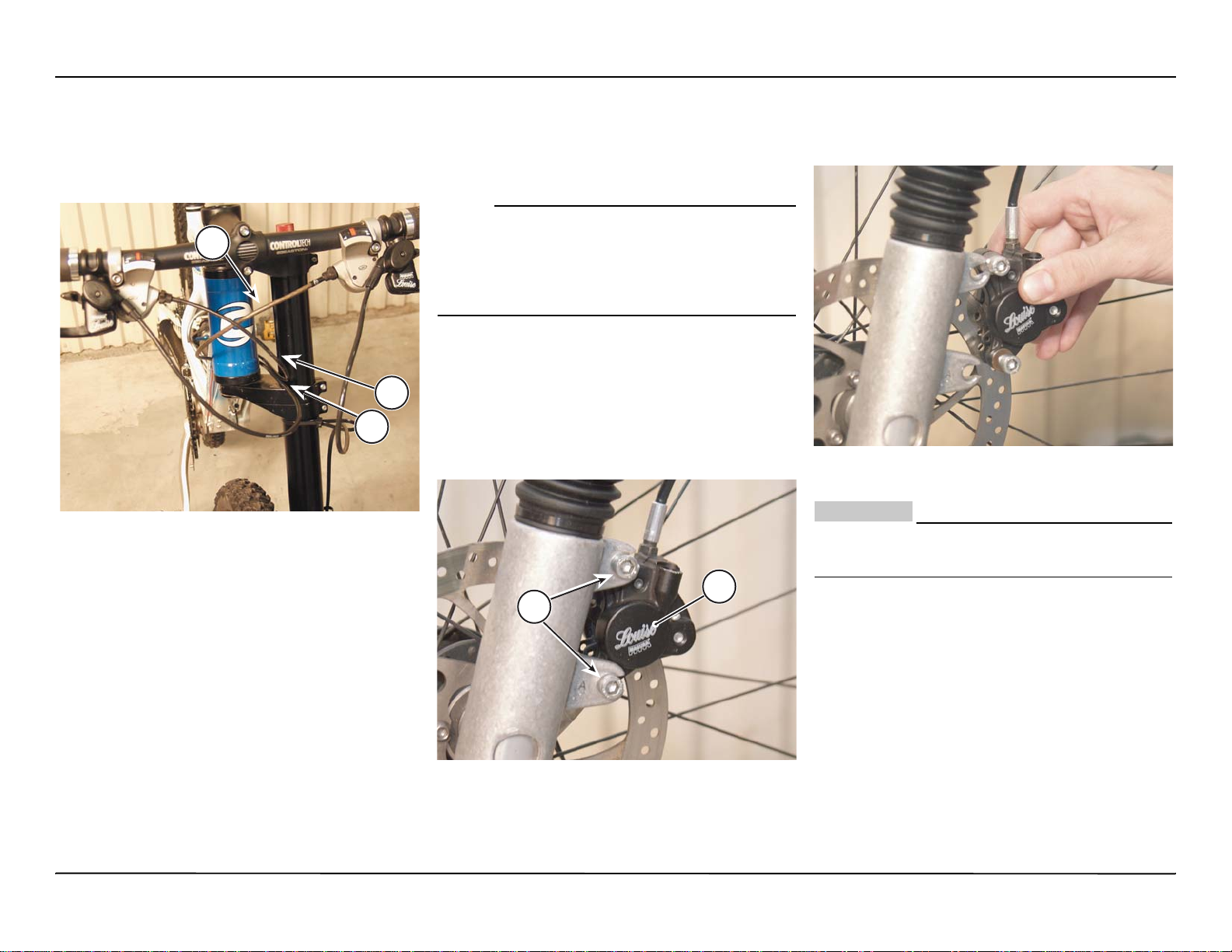
Rear brake line and rear derailleur cable
N
2
1
3
The rear brake line and rear derailleur cable shoul d
be run between the upper and lower fork clamps,
between the bikes headtube and fork leg.
bolt or beari ng be s ure to r eins tall the ca p with a
small amount of grease on the cap threads.
Remember that the cap is a left-hand thread.
OTE :
It is not necessary to remove the front wheel to
change an inner tube or tire. Simply remove th e
tire from the wheel as you normally would,
making sure to pull the tire off of the non-disc
side of the wheel.
Removing the front wheel
1. Secure the bike upright on a work stand.
2. Loosen (but don’t remove) both disc brake
caliper bolts (5 mm Allen).
from the brake disc (r otor). Take note of any
shims present and be sure to reinstall them
later during reassembly.
1. Rear dera ill eu r cab le
2. Rear brake lin e
3. Front de ra illue r ca ble
Don’t let the caliper hang. Support it carefully
out of the work area.
1
CAUTION :
2
FRONT WHEEL
4. Turn the axle bolt (5 mm Allen) counter-
The Lefty fork front hub uses a self-extracting bolt to
attach the wheel to the Lefty’s axle spindle. The bolt
is held into th e hu b by a cap that is screw ed in to th e
non-disc side of the hub using a pin spanner tool.
The self-extracting bolt and cap combination is very
similar to that used on a crankarm, except, a Lefty
hub cap is reverse threaded. The cap should not be
removed; it is there to hold the axle bolts into the
1. Br ake caliper
2. Bolts
hub. If you do need to remove the cap to replace the
3. Remove the caliper from the mount and away
7
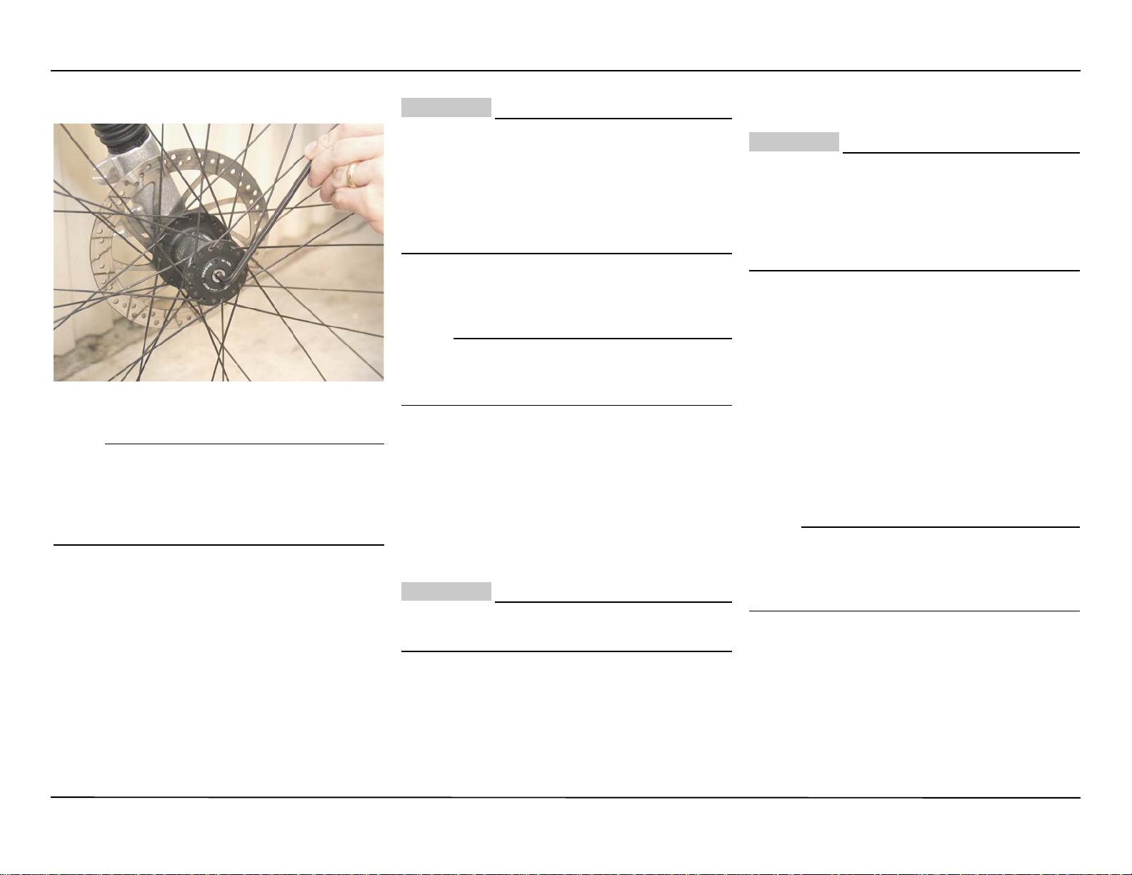
clockwise to loosen it.
NOTE :
N
N
CAUTION :
environments.
The bolt is held in the hub by the self-extracting
cap, and will stay attached to the hub even when
the wheel is removed from the axle spindle.
There is no need to remove that cap from the
hub.
5. Pull the wheel off of the axle spindle.
Take extra measures to protect the L efty axle
spindle from damage when the wheel is
removed. Dents, scratches, or other damage
from a fall or drop to the ground could
severely damage the s pi ndle preventing the
axle bolt from engaging the threads. The fork
could be ruined beyond repair.
Installing the front wheel
OTE :
Remove the front brake caliper from the Lefty
first. The front wheel can not be mounted with
the caliper installed.
1. Apply a light coat of high-quality bike grease to
the inside diameter of the larger cartridge
bearing located in the hub.
2. Apply a thin film of hi gh-quality bike grease to
the axle bolt threads inside the end of the
spindle.
CAUTION :
Take care not to contaminate the brake
caliper, pads, or disc with the grease.
3. Apply a light coat of high-quality bike grease to
the inner spindle axle bolt threads.
CAUTION :
Make sure the spindle (threads and the
spindle shaft) are completely clean before
applying any grease. A dirty spindle or dirt
trapped in grease applied can contribute to
excessive wear of the spindle greatly shorting
its service life.
4. Slide the front wheel onto the axle sp ind le wi th
the disc side of the hub closest to the fork leg.
Be sure to press the wheel straight onto the
spindle; so, the axle bolt th reads will co rrectly
engage with the threads in the spindle.
5. Tighten the front wheel axle bolt (5 mm Allen).
TORQUE : Front wheel axle bolt - 133.0 Lbf•in
(15.0 N•m).
OTE :
It is sometimes easiest to install the front wheel
by positioning the bike horizontally with the
spindle facing up. Then place the hub straight
down onto the spindle, and tighten the axle bolt.
6. Reinstall the brake caliper to the Lefty’s disc
brake mounts. You will first need to slip the
caliper over the brake rotor so that the rotor
runs between the brake pads.
Greasing the threads aids removal if the bolt is
over-tightened accidentally and can prevent
seizure in corrosive or punishing
7. Check to be sure that both brake pads are in
the caliper. Then slide the top caliper bolt into
the upper brake mount, and rota te the bottom
8
 Loading...