

Page 1

Electrical/EFI Service Manual
ATV and Motorcycle
P/N : 5002401
August 14, 2002
Page 2

8/14/02
INTRODUCTION
IMPORTANT NOTICE
You must possess si gni ficant mechanical knowledge, skills, and tool s to pe rfo rm mos t o f the
procedures found in this document.
This manual is written for Cannondale Motorsports Dealers and qualified service technicians.
This is not a comprehensive shop safety manual and should no t be used by anyone who is not
familiar with standard safety practices and service techniques. This manual does include
warnings and cautions (see descriptions above) that if ignored, could result in
SEVERE PERSO N AL IN JURY to the service technician or significant damage to the vehicle rendering it unsafe to operate. Anyone operating an “unsafe” vehicle can be SERIOUSLY INJURED
OR KILLED.
We have done our best to ide nti fy si tuat ion s w here warnings or cautions a re nee ded and wil l
continue to do s o i n f ut ure pu bl i c atio ns . Bu t, YOU must always exercise good judgement, and
follow safe shop practices when performing service procedures as described in this manual.
This manual was accurate at the time of publication. Any supplemental information developed
or written after printing may be available on our web site as a “manual supplement.” Service bulletins and technical notes are also published as required. These are also posted on the website.
You may find that the te chnical terms and part names in this manual differ from published parts
catalogs or microfiche.
ABOUT THE MANUAL
All the procedures in this manual are organized in a numbered (step-by-step) easy to read format with accompanying photographs, line art, torque values and specifications. The numbered steps of a few procedures are likely
to be separate pr o c ed ures th em s elv es . Wh en t hi s is th e c as e, t he nu m be re d ste p will include a page reference
number.
COMMENTS?
Send your comments to: Cannondale Corporation, Technical Publications, 2 Corporate Drive, Bedford, PA 15522
Or e-mail: technical.publications@cannondale.com
3
3
Page 3

© 2002 Cannondale Corporation - All Rights Reserved
IMPORTANT MANUAL INFORMATION
CAUTION:
NOTE:
FAILURE TO FOLLOW THE WARNINGS CONTAINED IN THIS MANUAL CAN RESULT IN SERIOUS INJURY
OR DEATH.
Information important to your safety is distinguished in this manual by the following notations: \
The safety alert symbol means......
“ATTENTION! BECOME ALERT! YOUR SAFETY IS
INVOLVED.”
DANGER
WARNING
Indicates that DEATH or severe injury WILL result
instructions are not followed.
Indicates a pote ntial ha zard tha t coul d result in serio us
injury or death.
A CAUTION indic ates that s pecia l pr eca ution s mu st be
taken to avoid damage to the machine.
A NOTE provides helpful information intended to make
maintenance easier or the instructions presented clearer.
if the
Electrical_EFI Service Manual.fm
4
Page 4

8/14/02
CONTENTS
INTRODUCTION - - - - - - - - - - - - - - - - - - - - - - 3
Important Notice - - - - - - - - - - - - - - - - - - 3
About the manual - - - - - - - - - - - - - - - - - 3
Comments? - - - - - - - - - - - - - - - - - - - - 3
IMPORTANT MANUAL INFORMATION- - - - - - - - - - - 4
ENGINE MANAGEMENT SYSTEM (EMS) - - - - - - - - - 6
Engine Control Unit (ECU) - - - - - - - - - - - - - 6
ECU Programming - - - - - - - - - - - - - - - - - 7
Servicing connectors and couplers - - - - - - - - - 9
Barometric pressure sensor - - - - - - - - - - - 10
Throttle position sensor (TPS) - - - - - - - - - - 10
Coolant temperature sensor - - - - - - - - - - - 12
Air temperature sensor - - - - - - - - - - - - - - 12
Crankshaft position sensor - - - - - - - - - - - - 13
Idle Air Control Valve (IACV) - - - - - - - - - - - 14
Ignition coil- - - - - - - - - - - - - - - - - - - - 15
EMS Power Relay - - - - - - - - - - - - - - - - 15
Fuel pump and fuel pressure regulator - - - - - - 17
Cooling Fan (ATV - - - - - - - - - - - - - - - - 20
CANNONDALE DIAGNOSTIC AND MAINTENANCE TOOL
VERSION 2.0 - - - - - - - - - - - - - - - - - - - - - - - 21
General Information - - - - - - - - - - - - - - - 21
Installation - - - - - - - - - - - - - - - - - - - - 21
In the Windows Explorer, double click the SecurityCode
application. Or, you can access this application by clicking
on Security code.exe through the program group. - - 22
Common Problems- - - - - - - - - - - - - - - - 23
Interpreting Error Messages - - - - - - - - - - - 24
Other Messages - - - - - - - - - - - - - - - - - 25
Communication cable - - - - - - - - - - - - - - 27
Cannondale Diag nos tic and M ai nte nan ce tool Main Window - - - - - - - - - - - - - - - - - - - - - - - - 28
ECU Operating code - - - - - - - - - - - - - - - 29
Calibrations - - - - - - - - - - - - - - - - - - - 37
ECU Monitor - - - - - - - - - - - - - - - - - - - 39
Reading Fault Codes- - - - - - - - - - - - - - - 40
Engine Stop Switch (ATV) - - - - - - - - - - - - 59
Clutch Lever Switch (ATV) - - - - - - - - - - - - 59
Key Switch - - - - - - - - - - - - - - - - - - - - 59
Starter Solenoid - - - - - - - - - - - - - - - - - 59
Starter Motor - - - - - - - - - - - - - - - - - - - 60
Fuses - - - - - - - - - - - - - - - - - - - - - - 60
FAULT TROUBLESHOOTING - - - - - - - - - - - - - - 42
Sensor Supply Voltage- - - - - - - - - - - - - - 42
System Voltage - - - - - - - - - - - - - - - - - 43
Fuel Pump - - - - - - - - - - - - - - - - - - - - 44
Ignition Coil - - - - - - - - - - - - - - - - - - - 45
Cooling Fan (ATV Only) - - - - - - - - - - - - - 46
Fuel Injectors - - - - - - - - - - - - - - - - - - 47
Throttle Position Sensor (TPS) - - - - - - - - - - 50
Air temperature Sensor- - - - - - - - - - - - - - 51
Coolant Sensor - - - - - - - - - - - - - - - - - 53
Idle Air Control Valve (IACV) - - - - - - - - - - - 55
Crankshaft Position Sensor- - - - - - - - - - - - 56
COMPONENT TESTING (NON-EFI)- - - - - - - - - - - - 57
Battery- - - - - - - - - - - - - - - - - - - - - - 57
Rectifier /Regulator- - - - - - - - - - - - - - - - 57
Flywheel - - - - - - - - - - - - - - - - - - - - - 58
Start Button (ATV & Motorcycle) - - - - - - - - - 58
Engine Stop Button- - - - - - - - - - - - - - - - 58
5
5
Page 5
© 2002 Cannondale Corporation - All Rights Reserved
ENGINE MANAGEMENT SYSTEM
NOTE :
(EMS)
Engine operation is supported by the management
system consisting of three main types of electrical
components: the ECU, the sensors, and the actuators.
Motorcycle ECUs are located within the subframe.
3
1
• The engine control unit (ECU or ECM) precisely
calculates ignition timing and fuel delivery for al l
engine speeds and loads (based on the
currently installed calibration file and its
mapping). The ECU is an extremely reliable
component and should be the last component
checked in the event there is a problem with the
fuel injection system.
• The sensors of the system collect engine
operating information and transmit it to the
ECU.
• The actuators are devices like the fuel injec tors,
fuel pump, fuel pressure regulator, and spark
plug coil, and relays.
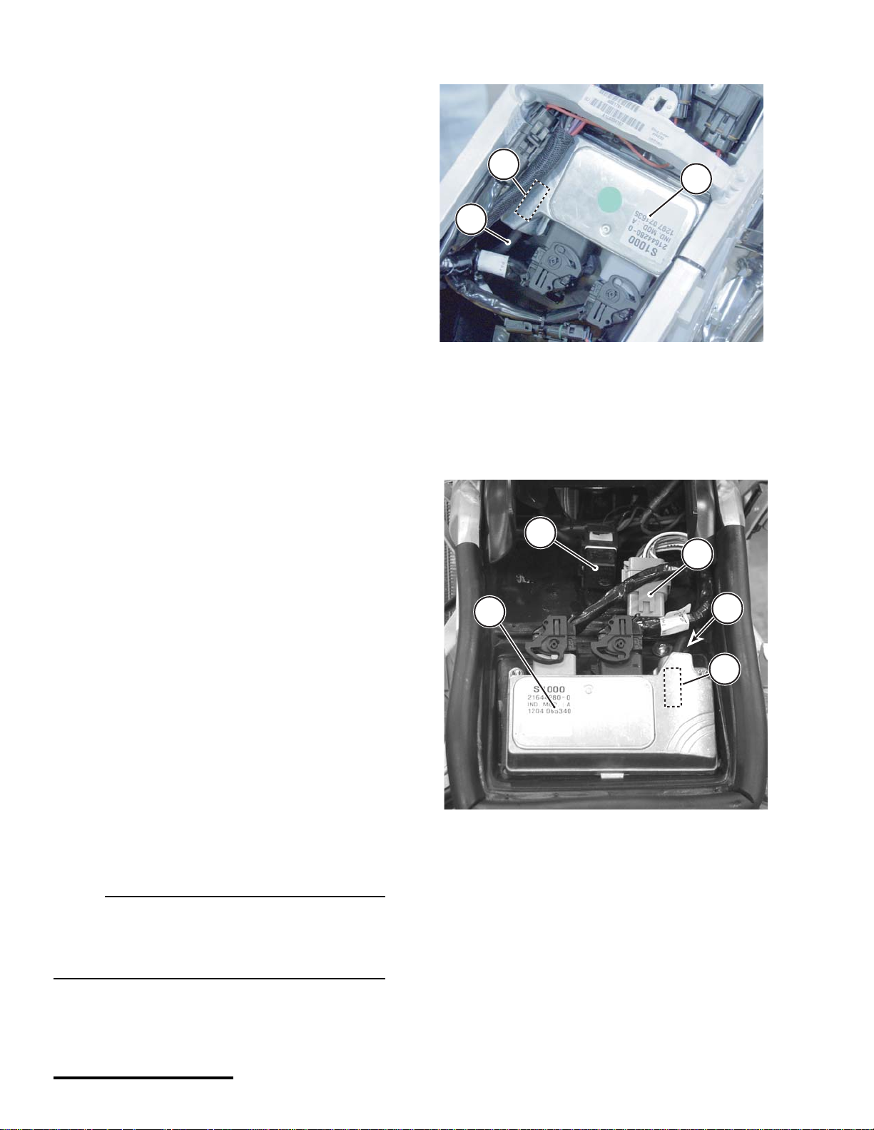
ENGINE CONTROL UNIT (ECU)
The engine control unit or “ECU” is a kind of computer that calculates ignition timing and fuel delivery
for all engine speeds and loads based on its programming. It is s om eti me s r efe r red to as th e “br ai n”
of the fuel injection syste m . Thi s brai n ca lc u la tes fuel
delivery and ignition timing based on information
gathered from ve hi c le sensors (inputs) a nd th e ca l ibration file loaded at the factory.
2
1. ECU
2. Air pressure sensor hose (from airbox and fuel pressure
regulator)
3. Internal barometric (air) pressure sensor.
A TV ECUs are located on the electronics tray under
the cowl.
4
3
1
2
3
The ECU inputs are the air temperature, coolan t,
crankshaft position, throttle position, and barometric
pressure sensors. Information from these sensors
together with the ECU operat ing code ( hex file) an d
engine calibration file (map) are used to control the
system actuators (e.g. fuel pump, ignition coil,
injectors, relays, idle air con trol valve).
In this manual, the engine control unit is referred
to as the “ECU.” It is also sometimes called an
“ECM” or engine control module. Ei ther reference
is OK.
Electrical_EFI Service Manual.fm
1. ECU
2. Air pressure sensor hose (from airbox)
3. Accessories connector
4. EMS power relay
6
Page 6
8/14/02
ECU PROGRAMMING
The ECU is “programmed” with three types of information. the operating code (also known as the “hex”
file, the engine calibr ation file (also kn own as t he
“map”), and the vehicle variables or “calibrations.”
Calibrations are stored in the map file but are specific
to the throttle body and injectors installed on the
vehicle.
of the ATV.
The tool is a combination of a specially developed
Windows- based software program and a data cable
used to connect your PC or pocket PC computer to
your vehicle. With the tool, you can read fault codes,
install engine calibration fil es, set v ehicle rpm , and
monitor engine operating parameters.
Any programmed information can be changed.
using the Cannondale Diagnostic and Maintenance
Tool. Refer to "Cannon dale Diagnostic a nd Maintenance Tool Version 2.0" starting on page 21.
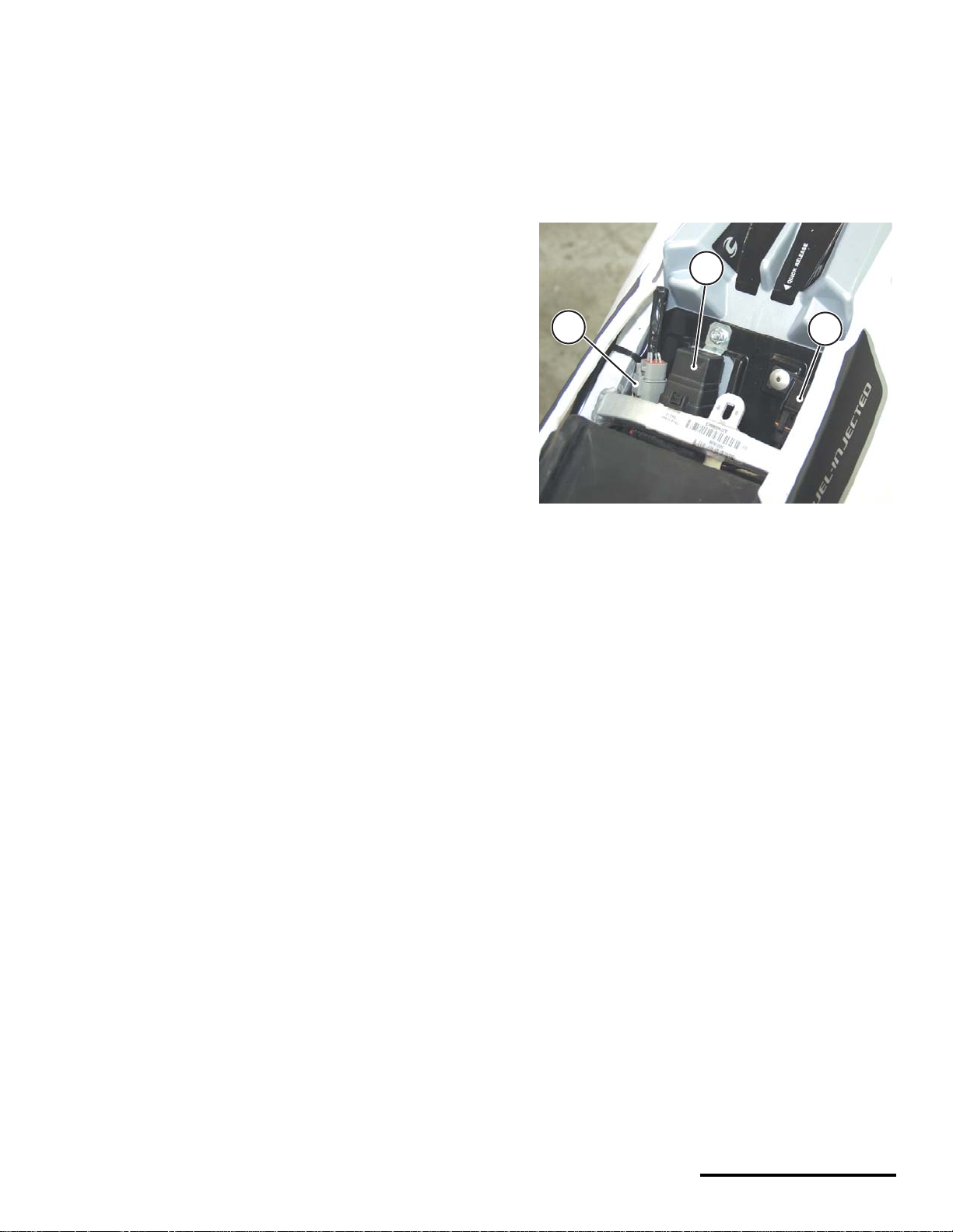
ECU diagnostic connectors
ATVs and motorcycles have a diagnos tic connector to connect the software tool PC to the vehicle.
• On 2001 and 2002 Motorcycles, the diagnostic
connector is located near the ignition coil on the
top of the cylinder head.
• On 2003 motorcycles, the diagnos tic connector
is located near the main fuse under the seat.
• On 2001 - 2003 ATV the diagnostic connector is
located near the radiator shroud on the left side
2
1
1. Diagnostic connector
2. EMS power relay
3. Main fuse
3
Reporting system faults
The ECU is capable of reporting system hardware
malfunctions during operation. It reports current
problems and does not store problem “faults” in
memory.
System faults are read from the ECU using the
Cannondale Diagnostic and Maintenance Tool, a
Windows-based PC pro gram enabling c ommunication between a PC and the vehicle ECU. The ECU
does not store intermittent fau lts; the fa ults repor ted
are occurring at the mom ent when the ECU Fault
Report windo w is s elect ed i n th e s oftwa re to ol. A
special commu nicati on ca ble is neede d to co nnect
the vehicle to a PC. Refer to "Cannondale Diagnostic and Maintenance Tool Version 2.0" starting on
page 21.
This manual provides step-by-step fault diagnostic
testing based on the ac tual fault repor ted by the
software tool. Refer to "Fault Troubleshooting"
starting on page 42.
7
7
Page 7
© 2002 Cannondale Corporation - All Rights Reserved
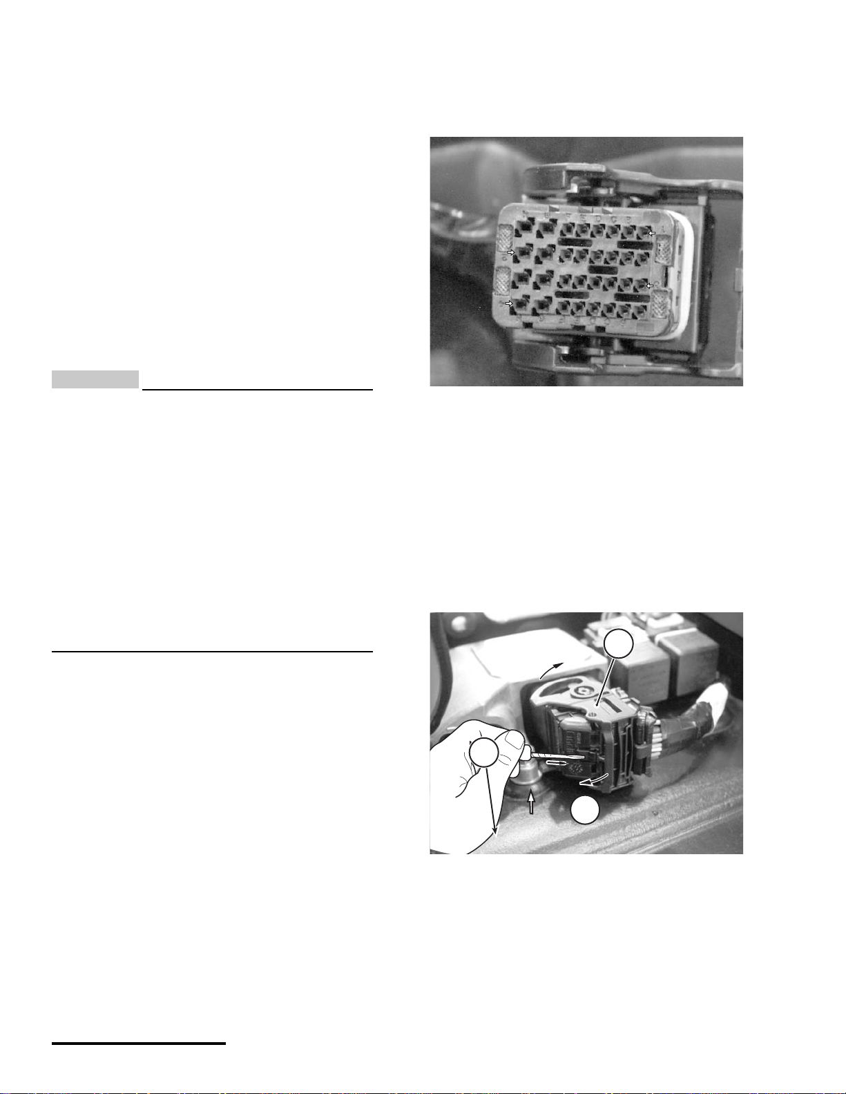
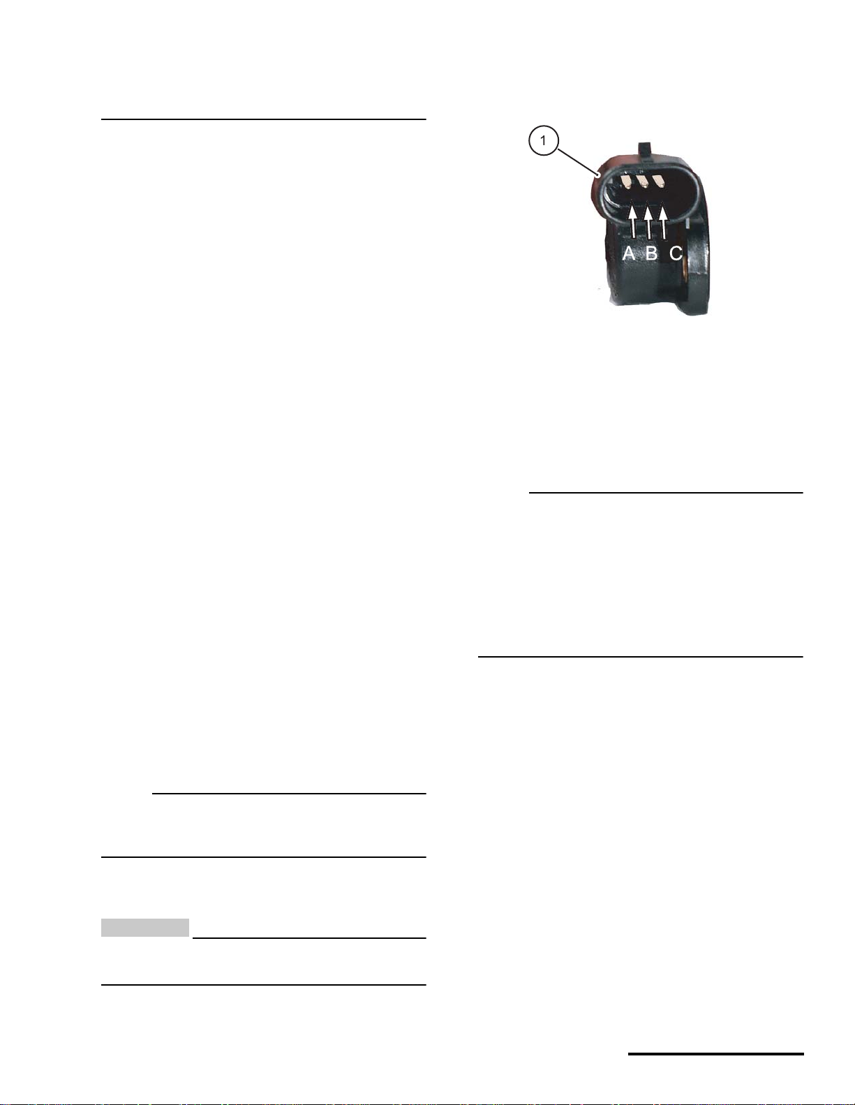
P1 and P2 Connectors
H
Pin identification (P1 or P2)
MC1000 ECUs have two main harness connector
sockets.
Remove both main harness connectors from the
ECU when performing pin point tests described in
this manual.
Also, if requir ed, be su re t o d iscon nect any oth er
devices; see the specific pin point tests.
• Connector P1 color is bl ack. It connects to the
black ECU socket.
• Connector P2 color is grey. It connects to the
grey ECU socket.
CAUTION:
Allow connector rotating latch to draw the
connector into the ECU socket (coupler) . Do not
press or force the connector; it should slide
into the socket easily.
Check for contamination and pin condition
before reconnecting.
Lubricate the connector seals with a highquality dielectric grease before reinstalling.
Use a commercially available pin gauge when
performing pin point tests. Ordinary tester
probes can spread pins resulting in loose
connections.
Use the following illustration for P1 and P2 pin iden-
tification.
H
G
F
E
D
C
B
A
1
2
3
4
H
G
F
E
D
C
B
A
This photo shows how to identify individual pins in the ECU
harness connectors. Each row is identified by a number 1-4.
Each column is identified by a letter A - H.
Disconnecting the ECU
1. Disconnect the battery.
2. Press in the latch lo cking tab and rotate the latch
in direction (a) until it stops. Pull the connector
from the ECU socket.
1
Electrical_EFI Service Manual.fm
1
a
1. Latch
2. Locking tab
Reconnecting the ECU
1. Make sure the battery is disconnected.
2. Make sure the main fuse is removed.
8
Page 8
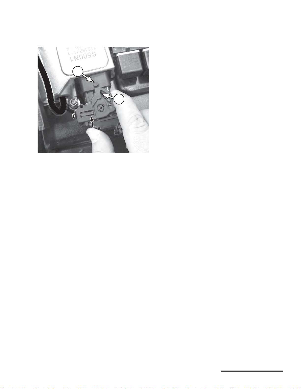
8/14/02
3. Align the latch groove and tab on the ECU socket.
Rotate the latch in direction (b) until the latch is
locked by the locking tab. The latch should operate freely with your fingers; do not force it.
2
Cleaning
1. Wipe the connector or coup ler with a clean, lintfree rag and blow off any moisture using
compressed air.
2. Remove corrosion, rust, stains or other foreign
material by using contact cleaner on the terminals.
3. Apply a water-displ acement chemi cal on connec tor seals.
1
1. Latch
2. Tab
SERVICING CONNECTORS AND COUPLERS
Many electrical problems could be caused by faulty
electrical connectors or couplers. Check for the following conditions before beginning any diagnostics:
• wet terminals/pins
• dirty or corroded terminals/pins
4. Apply a light coat of dielectric grease onto the terminals/pins, and properly connect the halves.
Disconnecting
• Release any locking device fir st.
• Do not pull the leads.
Connecting
• Inspect for bent terminals/pins, damaged c able
terminal/pin joints, water, dirt, or corrosion, and
secure wiring. If a terminal or pin is bent,
carefully straighten it with a thin-blade
screwdriver.
• Before joining or connecting, check for dirt or
corrosion
• Push male and female ends together squarely
to avoid incorrectly locating or bending the
terminal pins.
• broken bent cable pins within multi-plug
couplers
• terminal pins backing out of the connector or
coupler
Connector - a single male lead that connects into a
single female lead.
Coupler - multi-pins and usually have some sort of
locking device (e.g., barb, hook, eye) which must be
released before the two halves can be separated.
• Whenever a connector or coupler is
disconnected or checked, be sure to clean it
and apply some dielectric grease before
reconnecting.
• Make sure the two halves connect positi vely.
9
9
Page 9
© 2002 Cannondale Corporation - All Rights Reserved
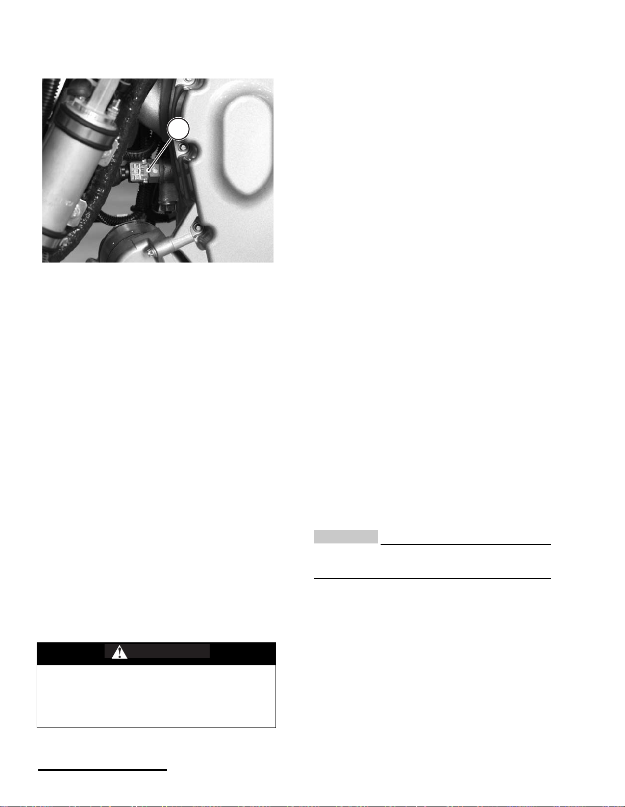
BAROMETRIC PRESSURE SENSOR
NOTE :
NOTE :
N
The barometric pressur e sensor is housed within
the ECU. Air pressure within the airbox is transferred
to the ECU by a narrow hose. Air pressure information is used to adjust the amount of injected fuel to
match the prevailing conditions. The sensor is not
user serviceable. If no external problems are found
with the hose or the hose routing end points, and a
barometric pressure sensor fault persists, the ECU
will have to be replaced.
When performing tests, start by checking the hose
routing from the ECU to the airbox. The routing
may be interconnected with other devices. Be sure
to check all vacuum/pressure routing hoses for
damage.
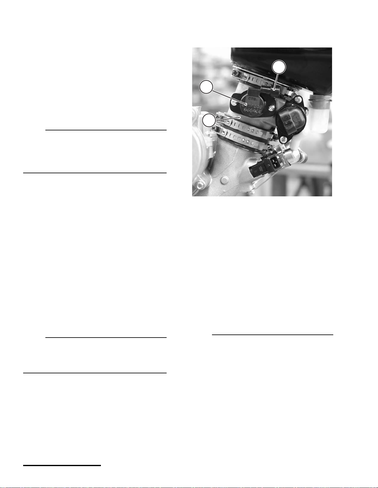
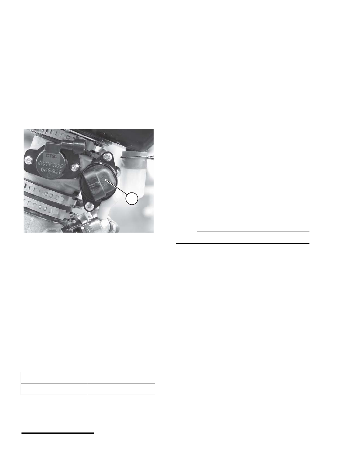
THROTTLE POSITION SENSOR (TPS)
3
1
2
Dynamic Test - ECU Monitor
1. To test, determine the barometric pressure at
elevation in the operating area.
2. Read the reported sens or data with the Cannon-
dale Diagnostic and Maintenance Tool. This value
is reported at the “ Airbox Pressure (k Pa)” field in
the ECU Monitor window. Refer to "ECU Monitor"
starting on page 39.
3. Compare the known value with the one repor ted
by the software tool. If the comparison of the
actual value and the reported value results in a
wide dis pa ri t y, and no ot he r fa u lt s ar e present and
engine trouble remains, consider replacing the
ECU.
When comparing the actual barometric pressure
reading and the one reported through the
software, be sure to convert to equivalent units
(kPa).
1. TPS Sensor
2. Throttle Body
3. Harness connection point
The throttle position sensor (TPS) is a rotary potentiometer attached to the end of the throttle plate shaft
on the right side of the throttle body.
Fueling requirements are calculated by the ECU for
changing throttle positions.
The fully closed and fully open thr ottle positions
(interpreted by the minimum and maximum voltage
read through the sensor) are stored as numeric
values in the ECU.
OTE :
Anytime the throttle body is servic ed or the sensor
is removed or replaced, the min/ma x values must
be re-read into the ECU using the Update
Calibrations window of the tool.
Electrical_EFI Service Manual.fm
Use the Cannondale Diagnostic and Maintenance
Tool.
Refer to "“Throttle Body Leakage” (also called
Throttle Body Offset) (Input range 0 - 100) The
equivalent amount, in percent, of throttle openi ng
10
Page 10
8/14/02
required on a “perfect” throttle body to match the
N
N
air flow of the vehicle's throttle body at the closed
position. Typical values are from 0.0 to 1.0%"
starting on page 37.
The TPS sensor signal informs the ECU of not only
the relative position of the throttle plate, but also the
speed with which it is being opened or clos ed. The
engine load is determined by the TPS and engine
speed (rpm). The voltage output from the TP S
increases proportionately as the throttle is opened.
The sensor contains no user serviceable items.
Dynamic Test - ECU Monitor
1. Use the ECU Monitor windows of the Cannondale
Diagnostic and Maintenance Tool and read the
Throttle position (%) fi eld . T his field is the percent
the throttle plate is open as translated by the
ECU. With the throttle plate completely closed,
this value shoul d read between 2% to 3 %. When
the throttle is fully opened, a normal reading is
97% to 100%. When the idle adjustment is set,
this value should be approximately 3% higher
than the completely closed percent to achieve
rough idle. Fine tuning of the idle adjustment
screw which changes the% percent may be
required
If the Throttle Position (%) field values in the ECU
monitor window are erratic or inconsistent as
described above, the sensor can be tested further
by removing it and reading the resi stance values
with an Ohmmeter.
Static Test - Resistance
1. TPS sensor (shown removed)
1. To test the sensor resistance, remove the sensor
harness connector, remove the mounting bolts,
and remove the sensor from the throttle body.
OTE :
Removing the sensor from the throttle pla te shaft
to measure the resistance is not required.
Removing it and inspecting the housing and shaft
socket for damage can be helpful. Remember that
is the sensor is removed, you will have to reset the
sensor min and max values using the software
tool. Refer to "Setting the throttle position sensor
minimum and maximum values" starting on
page 34.
2. Attach a vacuum pump/pressure pump to the
hose end and monitor change. The reading
should increase when increased pressure is
applied. The reading should decrease when vac uum is applied.
OTE :
Be sure to convert the atmospheric pressure units
displayed in the ECU monitor window with units
displayed with the tools.
CAUTION:
Use of high pressure or vacuum when testing
may damage the sensor diaphragm.
11
11
2. Measure resistance across sensor terminals A
and B.
The resistance should be 1200 ± 240 Ohms.
3. Measure the resistance across sensor terminals
A and C.
- slowly rotate the sensor wheel clockwise and
observe variable resistance. Resistance should
increase smoothly from 0 to 1200 ± 240 Ohms.
Page 11
© 2002 Cannondale Corporation - All Rights Reserved
COOLANT TEMPERATURE SENSOR
G
1
1. Coolant temperature sensor (ATV shown)
The coolant temperature sensor is brown in color
and located on the front of the engine cylinder head.
It is an NTC thermistor.
3. Compare the values . If the two va lues do not cor respond closely, the sensor may be damaged. Go
to the next step.
4. Be sure to repl ace the radiator cap a nd start the
engine and allo w to reach operating temperature
(60°C). Observe the Engine Temperature (degC)
field in the ECU Monitor window. If the value does
not increase as the eng ine warms, go to the next
test.
Static Test - Resistance
1. Disconnect the sensor harness connector.
2. Use an Ohmmeter to measure the sensor resistance between terminal s 1 an d 2 . Refe r to " Coo lant Sensor Resistance Range" starting on
page 54. If measured resistance is inconsistent at
the tested temperature r eplace the sensor. If the
sensor is OK, the sensor harness wiring or the
ECU itself may be damaged. Take corrective
action.
The ECU measures the current flow through this
thermistor to groun d and u ses it to det ermin e the
engine coolant temperat ure. The ECU calculates
fueling to optimize engine performance at all tempe ratures. It also calculates hot and cold start fueling
requirements.
The sensor resistance decreases as the temperature increases.
Dynamic Test - ECU Monitor
1. Starting with a completely cool engine, use the
ECU Monitor window of the Cannondale
Diagnostic and Maintenance Tool to read the
Engine Temperature (degC) field in the ECU
Monitor window. Refer to "Using the ECU
Monitor" starting on page 39.
2. Open the radiator cap and tes t the coolant tem-
perature with a thermometer.
WARNIN
Never open the coolant system when the
engine is hot. Coolant is hot and under
high pressure. It can spray out forcefully
and burn or scald you severely.
AIR TEMPERATURE SENSOR
The intake air temperature sensor is attached to the
airbox with the tip mounted inside the airbox.
It is a NTC thermistor and green in color.
Resistance will drop as temperature rises.
The sensor tip is very sens itive to temp erature
change.
CAUTION:
The tip can be damaged easily; use extr a care
when installing or working inside the airbox.
The ECU uses the information from this sensor to
calculate the fuel necessary for a given air temperature.
Dynamic Test - ECU Monitor
1. Use the ECU Monitor window of the Cannon dale
Diagnostic and Maintenance Tool to read the
Engine Temperature (degC) field in the ECU
Monitor window. Refer to "Using the ECU
Monitor" starting on page 39.
Electrical_EFI Service Manual.fm
12
Page 12

8/14/02
2. Compare the value with a reading taken manually
N
in the vicinity of the ai r temperature tip. If the two
values do not corre sp ond clos el y, the sensor may
be damaged.
Static Test - Resistance
1. Remove the sensor from the ai rbox by pl acing an
open-end wrench o n the sen sor body and turni ng
it counter-clockwise until it can be removed.
This senso r de te cts mo ve me nt of a toothed whee l
that is molded into the flywheel and attached to the
right side of the crankshaft. The wheel has a 36-tooth
pattern. The flywheel teet h are ev enly s paced wi th
the exception of one, tri ple -leng th to oth next to one,
triple-length gap. Everytime this tooth/gap passes the
sensor, the ECU interprets i t as b ott om de ad c en te r
(BDC). The EC U u s es t hi s i nf orm ati o n t o de ter m i ne
engine speed and crankshaft p osition i n relation to
the point where fuel is injected and ignition of the air/
fuel mixture occurs.
2. Measure the sensor resistance between terminals
1 and 2. Refer to "Air Temperature Sensor Resistance Range" starting on page 52.
If the measured res istance is inconsistent at the
tested temperature, replace the senso r.
If the measured resistance closely matches the
table values, the sensor is OK, the sensor harness wiring or the ECU it self may be damaged.
Take corrective action.
CRANKSHAFT POSITION SENSOR
1
If the crankshaft position sensor malfunctions, the
engine will not start. If the sensor tip is contaminated
with metallic debris, oils and dirt, or incorrectly
gapped, the engine can run erratically.
If the flywheel is damaged, the sensor may be ok,
but may be reading bad information due to the
resulting change in the ind e xing betwe en th e c ra nkshaft and flywheel teeth. Refer to "Flywheel" starting
on page 58.
OTE :
Metallic debris or other contaminants on the
sensor tip will affect the sensor.
Inspection points
1. Ensure sensor connection to harness is secure.
2. Check sensor gap: 0.5mm-1. 0mm .
a
2
The flywheel cover has been removed for this photo to show the
sensor tip.
1. Crankshaft position sensor
2. Sensor tip
3. Flywheel tooth
4. Gap
SERVICE: Crankshaft position sensor gap
0.02 - 0.03 in (0.5 -1.0 mm)
The crankshaft position sensor is located in the
generator housing.
3. Check for magnetic debris on sensor tip.
4. Check for damaged flywheel teeth.
5. Check flywheel for run-out or play.
6. Check flywheel hub for cracking o r separati on.
Dynamic Test - ECU Monitor
1. Use the ECU monit or window to confirm change
in reported engine rpm.
With the engine off, there should be no reading
displayed at engine rpm field.
Crank the engine over and a reading should be
displayed. If no change is observed, the sensor or
harness circuit is faulty. Take corrective action.
13
13
Page 13
© 2002 Cannondale Corporation - All Rights Reserved
Static Test - Resistance
N
1
1. Disconnect the sensor harness connector.
2. Use an Ohmmeter to mea sure the sensor resistance between terminals 1 and 2.
SERVICE: Crankshaft position sensor
resistance range - 532 TO 588
Ohms
In a cold engi ne, th e val ve ope ns (ar m retr acts)
allowing more air to bypass the throttle plate. As the
engine warms up, th e valv e closes (a rm extend s)
until the bypass channel through the housing is completely shut at 60°C.
Here are some symptoms of a faulty IACV
• Hard starting - the valve arm could be stuck
shut. In this case, the extra air needed for cold
starting conditions is not available. Enough air
may be available to start a warm.
IDLE AIR CONTROL VALVE (IACV)
1. Idle Air Control Valve (IACV)
The Idle Air Control Valve (IACV) is an ECU c on-
trolled valve mounted on the throttle body.
As soon as the ECU is powered up, this valve
begins to move to the correct position (increasing or
decreasing the available air bypass volume needed
for cold start). The ECU co ntrols the valve arm
depending on engine temperature. The valve arm
moves in “steps” that extend or retract the valve arm
inside the bypass housing.
• Engine idles too fast - valve is s tuck open.
• Rough idle - if the valve arm is malfunctio ning
Dynamic Test 1 - ECU Monitor
1. Make sure the engine is completely cool.
2. Use the Cannondale Diagnostic and Maintenance
Tool to read current valve stepped position with
the cool engine.
Read the valve posi tion at IACV Stepper Positio n
field in the ECU Monit or wind ow. Refer to "Usin g
the ECU Monitor" starting on page 39.
OTE :
Make sure the monitor is in “continuous” m ode.
3. Start the engine and allow to it idle normally.
Observe the IACV Stepper Position and Engine
Temperature ( degC ) fie ld s. As the engi ne temperature climbs, the IACV Stepper Position should
increase indi cating that the arm is extending and
the bypass channel in side the housing reducing.
At engine operatin g temperature (60°C) the arm
should be fully extended and the bypass closed.
4. If no change is observed, go to Dynamic Test 2.
The arm travels.024mm per step.
Total travel = 0 to 255 steps
IACV Stepped positions
Fully Open Fully Closed (at 60°C)
175 205
Electrical_EFI Service Manual.fm
Dynamic Test 2 - Confirm arm movement
1. Make sure the vehicle engine is compl etely cool
and press the engine stop button to ensure that
the ECU is powered down.
2. Remove the bypass housing from the throttle
body with the IACV valve attached to it.
14
Page 14

8/14/02
CAUTION:
G
3. Check the co ndi tio n of the tip in sul ator. Make sure
it is not cracked, burned, melted, dried out.
Do not remove the valve from the housing whe n
performing this test.
3. Disconnect the engine coolant sensor.
4. Reconnect the idle air control valve to the harness.
5. Press the engine s tart button quickly without tu rn ing over the engine. The valve should extend fully.
6. Reconnect the coolant sensor and observe movement of the valve arm; the valve should retract
slightly.
If the valve does not mov e, replace it with a new
one.
Static Test - Resistance
1. Remove the valve moun ting screws and remove
the valve from the bypass housing.
2. Inspect the housing pintel seat and valve pintel
end for damage.
4. Make sure the spring is installed with the larger
end facing the coil.
Dynamic Test - Spark Occurrence
WARNIN
An energized ignition coil generates a
high voltage spark capable o f jumping to a
ground point. The following procedure will
create a spark that can ignite any available
fuels. You can be seriously injured or killed
in a resulting fire or explosion.
Make sure the work area and vehicle are
free of any gasoline or flammable liquids
(flooded engine, fuel tank, fuel hoses, solvents).
1. Disconnect the ignition coil from the harness
connector.
2. Remove the retaining clip bolt and coil retainer.
3. Lift the ignition coil out of the cylinder head.
3. Measure resistance across sensor terminals (A)
to (D). The resistance shoul d be 53
4. Measure resistance across sensor terminals (C)
to (B). The resistance should be 53
± 10% Ohms.
± 10% Ohms.
IGNITION COIL
The ignition coil is a “pencil-type” coil located on top
of the spa rk plug within the cylinder head.
The ECU controls when the coil is switched on or
off. The coil is switched on to allow sufficient time for
the coil to charge to a level w here a spark can be
produced at the spark plug. The coil switches off at
ignition, which is timed for good engine performance.
Inspection Points
1. Check the coil body for damage (e.g., burning,
cracks, discoloration (excessive heat).
2. Check the coil termin al pins. Make sure they are
in good condition.
4. Reconnect the harness.
5. Insert a commercially available spark tester into
the end of the coil. Connect the ground lead of the
indicator to the cylinder head.
6. Turn the ignition switch o n and press the engine
start button. If spark is indicated, the coil is OK.
Static Test - Primary Resistance
1. Measure the res istance between t he coil termin al
pins.
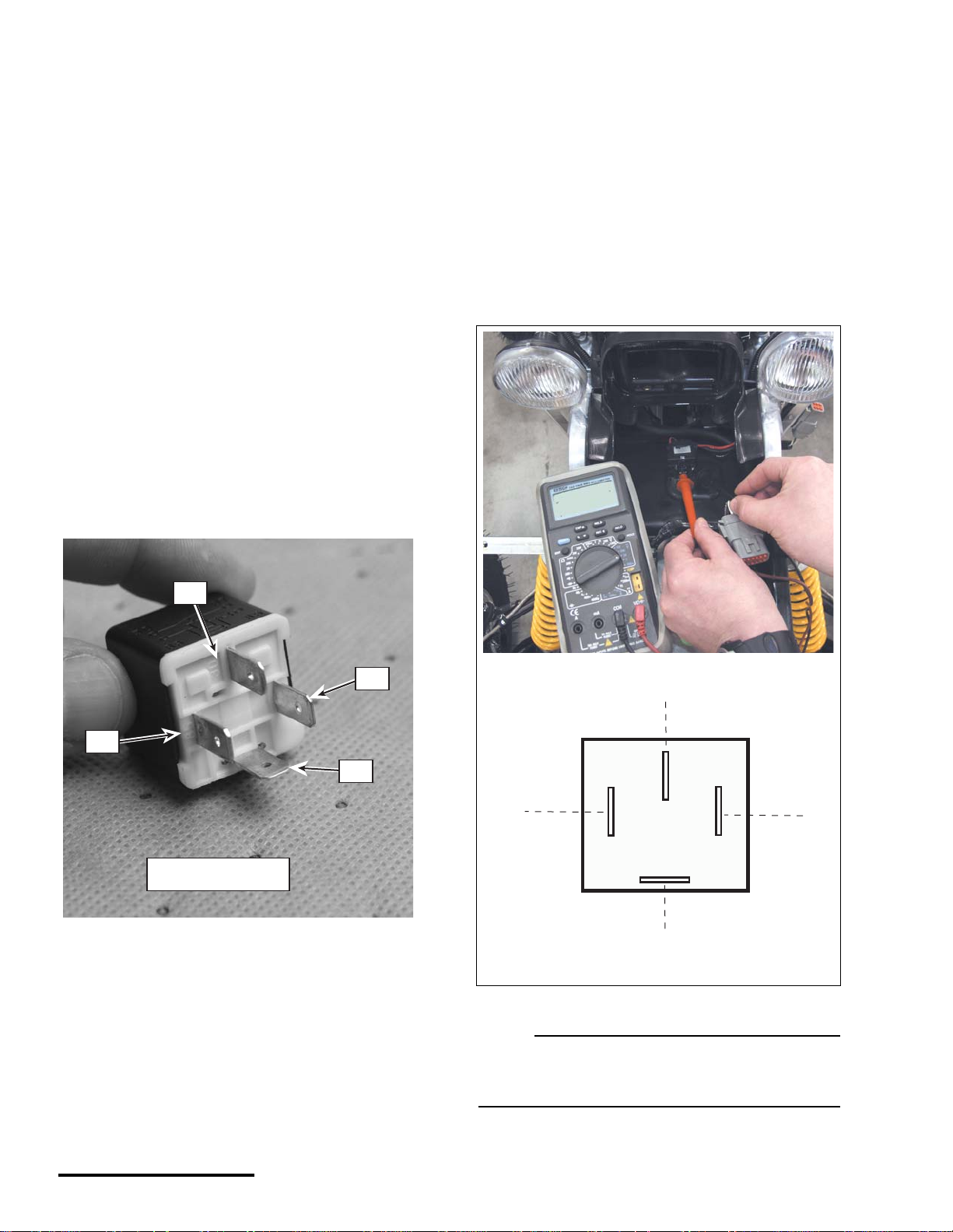
EMS POWER RELAY
The EMS power relay supplies the ECU with power
when the vehicle start button is pr essed and will
remain locked when the engine is runn ing. The
relay will hold for up to 2 minutes without the engine
running or turning over, then it will drop power to
ECU.
15
15
Page 15
© 2002 Cannondale Corporation - All Rights Reserved
On motorcycles, if this relay is damaged, the
N
"30"
"85"
"87"
"86"
RELAY - P/N 5000411
engine can start but will shut down when the start
button is released.
number 85. There should be continuity
between terminals 30 and 87. If the re is not,
the relay is damaged; replace it.
On ATVs, if this relay is dam ag e d or r e mo ve d, th e
engine will run, but damage to a harness diode will
result. When the diode fails, the engine will not run.
Dynamic Test
1. Remove the relay from its harness socket.
2. Using an ohmmeter, connect the positive probe
(+) onto terminal number 86 and the negative
(-) probe onto terminal number 85. Check the
resistance. The resistance should be 1500
± 10%
Ohms.
Reverse the meter le ads. If th e readin g is OL (n o
continuity), go to the next step.
If the relay is out of specification, replace the relay
with a new one. If the measured resistance is OK,
go to the next step.
5. Use a voltmeter to verify tha t there is vo ltage
present at the wiring harness socket
corresponding to relay terminal 87. Do not
start the engine. If there is no voltage present,
check the main fuse. Use the vehicle wiring
diagram to check the c ircuit. Take correctiv e
action.
There are no markings on the socket itself;
use the illustration below for identification.
12.5 VDC
3. Using an Ohmmeter, connect the positive
probe (+) onto terminal number 30 and the
negative (-) probe onto terminal number 87.
Check the for continuity. There should be no
continuity. If continuity is observed, the relay
is damaged; replace it. If no continuity is
observed, go to the next step.
4. Connect 12 V (+) battery voltage to the
number 86 terminal and ground terminal
30
85
86
SOCKET
87
OTE :
Wiring diagrams are available on our web site.
http://www.cannondale.com/motorsports/tech/
servman.html
Electrical_EFI Service Manual.fm
16
Page 16
8/14/02
N
OTE :
N
N
N
When the ignition switch is turned “ON,” the
installed relay will make an audible “ clic k.”
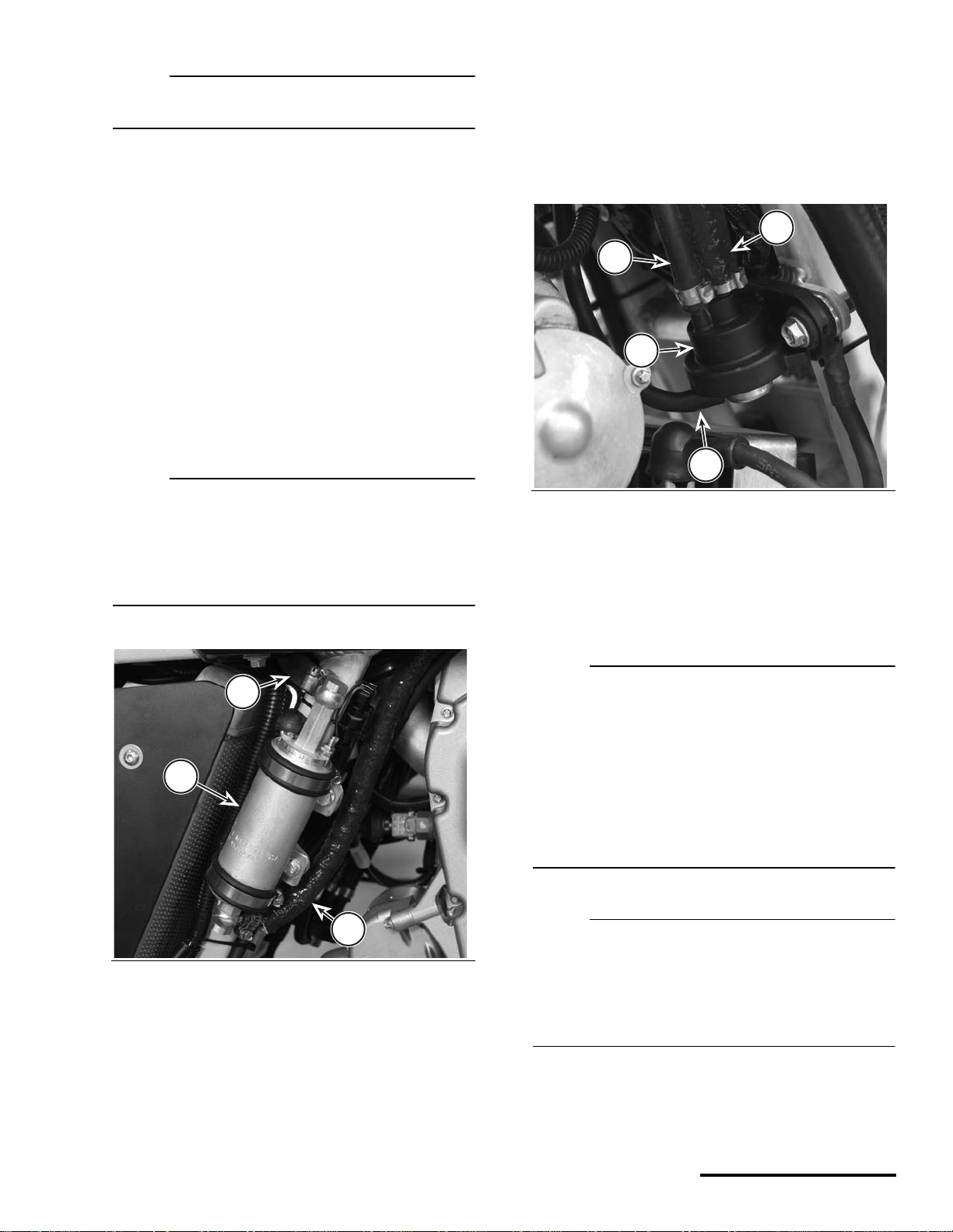
FUEL PUMP AND FUEL PRESSURE REGULATOR
The fuel pump and regulator maintain fuel supply
and pressure to the injectors. When the engine management system is first “powered-up,” this pump activates for 3 seconds to pressure the fuel system then
turns off again until the engine starts. When the
engine starts, it resumes pumping, providing pressurized fuel to the injectors. The regulator returns
fuel to the fuel tank.
The fuel pressure regulator maintains the correct
fuel pressure in the fu el rai l ( ho ses an d i nj ect or s ). It
returns fuel to the tank after fuel passes the fuel
injectors. The regulator is connected to the airbox via
a small hose. On ATVs the fuel pressure regulator is
mounted on the main frame on the right side of the
vehicle (front).
3
2
1
OTE :
The positive (+) pump terminal is always “hot” even with the ignition switch OFF. Thi s terminal is
connected directly to the positive battery voltage
through the main fuse. The pump is acti vated by
ECU switching the negative circuit to ground.
Consult the vehicle wiring diagram for more detail.
3
1
2
1. Fuel pump
2. Fuel inlet (from tank)
3. Fuel outlet (to injectors)
4
Components have been removed for this photo.
1. Fuel pressure regulator housing
2. Fuel hose (from injectors)
3. Fuel hose (return to tank)
4. Air pressure hose (from airbox)
Dynamic Test - Pump and Regulator
OTE :
If you suspect a problem with the fuel pump, first
check to see if it runs at all. Do the following :
Turn the ignition switch “ON” and listen to the
pump, it should make a “whirring” sound for a few
seconds to pressurize the syste m - then the pump
will turn off.
Start the engine and allow the vehicl e to idle. You
should hear a constant whirring” sound - although
it is more difficult to hear.
OTE :
The pump will turn anytime the start button is
pressed on motorcycles, however, the pump
circuit is different is different on ATVs. If the ECU
has not powered down, the pum p will not turn on
unless the clutch lever is pulled in and the start
button is then pressed momentarily.
17
17
1. If the fuel pump does not turn on, check the
following:
Pump wiring terminals. Make sure they are clean
Page 17

© 2002 Cannondale Corporation - All Rights Reserved
and the wiring is in good condition. Make sure the
G
boots are in place.
Check for voltage at the pump when the start
button is pressed. Check for any open or short
circuit conditio ns in the fu el pump ci rcuit. Consul t
the vehicle wiring diagram. Take corrective action
if necessary.
Quick connect fuel fittings - Make sure the O-rings
are in good condition. Damaged O-rings can
result in pressure loss or the introduction of air
into the fuel lines reducing developed fuel
pressure. The fittings have an internal and
external O-ring. Exte rnal O-rings can be chec ked
visually. Fuel flow can be restricted or s top is the
internal O-rings are swollen or damaged.
2. Replace the fuel filter to assure adequate fuel flow
to the pump.
CAUTION:
Do not perform this test with unfiltered fuel;
severe damage can occur to the pump or fuel
injectors.
regulator are OK.
If the fuel pressure reading is low, quickly discon-
nect and reconnect the fuel ta nk return l ine, if the
fuel pressure reading increases when the return
line is disconnected, the regulator is faulty replace
it.
If the fuel pressure does not increase, replace the
pump and regulator.
SERVICE: Fuel pressure
3.0 ±.25 bar
Dynamic Test - Voltage test
1. First, use a multi meter to check for battery
voltage to the pump at the (+) fuel pump terminal.
2. Use an Ohmmeter. Connect the p ositive lead to
main harness connector CN16 pin B. Connect the
negative lead to ground. Have an assistant turn
the ignition switch “ON”. Press the engine start
button and release it.
If there is continu ity, the pum p harness circuit is
OK.
3. Fill fuel tank with the specified fuel as required.
4. Hold a clean rag around the regulator inlet and
loosen the hose clamp to reli ev e any res id ual fuel
system pressure.
5. Install a T-fitting and fuel pressure gauge between
the regulator inlet and hose coming from the
injectors. Make sure the return line attached to
the regulator outlet is con nected to the fuel tank-
tank.
WARNIN
Gasoline is extremely flammable and is
explosive. Handle with extreme care!
When inserting a pressure gauge into the
fuel system, make sure all hose connection are secure. Make sure the fuel tank
outlet and inlet lines are connected properly to the tank.
If there is no continuity, disconnect the ECU and
check for continuity between CN16 pin B and
ECU connector pin P1 H1. There shoul d be cont inuity. Take corrective action and repeat step 2.
If no continuity is present between CN16 pin B
and P1 H1 after the circuit is corrected, replace
the ECU (It is not switching the pump circuit to
ground).
6. Start the engine and read the generated fuel pressure.
If the fuel pressure reading is OK, the pump and
Electrical_EFI Service Manual.fm
18
Page 18
8/14/02
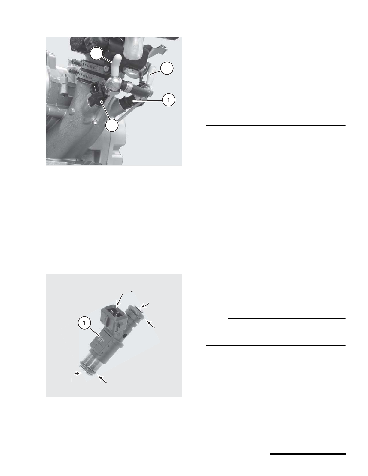
FUEL INJECTORS
N
N
TOP
)
O
G
E
)
CONNECT
O
G
Engine shown removed for clarity.
1. Left fuel injector
2. Right fuel injector
3. Fuel inlet (from fuel pump outlet)
4. Fuel outlet (to pressure regulator)
ATVs and motorcycles utilize a pair of fuel injectors
that operate (inject) simultaneously.
Pressurized fuel flows into the injectors from the
fuel pump. The fuel is delivered into the intake port
when the EC U sends voltage t o the i nj ector internal
solenoid. When th e soleno id actu ates, th e pressurized fuel sprays, through the nozzle.
The fuel injectors are positioned as close as possible to the bac k of the intak e valves. Th e spray
pattern is fixed. The length of time duration that the
injectors stay open is calcul ated b y th e ECU using
the calibration file and data received by the various
sensors.
Dynamic Test - Function
OTE :
The following procedure is based on the
assumption that there is adequate fuel supply and
pressure is available in the fuel rail .
1. Check the injector wiring harness connectors.
Make sure they are secure.
2. Check that the batter y is fully charged. The sen-
sor and actuators of the sys tem depend on accu rate voltage readings to meter the fuel.
3. Check the air filter element. If it is dirty or blocked,
this will severely impede air flow and fuel economy.
4. Check the airbox and throttle body assemblies for
possible air leak s that wo uld resul t in a le aning of
the fuel mixture.
5. Use an automotive stethoscope to determine if
each injector is working properly. You should hear
a steady clicking sound that rises and falls with
the engine speed.
NOZZL
FUEL EXIT
1. Fuel injector (left or right)
-RIN
FUEL ENTRY
-RIN
If you hear nothing, use a commercia lly available
noid light to test for voltage present at the harness
connector.
OTE :
If you do not have a stethoscope, y ou can use a
screwdriver against the injecto r and liste n through
the handle.
Static Test - Resistance
1. Disconnect the in jector, and test the resistan ce of
each injector across the terminals. If the
resistance value is out of specification, replace
the injectors as a pair.
SERVICE: Fuel, fuel injector, resistance
11.75 to 12.75 Ohms
2. Install the injector test light (one at a time) into
19
19
Page 19

© 2002 Cannondale Corporation - All Rights Reserved
each injector harness connector. Crank the
NOTE :
G
engine over. If the light flashes evenly on each
connector, voltage is available at the injectors.
3. If the light fails to flash for either injector, check
the fuel injector wiring circ uit for continuity. Co nsult the vehicle’s wiring diagram.
COOLING FAN (ATV
The positive (+) cooling fan terminal is always “hot,”
- even with the ignition switch OFF. This terminal is
connected directly to the positive battery voltage
through the main fuse.
Dynamic Test - Operate
1. Disconnect the main harne ss connector from the
cooling fan coupler.
WARNIN
Spinning fan blades can cause the fan to
jump on the workbench possibly resulting
in severe injury.
If the fan is removed from the vehic le radiator, be sure to secure the cooling fan to
the work bench. And, position the fan so
that the blades can spin freely when energized. Keep your hand clear of the blades
and wear eye protection.
The ECU switches the negative side of the cooling
fan circuit to ground when engine temperature
reaches the ON point. It breaks the ground contact
when the temperature drops to the OFF point. The
ON and OFF points are determined by the ECU
operating code.
Cooling Fan (ECU switching)
ON OFF
85°C 80°C
Consult the vehicle wiring diagram for circuit
details.
Static Test - Resistance
1. Disconnect the main harness connector from the
cooling fan coupler.
2. Measure the resistance between the two fan
leads. The resistance should be less than 1 Ohm;
if it is go to the next test.
2. Connec t a 12 V (+) battery voltage sour ce to
the red fan lead. Connect the 12V (-) lead to
the black fan lead. If the fan runs, it is OK.
Check to make sure the airflow is correct;
there is a flow direction indicator on the fan
housing. Airflow should be drawn through
the radiator from the front of the vehicle to the
back. Go to the next step.
If the fan does not operate normally (e.g.,
stops and starts, or spins slowly or not at all),
replace the fan.
3. Set the multi meter to VDC or Vdc (20 volt
range).
Connect the positive m eter probe to harness
coupler CN22 pin A.
Connect the negative mete r probe to ground.
Battery voltage should be present.
If battery voltage is not present, check the
main fuse or connections to the ba ttery. If the
main fuse and battery connections are OK,
Check for an open or short circuit in the
cooling fan circuit. Cons ult the vehicle wiring
diagram. Take corrective action.
If it is more than 1 Ohm, replace the fan.
Electrical_EFI Service Manual.fm
If the fan circuit is OK, check the coolant
sensor.
If the coolant sensor is OK, replace the ECU.
20
Page 20

8/14/02
CANNONDALE DIAGNOSTIC AND
MAINTENANCE TOOL VERSION 2.0
This section of the manual describes how to use
the Cannonda le Diagnostic and Maintena nce
software tool.
GENERAL INFORMATION
The Cannondale Diagnostic and Maintenance
Tool, Version 2.0 is a Windows-based software application enabling communication with the vehicle ECU.
Use the tool for:
• Changing the ECU operating code or “hex” fil e.
• Installing a new engine calibration file.
Refer to "Sending a cali bration file or “map” to
the ECU - “Changing a map”" starting on
page 34.
3. Follow the installation screens. When the setup
process is complete, the Cannondale Diagnostic
and Maintenance pro gram group will be installed
and a shortcut to the Cannonda le Diagnostic and
Maintenance tool wi ll be placed on the your desk top.
But, before you can use the software, you’ll need
to complete the a uthorization process by making
a telephone call and typing in an authorization
number.
• Receiving the current engine calibration file
from the vehicle ECU to the PC.
• Set the vehicle throttle body and injector
variables.
• Monitor the (vehicle) ECU operating
parameters.
• Read system faults.
A special in te r face c ab le i s ne ed ed to c on ne c t t he
PC to the vehic le onc e the soft ware i s instal le d and
authorized for use.
INSTALLATION
Installing the software
1. Insert the installation CD into the CD drive of your
computer.
Right click on the Windows START button in the
lower left corner of the screen.
Use Windows Explorer, click on the CD drive
containing the Cannondale Dealer Cal software
CD to view the file contents.
2. Double click on the Setup.exe application.
21
21
Page 21

© 2002 Cannondale Corporation - All Rights Reserved
In the Windows Explorer, double click the SecurityCode application. Or, you can access this application by clicking
on Security code.exe through the program group.
When the DealerCal window displays (see next illustration), call: Optimum Power Technology at 1-800-727-9520
(Monday through Friday, (9 am to 5 pm EST) to obtain the security code needed to activate the software.
Electrical_EFI Service Manual.fm
22
Page 22

8/14/02
Enter the Serial provided by the service r ep i n the
N
DealerCal window. Click Next.
Verifying COM port setup
’Device Manager’ Button.
5. Click the ’+’ next to ’Ports’ to expand the available
ports detail. I f there is a red ’X’ or a yellow ’!’ in
front of the Communications Port, a problem
exists with your Port Driver. Contact your Computer specialist to resolve the proble m. If there is
only a connector icon , note the Communications
Port Name (COM1, COM3, etc.) Run your DealerCal software. Under ’File->Change Port’ change
your Active Port to the above Communications
Port Name. DealerCal will retain this setting.
OTE :
NOTE: If your computer only has a USB
connection, you must purchase a “USB-to-Serial
adaptor” in order to use the DealerCal software.
COMMON PROBLEMS
Under Windows 95/98/2000/NT/ME:
1. Click ’Start’ button and select ’Settings->Control
Panel’.
2. From ’Control Panel’, Double-click ’System’.
3. From ’System Panel’, click ’Device Manager’ or
’Hardware’ tab. If clicking ’Hardware’, click the
’Device Manager’ Button.
4. Click the ’+’ next to ’Ports’ to expand the available
ports detail. I f there is a red ’X’ or a yellow ’!’ in
front of the Communications Port, a problem
exists with your Port Driver. Contact your Computer specialist to resolve the prob lem. If there is
only a connector icon, note the Communications
Port Name (COM1, COM3, etc.) Run your DealerCal software. Under ’File->Change Port’ change
your Active Port to the above Communications
Port Name. DealerCal will retain this setting.
Under Windows XP:
1. Click ’Start’ button and select ’Control Panel’.
2. From ’Control Panel’, Double-click ’Performance
and Maintenance’.
3. From ’Performance and Maintenance’, doubleclick ’System’.
4. From ’System Panel’, click ’Device Manager’ or
’Hardware’ tab. If clicking ’Hardware’, click the
Weak vehicle battery
Before using the software to communicate with the
vehicle, make sure the battery is fully charged. A low
battery can allow the ECU power relay may drop
power to the ECU which will stop any communication
between the PC and ECU.
EMS not powered-up
In order to use the tool, power to the engine management system must be ON. This is required
because the software tool “communicates” with the
ECU. If the engine management circuits are OFF, the
software ca nn ot r e ce i v e or t r an s mi t an y information
to the ECU.
Activating or turning on the engine man agement
system differs between vehicle types (ATV or Motorcycle). But, in both types, if the veh icle ECU s ens es
no activity (no engine start or communications
between the PC and ECU) for two minutes, it will
drop the signal vol tage to the EMS power r elay
shutting down power to i tself. If y ou att emp t to se nd
or receive da ta from th e ECU w hile it is “power eddown”, the “Failed to Unlock System 125” message
will display.
When this happens, the all power to the engine
management system is shut off until the engine start
button is pressed again.
23
23
Page 23

© 2002 Cannondale Corporation - All Rights Reserved
The vehicle’s lighting or starting elec tric al s yst ems
NOTE :
are isolated from the EMS power relay supplying the
ECU. Lighting can remain on if the ECU is powereddown. Or, if insufficient battery voltage is present to
hold the EMS relay on, the starter could turn over the
engine, but because the ECU is powered-down, th e
engine would not start.
Motorcycles
1. Press the ON/OFF button to O N. This will enabl e
the engine management system circuits.
2. Next, quickly press an d release the engine start
button without starting the engine. The green LED
on the interface cable wil l light when the engine
management circuits are powered up.
INTERPRETING ERROR MESSAGES
Failed to Unlock System 125
ATVs
1. Turn the ignition switch to the “ON” posi tion, then
switch the Engine RUN/OFF sw itch to the “RUN”
position.
2. Quickly press and rel ease the green start butto n
without starting the engine. The green LED on the
interface cable will light when the engine management circuits are powered up.
On ATVs, after 2 minutes of inactivity (ECU powerdown), the interface cable block green LED will
not go out. It will remain lit as long as the ATV
ignition is in the “ON” position.
The “Failed to Unlock System 125” message
means that the Ca nn ondale Diagnosti c an d Maintenance Tool was not able to communicate wi th the
vehicle ECU. There can be several causes:
• Check the interface cable at the vehicle harness
connector. Make sure the vehicle connector
pins are not bent or broken inside the
connector. Make sure the cable connector and
vehicle coupler are locked together.
• Check the interface cable attachment to the PC.
Make sure the interface cable is plugged in to
the COM port securely.
• Make sure the right COM port is selected. Refer
to "Verifying COM port setup" starting on
page 23 .
• Make sure the vehicle battery is fully ch arge d.
• Make sure the vehicle engine management
system is powered-up. See page 23.
• Click “OK” and start again.
Electrical_EFI Service Manual.fm
• If the “Failed to Unlock System” message
displays repeatedly, the vehicle ECU or
24
Page 24

8/14/02
interface cable may be damaged.
I/O Error Message
1. You wil l see th is mes s age if th e la st e ngi ne ca libr at ion fil e op ene d wit h the s oft war e i s no lon ger av ai lab le suc h
as: if it was deleted or the CD containing it has been removed from the CD drive.
OTHER MESSAGES
Progress Indicator
Whenever data is bei ng tr an sf er red between the vehicl e ECU and the PC, a progr ess i ndi cato r di sp la ys in the
upper right area of the mai n s c reen . Da ta tran sf er s sh oul d take no mo re tha n 1 mi nut e. If the pr og ress i nd icator
freezes for a long time, close the Cannondale Diagnostic and Maintenance Tool software and try again, Make sure
the cables are connected properly and that the vehicle battery is fully charged.
25
25
Page 25

© 2002 Cannondale Corporation - All Rights Reserved
Retrying Checksum
Data is transferred between the vehicle and PC in small “packets” or chunks. During the transfer process, checks
are performed by the diagnostic tool (software) to en sure th at the data is not damaged during the transfer. Each
small packet is checked during the transfer. If data errors are detected in the packet, the message “Retrying
Checksum...” will display in the progr ess indicator:
Typically, this is due to electrical “nois e” or o ther i nte rfere nc e du ring the pr oc ess. Th e di ag nostic to ol wil l k ee p
trying automatically.
Electrical_EFI Service Manual.fm
26
Page 26

8/14/02
COMMUNICATION CABLE
N
3
Connecting the communication cable
Motorcycles and ATVs have a “diagnostic” connector integrated into the main wiring harness. The
communication cable connects the PC to the vehicle
using the connector.
CAUTION:
Connect the communication cable with the
vehicle engine management system OFF.
On 2001 and 2002 Motorcycle models, the diagnostic connector is located near the ignition coil at
the top of the cylinder head. Vehicle components
must be removed to access the connector.
On 2003 Motorcycles, the diagnostic connector is
located near the main fuse under the seat.
On 2001 - 2003 ATV, the diagnostic connector is
located near the radiator shroud under the front
fender on the left side of the ATV.
1
1. Serial connector (PC)
2. LED
3. Cable
4. Connector (vehicle)
OTE :
Check the diagnostic connector pins for any
bending or damage before connecting to the
vehicle.
27
27
Page 27

© 2002 Cannondale Corporation - All Rights Reserved
CANNONDALE DIAGNOSTIC AND MAINTENANCE TOOL MAIN WINDOW
6
1
3
8
9
1. Numeric Cal ID
2. Description (saved files only - not stored in ECU)
3. Buttons
4. Throttle position sensor min and max values (from vehicle)
5. Throttle Body Leakage (also Throttle Body Offset) (Factory dyno value)
6. Fuel injector flow rate (Factory dyno value)
7. Injector offset (Factory dyno value)
8. Progress indicator
9. Button to access software version information and Cannondale internet files: http://www.cannondale.com/motorsports/tech/maps
Electrical_EFI Service Manual.fm
/
28
Page 28

8/14/02
Engine Calibration File (“Map”)
N
Identification
All Cannondale factory authorized engine calibration files are identified by a N umeric Cal ID code.
The Numeric Cal ID nu mber defines the yea r,
model, and issue sequence of any specific engine
calibratio n fil e. Th e engi ne ca libr ati on N umer ic Cal I D
number is disp l aye d i n th e to p l ef t co rn er of the Can nondale Diagnostic and Maintenance Tool main
YEAR
Reset every 10 years
(ex. 2002)
window whenever a “map” is opened or received
from the vehicle ECU. The co de number al so displays at the Numeric Cal ID field within the main
window.
Cannondale vehicles (ATVs and motorcycles) are
loaded at the factory with a model specific authorized
engine calibration file. This file can also be referred
to as the vehicle “map.”
Engine calibration files have the filename extension
“.ccf”
MODEL CODE
00 - X440s
01 - X440
02 - C440
03 - E440
30 - Cannibal
31 - Speed
32 - Blaze 440
33 - Moto 440
30202.ccf
SEQUENCE NUMBER
Assigned sequentially.
New files are
assigned the next available
number 00-99 for the model.
Always check the website
to verify that a calibration
file is authorized for use
in a particular model.
Filename extension
All Cannondale authorized
engine calibration files will
have the filename extension
".ccf."
OTE :
When a calibration file for a model is update d the SEQ number increases. However, due to continual product
evolution, the updated calibration file for the model may not be authorized for use in vehicles produced
previously. Always consult the Cannondale website for the compatibility of calibration files for a specific
vehicle VIN number.
A database of Cannondale a uthori zed eng ine ca li bration calibrations files is maintained on the Cannondale websi te so tha t service technic ians h ave
ready access to the correct factory authorized calibration files for a particular vehicle VIN.
Go to
http://www.cannondale.com/motorsports/tech/maps/.
If “Untitled” is displayed in the top left corner of the
main window, no calibration file has been opened
(from a saved file) or received from the vehicle ECU.
29
29
ECU OPERATING CODE
The ECU operating code is installed at the factory
before the engine calibration file is loaded.
The operating code also known as the “HEX” file is
like Windows 98 or XP, an “operating system” used in
many PCs. An engine calibration file can be thought
of as a program like Microsoft Excel or Netscape
Navigator, programs which run under Windows.
Page 29

© 2002 Cannondale Corporation - All Rights Reserved
ATV and Motorcycle operating codes are NOT
interchangeable.
The software tool ca n lo ad operating code ver sion
updates to the ECU.
The software does not read back the installed oper-
ating code currently in the ECU.
To install (update) an operating code
CAUTION:
When an operating code is load ed into an ECU
using the software tool, ALL information is
erased from the ECU memory including the
engine calibration file and vehicle variables
(throttle body leakage, fuel injector flow rate,
injector offset). The engine calibration file and
vehicle variables must be reinstalled into the
ECU following the operating code upda te.
2. In the main window click File - Code Download.
Receive the installed engine calibration file
FIRST. As long as nothing goes wrong with the
PC and the information is retained by the
software tool, the information can be sent to the
ECU right after the operating code update is
finished.
WRITE down the engine calibration file ID
number (Numeric Cal ID), the throttle body
leakage, fuel injector flow rate, and injector
offset before continuing.
1. On A TVs turn the ignition switch ON.
On Motorcycles, disconnect the starter solenoid
so that the engine will not turn over when the start
button is held down in a later step.
Electrical_EFI Service Manual.fm
30
Page 30

8/14/02
3. In the ECU Reprogramming Tool window, select
the operating code file to send.
Click Download.
Have an assistant p ress and contin ue to hold the
start button.
The progress indicator will display while the transfer take place.
When the transfer is complete release the start
button. C lick Close.
4. Reinstall the correct engine calibration file. Be
sure to update the v ehicle var iables befo re sending the file to the ECU.
5. On Motorcycles, be sure to reconnect the s tarter
solenoid.
31
31
Page 31

© 2002 Cannondale Corporation - All Rights Reserved
Opening a SAVED Calibration file
NOTE :
NOTE :
A saved calibration file might be one that you have
received via e-mail, downloaded from the our
website, or one that is stored on a diskette or CD.
This button functions the same way as if you click
File - Open in the top right corner of the main
window.
Once “opened,” the file is ready for installation
into the vehicle ECU.
CAUTION:
Before the saved file is sent to the ECU, be sure
to receive the vehicle variable or they will be
lost. Refer to "Receiving a calibration file
FROM THE ECU “Reading a map and
variables”" starting on page 33.
CAUTION:
Check the Numeric Cal ID field in the main
window to make sure the filename selected is
displayed. If not, go back to step 2 and repeat.
To open a saved calibration file,
In version 2.0 of the software, when the program
is launched, the last engine calibration file that
was opened is automatically open in the main
window. This feature is useful for servicing many
unit at once, however, be sure to check the engine
calibration file Numeric Cal ID code in the main
window to make sure that the right file is being
used. If not, complete steps 2 -3.
1. In the main window, click on the “OPEN
Calibration File (saved) button.
Use the Windows explorer to locate (brows e for)
the saved engine calibration file.
Select the file and click OK.
2. The file is now “loaded” to the main window.
Electrical_EFI Service Manual.fm
32
Page 32

8/14/02
Receiving a calibration file FROM THE
N
ECU
“Reading a map and variables”
By receiving the engine calibration file or the
vehicle variables from the ECU, the technical can
determine which specific engine calibration file is in
use by the vehicle and what the vehicle specific
variable are incl uded in the data file: t hrottle min/
max, Throttle body leakage (also known as offset,
fuel injector flow rate, and injector offset).
OTE :
When you “receive” an engine calibration file, a
copy of the file stored in the vehicle ECU is loaded
in the software tool main window. The vehicle
specific variables or “calibration” are also loaded.
No information is removed or deleted from the
vehicle ECU.
You can select to receive all the calibration file
from the vehicle ECU or just the thr ottle body and
injector variables or “calibrations.”
complete” message.
5. Click OK.
The vehicle calibration file has now been
copied to the Cannondale Diagnostic Tool
program. 4-SEND Calibration File (to ECU).
In case of PC failure, it is a good idea, whenever a
file is received from the vehicle ECU to write down
the throttle body and injector variables or
“calibrations.”
To receive
1. Connect the interface cable to the PC and
vehicle.
2. Open the Cannondale Diagnostic Tool software
on your PC.
3. Power-up the ECU.
4. Click the RECEIVE Calibration File (from ECU)
button.
After you click the button, the data transfer will
start. While the data is copied from the ECU to the
PC the progress in dic ato r in the upper right of the
menu will display and the LED on the interface
cable block may appear to flicker. The time
required for the transf er could v ary. It should take
place within 1 minute. When the entire data transfer process is comp let e, y ou wi ll se e the “R ec eive
33
33
Page 33

© 2002 Cannondale Corporation - All Rights Reserved
Sending a calibration file or “map” to
NOTE :
the ECU “Changing a map”
“Sending” a calibration file transfers the engine
calibration file and vehicle variables currently
open in the Cannondale Diagnostic and
Maintenance Tool main window to the vehicle
ECU.
You’ ll want to pay close attention to what engin e
calibration file is actually open before you send
the file to the ECU in the following steps.
Click the OPEN Calibration File (saved) button
to open the Open Calibration File window to
browse for a saved engine calibratio n file on your
PC. Select the filename and click OPEN.
-- or -Select File-> Open.
Sending will over-write the ECU current engine
calibration file and vehicle variabl es.
Vehicle variables (throttle min/max, throttle body
leakage (a.k.a Throttle body leakage), fuel inj ector
flow rate, and injector offset) are over-written only
if the values have been entered through the
Update Calibrations button. If no values are
entered, the vehicle variables stored in the ECU
are used.
If the interface cable is disconnected acc identally
or problems with the PC interrupt the transfer
process, the engine calibration file send process
should be start over from the beginning. Although,
it is possible to quickly reconnect the interface
cable during the transfer process, information can
be lost or damaged.
Do not experiment with calibration files!
Sending unidentified, altered, or third party
calibration files can result in severe damage to
the vehicle or affect the safe operation of the
vehicle. You could be severely injured or killed
in a resulting accident.
Always consult the Cannondale website
(www.cannondale.com) for calibration files
authorized for a specific vehicle identification
number (VIN).
You should now have an engine calibration file
“open” in the CDMT main window. Confirm that
the correct engine calibration file name is displayed in the top l eft corner of the CD MT window
and at the Numeric Cal ID field.
3. Next, make sure the vehicle engi ne management
system is powered-up . When the vehicle is powered-up, the LED on the interface cable block
should be lit.
4. Click the SEND Calibration File (to ECU) button.
If the calibration file open in the main window dif-
fers from the one current ly stor ed in the E CU, the
“Cal version different. Do you wish to procee d?”
prompt will display. Click yes to send the file. Click
cancel to exit.
If you click YES, the fi le that is open in the mai n
window will be sent to the vehicle ECU. It will
over-write the cur rent calibratio n file stored in the
ECU. During this process, the vehicle variables
currently stored in the ECU will be re tained if the
values have not been entered first using the
Update Calibrations button. If values had been
entered, they will over-write the ECU va lues during the send process. When the send has been
completed the vehicle ECU will automatically
power itself down. The LED on the interface cable
block will turn off indicating the ECU power is now
off. The calibration file just sent wi ll rem ain “op en”
in the CDMT window until the program is exited or
another calibration file is opened or received.
1. To send a cal ibra tion fil e to the v ehicle E CU, star t
by connecting the inte rfa ce c ab le to the computer
and vehicle.
2. Open the Cannondale Diagnostic and Maintenance Tool software on your P C. The CDM T program will automatically open the last engine
calibration file that was open using the program.
Electrical_EFI Service Manual.fm
Setting the throttle position sensor minimum and maximum values
The minimum and ma ximum val ues are ca ptured
and recorded into the ECU using the SET Thro ttle
Position button.
34
Page 34

8/14/02
The throttle position sensor minimum and
N
N
maximum values must be set using the CDMT
anytime the throttle body is servi ced (removed,
replaced, installed). It also must be set if the ECU
operating code is updated. Set the throttle po sition
with the engine off. When the values are set using
the tool, the minimum and maximum value actually
read into the software by the technician are checked
against a range. If any read value is out of range, the
software will report it.
are the values of the current engine calibration
file.
Again, make sure the throttle plate is com pletely
closed and click the Read Closed Voltage button.
Yo u should se e a change i n the nume ric value to
the right of the button. The change is the minimum voltage value read from the vehicle TPS
sensor when completely closed. The value can
approach zero, but should be within the typical
range indicated in the window.
OTE :
The “TPS Sensor Closed (volts)” and the “TPS
Sensor open (volts)” are displayed in the CDMT
main screen anytime a engine calibration file is
open or received from the ECU.
1. To set the throttle position, start by making sure
that the idle adjustment screw is backed off
completely. The throttle plate should be
completely shut before you continue.
Double check the throttle bellcrank after backing
the idle adjustment screw off; any slight tension in
the throttle cable can hold the plate open. Confirm
that it is closed all the way by rota ting the throttle
bellcrank with your hand - closing it firmly.
OTE :
When shutting the throttle body plate to set the
minimum value, avoid backing the adjustment
screw out too far that it falls out of the stop plate.
Next, have an assistant hold the throttle lever fully
open. While the lever is held in the “wide open
throttle” position, click the Read WOT Voltage
button. You should see a change in the n umeric
value to the righ t of the button . Tell your assistant
to release the throttle lever.
Now, both values have been read from the vehicle
TPS sensor. Y ou have two options to consider; go
2. Make sure the in ter fac e c abl e is connected to
the computer and vehicle securely.
3. Open the Cannondale Diagnostic and
Maintenance Tool software on your PC.
4. Power-up the vehicle engine management
system.
5. An engine calibration file must be open in the
CDMT main window to continue . Use the OPEN
Calibration File (saved) or use the RECEIVE
Calibration File (from ECU) button to receive the
calibration file that is currently s tored in the vehi cle ECU.
6. Click the SET Throttle Position button. The Cali-
brate Throttle window will display. When the window displays the closed voltage (minimum) and
open voltage (maximum) numeric values shown
35
35
Page 35

© 2002 Cannondale Corporation - All Rights Reserved
to the next step to learn more.
Click this butto
to
senso
u
ds
s
"
y
e
ge
e
d.
read the TP
r minim
voltage.
hese fiel
isplays the value
hat are
ready to accept
he fields initiall
how a value of th
urrently open file.
he values will chan
mmediately after th
ns at the left are
licke
7. If you click the Accept Values button, the values of
the engine calibration file currently stored in the
CDMT will change to the new ones and immediately the Send Calibrations to the ECU prompt will
display.
If you click Cancel , the new values you just read
from the vehicle will b e “forgo tten” and th e val ues
will revert back to the values of the currently open
engine calibration file; and, the CDMT main wi ndow will disp lay.
8. If you click OK, at the S end Calibrations to ECU
prompt, the Select TPS/Inj Calibrations window
will display next. Go to the next step.
If you click Cancel at the Send Calibrations to
ECU prompt, the new values will be updated in
the currently open engine calibration file and
remain until the file is c losed , ano ther ne w eng in e
calibration file ope ned or the values are c hanged
again using the Set Throttle Position button.
The Send Calibrations to the ECU prompt
9. At the Select TPS/Inj Calibr ations window, select
the values to send to th e ECU by clicking in the
check boxes. The val ues displayed in the “From
File” column are the values of the current engine
calibration file open in the CDMT. T he values of
the “From ECU” column are the old values.
Electrical_EFI Service Manual.fm
Click OK to send the val ues to the ECU. Watch
36
Page 36

8/14/02
the progress indicator. When the send is com-
N
plete, the Send complet e pr omp t will dis pl ay, click
OK.
Click Cancel and the “From File” values will not
be sent. They will remain in the currently open
engine calibration file.
CALIBRATIONS
Updating throttle body and fuel injector calibrations
The Select TPS/Inj Calibrations window
10. Power-up the vehicle ECU and click on the
MONITOR ECU Parameters b utto n to dis pla y
the ECU Monitor window.
Find the “Throttle (%) Open value.” Make
sure the ECU parameters display is in the
Continuous mode.
Adjust the idle adju stment screw so that the
“Throttle (%) O pen” value increases by 3 . F o r
example, if the value was 2.3 with the thr ottle
plate fully closed, turn the adjuster until the
value reads 5.3. If you do not open the throttle
plate the engine may no t have enough air to
idle. Opening the thr ottle plate 3% should be
enough to achieve idle.
11. Start the engine and allow to idle normally
until the vehicle to reach operating
temperature (70°C). Fi ne tune the i dle s etting
as specified for the vehicle.
The Update Calibrations window enable s you to
calibrate or “set” the vehicle specific variables which
are included in the engine calibration file data:
Throttle body leakage (offset), fuel injector flow rate,
and injector offset. These variables enable tuning the
installed map to co mpensate fo r slight ma nufacturing variations in each. The numeric values for
these variables are determined when the vehicle is
dyno-tested the factory and loaded to the calibration
file.
When a throttle body or fuel injectors are replaced the calibration information are packaged with the
new parts so that service technicians can update the
vehicle.
The calibration numeric values are part of the
“map” file and displayed in the main window.
OTE :
When a new engine calibration file “map” is sent to
the ECU the software will prompt to change the
values or use the current values stored in the old
map.
37
37
•“Throttle Body Leakage” (also called Throttle
Body Offset)
(Input range 0 - 100)
The equivalent amount, in percent, of throttle
opening required on a “perfect” throttle bo dy to
match the air flow of the vehicle's throttle body
Page 37

© 2002 Cannondale Corporation - All Rights Reserved
at the closed position.
Typical values are from 0.0 to 1.0%
•“Injector Flow Rate”
(Input range 1500 - 3000)
Typical values are from 2300-2800
The fuel injectors’ flow rate, used by the ECU to convert fuel mass in milli grams to injector pulse width in
milliseconds. The lower the flow rate, the longer the ECU has to hold the injector open to deliver a given fuel
mass. For a set of injectors, using a lower flow rate setting will deliver more fuel (richer running), and using a
higher flow rate setting will deliver less fuel (leaner running) .
•“Injector Offset”
(Input range 0.3 - 1.6)
Typical values are from 0.5 to 1.5
The amount of “dead” time of the fuel injector. The fuel injector is an electro-mechanical device, and there is
a delay from the time the electrical signal to open is delivered until the mechanical parts move and allow fuel
to flow. This delay time is added to all pulse widths. In low fuel delivery situations, the injector offset can be
the majority of the pulse width, so the proper val ue is im portant to maintain the proper a mount of fuel at l ow
throttle openings. Using a higher injector offset will deliver more fuel (richer running), and using a lower
injector offset will deliver less fuel (leaner running).
To update calibratio ns, s tart by connecti ng the i nterfa ce cable to th e com puter and ve hicl e.
To update calibrations
1. Click the “UPDATE Calibrations” button.
2. Click in the appropriate field in the window and type in the calibration (variable) values.
3. Click “OK” and the typed-in val ues will dis play in the CDM T main window. Now, you have to send these values
to the ECU for them to take effect. Click the “SEND Calibration File (to ECU)” button.
Electrical_EFI Service Manual.fm
38
Page 38

8/14/02
ECU MONITOR
1. Open the Cannondale Diagnostic Tool software
on your PC.
2. Power-up the vehicle ECU.
3. Click the MONITOR ECU Parameters button.
The ECU monitor window will be displayed.
Select “Continuous” to view live data.
Select “Hold” to take a snap shot and hold the val-
ues displayed.
Click CANCEL to exit and close the monitor.
ECU Parameters (defined)
•“RPM” - displays the engine rpm
•“Throttle Position (%)” - displays the
percentage that the throttle plate is open. This
value may not be “0” when fu lly close d or 100 %
when fully open.
Monitor selected ECU parameters with the v eh icle
engine running or with the vehicle engine off and the
ECU powered-up. It can be operated in “Continuous”
(live) or “Hold” (snap shot) mode. You can start and
run the vehicle engine with the ECU monitor active.
While the monitor window is displayed, constant
communications between the ECU and PC are
occurring - the ECU will not power itself down after 2
minutes. The moment you click CANCEL, the two
minute power-dow n t im ing wi ll start if no oth er communication is attempted.
CAUTION:
When setting idle speed with the monitor, the
engine must be at operating temperature 70°C.
•“Battery Voltage” - displays battery/ system
voltage.
•“Airbox Temperature (degC)” - air temperature
reading as measured by the ai rbox air press ure
sensor.
•“Airbox Pressure (kPa)” - airbox pressure
reading as measured by the ECU sensor.
•“Engine Temperature “(degC)” - engine
temperature reading as measured by the
coolant temperature sensor.
•“IACV Stepper Position” step position of the
Idle Air Control Valve (IACV). The ECU moves
or “steps” the valve between 0 - 255 depending
on the current engine and air temperature.
Using the ECU Monitor
To use the monitor, start by connecting the interface
cable to the computer and vehicle.
39
39
Page 39

© 2002 Cannondale Corporation - All Rights Reserved
READING FAULT CODES
N
To read fault codes
When a fault is reported, consult the fault diagnostic tables in this manual. Refer to "Fault Troubleshooting"
starting on page 42.
CAUTION:
Obtain the vehicle’s wiring diagram before attempting any testing.
OTE :
Most faults reported by the system can be corrected by examining the connector attached to the device or by
tracing circuit for an open or short circuit cond ition between the E CU conn ector s and the dev ic e con nector.
A MIL Lamp fault code (an accessory code) will di splay on units without ECU interface ac cessories. The MIL
fault does not indicate a problem with norma l engine oper atio ns, ju st the ac ce sso ries.
Once a fault has been cl ear ed th ro ugh cor re ct ive ac tion , cl os e an d r eope n the Fault Repor t wi ndo w; The E CU
does not store intermittent or one time faults. The Fault Report window will only display current faults available.
1. To read faults, make sure the communication cable is connected correctly.
2. Click the “RECEIVE Fault(s) (From ECU)” button in the main window.
The Fault Report window will display with a list of faults the ECU was encountering when the button was
clicked.
These are “live” faults not stor ed faults. The GP Control MC1000 ECU programmi ng does not store faults in
memory, therefore the faults displayed in the window are the faults the ECU re ports when th e F ault Repo rt but-
Electrical_EFI Service Manual.fm
40
Page 40

8/14/02
ton was pressed. The Fault Re port window does
not constantly update fault conditions.
Fault Report window
The Fault Report window sample above was
taken while the C annondale Diagnostic Tool was
connected to an 2002 X440s motorcycle. This
vehicle does not have a c ool in g fan . T he “C oo li ng
Fan open fault” will report when the tool is c onnected to a motorcycle, ho wever, it can be disregarded. Also for the sample fault report above, we
temporarily disconnected the air temperature sensor - notice the “Air temp sensor high fault” that
was reported.
Connect the inte rface cable to the co mputer and
vehicle.
41
41
Page 41

© 2002 Cannondale Corporation - All Rights Reserved
FAULT TROUBLESHOOTING
Consult the following troubleshooting tables when
diagnosing a fault reported by the Cannondale Diagnostic and Maintenance Tool Fault Report window
function. Refer to "Reading Fault Codes" starting on
page 40.
SENSOR SUPPLY VOLTAGE
Fault Reported Possible Cause Action
ECU damaged
Sensor power supply fault
wiring fault
Pinpoint Tests
Test Result Action
1. Check wire and terminal
integrity:
- P1 B3
OK
Faulty Correct and go to Test 4.
temperature sensor, and coolant sensor,
and go to Te st 2.
Disconnect ECU and go to Test 1.
Disconnect throt tle positi on senso r, air
2. Check for harness short
circuit
- P1 B3 to P1 E4
3. With igni tion ‘ON’ c heck
voltage at:
- P1 B3 at the back of the connector locate wire (70 White)
or at CN3 pin B.
4. Reconnect harness, run
engine check for presence of
fault.
Circuit Diagram
OK Reconnect ECU and go to Test 3.
Short circuit
4.5 to 5.5v Go to Test 4.
Faulty Replace the ECU, go to Test 4.
OK Done
Fault still present Contact Cannondale Dealer Service.
Locate short in harness and correct and
go to Test 4.
Electrical_EFI Service Manual.fm
42
Page 42

8/14/02
SYSTEM VOLTAGE
Fault Reported Possible Cause Action
Battery voltage low fault
Wiring/ Stator/ Regulator/
Battery
minimum voltage 12.8v.
Check battery voltage at battery;
Disconnect ECU and go to Test 1.
Battery voltage high fault Regulator
Ensure regulato r outp ut vol tage is withi n
specified range.
Pinpoint Tests
Test Result Action
1. Check wire and termina l
OK Go to Test 2.
integrity:
- P2 E1
2. With igniti on ‘on,’ check
voltage at:
- P2 E1
3. Run engine check for
presence of fault.
Faulty Correct and go to Test 3.
Same as battery voltage Go to Test 3.
Less than battery voltage
Locate and correct wiring fault; go to T est
3.
OK Done
Fault still present Contact Cannondale Dealer Service.
Circuit Diagram
43
43
Page 43

© 2002 Cannondale Corporation - All Rights Reserved
FUEL PUMP
Reported Fault Possible Cause Action
Damaged fuel pump
Fuel pump short
(internal short circuit), harness
short circuit, damaged ECU
"Fuel Pump" starting on page 44.
Component test fue l pump. Refer to
Damaged fuel pump
(internal open circuit) harness
Make sure fuel pump connector and fuel
pump terminals are secure.
open circuit, harness con-
Fuel pump open
nector disconnec ted or ter-
Verify good main fuse.
minals at pump loose or disconnected, open circuit to
Disconnect ECU and go Test 1.
battery 12V(+).
Pinpoint Tests
Test Result Action
1. Check wire and terminal
integrity:
- P1 H1
2.Check for short circuit
between:
- P1 H1 to ground
OK
Faulty Locate and correct and go to Test 2.
Open Go to Test 3.
Shorted
Disconnect the fuel pump and go to Test
2.
Locate and correct wiring fault; go to Test
7.
Continuity Go to Test 4.
3. Check continuity between:
- P1 H1 and CN16 pin B
Open
Locate and correct wi rin g fa ult; go to Test
5.
4. Reconnect ECU, press
engine start button, wait 5
seconds and check for short
circuit between:
- CN16 B to ground
5. Verify 12V (+) at CN16 pin A
6. Reconnect the ECU a nd
fuel pump. Verify that pump runs
briefly (3 seconds) when engine
start button is pressed.
7. Run engine and check for
presence of fault.
Circuit Diagram
Open Go to Test 5.
Shorted Replace ECU, go to Test 7.
OK Go to Test 6.
None
Locate and correct wi rin g fa ul t; go to Test
6.
OK Go to Test 7.
Faulty Replace ECU and go to Test 7.
OK Done
Fault still present Contact Cannondale Dealer Service.
Electrical_EFI Service Manual.fm
44
Page 44

8/14/02
IGNITION COIL
Fault Possible Cause Action
Damaged ignition coil or
Coil short fault
ECU, harness short circuit,
coil connector disconnected
or damaged
Pinpoint Tests
Test Result Action
"Ignition Coil" starting on page 45.
secure.
Component test ignition coil. Refer to
Check ignition coil harness connector is
Disconnect ECU and go to Test 1.
1. Check wire and terminal
integrity:
- P2 H1
2. Check resistance value:
Disconnect diagnostic connector CN10, lighting co nnector
CN26 (Motorcycle only), remove
EMS power relay. Measure
between relay socket terminal
30 and P2 H1.
3. Check wire for short circuit
between:
- P2 H1 to ground
4. Check wire continuity
between:
EMS power relay so cket terminal 30 and CN8 pin 2.
5. Check wiring for short circuit
between:
EMS power relay so cket terminal 30 and P2 H1
OK Go to Test 2.
Faulty Locate and correct and go to Test?.
0.6 Ohms Disconnect ignition coil and go to Test 3.
Open circuit Go to Test 4.
Short circuit Disconnect ignition coil and go to Test 5.
Short circuit
Locate and corr ect wi r ing f au lt an d go to
Test 7.
Open circuit Go to Test 7.
Continuity Go to Test 6.
Open circuit Correct wiring fault and go to Test 7.
Short circuit
Locate and corr ect wi r ing f au lt an d go to
Test 7.
Open circuit Go to Test 6.
6. Check ignition coil primary
resistance across coil pins 1 and
2
7. Reconnect ECU, run engine
check for presence of fault.
Circuit Diagram
0.6 Ohms primary Go to Test 7.
Faulty Replace coil, go to Test
OK Done
Fault still present Contact Cannondale Dealer Service.
45
45
Page 45

© 2002 Cannondale Corporation - All Rights Reserved
COOLING FAN (ATV ONLY)
Fault Possible Cause Action
"Cooling Fan (ATV Only)" starting on
page 46.
Damaged cooling fan or
Cooling fan short fault,
Cooling fan open fault
ECU, harness short circuit,
fan connector disconnected or
damaged
Pinpoint Tests
Test Result Action
Refer to "Coolant Sensor" starting on
page 53.
is secure.
Component test the cooling fan. Refer to
Component test the coolant sensor.
Check that cooling fan harness connector
Verify good main fuse.
Disconnect ECU and go to Test 1.
1. Check wire and terminal
integrity:
- P2 G1, P2 G2
2. Check wire for short circuit:
- P2 G1 to ground
- P2 G2 to ground
3. Check wire continuity
between:
- P2 G1 and CN22 pin B
4. Verify 12V(+) at CN22 pin A
5. Reconnect the cooling fan
and ECU and verify proper fan
operation (on at 85°C, off at
80°C coolant temperature).
Verify correct airflow.
7. Run engine and check for
presence of fault.
OK Disconnect cooling fan and go to Test 2.
Faulty
Locate and cor rec t w iri ng fa ul t a nd g o t o
Test 5.
OK Go to Test 3.
Short circuit
Locate and correct wire fault a nd go to
Test 5.
OK Go to Test 4.
Open circuit Correct wiring fault, go to Test 5.
OK Go to Test 5.
None
Locate and correct wi rin g fa ul t, go to Test
6.
OK Done
Faulty Replace ECU and go to Test 7.
OK Done
Fault still present Contact Cannondale Dealer Service.
Circuit Diagram
Electrical_EFI Service Manual.fm
46
Page 46

8/14/02
FUEL INJECTORS
Fault Possible Cause Action
Damaged injector or ECU,
Injector A short fault (left)
harness short circuit
Injector B short fault (right)
Injector A open fault (left)
Injector B open fault (right)
Pinpoint Tests
Test Result Action
1. Check wire and terminal
integrity:
- P1 H2
- P1 H3
2. Check resistance value:
Motorcycle
Disconnect diagnostic connector
CN10, lighting connector CN26,
remove EMS power relay.
Measure between relay socket
terminal 30 and:
- flooding indicates short
circuit
Damaged injector, injector
connector disconnected or
damaged, harness open
circuit
- misfire indicates open
circuit
OK Go to Test 2.
Faulty
12.25
± 0.50 Ohms at 20 ±
2°C
Open circuit Go to Test 4.
Component test the injector. Refer to
"Fuel Injectors" starting on page 19.
Check that injector harness connector is
secure.
Disconnect ECU and go to Test 1.
Locate and corr ect wi r ing f au lt an d go to
Test 7.
Disconnect relevant injector and go to
Test 3.
- P1 H2 (Left injector)
- P1 H3 (Right injector)
ATV
Disconnect the ignition coil,
diagnostic connector CN10,
switch engine s top button to
OFF position. Measure between
P2 E1and:
- P1 H2 (Left injector)
- P1 H3 (Right injector)
Short circuit
47
47
Disconnect relevant injector and go to
Test 5.
Page 47

© 2002 Cannondale Corporation - All Rights Reserved
FUEL INJECTORS
3. Check wire for short circuit
- P1 H2 to ground
- P1 H3 to ground
4. Check wire continuity:
Motorcycle
Disconnect diagnostic connector
CN10, lighting connector CN26,
remove EMS power relay.
Measure between relay socket
terminal 30 and:
- relevant injector pin 1
- P1 H3 to CN6 pin 2 (Right
injector)
- P1 H2 to CN7 pin 2 (Left
injector)
ATV
Disconnect the ignition coil,
diagnostic connector CN10,
switch engine st op button to
OFF position. Measure between
P2 E1and:
OK Go to Test 7.
Short circuit
Locate and correct wire fault a nd go to
Test 7.
Continuity Go to Test 6.
Open circuit
Locate and correct wire fault a nd go to
Test 7.
- relevant injector pin 1
- P1 H3 to CN6 pin 2 (Right
injector)
- P1 H2 to CN7 pin 2 (Left
injector)
Electrical_EFI Service Manual.fm
48
Page 48

8/14/02
FUEL INJECTORS
5. Check short circuit:
Motorcycle
Disconnect diagnostic connector
CN10, lighting connector CN26,
remove EMS power relay.
Measure between relay socket
terminal 30 and:
- P1 H3
- P1 H2
ATV
Disconnect the ignition coil,
diagnostic connector CN10,
switch engine s top button to
OFF position. Measure between
P2 E1and:
- P1 H3
- P1 H2
6. Check inj ector resistance:
- relevant injector across ter-
minals 1 to 2
OK Go to Test 6.
Short circuit
12.25
± 0.50 Ohms at 20 ±
2°C
Faulty Replace injector go to Test 7.
Locate and correct wiring fault proceed to
Test 7.
Go to Test 7.
7. Run engine and check for
presence of fault.
Circuit Diagram
OK Done
Fault still present Contact Cannondale Dealer Service.
49
49
Page 49

© 2002 Cannondale Corporation - All Rights Reserved
THROTTLE POSITION SENSOR (TPS)
Fault Possible Cause Action
Throttle position se nsor high
fault
Throttle position sensor low
fault
Damaged TPS sensor,
ECU, harness short or open
circuit, TPS se ns or c on nec to r
disconnected or damaged
Component test the TPS sensor.
Check that sensor harness connector is
secure.
Disconnect ECU and go to Test 1.
Pinpoint Tests
Test Result Action
1. Check wire and terminal
OK Disconnect TPS sensor and go to Test 2.
integrity:
- P1 B3
Locate and cor rec t w iri ng fa ul t a nd g o t o
Test 5.
- P1 E3
Faulty
- P1 B4
2. Check for short circuit
OK Go to Test 3.
between:
Locate and cor rec t w iri ng fa ul t a nd g o t o
Test 5.
- P1 E3 to ground
Short circuit
3. Check cable continuity:
- P1 E4 to CN3 pin A
- P1 E3 to CN3 pin C
- P1 B3 to CN3 pin B
4. Check cable for short circuit:
- P1 E3 to P1 B3
- P1 E3 to P1 E4
5. Reconnect harness, run
engine and check for presen ce
of fault.
Circuit Diagram
OK Go to Test 4.
Open circuit
OK
Short circuit
Locate and cor rec t w iri ng fa ul t a nd g o t o
Test 5.
Replace throttle position sensor, go to
Test 5.
Locate and cor rec t w iri ng fa ul t a nd g o t o
Test 5.
OK Done
Fault still present Contact Cannondale Dealer Service.
Electrical_EFI Service Manual.fm
50
Page 50

8/14/02
AIR TEMPERATURE SENSOR
Fault Possible Cause Action
Damaged air temperature
Air temp sensor high fault
sensor, ECU, harness short or
open circuit , sensor con-
Air temp sensor low fault
nector disconnected or
damaged
Pinpoint Tests
Test Result Action
sensor.
secure.
Component test the air temperature
Check that sensor harness connector is
Disconnect ECU and go to Test 1.
1. Check wire and terminal
integrity:
- P1 D1
- P1 E4
2. Check resistance value:
- P1 D1 to P1 E4
(verify value at temperature
tested; see table)
3. Check wire continuity:
- P1 D1 to CN5 pin 2
- P1 E4 to CN5 pin 1
4. Check for wire short circuit:
- P1 D1 to P1 E4
OK Disconnect TPS sensor and go to Test 2.
Faulty
OK
Locate and corr ect wi r ing f au lt an d go to
Test 7.
Disconnect temperature sensor and go to
Test 6.
Open circuit Go to Test 3.
Short circuit
Disconnect temperature sensor and go to
Test 4.
OK Go to Test 5.
Open circuit
Locate and corr ect wi r ing f au lt an d go to
Test 7.
OK Go to Test 5.
Short circuit
Locate and corr ect wi r ing f au lt an d go to
Test 7.
5. Check sensor resistance:
- CN5 pin 1 to pin 2
(verify value at temperature
tested; see table)
6. Check wire for short circuit”
- P1 D1 to ground
7. Reconnect harness, run
engine and check fo r prese nce
of fault.
OK Go to Test 7.
Faulty Replace sensor, go to Test 7.
OK Go to Test 7.
Short circuit
Locate and corr ect wi r ing f au lt an d go to
Test 7.
OK Done
Fault still present Contact Cannondale Dealer Service.
51
51
Page 51

© 2002 Cannondale Corporation - All Rights Reserved
AIR TEMPERATURE SENSOR
Circuit Diagram
Air Temperature Sensor Resist ance Range
Resistance
(ohms)
15071 -20 -4 1700 30 86 331 80 176
11739 -15 5 1414 35 95 287 85 185
9215 -10 14 1181 40 104 250 90 194
7290 -5 23 992 45 113 219 95 203
5808 0 32 837 50 122 192 100 212
4659 5 41 710 55 131 169 105 221
3763 10 50 604 60 140 149 110 230
3058 15 59 517 65 149 132 115 239
2500 20 68 444 70 158 118 120 248
2056 25 77 382 75 167 N/A N/A N/A
Temp.
(deg. C)
Temp.
(deg. F)
Resistance
(ohms)
Temp.
(deg. C)
Temp.
(deg. F)
Resistance
(ohms)
Temp.
(deg. C)
Temp.
(deg. F)
Electrical_EFI Service Manual.fm
52
Page 52

8/14/02
COOLANT SENSOR
Fault Reported Possible Cause Action
Damaged coolan t temper-
Engine temp sensor high fault
ature sensor, ECU, harness
short or open circu it, sensor
Engine temp sensor hi fault
connector disconnected or
damaged
Pinpoint Tests
Test Result Action
sensor. Refer to "Coolant Sensor" starting
on page 53.
secure.
Component test the coolant temperature
Check that sensor harness connector is
Disconnect ECU and go to Test 1.
1. Check wire and terminal
integrity:
- P1 B2
- P1 E4
2. Check resistance value:
- P1 B2 to P1 E4
(verify value at temperature
tested; see table)
3. Check wire continuity:
- P1 B2 to CN4 pin 2
- P1 E4 to CN4 pin 1
4. Check for wire short circuit:
- P1 B2 to P1 E4
5. Check sensor resistance:
- CN4 pin 1 to pin 2
(verify value at temperature
tested; see table)
OK Go to Test 2.
Faulty
OK
Locate and corr ect wi r ing f au lt an d go to
Test 7.
Disconnect temperature sensor and go to
Test 6.
Open circuit Go to Test 3.
Short circuit
Disconnect temperature sensor and go to
Test 4.
OK Go to Test 5.
Open circuit
Locate and corr ect wi r ing f au lt an d go to
Test 7.
OK Go to Test 5.
Short circuit
Locate and corr ect wi r ing f au lt an d go to
Test 7.
OK Go to Test 7.
Faulty Replace sensor, go to Test 7.
6. Check wire for short circuit”
- P1 B2 to ground
7. Reconnect harness, run
engine and check fo r prese nce
of fault.
Circuit Diagram
OK Go to Test 7.
Short circuit
Locate and corr ect wi r ing f au lt an d go to
Test 7.
OK Done
Fault still present Contact Cannondale Dealer Service.
53
53
Page 53

© 2002 Cannondale Corporation - All Rights Reserved
Coolant Sensor Resistance Range
Resistance
(ohms)
45313 -40 -40 2500 20 68 322 80 176
34281 -35 -31 2057 25 77 280 85 185
26114 -30 -22 1707 30 86 243 90 194
20003 -25 -13 1412 35 95 213 95 203
15462 -20 -4 1175 40 104 187 100 212
12002 -15 5 988 45 113 164 105 221
9397 -10 14 834 50 122 144 110 230
7415 -5 23 703 55 131 127 115 239
5896 0 32 595 60 140 113 120 248
4712 5 41 508 65 149 100 125 257
3792 10 50 436 70 158 89 130 266
3069 15 59 374 75 167 N/A N/A N/A
Temp.
(deg. C)
Temp.
(deg. F)
Resistance
(ohms)
Temp.
(deg. C)
Temp.
(deg. F)
Resistance
(ohms)
Temp.
(deg. C)
Temp.
(deg. F)
Electrical_EFI Service Manual.fm
54
Page 54

8/14/02
IDLE AIR CONTROL VALVE (IACV)
Fault Reported Possible Cause Action
Damaged idle air control
Stepper motor fault
Pinpoint Tests
Test Result Action
valve, ECU, harness short or
open circuit, IACV connector
disconnected or damaged
Air Control Valve (IACV)" starting on
page 55.
Component tes t th e IACV. Refer to "Idle
Check that harness connector is secure.
Disconnect ECU and go to Test 1.
1. Check wire and terminal
integrity:
- P1 E1
- P1 E2
- P1 F1
- P1 F2
2. Check resistance:
- P1 E1 to P1 F1
- P1 E2 to P1 F2
3. Check cable for short circuit:
- P1 E1 to ground
- P1 E2 to ground
- P1 F1 to ground
- P1 F2 to ground
4. Check cable continuity:
- P1 E1 to CN25 pin A
- P1 E2 to CN25 pin B
- P1 F1 to CN25 pin C
- P1 F2 to CN25 pin D
OK Go to Test 2.
Faulty
53
± 10% Ohms
Open circuit Go to Test 4.
Short circuit Disconnect IACV and go to Test 5.
OK Go to Test 7.
Short circuit
OK Go to Test 6.
Open circuit
Locate and corr ect wi r ing f au lt an d go to
Test 5.
Disconnect the IAVC and go to Test 3.
Locate and corr ect wi r ing f au lt an d go to
Test 7.
Locate and corr ect wi r ing f au lt an d go to
Test 7.
5. Check cable for short circuit:
- P1 E1 to P1 F1
- P1 E2 to P1 F2
Check IACV resistance:
- IACV pin A to pin D
- IACV pin B to pin C
7. Reconnect harness, run
engine and check fo r prese nce
of fault.
Circuit Diagram
OK Go to Test 6.
Short circuit
53
± 10%
Faulty Replace IACV, go to Test 7.
OK Done
Fault still present Contact Cannondale Dealer Service.
55
55
Locate and corr ect wi r ing f au lt an d go to
Test 7.
Go to Test 7.
Page 55

© 2002 Cannondale Corporation - All Rights Reserved
CRANKSHAFT POSITION SENSOR
Fault Reported Possible Cause Action
Check that harness connector is secure.
Crank tooth sync fault
Damaged or contaminated
crankshaft po sition sensor,
damaged ECU, harness short
or open circuit, IACV connector disconnected or
damaged
Check sensor air gap: 0.5 to 1.0 mm
Check for damaged flywheel teeth.
Check flywheel runout or play.
Disconnect ECU and go to Test 1.
Pinpoint Tests
Test Result Action
1. Check wire and terminal
OK Disconnect sensor and go to Test 2.
integrity:
- P1 A1
- P1 B1
2. Check cable for short circuit:
- P1 A1 to ground
- P1 B1 to ground
3. Check cable continuity:
- P1 A1 to CN2 pin 2
- P1 B1 to CN2 pin 1
Faulty
OK Go to Test 3.
Short circuit
OK Go to Test 4.
Open circuit
Locate and cor rec t w iri ng fa ul t a nd g o t o
Test 8.
Locate and cor rec t w iri ng fa ul t a nd g o t o
Test 8.
Locate and cor rec t w iri ng fa ul t a nd g o t o
Test 8.
4. Check cable for short circuit:
- P1 E1 to P1 F1
- P1 E2 to P1 F2
5. Check cable continuity:
- Sensor cable screen to (frame)
ground
6. Check sensor resistance:
Sensor pin 1 to pin 2
7. Check crank toothed wheel
- Damaged teeth
- Magnetic debris contamination
8. Reconnect harness, run
engine and check for presen ce
of fault.
OK Go to Test 6.
Short circuit
Locate and cor rec t w iri ng fa ul t a nd g o t o
Test 8.
OK Go to Test 7.
Open circuit
Locate and cor rec t w iri ng fa ul t a nd g o t o
Test 8.
532 to 588 Ohms Go to Test 5.
Faulty Replace sensor and go to Test 8.
OK Go to Test 8.
Faulty
Clean / replace toothed wheel, go to Test
8.
OK Done
Fault still present Contact Cannondale Dealer Service.
Electrical_EFI Service Manual.fm
56
Page 56

8/14/02
COMPONENT TESTING (NON-EFI)
N
BATTERY
1. Filling electrolyte properly, Charging (times and
rates).
2. Load testing using a comme rcially available load
tester.
3. Installation
Test for continuity between both black wires; there
should be continuity.
Test for cont inuity between both red wires; there
should be continuity.
Test for shor t circuit b etween on e of the r ed wires
and the two blacks; there s hould be no contin uity.
Repeat the test for the other red wire. There
should be no continuity.
4. Test for continuity between both black output
wires and the rectifier/regulator housing. There
should be no continuity.
Washers?
Loctite
Torque
RECTIFIER /REGULATOR
OTE :
If vehicle is equipped with single phase rectifier/
regulator, complete the steps described, but omit
the references made to the third wire (three phase
rectifier/regulator).
Dynamic Test
1. Set multi-meter to DC V or Vdc (DC volts ); switch
the range to 20 or 50V. Connect the multi meter
leads to the battery terminals. Start and rev the
engine up to 3000 r/min. Check the battery
voltage.
If the voltage is higher tha n 13.5V, rev the engine
to 5000 r/min. Check the reading on the meter, if it
is lower than 14.8V, the charging system is OK.
If the voltage at 3000 r/min. is lower than 13 .5V,
go to the static test.
Static Test
5. Connect the positive mu lti meter probe to the red
output wire of the recti fier/regulator. Connect the
black multi meter to the yell ow input wire. Rep eat
this procedure for each wire.
If an OL (no continuity) is indicated in all three yellow wires, go to the next step.
If you have conti nuity on any of the three yellow
wires, replace the rectifier/regulator with a new
one.
6. Connect the negative multi meter probe to the red
output wire of the recti fier/regulator. Connect the
positive probe to a yellow input wire. Check the
reading. Repeat the test for each wire.
If a reading around 1 to 1.5 Ohms is obtain ed on
all wires, go to the next step.
If an OL (no continu ity) is obtained on any wire,
replace the rectifier/regul ato r with a new one.
7. Connect the negative multi meter probe to the
negative output wire of the rectifier/regulator.
Connect the positive multi meter probe to one yellow wire. Check the r ead ing . Repeat for all y ellow
wires.
If an OL (no continuity) is on all three wires is
obtained, go to the next step.
If you have continuity on any wire, replace the
rectifier/regulator with a new one.
1. Disconnect the rec tifier/regul ator from the v ehicle
wiring harness.
2. Switch the multi meter to Ohms (lowest ra nge).
3. If the rectifier regul ator has two red output wires
and two black output wires:
57
57
8. Connect the positive multi meter probe to the negative output wire of the rectifier/regulator. Connect
the negative multi met er probe to one ye llow wire
and check the reading. R epeat for the other two
yellow wires.
If a reading around 1 to 1.5 Ohms is obtain ed on
all three tests, the rectifier/regulator is OK.
Page 57

© 2002 Cannondale Corporation - All Rights Reserved
If an OL (no continuity) is obtained on any one of
NOTE :
the three tests, replace the rectifier/regulator.
exist in the rectifier/regulator. Test the rectifier/
regulator.
Stator
If vehicle is equipped with a single phase stator,
complete the steps described, but omit the
references made to the third wire (three phase
stator).
Static Test
1. Disconnect the stator connector.
2. Set multi meter to the lowest Ohms setting.
Measure the resistance between all three wires
coming from the stator. Start with one wire and
read resistance between it and the other two.
Repeat for remaining two wires.
If all readings are within 0.5 to 2.0 Ohms, go to
the next step.
If one of the readings is lower than 0.5 Ohms or
higher than 2.0 Ohms, replace the stator.
Connect one of the multi met er lead s up to one of
the three yellow wires. Connect the other multi
meter lead up to the crank case or to a gro unding
point on stator core if it has been removed. Check
the reading on th e meter. Make sure the co nnection of the lead to the crankcase or stator core is a
good one.
No reading or “OL” displayed, go to the next step.
FLYWHEEL
Inspection Points
1. Check for contact between the installed flywheel
and crankshaft position sensor. Make sure the
specified sensor air gap is maintaine d throughou t
flywheel rotation.
SERVICE:
1. Inspect the flywheel for cracking, damaged
magnetic material, key groove, and woodruff
(crankshaft) key.
2. Check flywheel key location. Make sure the hub
has not spun in th e alu mi num bo dy. The key “cut”
in the hub shoul d be aligned with the “C” in the
molded “Cannondale” text.
START BUTTON (ATV & MOTORCYCLE)
1. Disconnect the engine start button from the m ain
harness.
2. Test fo r continuity between the two leads. There
should be no continuity.
3. Press and hold the button and test for continuity.
There should be continuity when the button is
pressed.
If you have any readin g between 100 Ohms an d
zero Ohms, replace the stator.
Dynamic Test - AC Output
1. Switch the multi meter to the AC voltage (range at
least 100 VAC). Make sure you do not sw itch to
DCV or Vdc by mistake. Conne ct the multi meter
leads between two of the yell ow wires emerging
from the stator. Start the engine and bring to 5000
r/min. Check the reading on the meter. Switch one
of the multi meter leads to another yellow wire
and check the reading again.
If three equal readings are obtained, all higher
than 50 VAC, the stator is ok. A problem may
Electrical_EFI Service Manual.fm
ENGINE STOP BUTTON
1. Disconnect the engine sto p button from the main
harness.
2. Test fo r continuity between the two leads. There
should be continuity.
3. Press and hold the button and test for continuity.
There should be no co ntinuity when the butto n is
pressed.
58
Page 58

8/14/02
ENGINE STOP SWITCH (ATV)
OFF
RUN
RUN W/LTS
GREEN VI OLET YELLOW
STARTER SOLENOID
1. Disconnect the engine stop s witch from the main
harness.
2. Slide the switch to the RUN position. There
should be continuity between the two switch
leads.
3. Slide the switch to the OFF position. There should
be no continuity.
CLUTCH LEVER SWITCH (ATV)
1. Disconnect the cl utch switch connector from the
switch body.
2. Test for continuity between the switch terminals.
There should be no continuity.
3. Pull in the clutch lever and test for continuity
between the switch terminals. There should be
continuity.
Dynamic Test - Solenoid Function
1. Press the engine start button. On ATVs, the
additional step of turning the ignition key ON and
pulling in the clutch lever is required before
pressing the start button.
The solenoid is no rm al if the so len oi d clic k s wh en
the start button is pressed.
If you do not hear a “CLICK”, go to the next test.
Static Test - Harness Voltage
1. Disconnect the solenoid from the main wiring
harness.
2. On ATVs, turn the ignition key ON and pull in the
clutch lever.
Set multi meter to DCV 20V range and connect
the positive meter lead to connector pin A; connect the negative me ter lead to connector pin B.
Press the engine s tar t bu tton . T he rea d in g should
be same as battery voltage (12.5 to 13.0Vdc).
KEY SWITCH
1. Disconnect the key switch connectors from the
main harness.
2. Rotate the key to the OFF position.
Set the multi meter to Ohms. Test for continuity
between any of the switch leads. There should be
no continuity between any of the leads.
3. Rotate the key to the ON po sition. There should
be continuity between the green and violet leads .
There should be no c on tin uity between the yellow
lead and the green or violet.
Rotate the switch to th e “ON w/ Lights” position.
There should be contin uity between all leads.
If no voltage is detected, check the main fuse.
If the main fuse is OK, check the starti ng circuit
for an open or short circuit. Take corrective action.
Consult the vehicle wiring diagram.
3. Set multi meter to Ohms. Connect the positive
meter lead to solenoid connector harness pin B
and the negative meter lead to ground. There
should be continuity.
If an open circuit is detec ted, consult the vehicle
wiring diagram.
Static Test - Resistance
1. Disconnect the solenoid from the main wiring
harness.
2. Measure the resistanc e of the solenoid c oil at the
harness connector.
SERVICE: Solenoid coil resistance
5.0 Ohm
59
59
Page 59

© 2002 Cannondale Corporation - All Rights Reserved
Operati on Test
G
1. Disconnect the solenoid from the main wiring
harness.
2. Connect the positive l ead of a 12V ba ttery power
source to the sol enoid coil posi tive lead or terminal (pin A) and the ne gative lead of the 12V battery power source to the solenoid coil negative
lead or terminal (pin B).
There should be con tinuity be tween the la rge terminals while the battery source is conne cted, an d
no continuity when the bat tery source is disconnected.
STARTER MOTOR
harness starting circ uits f or shor t or op en ci rcuits .
Consult the vehicle wiring diagram.
If the starter motor d oes n ot turn, c onfir m tha t the
engine can be turned o ve r m anu all y. If the engine
does not turn over manually, there is a internal
engine problem. Take corrective action.
If the engine turns over manually, the starter is
damaged; replace it.
FUSES
When a fuse blows repeatedly, it usually indicates a
short circuit or current overload in the electrical
system. The problem could be intermittent or constant.
Press the engine start button. On ATVs, the additional step of turning the ig niti on key O N and pulling
in the clutch lever is required before pressing the
start button.
The starter motor is normal if the engine turns over
when the start button is pressed.
If the engine does not turn over:
- Check for loose battery cables or open circuit in
battery cables.
- Check for loose solenoid terminals or connectors
- Test the solenoid opera tio n
3. Disconnect the positive cable from the positive
starter terminal. Press th e en gin e s tart button. On
ATVs, the additional step of turning the ignition
key ON and pull ing in the clutc h lever is req uired
before pressing the start butt on. Test for 12V (+)
voltage between the starter cable and ground.
There should be 12V (+) when the button is
pressed.
If no voltage is found and the solenoid is OK,
check the vehicle wi ring harness starting circu its
for short or open circu its. Consult the ve hicle wiring diagram.
If voltage is present, go to next step.
1. To inspect the fuse, remove the fuse from the
holder and inspect it.
(1)
REPLACE
WARNIN
Use only specified fuse rating. An electrical fire or vehicle damaged can result if a
fuse rating other than specified is used.
Using other materials in place of the fuse
will cause damage to system.
4. Connect the starter motor positive terminal
directly to the vehicle battery positive terminal
with a heavy lead similar in size to starter motor
harness cable.
If the starter motor turns, check th e vehicl e wirin g
Electrical_EFI Service Manual.fm
60
Page 60

Printed : 8/14/02
INTRODUCTION - - - - - - - - - - - - - - - - - - - - - - 3
Important Notice - - - - - - - - - - - - - - - - - - 3
About the manual - - - - - - - - - - - - - - - - - 3
Comments? - - - - - - - - - - - - - - - - - - - - 3
IMPORTANT MANUAL INFORMATION- - - - - - - - - - - 4
ENGINE MANAGEMENT SYSTEM (EMS) - - - - - - - - - 6
Engine Control Unit (ECU) - - - - - - - - - - - - - 6
ECU Programming - - - - - - - - - - - - - - - - - 7
Servicing connectors and couplers - - - - - - - - - 9
Barometric pressure sensor - - - - - - - - - - - 10
Throttle position sensor (TPS) - - - - - - - - - - 10
Coolant temperature sensor - - - - - - - - - - - 12
Air temperature sensor - - - - - - - - - - - - - - 12
Crankshaft position sensor - - - - - - - - - - - - 13
Idle Air Control Valve (IACV) - - - - - - - - - - - 14
Ignition coil- - - - - - - - - - - - - - - - - - - - 15
EMS Power Relay - - - - - - - - - - - - - - - - 15
Fuel pump and fuel pressure regulator - - - - - - 17
Cooling Fan (ATV - - - - - - - - - - - - - - - - 20
CANNONDALE DIAGNOSTIC AND MAINTENANCE TOOL
VERSION 2.0 - - - - - - - - - - - - - - - - - - - - - - - 21
General Information - - - - - - - - - - - - - - - 21
Installation - - - - - - - - - - - - - - - - - - - - 21
In the Windows Explorer, double click the SecurityCode
application. Or, you can access this application by clicking
on Security code.exe through the program group. - - 22
Common Problems- - - - - - - - - - - - - - - - 23
Interpreting Error Messages - - - - - - - - - - - 24
Other Messages - - - - - - - - - - - - - - - - - 25
Communication cable - - - - - - - - - - - - - - 27
Cannondale Diag nos tic and M ai nte nan ce tool Main Window - - - - - - - - - - - - - - - - - - - - - - - - 28
ECU Operating code - - - - - - - - - - - - - - - 29
Calibrations - - - - - - - - - - - - - - - - - - - 37
ECU Monitor - - - - - - - - - - - - - - - - - - - 39
Reading Fault Codes- - - - - - - - - - - - - - - 40
Starter Solenoid - - - - - - - - - - - - - - - - - 59
Starter Motor - - - - - - - - - - - - - - - - - - - 60
Fuses - - - - - - - - - - - - - - - - - - - - - - 60
FAULT TROUBLESHOOTING - - - - - - - - - - - - - - 42
Sensor Supply Voltage- - - - - - - - - - - - - - 42
System Voltage - - - - - - - - - - - - - - - - - 43
Fuel Pump - - - - - - - - - - - - - - - - - - - - 44
Ignition Coil - - - - - - - - - - - - - - - - - - - 45
Cooling Fan (ATV Only) - - - - - - - - - - - - - 46
Fuel Injectors - - - - - - - - - - - - - - - - - - 47
Throttle Position Sensor (TPS) - - - - - - - - - - 50
Air temperature Sensor- - - - - - - - - - - - - - 51
Coolant Sensor - - - - - - - - - - - - - - - - - 53
Idle Air Control Valve (IACV) - - - - - - - - - - - 55
Crankshaft Position Sensor- - - - - - - - - - - - 56
COMPONENT TESTING (NON-EFI)- - - - - - - - - - - - 57
Battery- - - - - - - - - - - - - - - - - - - - - - 57
Rectifier /Regulator- - - - - - - - - - - - - - - - 57
Flywheel - - - - - - - - - - - - - - - - - - - - - 58
Start Button (ATV & Motorcycle) - - - - - - - - - 58
Engine Stop Button- - - - - - - - - - - - - - - - 58
Engine Stop Switch (ATV) - - - - - - - - - - - - 59
Clutch Lever Switch (ATV) - - - - - - - - - - - - 59
Key Switch- - - - - - - - - - - - - - - - - - - - 59
1
1
5002066
 Loading...