


Electrical EFI
Table of contents
 Loading...
Electrical/EFI Service Manual
ATV and Motorcycle
P/N : 5002401
August 14, 2002

3
8/14/02
3
INTRODUCTION
ABOUT THE MANUAL
All the procedures in this manual are organized in a numbered (step-by-step) easy to read format with accompa-
nying photographs, line art, torque values and specifications. The numbered steps of a few procedures are likely
to be separate pr o c ed ures th em s elv es . Wh en t hi s is th e c as e, t he nu m be re d ste p will include a page reference
number.
COMMENTS?
Send your comments to: Cannondale Corporation, Technical Publications, 2 Corporate Drive, Bedford, PA 15522
Or e-mail: technical.publications@cannondale.com
IMPORTANT NOTICE
You must possess si gni ficant mechanical knowledge, skills, and tool s to pe rfo rm mos t o f the
procedures found in this document.
This manual is written for Cannondale Motorsports Dealers and qualified service technicians.
This is not a comprehensive shop safety manual and should no t be used by anyone who is not
familiar with standard safety practices and service techniques. This manual does include
warnings and cautions (see descriptions above) that if ignored, could result in
SEVERE PERSO N AL IN JURY to the service technician or significant damage to the vehicle ren-
dering it unsafe to operate. Anyone operating an “unsafe” vehicle can be SERIOUSLY INJURED
OR KILLED.
We have done our best to ide nti fy si tuat ion s w here warnings or cautions a re nee ded and wil l
continue to do s o i n f ut ure pu bl i c atio ns . Bu t, YOU must always exercise good judgement, and
follow safe shop practices when performing service procedures as described in this manual.
This manual was accurate at the time of publication. Any supplemental information developed
or written after printing may be available on our web site as a “manual supplement.” Service bul-
letins and technical notes are also published as required. These are also posted on the website.
You may find that the te chnical terms and part names in this manual differ from published parts
catalogs or microfiche.

© 2002 Cannondale Corporation - All Rights Reserved
4
Electrical_EFI Service Manual.fm
IMPORTANT MANUAL INFORMATION
FAILURE TO FOLLOW THE WARNINGS CONTAINED IN THIS MANUAL CAN RESULT IN SERIOUS INJURY
OR DEATH.
Information important to your safety is distinguished in this manual by the following notations: \
The safety alert symbol means......
“ATTENTION! BECOME ALERT! YOUR SAFETY IS
INVOLVED.”
Indicates that DEATH or severe injury WILL result
if the
instructions are not followed.
Indicates a pote ntial ha zard tha t coul d result in serio us
injury or death.
A CAUTION indic ates that s pecia l pr eca ution s mu st be
taken to avoid damage to the machine.
A NOTE provides helpful information intended to make
maintenance easier or the instructions presented clearer.
DANGER
WARNING
CAUTION:
NOTE:

5
8/14/02
5
CONTENTS
INTRODUCTION - - - - - - - - - - - - - - - - - - - - - - 3
Important Notice - - - - - - - - - - - - - - - - - - 3
About the manual - - - - - - - - - - - - - - - - - 3
Comments? - - - - - - - - - - - - - - - - - - - - 3
IMPORTANT MANUAL INFORMATION- - - - - - - - - - - 4
ENGINE MANAGEMENT SYSTEM (EMS) - - - - - - - - - 6
Engine Control Unit (ECU) - - - - - - - - - - - - - 6
ECU Programming - - - - - - - - - - - - - - - - - 7
Servicing connectors and couplers - - - - - - - - - 9
Barometric pressure sensor - - - - - - - - - - - 10
Throttle position sensor (TPS) - - - - - - - - - - 10
Coolant temperature sensor - - - - - - - - - - - 12
Air temperature sensor - - - - - - - - - - - - - - 12
Crankshaft position sensor - - - - - - - - - - - - 13
Idle Air Control Valve (IACV) - - - - - - - - - - - 14
Ignition coil- - - - - - - - - - - - - - - - - - - - 15
EMS Power Relay - - - - - - - - - - - - - - - - 15
Fuel pump and fuel pressure regulator - - - - - - 17
Cooling Fan (ATV - - - - - - - - - - - - - - - - 20
CANNONDALE DIAGNOSTIC AND MAINTENANCE TOOL
VERSION 2.0 - - - - - - - - - - - - - - - - - - - - - - - 21
General Information - - - - - - - - - - - - - - - 21
Installation - - - - - - - - - - - - - - - - - - - - 21
In the Windows Explorer, double click the SecurityCode
application. Or, you can access this application by clicking
on Security code.exe through the program group. - - 22
Common Problems- - - - - - - - - - - - - - - - 23
Interpreting Error Messages - - - - - - - - - - - 24
Other Messages - - - - - - - - - - - - - - - - - 25
Communication cable - - - - - - - - - - - - - - 27
Cannondale Diag nos tic and M ai nte nan ce tool Main Win-
dow - - - - - - - - - - - - - - - - - - - - - - - - 28
ECU Operating code - - - - - - - - - - - - - - - 29
Calibrations - - - - - - - - - - - - - - - - - - - 37
ECU Monitor - - - - - - - - - - - - - - - - - - - 39
Reading Fault Codes- - - - - - - - - - - - - - - 40
FAULT TROUBLESHOOTING - - - - - - - - - - - - - - 42
Sensor Supply Voltage- - - - - - - - - - - - - - 42
System Voltage - - - - - - - - - - - - - - - - - 43
Fuel Pump - - - - - - - - - - - - - - - - - - - - 44
Ignition Coil - - - - - - - - - - - - - - - - - - - 45
Cooling Fan (ATV Only) - - - - - - - - - - - - - 46
Fuel Injectors - - - - - - - - - - - - - - - - - - 47
Throttle Position Sensor (TPS) - - - - - - - - - - 50
Air temperature Sensor- - - - - - - - - - - - - - 51
Coolant Sensor - - - - - - - - - - - - - - - - - 53
Idle Air Control Valve (IACV) - - - - - - - - - - - 55
Crankshaft Position Sensor- - - - - - - - - - - - 56
COMPONENT TESTING (NON-EFI)- - - - - - - - - - - - 57
Battery- - - - - - - - - - - - - - - - - - - - - - 57
Rectifier /Regulator- - - - - - - - - - - - - - - - 57
Flywheel - - - - - - - - - - - - - - - - - - - - - 58
Start Button (ATV & Motorcycle) - - - - - - - - - 58
Engine Stop Button- - - - - - - - - - - - - - - - 58
Engine Stop Switch (ATV) - - - - - - - - - - - - 59
Clutch Lever Switch (ATV) - - - - - - - - - - - - 59
Key Switch - - - - - - - - - - - - - - - - - - - - 59
Starter Solenoid - - - - - - - - - - - - - - - - - 59
Starter Motor - - - - - - - - - - - - - - - - - - - 60
Fuses - - - - - - - - - - - - - - - - - - - - - - 60
© 2002 Cannondale Corporation - All Rights Reserved
6
Electrical_EFI Service Manual.fm
ENGINE MANAGEMENT SYSTEM
(EMS)
Engine operation is supported by the management
system consisting of three main types of electrical
components: the ECU, the sensors, and the actu-
ators.
• The engine control unit (ECU or ECM) precisely
calculates ignition timing and fuel delivery for al l
engine speeds and loads (based on the
currently installed calibration file and its
mapping). The ECU is an extremely reliable
component and should be the last component
checked in the event there is a problem with the
fuel injection system.
• The sensors of the system collect engine
operating information and transmit it to the
ECU.
• The actuators are devices like the fuel injec tors,
fuel pump, fuel pressure regulator, and spark
plug coil, and relays.
ENGINE CONTROL UNIT (ECU)
The engine control unit or “ECU” is a kind of com-
puter that calculates ignition timing and fuel delivery
for all engine speeds and loads based on its pro-
gramming. It is s om eti me s r efe r red to as th e “br ai n”
of the fuel injection syste m . Thi s brai n ca lc u la tes fuel
delivery and ignition timing based on information
gathered from ve hi c le sensors (inputs) a nd th e ca l i-
bration file loaded at the factory.
The ECU inputs are the air temperature, coolan t,
crankshaft position, throttle position, and barometric
pressure sensors. Information from these sensors
together with the ECU operat ing code ( hex file) an d
engine calibration file (map) are used to control the
system actuators (e.g. fuel pump, ignition coil,
injectors, relays, idle air con trol valve).
NOTE :
In this manual, the engine control unit is referred
to as the “ECU.” It is also sometimes called an
“ECM” or engine control module. Ei ther reference
is OK.
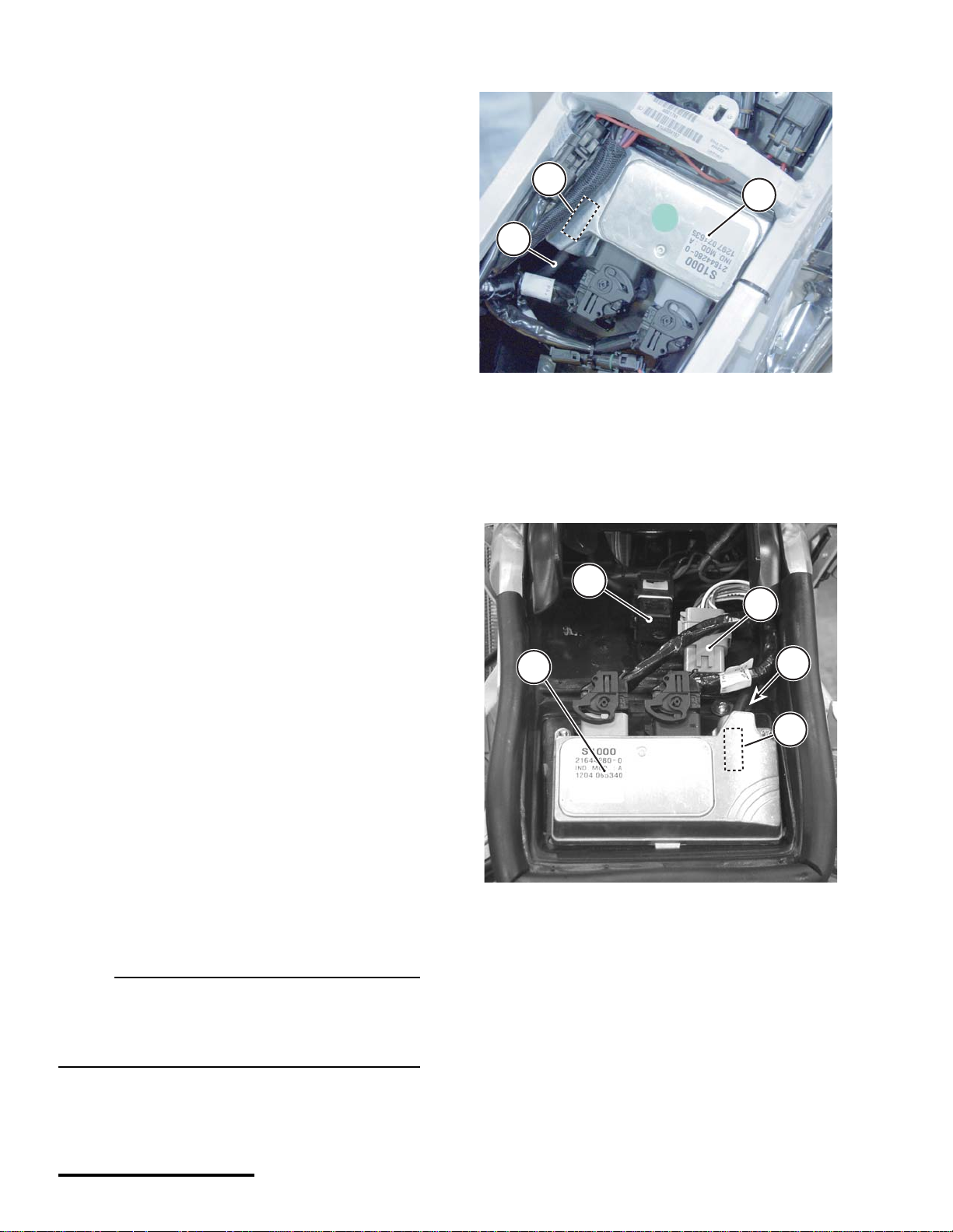
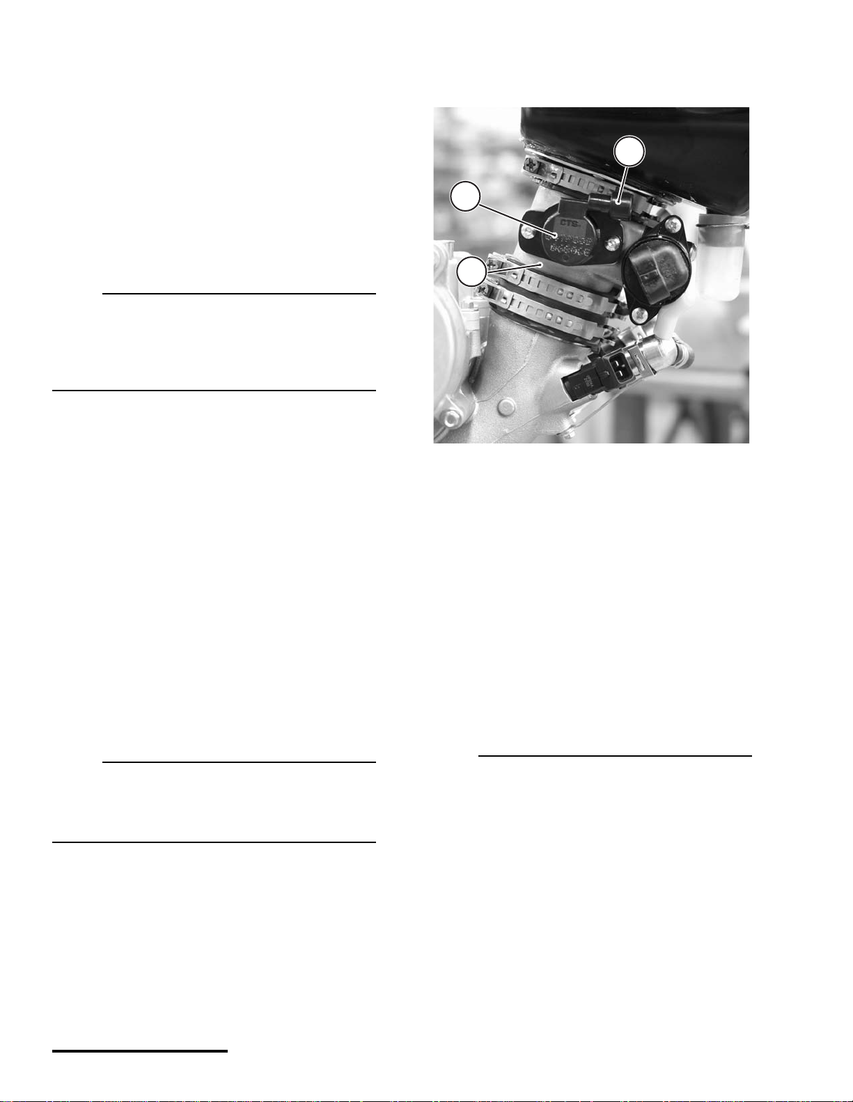
Motorcycle ECUs are located within the subframe.
A TV ECUs are located on the electronics tray under
the cowl.
1. ECU
2. Air pressure sensor hose (from airbox and fuel pressure
regulator)
3. Internal barometric (air) pressure sensor.
1. ECU
2. Air pressure sensor hose (from airbox)
3. Accessories connector
4. EMS power relay
1
2
3
2
3
3
4
1
7
8/14/02
7
ECU PROGRAMMING
The ECU is “programmed” with three types of infor-
mation. the operating code (also known as the “hex”
file, the engine calibr ation file (also kn own as t he
“map”), and the vehicle variables or “calibrations.”
Calibrations are stored in the map file but are specific
to the throttle body and injectors installed on the
vehicle.
Any programmed information can be changed.
using the Cannondale Diagnostic and Maintenance
Tool. Refer to "Cannon dale Diagnostic a nd Mainte-
nance Tool Version 2.0" starting on page 21.
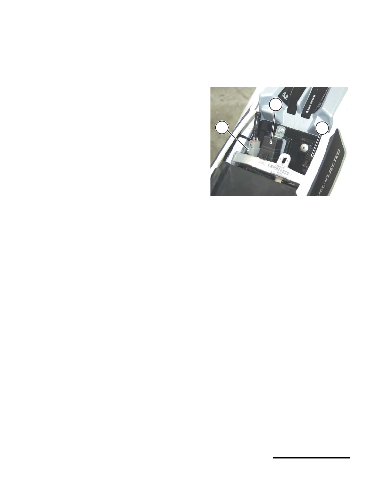
ECU diagnostic connectors
ATVs and motorcycles have a diagnos tic con-
nector to connect the software tool PC to the vehicle.
• On 2001 and 2002 Motorcycles, the diagnostic
connector is located near the ignition coil on the
top of the cylinder head.
• On 2003 motorcycles, the diagnos tic connector
is located near the main fuse under the seat.
• On 2001 - 2003 ATV the diagnostic connector is
located near the radiator shroud on the left side
of the ATV.
The tool is a combination of a specially developed
Windows- based software program and a data cable
used to connect your PC or pocket PC computer to
your vehicle. With the tool, you can read fault codes,
install engine calibration fil es, set v ehicle rpm , and
monitor engine operating parameters.
Reporting system faults
The ECU is capable of reporting system hardware
malfunctions during operation. It reports current
problems and does not store problem “faults” in
memory.
System faults are read from the ECU using the
Cannondale Diagnostic and Maintenance Tool, a
Windows-based PC pro gram enabling c ommuni-
cation between a PC and the vehicle ECU. The ECU
does not store intermittent fau lts; the fa ults repor ted
are occurring at the mom ent when the ECU Fault
Report windo w is s elect ed i n th e s oftwa re to ol. A
special commu nicati on ca ble is neede d to co nnect
the vehicle to a PC. Refer to "Cannondale Diag-
nostic and Maintenance Tool Version 2.0" starting on
page 21.
This manual provides step-by-step fault diagnostic
testing based on the ac tual fault repor ted by the
software tool. Refer to "Fault Troubleshooting"
starting on page 42.
1. Diagnostic connector
2. EMS power relay
3. Main fuse
3
1
2
© 2002 Cannondale Corporation - All Rights Reserved
8
Electrical_EFI Service Manual.fm
P1 and P2 Connectors
MC1000 ECUs have two main harness connector
sockets.
Remove both main harness connectors from the
ECU when performing pin point tests described in
this manual.
Also, if requir ed, be su re t o d iscon nect any oth er
devices; see the specific pin point tests.
• Connector P1 color is bl ack. It connects to the
black ECU socket.
• Connector P2 color is grey. It connects to the
grey ECU socket.
CAUTION:
Allow connector rotating latch to draw the
connector into the ECU socket (coupler) . Do not
press or force the connector; it should slide
into the socket easily.
Check for contamination and pin condition
before reconnecting.
Lubricate the connector seals with a high-
quality dielectric grease before reinstalling.
Use a commercially available pin gauge when
performing pin point tests. Ordinary tester
probes can spread pins resulting in loose
connections.
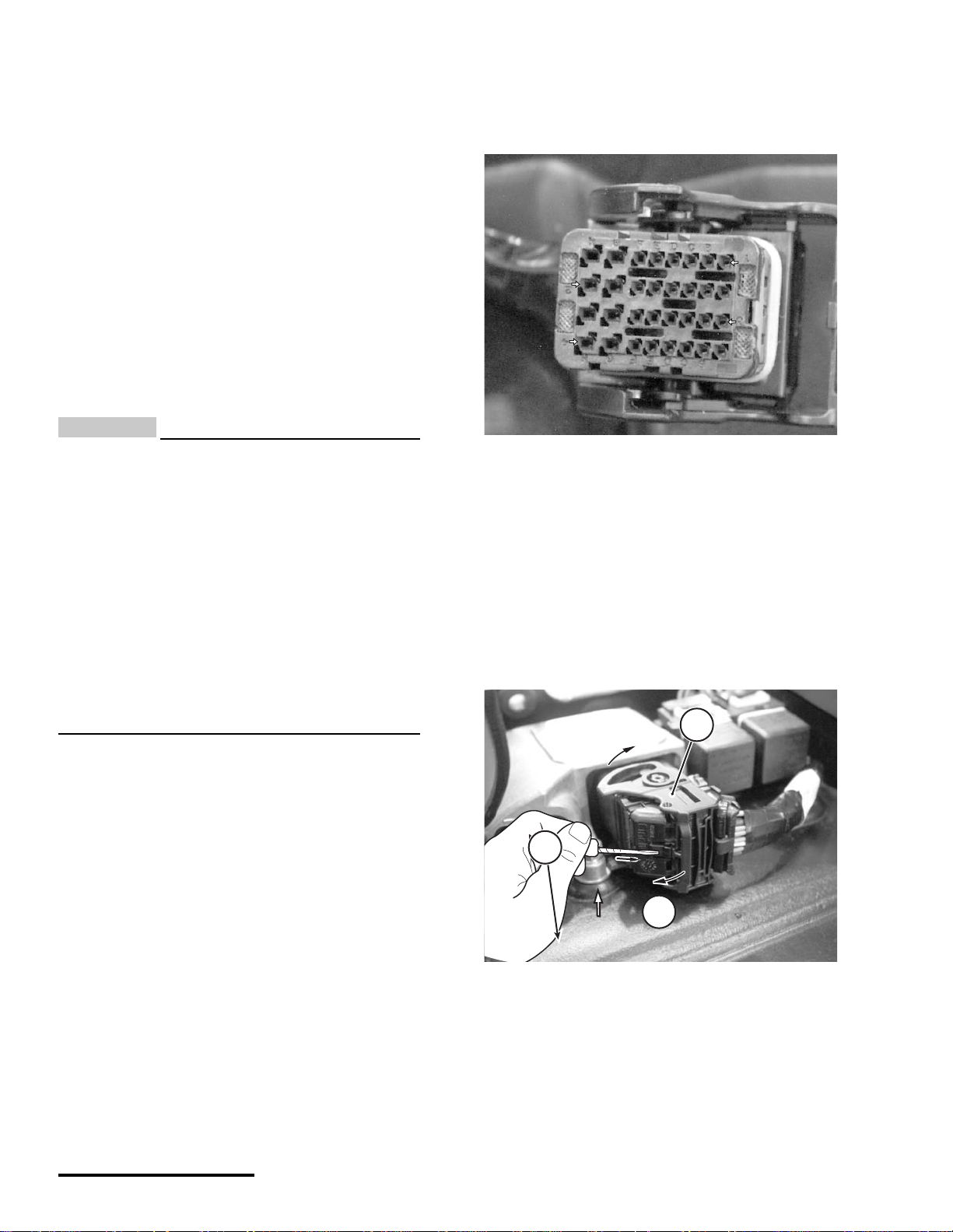
Pin identification (P1 or P2)
Use the following illustration for P1 and P2 pin iden-
tification.
Disconnecting the ECU
1. Disconnect the battery.
2. Press in the latch lo cking tab and rotate the latch
in direction (a) until it stops. Pull the connector
from the ECU socket.
Reconnecting the ECU
1. Make sure the battery is disconnected.
2. Make sure the main fuse is removed.
This photo shows how to identify individual pins in the ECU
harness connectors. Each row is identified by a number 1-4.
Each column is identified by a letter A - H.
1. Latch
2. Locking tab
H
H
B
G
F
E
D
A
C
H
B
G
F
E
D
A
C
1
2
3
4
a
1
1
9
8/14/02
9
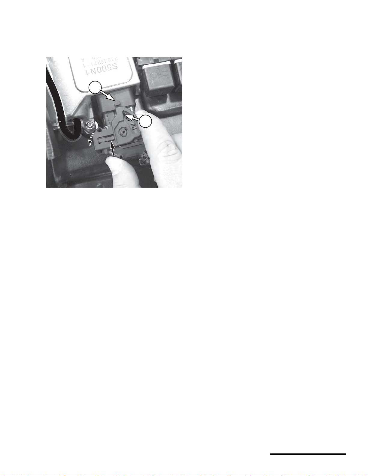
3. Align the latch groove and tab on the ECU socket.
Rotate the latch in direction (b) until the latch is
locked by the locking tab. The latch should oper-
ate freely with your fingers; do not force it.
SERVICING CONNECTORS AND
COUPLERS
Many electrical problems could be caused by faulty
electrical connectors or couplers. Check for the fol-
lowing conditions before beginning any diagnostics:
• wet terminals/pins
• dirty or corroded terminals/pins
• broken bent cable pins within multi-plug
couplers
• terminal pins backing out of the connector or
coupler
Connector - a single male lead that connects into a
single female lead.
Coupler - multi-pins and usually have some sort of
locking device (e.g., barb, hook, eye) which must be
released before the two halves can be separated.
Cleaning
1. Wipe the connector or coup ler with a clean, lint-
free rag and blow off any moisture using
compressed air.
2. Remove corrosion, rust, stains or other foreign
material by using contact cleaner on the termi-
nals.
3. Apply a water-displ acement chemi cal on connec -
tor seals.
4. Apply a light coat of dielectric grease onto the ter-
minals/pins, and properly connect the halves.
Disconnecting
• Release any locking device fir st.
• Do not pull the leads.
Connecting
• Inspect for bent terminals/pins, damaged c able
terminal/pin joints, water, dirt, or corrosion, and
secure wiring. If a terminal or pin is bent,
carefully straighten it with a thin-blade
screwdriver.
• Before joining or connecting, check for dirt or
corrosion
• Push male and female ends together squarely
to avoid incorrectly locating or bending the
terminal pins.
• Whenever a connector or coupler is
disconnected or checked, be sure to clean it
and apply some dielectric grease before
reconnecting.
• Make sure the two halves connect positi vely.
1. Latch
2. Tab
1
2
© 2002 Cannondale Corporation - All Rights Reserved
10
Electrical_EFI Service Manual.fm
BAROMETRIC PRESSURE SENSOR
The barometric pressur e sensor is housed within
the ECU. Air pressure within the airbox is transferred
to the ECU by a narrow hose. Air pressure infor-
mation is used to adjust the amount of injected fuel to
match the prevailing conditions. The sensor is not
user serviceable. If no external problems are found
with the hose or the hose routing end points, and a
barometric pressure sensor fault persists, the ECU
will have to be replaced.
NOTE :
When performing tests, start by checking the hose
routing from the ECU to the airbox. The routing
may be interconnected with other devices. Be sure
to check all vacuum/pressure routing hoses for
damage.
Dynamic Test - ECU Monitor
1. To test, determine the barometric pressure at
elevation in the operating area.
2. Read the reported sens or data with the Cannon-
dale Diagnostic and Maintenance Tool. This value
is reported at the “ Airbox Pressure (k Pa)” field in
the ECU Monitor window. Refer to "ECU Monitor"
starting on page 39.
3. Compare the known value with the one repor ted
by the software tool. If the comparison of the
actual value and the reported value results in a
wide dis pa ri t y, and no ot he r fa u lt s ar e present and
engine trouble remains, consider replacing the
ECU.
NOTE :
When comparing the actual barometric pressure
reading and the one reported through the
software, be sure to convert to equivalent units
(kPa).
THROTTLE POSITION SENSOR (TPS)
The throttle position sensor (TPS) is a rotary poten-
tiometer attached to the end of the throttle plate shaft
on the right side of the throttle body.
Fueling requirements are calculated by the ECU for
changing throttle positions.
The fully closed and fully open thr ottle positions
(interpreted by the minimum and maximum voltage
read through the sensor) are stored as numeric
values in the ECU.
N
OTE :
Anytime the throttle body is servic ed or the sensor
is removed or replaced, the min/ma x values must
be re-read into the ECU using the Update
Calibrations window of the tool.
Use the Cannondale Diagnostic and Maintenance
Tool.
Refer to "“Throttle Body Leakage” (also called
Throttle Body Offset) (Input range 0 - 100) The
equivalent amount, in percent, of throttle openi ng
1. TPS Sensor
2. Throttle Body
3. Harness connection point
2
1
3
11
8/14/02
11
required on a “perfect” throttle body to match the
air flow of the vehicle's throttle body at the closed
position. Typical values are from 0.0 to 1.0%"
starting on page 37.
The TPS sensor signal informs the ECU of not only
the relative position of the throttle plate, but also the
speed with which it is being opened or clos ed. The
engine load is determined by the TPS and engine
speed (rpm). The voltage output from the TP S
increases proportionately as the throttle is opened.
The sensor contains no user serviceable items.
Dynamic Test - ECU Monitor
1. Use the ECU Monitor windows of the Cannondale
Diagnostic and Maintenance Tool and read the
Throttle position (%) fi eld . T his field is the percent
the throttle plate is open as translated by the
ECU. With the throttle plate completely closed,
this value shoul d read between 2% to 3 %. When
the throttle is fully opened, a normal reading is
97% to 100%. When the idle adjustment is set,
this value should be approximately 3% higher
than the completely closed percent to achieve
rough idle. Fine tuning of the idle adjustment
screw which changes the% percent may be
required
If the Throttle Position (%) field values in the ECU
monitor window are erratic or inconsistent as
described above, the sensor can be tested further
by removing it and reading the resi stance values
with an Ohmmeter.
2. Attach a vacuum pump/pressure pump to the
hose end and monitor change. The reading
should increase when increased pressure is
applied. The reading should decrease when vac -
uum is applied.
N
OTE :
Be sure to convert the atmospheric pressure units
displayed in the ECU monitor window with units
displayed with the tools.
CAUTION:
Use of high pressure or vacuum when testing
may damage the sensor diaphragm.
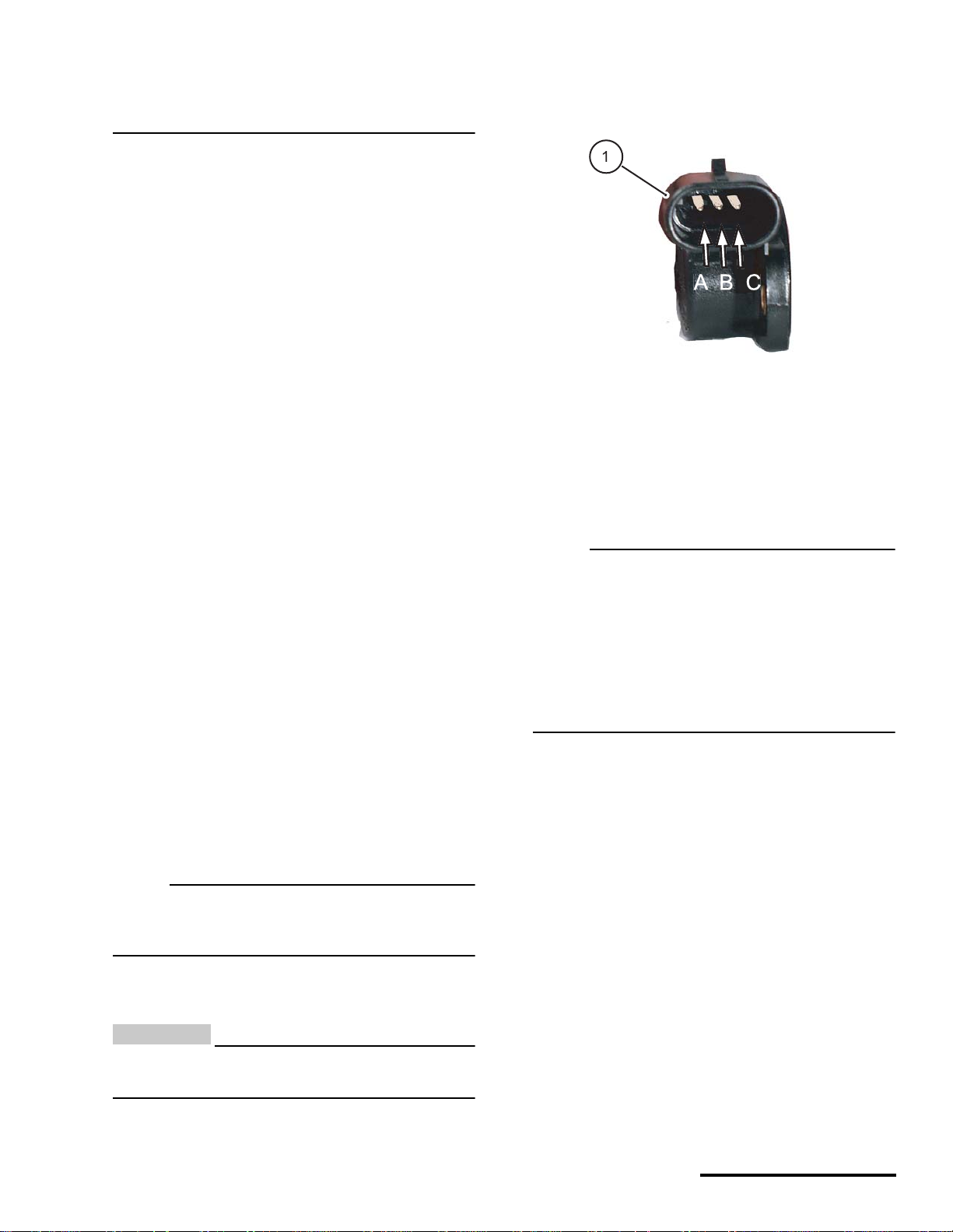
Static Test - Resistance
1. To test the sensor resistance, remove the sensor
harness connector, remove the mounting bolts,
and remove the sensor from the throttle body.
N
OTE :
Removing the sensor from the throttle pla te shaft
to measure the resistance is not required.
Removing it and inspecting the housing and shaft
socket for damage can be helpful. Remember that
is the sensor is removed, you will have to reset the
sensor min and max values using the software
tool. Refer to "Setting the throttle position sensor
minimum and maximum values" starting on
page 34.
2. Measure resistance across sensor terminals A
and B.
The resistance should be 1200 ± 240 Ohms.
3. Measure the resistance across sensor terminals
A and C.
- slowly rotate the sensor wheel clockwise and
observe variable resistance. Resistance should
increase smoothly from 0 to 1200 ± 240 Ohms.
1. TPS sensor (shown removed)
© 2002 Cannondale Corporation - All Rights Reserved
12
Electrical_EFI Service Manual.fm
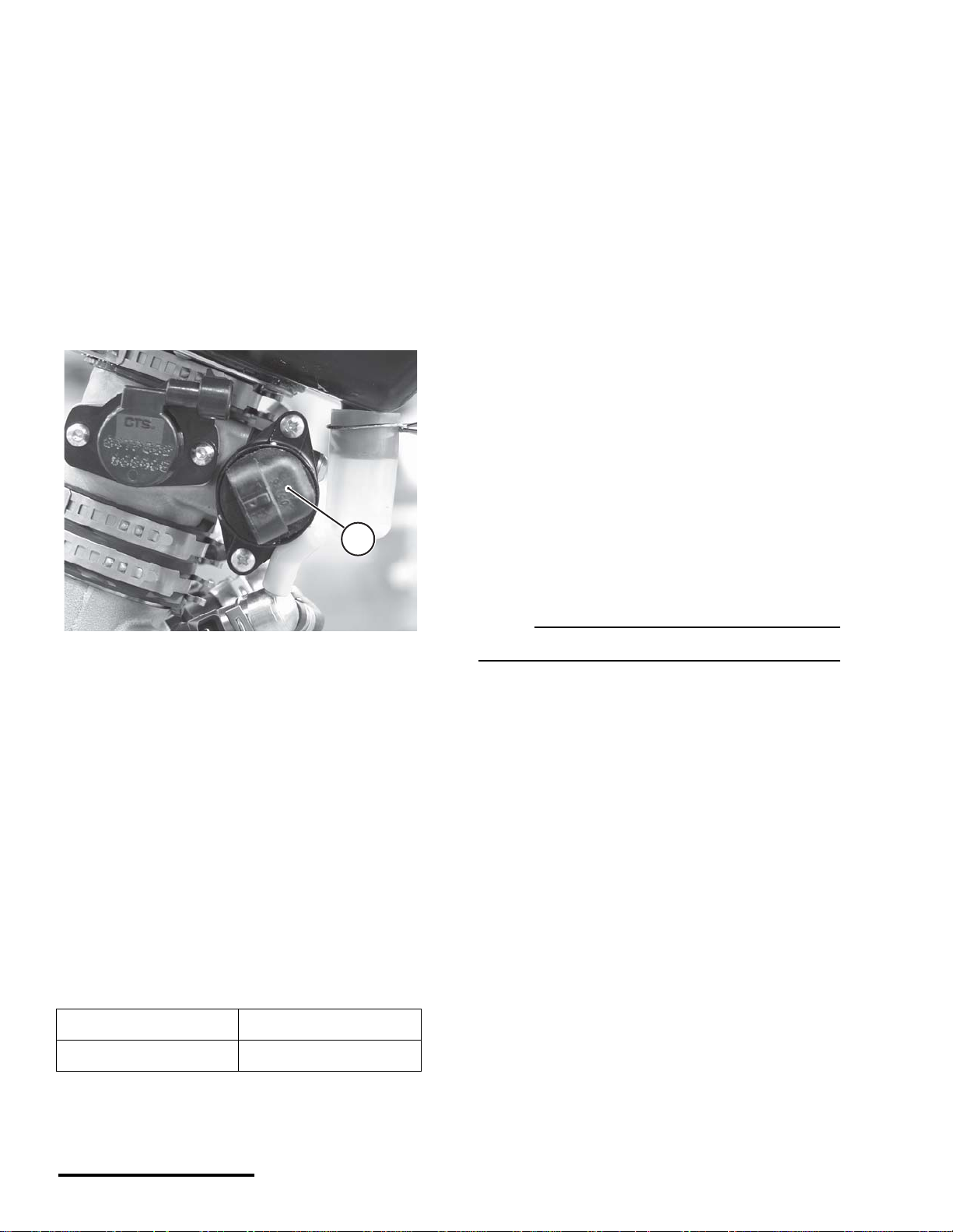
COOLANT TEMPERATURE SENSOR
The coolant temperature sensor is brown in color
and located on the front of the engine cylinder head.
It is an NTC thermistor.
The ECU measures the current flow through this
thermistor to groun d and u ses it to det ermin e the
engine coolant temperat ure. The ECU calculates
fueling to optimize engine performance at all tempe r-
atures. It also calculates hot and cold start fueling
requirements.
The sensor resistance decreases as the temper-
ature increases.
Dynamic Test - ECU Monitor
1. Starting with a completely cool engine, use the
ECU Monitor window of the Cannondale
Diagnostic and Maintenance Tool to read the
Engine Temperature (degC) field in the ECU
Monitor window. Refer to "Using the ECU
Monitor" starting on page 39.
2. Open the radiator cap and tes t the coolant tem-
perature with a thermometer.
3. Compare the values . If the two va lues do not cor -
respond closely, the sensor may be damaged. Go
to the next step.
4. Be sure to repl ace the radiator cap a nd start the
engine and allo w to reach operating temperature
(60°C). Observe the Engine Temperature (degC)
field in the ECU Monitor window. If the value does
not increase as the eng ine warms, go to the next
test.
Static Test - Resistance
1. Disconnect the sensor harness connector.
2. Use an Ohmmeter to measure the sensor resis-
tance between terminal s 1 an d 2 . Refe r to " Coo l-
ant Sensor Resistance Range" starting on
page 54. If measured resistance is inconsistent at
the tested temperature r eplace the sensor. If the
sensor is OK, the sensor harness wiring or the
ECU itself may be damaged. Take corrective
action.
AIR TEMPERATURE SENSOR
The intake air temperature sensor is attached to the
airbox with the tip mounted inside the airbox.
It is a NTC thermistor and green in color.
Resistance will drop as temperature rises.
The sensor tip is very sens itive to temp erature
change.
CAUTION:
The tip can be damaged easily; use extr a care
when installing or working inside the airbox.
The ECU uses the information from this sensor to
calculate the fuel necessary for a given air temper-
ature.
Dynamic Test - ECU Monitor
1. Use the ECU Monitor window of the Cannon dale
Diagnostic and Maintenance Tool to read the
Engine Temperature (degC) field in the ECU
Monitor window. Refer to "Using the ECU
Monitor" starting on page 39.
1. Coolant temperature sensor (ATV shown)
WARNIN
G
Never open the coolant system when the
engine is hot. Coolant is hot and under
high pressure. It can spray out forcefully
and burn or scald you severely.
1

13
8/14/02
13
2. Compare the value with a reading taken manually
in the vicinity of the ai r temperature tip. If the two
values do not corre sp ond clos el y, the sensor may
be damaged.
Static Test - Resistance
1. Remove the sensor from the ai rbox by pl acing an
open-end wrench o n the sen sor body and turni ng
it counter-clockwise until it can be removed.
2. Measure the sensor resistance between terminals
1 and 2. Refer to "Air Temperature Sensor Resis-
tance Range" starting on page 52.
If the measured res istance is inconsistent at the
tested temperature, replace the senso r.
If the measured resistance closely matches the
table values, the sensor is OK, the sensor har-
ness wiring or the ECU it self may be damaged.
Take corrective action.
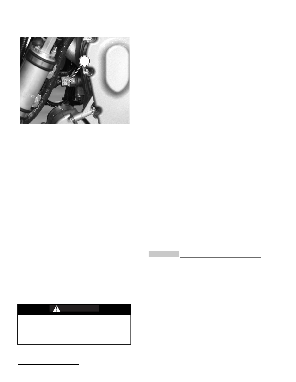
CRANKSHAFT POSITION SENSOR
SERVICE: Crankshaft position sensor gap
0.02 - 0.03 in (0.5 -1.0 mm)
The crankshaft position sensor is located in the
generator housing.
This senso r de te cts mo ve me nt of a toothed whee l
that is molded into the flywheel and attached to the
right side of the crankshaft. The wheel has a 36-tooth
pattern. The flywheel teet h are ev enly s paced wi th
the exception of one, tri ple -leng th to oth next to one,
triple-length gap. Everytime this tooth/gap passes the
sensor, the ECU interprets i t as b ott om de ad c en te r
(BDC). The EC U u s es t hi s i nf orm ati o n t o de ter m i ne
engine speed and crankshaft p osition i n relation to
the point where fuel is injected and ignition of the air/
fuel mixture occurs.
If the crankshaft position sensor malfunctions, the
engine will not start. If the sensor tip is contaminated
with metallic debris, oils and dirt, or incorrectly
gapped, the engine can run erratically.
If the flywheel is damaged, the sensor may be ok,
but may be reading bad information due to the
resulting change in the ind e xing betwe en th e c ra nk-
shaft and flywheel teeth. Refer to "Flywheel" starting
on page 58.
N
OTE :
Metallic debris or other contaminants on the
sensor tip will affect the sensor.
Inspection points
1. Ensure sensor connection to harness is secure.
2. Check sensor gap: 0.5mm-1. 0mm .
3. Check for magnetic debris on sensor tip.
4. Check for damaged flywheel teeth.
5. Check flywheel for run-out or play.
6. Check flywheel hub for cracking o r separati on.
Dynamic Test - ECU Monitor
1. Use the ECU monit or window to confirm change
in reported engine rpm.
With the engine off, there should be no reading
displayed at engine rpm field.
Crank the engine over and a reading should be
displayed. If no change is observed, the sensor or
harness circuit is faulty. Take corrective action.
The flywheel cover has been removed for this photo to show the
sensor tip.
1. Crankshaft position sensor
2. Sensor tip
3. Flywheel tooth
4. Gap
1
2
a
© 2002 Cannondale Corporation - All Rights Reserved
14
Electrical_EFI Service Manual.fm
Static Test - Resistance
1. Disconnect the sensor harness connector.
2. Use an Ohmmeter to mea sure the sensor resis-
tance between terminals 1 and 2.
SERVICE: Crankshaft position sensor
resistance range - 532 TO 588
Ohms
IDLE AIR CONTROL VALVE (IACV)
The Idle Air Control Valve (IACV) is an ECU c on-
trolled valve mounted on the throttle body.
As soon as the ECU is powered up, this valve
begins to move to the correct position (increasing or
decreasing the available air bypass volume needed
for cold start). The ECU co ntrols the valve arm
depending on engine temperature. The valve arm
moves in “steps” that extend or retract the valve arm
inside the bypass housing.
The arm travels.024mm per step.
Total travel = 0 to 255 steps
In a cold engi ne, th e val ve ope ns (ar m retr acts)
allowing more air to bypass the throttle plate. As the
engine warms up, th e valv e closes (a rm extend s)
until the bypass channel through the housing is com-
pletely shut at 60°C.
Here are some symptoms of a faulty IACV
• Hard starting - the valve arm could be stuck
shut. In this case, the extra air needed for cold
starting conditions is not available. Enough air
may be available to start a warm.
• Engine idles too fast - valve is s tuck open.
• Rough idle - if the valve arm is malfunctio ning
Dynamic Test 1 - ECU Monitor
1. Make sure the engine is completely cool.
2. Use the Cannondale Diagnostic and Maintenance
Tool to read current valve stepped position with
the cool engine.
Read the valve posi tion at IACV Stepper Positio n
field in the ECU Monit or wind ow. Refer to "Usin g
the ECU Monitor" starting on page 39.
N
OTE :
Make sure the monitor is in “continuous” m ode.
3. Start the engine and allow to it idle normally.
Observe the IACV Stepper Position and Engine
Temperature ( degC ) fie ld s. As the engi ne temper-
ature climbs, the IACV Stepper Position should
increase indi cating that the arm is extending and
the bypass channel in side the housing reducing.
At engine operatin g temperature (60°C) the arm
should be fully extended and the bypass closed.
4. If no change is observed, go to Dynamic Test 2.
Dynamic Test 2 - Confirm arm movement
1. Make sure the vehicle engine is compl etely cool
and press the engine stop button to ensure that
the ECU is powered down.
2. Remove the bypass housing from the throttle
body with the IACV valve attached to it.
1. Idle Air Control Valve (IACV)
IACV Stepped positions
Fully Open Fully Closed (at 60°C)
175 205
1

15
8/14/02
15
CAUTION:
Do not remove the valve from the housing whe n
performing this test.
3. Disconnect the engine coolant sensor.
4. Reconnect the idle air control valve to the har-
ness.
5. Press the engine s tart button quickly without tu rn -
ing over the engine. The valve should extend fully.
6. Reconnect the coolant sensor and observe move-
ment of the valve arm; the valve should retract
slightly.
If the valve does not mov e, replace it with a new
one.
Static Test - Resistance
1. Remove the valve moun ting screws and remove
the valve from the bypass housing.
2. Inspect the housing pintel seat and valve pintel
end for damage.
3. Measure resistance across sensor terminals (A)
to (D). The resistance shoul d be 53
± 10% Ohms.
4. Measure resistance across sensor terminals (C)
to (B). The resistance should be 53
± 10% Ohms.
IGNITION COIL
The ignition coil is a “pencil-type” coil located on top
of the spa rk plug within the cylinder head.
The ECU controls when the coil is switched on or
off. The coil is switched on to allow sufficient time for
the coil to charge to a level w here a spark can be
produced at the spark plug. The coil switches off at
ignition, which is timed for good engine performance.
Inspection Points
1. Check the coil body for damage (e.g., burning,
cracks, discoloration (excessive heat).
2. Check the coil termin al pins. Make sure they are
in good condition.
3. Check the co ndi tio n of the tip in sul ator. Make sure
it is not cracked, burned, melted, dried out.
4. Make sure the spring is installed with the larger
end facing the coil.
Dynamic Test - Spark Occurrence
1. Disconnect the ignition coil from the harness
connector.
2. Remove the retaining clip bolt and coil retainer.
3. Lift the ignition coil out of the cylinder head.
4. Reconnect the harness.
5. Insert a commercially available spark tester into
the end of the coil. Connect the ground lead of the
indicator to the cylinder head.
6. Turn the ignition switch o n and press the engine
start button. If spark is indicated, the coil is OK.
Static Test - Primary Resistance
1. Measure the res istance between t he coil termin al
pins.
EMS POWER RELAY
The EMS power relay supplies the ECU with power
when the vehicle start button is pr essed and will
remain locked when the engine is runn ing. The
relay will hold for up to 2 minutes without the engine
running or turning over, then it will drop power to
ECU.
WARNIN
G
An energized ignition coil generates a
high voltage spark capable o f jumping to a
ground point. The following procedure will
create a spark that can ignite any available
fuels. You can be seriously injured or killed
in a resulting fire or explosion.
Make sure the work area and vehicle are
free of any gasoline or flammable liquids
(flooded engine, fuel tank, fuel hoses, sol-
vents).
© 2002 Cannondale Corporation - All Rights Reserved
16
Electrical_EFI Service Manual.fm
On motorcycles, if this relay is damaged, the
engine can start but will shut down when the start
button is released.
On ATVs, if this relay is dam ag e d or r e mo ve d, th e
engine will run, but damage to a harness diode will
result. When the diode fails, the engine will not run.
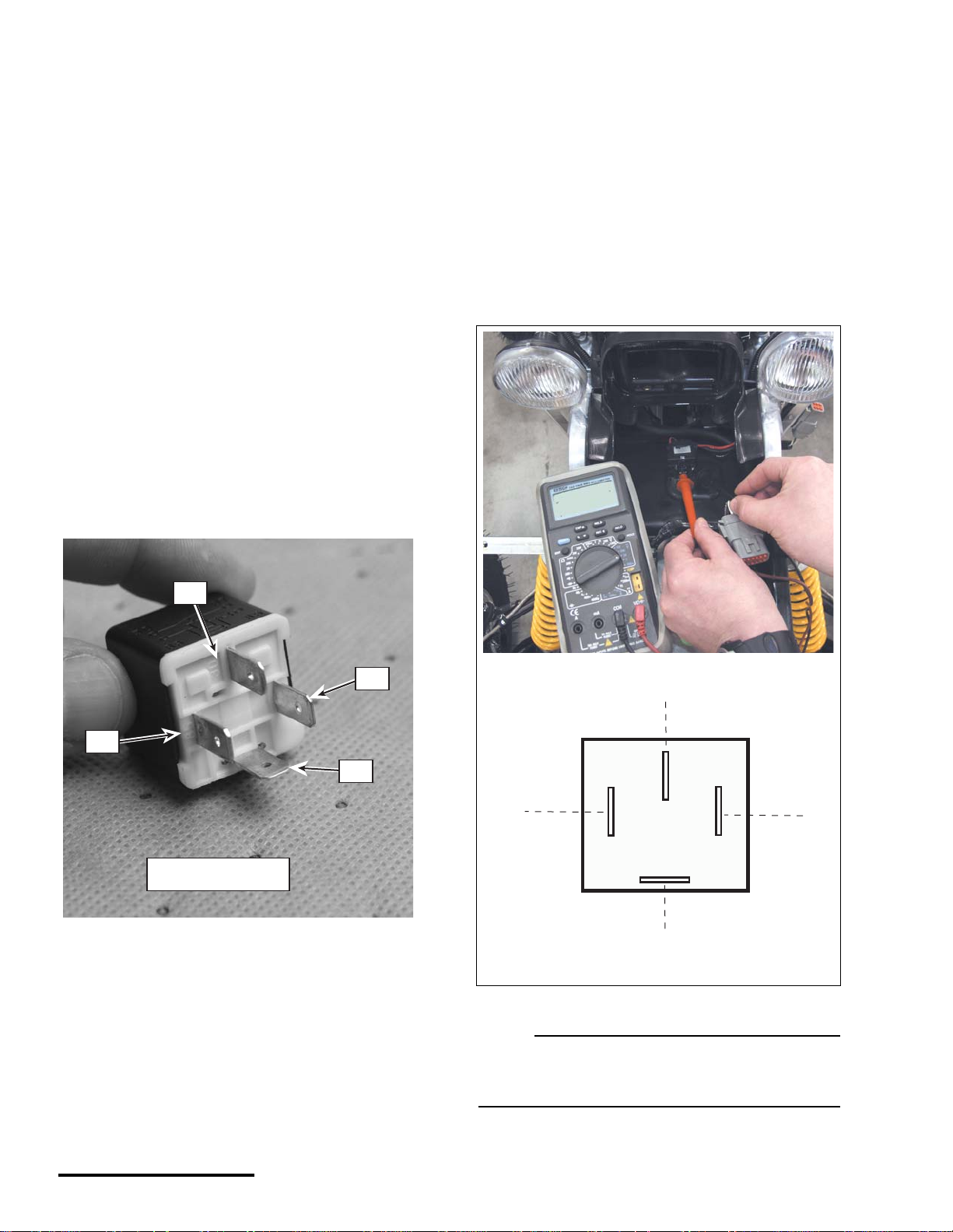
Dynamic Test
1. Remove the relay from its harness socket.
2. Using an ohmmeter, connect the positive probe
(+) onto terminal number 86 and the negative
(-) probe onto terminal number 85. Check the
resistance. The resistance should be 1500
± 10%
Ohms.
Reverse the meter le ads. If th e readin g is OL (n o
continuity), go to the next step.
If the relay is out of specification, replace the relay
with a new one. If the measured resistance is OK,
go to the next step.
3. Using an Ohmmeter, connect the positive
probe (+) onto terminal number 30 and the
negative (-) probe onto terminal number 87.
Check the for continuity. There should be no
continuity. If continuity is observed, the relay
is damaged; replace it. If no continuity is
observed, go to the next step.
4. Connect 12 V (+) battery voltage to the
number 86 terminal and ground terminal
number 85. There should be continuity
between terminals 30 and 87. If the re is not,
the relay is damaged; replace it.
5. Use a voltmeter to verify tha t there is vo ltage
present at the wiring harness socket
corresponding to relay terminal 87. Do not
start the engine. If there is no voltage present,
check the main fuse. Use the vehicle wiring
diagram to check the c ircuit. Take correctiv e
action.
There are no markings on the socket itself;
use the illustration below for identification.
N
OTE :
Wiring diagrams are available on our web site.
http://www.cannondale.com/motorsports/tech/
servman.html
"30"
"85"
"87"
"86"
RELAY - P/N 5000411
30
86
85
87
12.5 VDC
SOCKET
17
8/14/02
17
N
OTE :
When the ignition switch is turned “ON,” the
installed relay will make an audible “ clic k.”
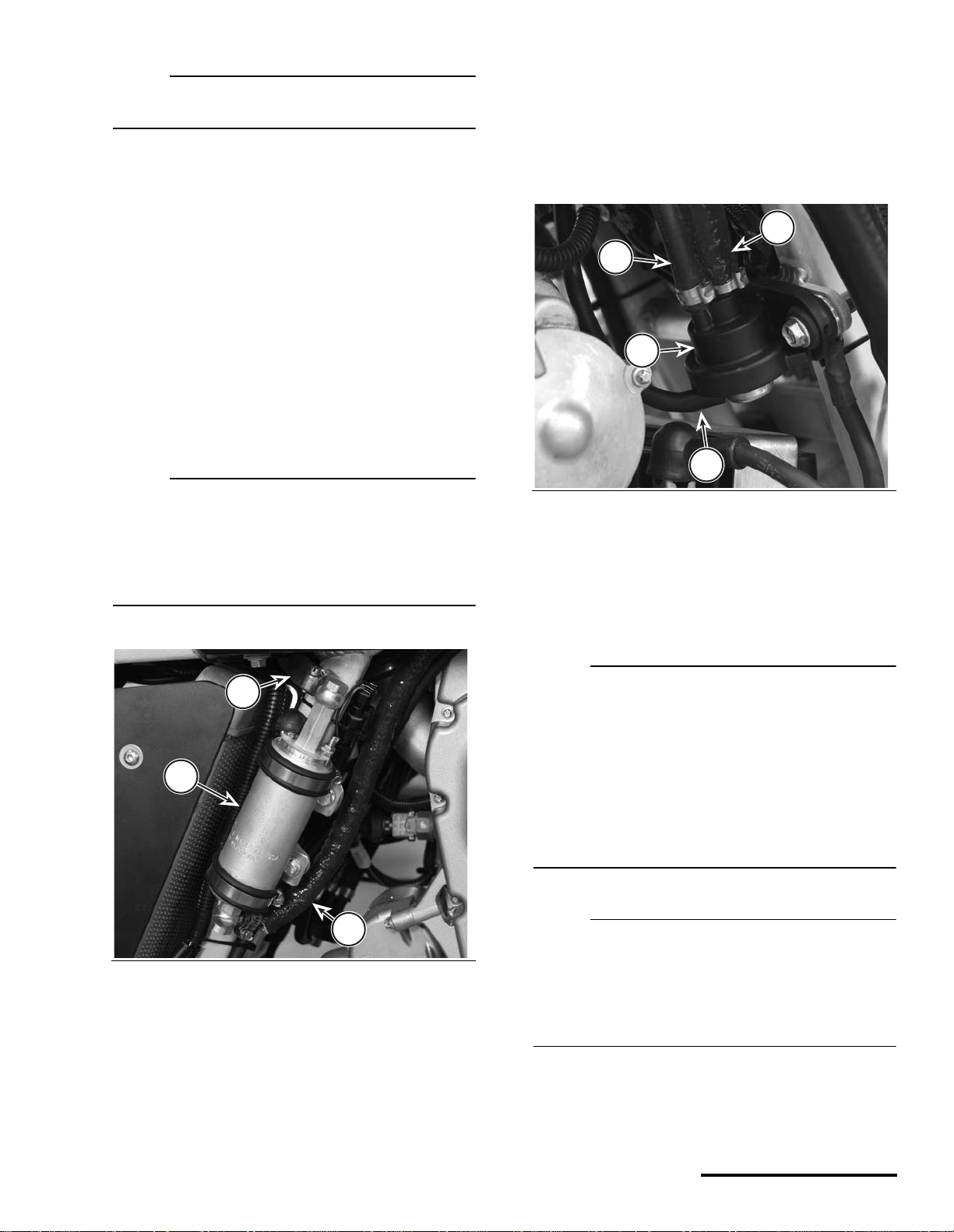
FUEL PUMP AND FUEL PRESSURE
REGULATOR
The fuel pump and regulator maintain fuel supply
and pressure to the injectors. When the engine man-
agement system is first “powered-up,” this pump acti-
vates for 3 seconds to pressure the fuel system then
turns off again until the engine starts. When the
engine starts, it resumes pumping, providing pres-
surized fuel to the injectors. The regulator returns
fuel to the fuel tank.
N
OTE :
The positive (+) pump terminal is always “hot” -
even with the ignition switch OFF. Thi s terminal is
connected directly to the positive battery voltage
through the main fuse. The pump is acti vated by
ECU switching the negative circuit to ground.
Consult the vehicle wiring diagram for more detail.
The fuel pressure regulator maintains the correct
fuel pressure in the fu el rai l ( ho ses an d i nj ect or s ). It
returns fuel to the tank after fuel passes the fuel
injectors. The regulator is connected to the airbox via
a small hose. On ATVs the fuel pressure regulator is
mounted on the main frame on the right side of the
vehicle (front).
Dynamic Test - Pump and Regulator
N
OTE :
If you suspect a problem with the fuel pump, first
check to see if it runs at all. Do the following :
Turn the ignition switch “ON” and listen to the
pump, it should make a “whirring” sound for a few
seconds to pressurize the syste m - then the pump
will turn off.
Start the engine and allow the vehicl e to idle. You
should hear a constant whirring” sound - although
it is more difficult to hear.
N
OTE :
The pump will turn anytime the start button is
pressed on motorcycles, however, the pump
circuit is different is different on ATVs. If the ECU
has not powered down, the pum p will not turn on
unless the clutch lever is pulled in and the start
button is then pressed momentarily.
1. If the fuel pump does not turn on, check the
following:
Pump wiring terminals. Make sure they are clean
1. Fuel pump
2. Fuel inlet (from tank)
3. Fuel outlet (to injectors)
2
3
1
Components have been removed for this photo.
1. Fuel pressure regulator housing
2. Fuel hose (from injectors)
3. Fuel hose (return to tank)
4. Air pressure hose (from airbox)
4
1
2
3
© 2002 Cannondale Corporation - All Rights Reserved
18
Electrical_EFI Service Manual.fm
and the wiring is in good condition. Make sure the
boots are in place.
Check for voltage at the pump when the start
button is pressed. Check for any open or short
circuit conditio ns in the fu el pump ci rcuit. Consul t
the vehicle wiring diagram. Take corrective action
if necessary.
Quick connect fuel fittings - Make sure the O-rings
are in good condition. Damaged O-rings can
result in pressure loss or the introduction of air
into the fuel lines reducing developed fuel
pressure. The fittings have an internal and
external O-ring. Exte rnal O-rings can be chec ked
visually. Fuel flow can be restricted or s top is the
internal O-rings are swollen or damaged.
2. Replace the fuel filter to assure adequate fuel flow
to the pump.
CAUTION:
Do not perform this test with unfiltered fuel;
severe damage can occur to the pump or fuel
injectors.
3. Fill fuel tank with the specified fuel as required.
4. Hold a clean rag around the regulator inlet and
loosen the hose clamp to reli ev e any res id ual fuel
system pressure.
5. Install a T-fitting and fuel pressure gauge between
the regulator inlet and hose coming from the
injectors. Make sure the return line attached to
the regulator outlet is con nected to the fuel tank-
tank.
6. Start the engine and read the generated fuel pres-
sure.
If the fuel pressure reading is OK, the pump and
regulator are OK.
If the fuel pressure reading is low, quickly discon-
nect and reconnect the fuel ta nk return l ine, if the
fuel pressure reading increases when the return
line is disconnected, the regulator is faulty replace
it.
If the fuel pressure does not increase, replace the
pump and regulator.
SERVICE: Fuel pressure
3.0
±
.25 bar
Dynamic Test - Voltage test
1. First, use a multi meter to check for battery
voltage to the pump at the (+) fuel pump terminal.
2. Use an Ohmmeter. Connect the p ositive lead to
main harness connector CN16 pin B. Connect the
negative lead to ground. Have an assistant turn
the ignition switch “ON”. Press the engine start
button and release it.
If there is continu ity, the pum p harness circuit is
OK.
If there is no continuity, disconnect the ECU and
check for continuity between CN16 pin B and
ECU connector pin P1 H1. There shoul d be cont i-
nuity. Take corrective action and repeat step 2.
If no continuity is present between CN16 pin B
and P1 H1 after the circuit is corrected, replace
the ECU (It is not switching the pump circuit to
ground).
WARNIN
G
Gasoline is extremely flammable and is
explosive. Handle with extreme care!
When inserting a pressure gauge into the
fuel system, make sure all hose connec-
tion are secure. Make sure the fuel tank
outlet and inlet lines are connected prop-
erly to the tank.
19
8/14/02
19
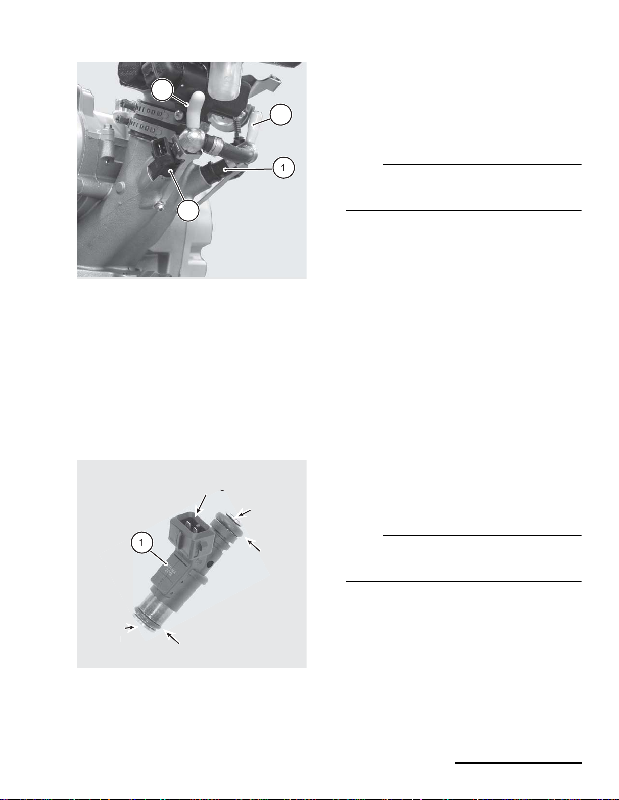
FUEL INJECTORS
ATVs and motorcycles utilize a pair of fuel injectors
that operate (inject) simultaneously.
Pressurized fuel flows into the injectors from the
fuel pump. The fuel is delivered into the intake port
when the EC U sends voltage t o the i nj ector internal
solenoid. When th e soleno id actu ates, th e pres-
surized fuel sprays, through the nozzle.
The fuel injectors are positioned as close as pos-
sible to the bac k of the intak e valves. Th e spray
pattern is fixed. The length of time duration that the
injectors stay open is calcul ated b y th e ECU using
the calibration file and data received by the various
sensors.
Dynamic Test - Function
N
OTE :
The following procedure is based on the
assumption that there is adequate fuel supply and
pressure is available in the fuel rail .
1. Check the injector wiring harness connectors.
Make sure they are secure.
2. Check that the batter y is fully charged. The sen-
sor and actuators of the sys tem depend on accu -
rate voltage readings to meter the fuel.
3. Check the air filter element. If it is dirty or blocked,
this will severely impede air flow and fuel econ-
omy.
4. Check the airbox and throttle body assemblies for
possible air leak s that wo uld resul t in a le aning of
the fuel mixture.
5. Use an automotive stethoscope to determine if
each injector is working properly. You should hear
a steady clicking sound that rises and falls with
the engine speed.
If you hear nothing, use a commercia lly available
noid light to test for voltage present at the harness
connector.
N
OTE :
If you do not have a stethoscope, y ou can use a
screwdriver against the injecto r and liste n through
the handle.
Static Test - Resistance
1. Disconnect the in jector, and test the resistan ce of
each injector across the terminals. If the
resistance value is out of specification, replace
the injectors as a pair.
SERVICE: Fuel, fuel injector, resistance
11.75 to 12.75 Ohms
2. Install the injector test light (one at a time) into
Engine shown removed for clarity.
1. Left fuel injector
2. Right fuel injector
3. Fuel inlet (from fuel pump outlet)
4. Fuel outlet (to pressure regulator)
1. Fuel injector (left or right)
TOP
FUEL ENTRY
)
O
-RIN
G
N
O
ZZL
E
FUEL EXIT
)
CONNECT
O
-RIN
G
Loading...