

Page 1
127534
Page 2
127534.PDF
CONTENTS
Safety Information ..................................... 2
Intended Use ............................................................... 2
Battery & Charger ....................................................... 3
Rack & Kickstand ......................................................... 3
Parts of the E-Series Bike .............................. 4
Frame ......................................................................... 4
BOSCH Drive Unit ........................................................ 5
BOSCH Handlebar
Mounted Interface (HMI) ............................................6
BOSCH Speed Sensor ................................................... 6
BOSCH Battery Pack .................................................... 8
BOSCH Charger ............................................................ 9
Operation Instructions ............................... 10
Turning the System ON/O .......................................10
Lighting ....................................................................10
Trip Information ........................................................ 10
Selecting Assistance Mode/Support Level ................. 11
Factors Aect Assistance Range ................................12
Error Codes ................................................................ 12
Keys ..........................................................................13
Headshok Suspension Fork ......................... 14
Maintenance ............................................ 16
Cleaning.................................................................... 17
Tightening Torques ................................................... 17
Geometry .................................................. 18
About This Supplement
Cannondale Owner’s Manual Supplements provide
important model specic safety, maintenance, and technical
information. They are not replacements for your Cannondale
Bicycle Owner’s Manual.
This supplement may be one of several for your bike. Be sure
to obtain and read all of them.
If you need a manual or supplement, or have a question
about your bike, please contact your Cannondale Dealer
immediately, or call us at one of the telephone numbers listed
on the back cover of this manual.
You can download Adobe Acrobat PDF versions of any
Cannondale Owner’s Manuals or Supplements from our
website: http://www.cannondale.com/.
Online E-Series Product Support
You may download a copy of this supplement and other
manuals and instructions available for your bike at :
http://www.cannondale.com/support-ebike
Your Cannondale Dealer
To make sure your bike is serviced and maintained correctly,
and that you protect applicable warranties, please coordinate
all service and maintenance through your authorized
Cannondale Dealer.
NOTICE
Unauthorized service, maintenance, or repair parts can
result in serious damage and void your warranty.
Specications ............................................ 19
Replacement Parts .................................... 20
This bike complies with EN 15194 Electrically Power Assisted Cycles (EPAC).
02/11
1
Page 3
SAFETY INFORMATION
Intended Use
ASTM F2043
ASTM CONDITION 2,
General Purpose Riding.
For o-road
riding and
jumps less than
12” (30cm)
Your E-Series bike has an electric pedal assist drive system.
It is not a moped or motorcycle. In EU contries, it is known
legally as an “EPAC” cycle or Electrically Powered Assisted Cycle.
The drive assist system consists of a drive unit, a battery, a
computer control, and various electronic components (harness
wires, sensors, and switches). Your E-Series bike does share
components common with pedal-only bikes. See Figure 1.
It is important to know that when the assist system is turned
ON, the drive unit enages to provide power only while you
are pedaling. The amount of power provided by the drive unit
depends on your pedaling force and the assistance mode/level
you set with the handlebar control unit. At anytime, if you
stop pedaling, the drive assist will dis-engage. In all modes/
levels, the drive assist system power reduces progressively and
cuts o as the bike reaches a speed of 25 km/h, (15.5 mph) , or
sooner if you stop pedaling. The drive assist re-enages when
speed drops below 25 km/h, (15.5 mph) as long as the pedals
are turning.
Whenever the drive assist system is turned OFF, You can pedal
the bike normally. The drive system will not engage.
WARNING
INTENDED USE: This bicycle is intended to be used
as a commuter bicycle. This bike complies with the
requirements of European Standard EN 15194, Electrically
Power Assisted Cycles. The drive assist system is limited
to a maximum continuous power rating of 0,25 kW (250
W) and a maximum speed of 25Km/h, (15.5 mph).
NOT INTENDED: You must not ride this bike in
automobile trac lanes. This vehicle must only be
operated on paved surfaces that are legally open to
commuter pedal bicycles. This bike is not for mountain
biking use, jumping, or racing.
YOU MUST FOLLOW ALL LOCAL LAWS: It is your
responsibility to identify and follow all local laws and
regulations (including tting your bike with additional
equipment) necessary to comply with local laws. Ask your
Cannondale Dealer for more information about operating
an electrically assited pedal bicycle in your area.
DO NOT MODIFY THIS BICYCLE/FORK IN ANY WAY FOR
ANY REASON. Doing so can result in severe damage,
faulty or dangerous operating conditions, or violation of
local laws.
IMPORTANCE OF PRACTICE & RIDER TRAINING -
Before you ride this bike, practice riding in a safe area
free from hazards. Take time to learn to bike’s controls
and performance. Practice the controls and gain the
experience necessary to avoid the many hazards you will
encounter while riding.
UNDERSTAND YOUR BIKE AND ITS INTENDED USE.
USING YOUR BIKE THE WRONG WAY IS DANGEROUS.
Please read your Cannondale Bicycle Owner’s
Manual for more information about Intended Use
and Conditions 1-5
YOU CAN BE YOU SERIOUSLY INJURED, PARALYZED OR
KILLED IF YOU IGNORE THESE WARNINGS.
.
2
Page 4
127534.PDF
Battery & Charger
WARNING
BOSCH INSTRUCTIONS - In addition to this supplement,
you must read and follow the BOSCH battery and charger.
instructions. Go to : http://www.cannondale.com/
support-ebike
REPLACEMENT - Only use the battery pack and charger
indicated in the Specications section of this supplement.
Do not use other batteries or chargers. Do not use the
charger to charge other batteries.
PREVENT DAMAGE - Do not drop the battery or charger.
Do not open or modify the battery or charger. No user
servicable parts inside.
Keep the battery out of intense sunlight. Keep away from
heat. Heat will damage the battery.
Keep battery away from paper clips, coins, keys, nails,
screws or other small metal items, to prevent shorting
exposed battery contacts. Shorting battery contacts can
cause severe burns, re, or explosion.
ACCIDENTAL ACTIVIATION - Always remove battery from
bike rack before working on the bicycle or if you transport
the bike by car or plane. Accidentalactivation of the
bicycle drive system can result in serious injury.
STORAGE & TRANSPORTATION - When the battery is
not in use in the bicycle, its transportation is subject
to hazardous materials regulation. Special packaging
and labeling requirements may exist. Contact local
authorities for specic requirements. Never transport
a damaged battery. Insulate battery contacts before
packaging. Package battery inside shipping container to
prevent damage.
CHARGING - Remove battery from bike before charging.
Bring indoors and allow to reach room temperature
before charging. Make sure charger and A/C outlet are the
same voltage.
Locate both charger and battery indoors, in a clean, dry
area with good ventilation to charge. Make sure the
area is free from combustibles to avoid re from sparks
or overheating. Keep charger ventilation openings
unobstructed. Do not cover the charger.
Disconnect the battery from the charger unit when fully
charged. Do not leave a fully charged battery connected
to the charger. Unplug the charger from the wall outlet
when not in use.
DISPOSAL- Battery pack/charger contain regulated
materials and must be disposed/discarded in accordance
with national and/or local laws. Do not discard the battery/
charger into re, water or ordinary household waste/
garbage. Take to a waste facility/recycler.
+
Failure to observe these warnings can result
in electrical res, explosion, or severe burns or
electrocution.
YOU CAN BE YOU SERIOUSLY INJURED, PARALYZED OR
KILLED IF YOU IGNORE THESE WARNINGS.
Rear Rack & Kickstand
WARNING
Do not sit on the bicycle with the kickstand down.
Kickstand is not designed to support the weight of a
person. Make sure kickstand is up before riding.
Do not overload the rear rack. Make sure the cargo is
secured properly.
YOU CAN BE YOU SERIOUSLY INJURED, PARALYZED OR
KILLED IF YOU IGNORE THESE WARNINGS.
3
Page 5
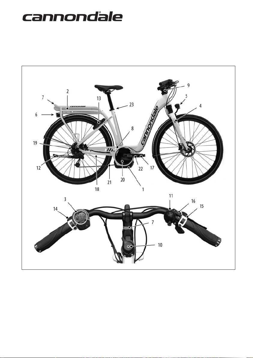
PARTS OF THE ESERIES BIKE
Frame
Figure 1.
1. BOSCH Drive Unit
2. BOSCH Battery
3. BOSCH HMI Unit
4. Headshok Fork
5. Headlight
6. Taillight
7. Rack
8. Chainguard
4
9. Headshok Stem
10. Lockout Lever
11. Bell
12. Kickstand
13. Rear Wheel Lock
14. Front Brake Lever
15. Rear Brake Lever
16. Rear Shift Control
17. Pedal
18. BOSCH Speed Sensor
19. Rear Cassette
20. Front Chainring
21. Drive chain
22. Crankarm (drive side)
23. Seat Binder
Page 6
127534.PDF
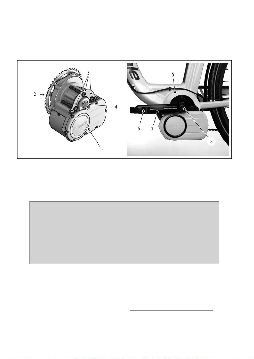
BOSCH Drive Unit
See Figure 2. The BOSCH drive unit (1) is mounted to the frame bottom bracket node (5). Control cables from the HMI unit,
battery, and speed sensor are routed to the unit inside the frame.
Figure 2.
1. BOSCH Drive Unit (removed)
2. Front Chainring
3. Frame Mounting Bolts
4. ISIS Axle end (non-drive side)
5. Frame BB Node
6. Pedal
7. ISIS Crankarm (drive side)
8. ISIS Crankarm Bolt
NOTICE
Drive unit is maintenance-free and must only be serviced at an authorized service center. This will ensure the quality
and safety of the driving unit. Never attempt to open, remove it from the frame, or work on it yourself.
Other components of the eBike drive (e.g. drive chain, front chain ring, rear cassette, rear derailleur, crankarm)
must be serviced by your Cannondale Dealer. Replacement parts must be identical to the original Cannondale
specication for the bike. See Specications. Failure to replace components with original specication can result
in serious overload or other damage to the drive unit.
Unauthorized opening or service of the drive unit will void the warranty.
Please note: The drive unit utilizes an ISIS standard drive axle. While the ISIS crankarms can be removed a reinstalled following
crankarm manufacturer’s instructions, the ISIS axle itself can not be removed from the BOSCH drive unit. It must be serviced at an
authorized service center.
See also BOSCH Instructions 0 275 007 X00 http://www.cannondale.com/support-ebike
5
Page 7
BOSCH Handlebar Mounted Interface (HMI)
See Figure 4. The handlebar mounted interface (HMI) is a cycling computer (1) that enables you to both control the bicycle’s
drive assistance functions as well as turn lighting on and o, and display speed, distance, and display trip several functions. The
buttons and display functions/features of the (HMI) are described on the next several pages.
The HMI unit attaches to the handlebar mounting base (2). The base unit should be positioned on the handlebar for convenient
use without interference with other bicycle controls. The handlebar position can be changed, however, to avoid damage, this is
somethingyour Cannondale Dealer should do for you.
To remove the computer:
When the bicycle is not in use, remove the computer unit (1) from the base (2) to prevent theft. To remove the unit, carefully
twist the computer unit counter-clockwise and detach.
To re-install the computer:
Align and mate the tabs on the back of the computer with the corresponding slots in the base unit. Rotate the computer unit
clockwise until it clicks into place on the base unit.
NOTICE
The drive system will not function without the computer unit attached to the base properly. If the computer
disconnects from the base during operation, the drive system will shut o. If this happens you will have to
stop the bike, turn the system o , re-attach the computer to the base, and then turn the system back on to
resume.
Remove the computer when not operating the bike to prevent theft or unauthorized use.
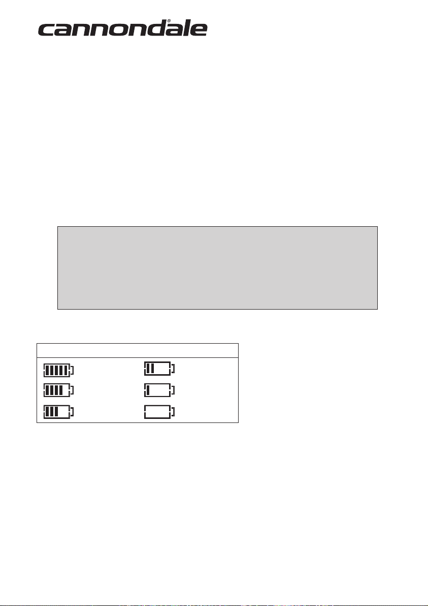
The HMI displays the battery charge level (13) continuously as long as the computer is turned ON.
Displayed/ Battery Level (for reference only)
100 - 80% 39-20%
79 - 60% 20 - 5%
59 - 40% 5 - 0%
Figure 3.
BOSCH Speed Sensor
See Figure 4. The BOSCH speed sensor (14) is mounted on the rear chainstay (15). This device must be attached and
functioning properly in order for system to work. If it is damaged, set-up incorrectly, or the magnet (16) is not present on the
wheel spoke (17) the drive system and speedometer will not function.
To adjust it’s position, loosen the screw (18 ) on the magnet. Slide the magnet along the spoke to adjust the distance between
the magnet and speed sensor. Spin the wheel to check the speed registers on the HMI to ensure the distance is set correctly.
Ensure the magnet is facing the speed sensor or it will not function. The maximum working distance (a) is 17mm.
6
Page 8

127534.PDF
Figure 4.
1. Computer
2. Handlebar Base Mount
3. Information Reset Select Button
4. Assistance Modes Button (Eco,
Tour, Spor t, Speed)
5. Lighting On/OFF Button
6. Support Level Decrease Button
7. Support Level Increase Button
See also BOSCH Instructions 0 275 007 X00 http://www.cannondale.com/support-ebike
8. Speedometer Readout
9. Light Indicator
10. Current Support Level
11. Current Assist Mode, Error Code
12. Multi-Function Display
13. Battery Charge Level
14. Bosch Speed Sensor
15. Chainstay
16. Magnet
17. Spoke
18. Set Screw
a. Sensor Gap
7
Page 9

BOSCH Battery Pack
4
See Figure 5. The battery pack is located in the rear bike rack. It is locked in the rack with the same key that operates the rear
wheel lock.
3
9
Figure 5.
1. System ON/OFF button
2. Battery Charge Level LEDs
3. Key
4. Lock
5. BOSCH Battery
6. Battery Handle
7
8
1
100%
5
BOSCH - 1 270 020 500
2
6
7. Rack
8. Rail
9. Base Connector
To remove the battery from the bike rack:
Insert the key (3) into lock (4) and turn key completely clockwise (toward rear of bike) to unlock the battery. Remove key from
lock. Hold the back of the battery (5) by the handle (6) and pull battery out of the rack (7).
To reinstall the battery in the bike rack:
Insert the key into the lock and and turn the key completely clockwise, making sure it is unlocked. Align the battery with the rail
(8) and base connector (9) in the rack. Slide the battery into the rack until it clicks into the base connector. Turn the key counterclockwise (toward the front) until the battery is locked. Remove the key from the lock.
See also BOSCH Instructions 0 275 007 40X http://www.cannondale.com/support-ebike
8
Page 10

BOSCH Charger
To ensure maximum operating range, make sure battery charge level is 100% before each ride.
127534.PDF
FAST - 2,5 Hr.
SLOW - 8 Hr.
SCHNELL 2,5 Stunden
LANGSAM 8 Stunden
LENT : 8 heures
RAPIDE : 2,5 heures
LENTO- 8 ore
VELOCE 2.5 ore
Figure 6.
1. BOSCH Charger
2. Wall cord
3. AC Voltage Switch
BOSCH - 0 275 007 900
4. Power LED
5. Charger Connector
6. Battery Jack
NOTE: Battery temperature is
internally monitored to permit
charging only when battery
ambient temperature ranges
between 0 ° C and 40° C. This
ensures high battery life is achieved.
7. Charge FAST, SLOW Button
8. Charger ventilation.
To charge the battery:
See Figure 6. Remove the battery from the bicycle rack. Bring battery indoors and allow time for it to charge at room
temperature. Make sure the charger (1) is set-up for the correct voltage (2) and connected to the wall outlet (3). Conrm that
the charger is ready; the LED (4) will be on. Attach the charging connector (5) to the battery jack. (6) Set the rate of charge
“SLOW or FAST” with the button (7) on top of the charger. Allow sucient time for battery to remain connected to the charger
to reach a full charge. During charging, make sure the charger ventilation openings (8) are clear. Do not cover the battery or
charger.
When the battery is fully charged, remove the charging connector and unplug the charger from the wall outlet. Reinstall and lock
the battery into the bicycle rack.
See also BOSCH Instructions 0 275 007 900 http://www.cannondale.com/support-ebike
9
Page 11

OPERATING INSTRUCTIONS
To turn the drive assist system ON / OFF:
See Figure 7. Press the battery ON/OFF button (1) . When you do this, the battery charge level LEDs (2) will illuminate
indicating current battery charge level and the HMI computer display will turn on. When all LEDs are lit, the battery level is
100%. Each LED corresponds to about 20% capacity.
The system will turn OFF automatically after 10 minutes of inactivity or if the battery is empty.
1
Figure 7.
2
100%
Lighting
Drive System Battery Supplied (EU, all countries except Germany)
The lighting is powered by the drive system battery.
To turn the lights on/o:
See Figure 4. Presss the light button (5) on the HMI. When the lighting is turned on the computer unit back light illumination is
on, the indicator (9) appears on the computer display. Lighting will remain on until it is turned o with the button or power from
the battery or wheel hub generator is no longer available. If the drive assistance is disabled due to a low battery charge level,
lighting will remain on until the battery is completely discharged.
Hub Dynamo Supplied (Germany)
If the lighting system is supplied solely by a wheel hub generator (isolated from the drive system battery by legal requirement) it
can not be turned on with the HMI. Lighting must be turned on/o by the seperate lighting unit switches.
Trip Information
See Figure 4. Use the infomation reset select button (3) to interact with the features of the cyclometer: Speed, Average Speed,
Total Trip, and Trip Distance.
10
Page 12

127534.PDF
Selecting Assistance Mode and Support Level
See Figure 9. The bicycle has four assistance modes and four levels of support within each mode. The table below describes the
performance charateristic of each mode/level.
To select an assistance mode:
Press the ON/OFF button at the battery to turn the system ON at the battery
pack. See previous page.
Press the HMI mode button (1) repeatedly to select the assistance mode.
Current mode is displayed at (2).
To select support level:
The current level of support 0-3 is displayed at (3).
button (4) repeatedly to decrease support level.
Press
button (5) repeatedly to increase support level.
Press
Figure 9.
Support Level
% Assistance/ km Range*
Mode Performance
eective pedaling support, maximum eciency/range
even pedaling support, for touring or long routes
strong pedaling support, for sport riding on hilly
distances as well as for city traveling
maximum support into high footstep frequencies,
for sport riding
Figure 10.
* Ideal conditions at 20 km/h
A higher support level requires more battery power, operating range is shorter. A lower support level requires less battery
energy; operating range is longer. When support level is “0” assistance is switched o or 0%
0% 30% 60% 90%
-- 145 km 105 km 85 km
0% 50% 100% 160%
-- 105 km 85 km 70 km
0% 55% 110% 200%
-- 100 km 80 km 65 km
0% 60% 130% 250%
-- 90 km 70 km 60 km
11
Page 13

Factors Aecting Assistance Range
1. Battery Charge Level - A fully charged battery will provided the greatest range. Before every ride, make sure the
battery is fully charged.
2. Assitance Mode & Support Level - The assistance mode and support level you select during the ride will aect the
operating range. See previous page.
3. Temperature & Wind Conditions - Extreme cold or hot conditions will result in more rapid depletion of the battery’s
energy, reducing available range. Overcoming strong winds on the cycling route will shorten assistance range since
more battery energy is required. Conversely, a tailwind (wind behind you) acts to propel the cycle reducing the energy
requirement.
4. Rider Weight & Cargo - Adding weight to the bicycle (rider or cargo) cycle will require the drive unit to work harder,
requiring more battery energy - shorter range. If you carry a backpack or extra luggage on the rack, more energy will be
needed, and overall range will be reduced.
5. Tire Pressure/Condition- Make sure your tires are in good shape (e.g., good tread, undamaged) and pressurized properly
according to the tire sidewall markings. Poor tire condition or Inadequate air pressure will shorten range.
6. Shifting Gears & Braking - You should shift gears similarly to a normal pedaling bicycle. Ecient gear changes will result
in greatest available range. Maintaining a uniform speed and eective braking will help you maximize the energy stored
inthe battery.
7. Accelerating From Stopped - The drive system utilizes more battery energy during it initial acceleration. Therefore, a
commute with frequent starting and stopping will consume more energy, shortening range. You can extend your range by
carefully managing your speed throughout the trip to avoid unnecessary starts and stops.
8. Drive Chain Condition - Be sure to keep the chain clean and well lubricated. Have the chain replaced with a new one.
9. Pedaling - Pedaling steadily with moderate eort with the drive unit will result in the greatest range. While all that is
requirted to engage the assistance is a turning pedal, you’ll want to contribute especially on uphill or rough terrain. If you
rely solely on the drive unit, the range will be much shorter.
Error Codes
The drive assist components of the drive system are constantly reviewed automatically for error condtions. If an error is detected,
the corresponding error appears in the display . See Figure 4, item 11. Depending on the type of error, the drive system may
be switched o automatically. This happens to prevent further damage. If it happens, the bike can be pedaled normally. Contact
your Cannondale Dealer with the error code information encountered.
See also BOSCH Instructions 0 275 007 X00 http://www.cannondale.com/support-ebike
12
Page 14

127534.PDF
Keys
See Figure 11. Your E-Series bike comes with a main key (1) and spare key (2). The keys are identied by the serial number
(3). The keys work in both the rear wheel frame lock and the BOSCH battery lock. Please record the key serial number for future
use and key replacement. If your keys are ever lost or stolen, or you would like additonal spares, please contact AXA BASTA for
ordering information. AXA BASTA website: http://www.axa-basta.nl/keyservice-eng.html
1
3
2
3
Figure 11.
1. Main Key
2. Spare Key
3. Key Serial Number
4. Rear Wheel Lock
5. Battery Lock
NOTICE
Don’t ride with key in battery lock. Always remove the key from the lock after using it. Keys may be stolen or
break o accidentally in the lock. Keep your spare key in a safe place.
Key is not removable from the wheel lock when riding (unlocked).
13
Page 15

HEADSHOK SUSPENSION FORK
Fatty w/DL50
Your E-Series bicycle is equipped with a Cannondale Headshok Fatty suspension fork. The fork features the DL50 damping
cartridge. The internal spring size can be changed to accomodate various rider weights to tune performance. This fork is
designed for a 700c wheel. The brake mounts are international standard. The fork features several accessory mounting points as
shown in the gure, next page.
To operate fork lockout:
See Figure 12. The lockout lever turns fork travel “on” and “o.” Be sure to rotate the lever completely to either
position until it stops.
To change the lever position:
Remove the retaining screw with a 3 mm Allen key andcarefully lift o the lockout lever with your ngers.
Reposition the lever while aligning it with the large nut. Press it onto the large nut. Reinstall the retaining screw
and tighten to 0.5 Nm, 4 in Lbs.
ON
OFF
Figure 12.
NOTICE
Do not force lever past the stop. Do not try to un-thread the large nut under the lever. It is pressed on!
To change the adjustable stem:
See Figure 13. The angle of the handlebar can be raised or lowered depending on your preference. To change
handlebar height, loosen the stem angle xing bolt (23), then raise or lower the handlebar . When the handlebar
is in the desired position, use a torque wrench to tighten the xing bolt to 17-18Nm.
14
Page 16

127534.PDF
2
6 Nm
Loctite 242
9
11
12
3
4
QSMSEAL/
KF258/
6
5
HD169/
16
1
10
7
23
12
17-18 Nm
Loctite 242
QHDST/EBO
HD191/BLK
21
8
17
18
HD170/
KF241/
KF242/
KF243/
19
KF239/XL
20
22
13
6 Nm
Loctite 242
QC850/ = 105mm
QC851/ = 120mm
23
6 Nm
Loctite 242
9
14
15
Figure 13.
1. Headtube
2. Lockout Lever
3. Handlebar Stem
4. Bearing Seal
5. Upper Bearing Cup
6. Upper Bearing
7. Lower Bearing Cup
8. Lower Bearing
9. Upper Boot Clamp (49mm)
10. Fork Boot
11. Lower Boot Clamp (33mm)
12. Accessories Mounting
13. Fork Leg
14. Brake Mount
15. Dropout
16. DL50 Damping Cartridge
17. Spring Perch
18. Spring w/ Elastomer
19. Spacer
20. Plug
21. Ring Clip
22. Stem Clamp Bolts (2X)
23. Stem Angle Fixing Bolt
24. Handlebar Clamp Bolts (4X)
15
Page 17

MAINTENANCE
The following table lists only supplemental maintenance items. Please consult your Cannondale Bicycle Owner’s Manual for more
information on basic bike maintenance.
CHECK THE FOLLOWING BEFORE EACH RIDE:
Make sure the battery is fully charged and locked in the rear bike rack.
Check tire pressure and wheel condition. Make sure wheel quick release are rmly closed.
Check the drive chain condition. Make sure it is clean and well-lubricated.
Check the bicycle front and rear lighting to make sure it works properly.
Check the bicycle brakes, make sure they are working well.
Inspect condition of electrical cables (i.e. Kinks free, no signs of abrasive wear)
Test the drive assist system, make sure the HMI functions normally.
Check the fork for damage (fork legs, fork boot, crown, dropouts, accessories/brake mounts, fender attachment) Look
for damage (e.g., loose parts, cracks, deep scratches, dents) Make sure the fork works properly. Things that can
indicate a serious problem are (1) any unusual “klunking” or knocking noises, (2) changes in travel , (3) an overextended or compressed boot, (4) any changes in the way the fork has been working, or (5) any leaking uids.
If you nd any damage, do not ride the bike, contact your Cannondale Dealer.
TO BE PERFORMED BY CANNONDALE DEALER :
Recommended after the rst 150 km, bring your bike to your Cannondale Dealer for an initial check-up. It
should include checks of the drive assist system, drive chain condition, proper shifting, accessories, wheels and tire
condition, brakes, etc. This visit will help you establish a schedule for repeated visits appropriate for how and where
you ride.
Every 1000 km, bring your bike in to your Cannondale Dealer for a regular detailed inspection, adjustment, and
replacement of wear items across the entire bike. Electrically powered assist cycle (electric bikes) can wear out wheels,
tires, drive chain, brakes, more quickly.
WARNING
ANY PART OF A POORLY MAINTAINED BIKE CAN BREAK OR MALFUNCTION LEADING TO AN ACCIDENT WHERE YOU
CAN BE KILLED, SEVERELY INJURED OR PARALYZED. Please ask your Cannondale Dealer to help you develop a complete
maintenance program, a program which includes a list of the parts on your bike for YOU to check regularly. Frequent checks
are necessary to identify the problems that can lead to an accident.
16
Page 18

127534.PDF
Cleaning
When cleaning your bike, use a damp sponge or a soft brush with only a mild soap and water solution. Rinse the sponge often.
Do not spray water.
NOTICE
Do not use a pressure washer or dry with compressed air. This will force contaminants into sealed areas,
electrical connections/components promoting corrosion, immediately damaging, or result in accelerated wear.
WARNING
KEEP WATER AWAY FROM THE ELECTRICAL COMPONENTS.
MAKE SURE THE BIKE IS SECURED UPRIGHT AND CAN NOT FALL OVER ACCIDENTALLY WHILE YOU
ARE CLEANING IT. Don’t rely on the kickstand. Use a sturdy portable bicycle wheel stand to hold the bike
upright.
Tightening Torques
Correct tightening torque for the fasteners (bolts, screws, nuts) on your bicycle is very important to your safety.the durability and
performance of your bicycle. We urge you to have your Dealer correctly torque all fasteners using a torque wrench.
DESCRIPTION Nm In Lbs Loctite™
Kickstand 7.0 62.0
Rear Rack Mounting Bolts 3 - 4 26.5 - 35.4
Lockout Lever Screw 0.5 4.0
Stem/Handlebar Clamp Bolts 6.0 53.0
Handlebar Fixing Bolt 17 - 18 150 - 160
Rear Derailleur Hangar Screws 2.5 22.0
242 (blue)
If you decide to tighten fasteners yourself always use a good torque wrench!
17
Page 19

GEOMETRY
M
A
B
C
D
E
F
G
H
I
J
K
L
M
N
Figure 14.
G
D
I
H
N
Seat Tube Length
Top Tube Horizontal
Top Tube Actual
Head Tube Angle
Seat Tube Angle
Standover
Head Tube Length
Wheelbase
Front Center
Chain Stay Length
Bottom Bracket Drop
Bottom Bracket Height
Fork Rake
Trail
B
C
A
E
K
L
J
G
D
M
H
N
B
A
E
K
I
L
Men (above left) Women (above right)
SMALL MEDIUM LARGE SMALL MEDIUM LARGE
(mm)
500 550 600 450 500 550
570 584 608 562 568 582
547 559 588 -- -- --
71° 71.5° 72° 71° * *
74° 73.5° 73° 75° * *
782 829 854 411 411 411
114.3 * * * * *
1092.81 1096.36 1110.39 1099.23 1107.39 1121.39
631.2 634.7 648.7 635.5 643.6 657.5
470 * * * * *
67 * * 58 * *
283 * * 292 * *
45 * * * * *
72.92 69.66 66.41 72.92 * *
Please note that the specications and information in this manual are subject to change for product improvement.
For the latest product information, go to http://www.cannondale.com/
18
Page 20

SPECIFICATIONS
Frame Aluminium 6061-T6
Headtube OnePointFive, Cannondale Headshok
Fork Headshok Fatty DL50
Drive Chain 9-speed, 114 Links
Front Chain Ring 42T 4-Bolt 104 BCD
Rear Cassette 11-32, 9 speed
Use a seat post with a 31.6 mm diameter. only. Only use a metal
Seat Post
Dropout Spacing 135 mm
Rear Brake International Standard
Front Brake Post Mount
BOSCH eBike System
Drive Unit BOSCH Part Number 0 275 007 000
Battery Pack BOSCH Part Number 1 270 020 503 (Rack Battery)
Rated voltage 36 V
Energy 288 Wh
Operating Temperature (°C) -10....+40
Storage Temperature (°C) -10....+60
Allowable Load-temperature (°C) 0....+40
Charging time (approximate) SLOW- 8 hours, FAST 2,5 hours
Charger BOSCH Part Number 0 275 007 900
HMI BOSCH Part Number 1 270 020 900
HMI base BOSCH Part Number 1 270 020 902
Speed Sensor BOSCH Part Number 0 275 008 200
Spider BOSCH Part Number 0 275 007 350
adapter of accurate t when using a smaller diameter seatpost.
Apply bicycle bearing grease to seat post before inserting in seat
tube.
127534.PDF
19
Page 21

REPLACEMENT PARTS
The following replacement part kits are available through a Cannondale Dealer:
KIT DESCRIPTION See Figure
QC850/ KIT,HEADSHOK STEM ADJ 105mmBBQ 13
QC851/ KIT,HEADSHOK STEM ADJ 120mmBBQ 13
KA026/ KICKSTAND STYLO SI C’DALE BLK 15
QC842/BBQ KIT,SEATBINDER,MTN,34.9,BLK 1
QC843/BBQ KIT,SEATBINDER,MTN QR,34.9,BLK 1
KF096/ KIT,DER HANGER,SINGLE SIDED RD 16
KP183/ KIT,ZIP TIES, CABLEGUIDE /25 --
KF258/ KIT,LEVER,LO,DL80/50 13
HD191/BLK KIT,BOOT, HEADSHOK 13
QHDST/EBO KIT,HEADSET,2 CUPS + 1 BEAR 13
QSMSEAL/ KIT,HEADSET,2 CUPS + 1 BEAR 13
HD169/ KIT,BEARINGS, HEADSET - 2 13
KF239/ KIT,DAMPER,DL50 13
KF241/ KIT,SPRING,DL/MC50-SOFT 13
KF242/ KIT,SPRING,DL/MC50-STD 13
KF243/ KIT,SPRING,DL/MC50-FIRM 13
HD170/ KIT,CIRCLIPS,HEADSHOK /12 13
KP192/ KIT, CHAINRING,FSA E-BIKE WB156 42T
Figure 15. Figure 16.
20
Page 22

WARNING
READ THIS SUPPLEMENT AND YOUR CANNONDALE BICYCLE OWNER’S MANUAL.
Both contain important safety information. Keep both for future reference.
CANNONDALE USA
Cycling Sports Group, Inc.
172 Friendship Road,
Bedford, Pennsylvania, 15522-6600, USA
(Voice): 1-800-BIKE-USA
(Fax): 814-623-6173
custserv@cyclingsportsgroup.com
CANNONDALE AUSTRALIA
Cycling Sports Group
Unit 8, 31-41 Bridge Road
Stanmore NSW 2048
Phone: +61 (0)2 8595 4444
Fax: +61 (0) 8595 4499
askus@cyclingsportsgroup.com.au
CANNONDALE EUROPE
Cycling Sports Group Europe, B.V.
mail: Postbus 5100
visits: Hanzepoort 27
7570 GC, Oldenzaal, Netherlands
(Voice): +41 61.4879380
(Fax): 31-5415-14240
servicedeskeurope@cyclingsportsgroup.com
CANNONDALE JAPAN
Namba Sumiso Building 9F,
4-19, Minami Horie 1-chome,
Nishi-ku, Osaka 550-0015, Japan
(Voice): 06-6110-9390
(Fax): 06-6110-9361
cjcustserv@cannondale.com
CANNONDALE UK
Cycling Sports Group
Vantage Way, The Fulcrum,
Poole, Dorset, BH12 4NU
(Voice): +44 (0)1202 732288
(Fax): +44 (0)1202 723366
sales@cyclingsportsgroup.co.uk
WWW.CANNONDALE.COM
© 2011 Cycling Sports Group
127534 (02/11)
 Loading...