

Page 1

Page 2
Page 3
ATV SPORT REALITY
STOP! - If you have the impression that four wheels give you the stability of a car, you are wrong. If you have the impression that an ATV is simple to
drive and similar to those other vehicles, you are wrong. The risks involved are at least equal to those faced when riding a motorcycle.
CHARACTERISTIC PURPOSE REALITY
Example: Sharp kn ife Useful tool for cutting Risk of cutting yo u rs elf
No restraint system, no body, no protective structure Rider must be able to shift weight Motorcycle-like risk, rider can fall or fly off and is
Very high power-to-weight ratio Thrilling acceleration, co m petition
Short wheelb ase Maneuverable in woods, compact Relatively easy to wheel ie, to turn over backwards or
Narrow track Maneuverable in woods, narrow trails Relatively easy to turn over
High ground clearance, high center of gravity Clearance for obstacles, more suspension
Soft, high traction tires Traction and flotation on soft , loose
Totally unsuited and illegal for road us e Designed exclusively for off road High risk of turn ove r or collision if you ride on.
performance
travel
surfaces
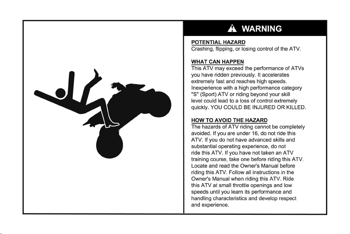
POTENTIAL HAZARD
Given the realities of spor t ATVs and/or the limit s of your ow n ridin g abilitie s, you may lo se co nt ro l. The limits ar e impos sib le to be sp ecific about becau se o f
the variation in terrain and rider abilit y are ne ar ly unlimited. If you chose to r ide an ATV, you must understand and resp ect the reality of the above.
WHAT CAN HAPPEN
You could lose control, have an accident an d be se ver ely injured, paralyzed or killed .
exposed, unprotected
Relatively easy to wheelie, requir es focus and ski ll to
stay ahead of machine
pitch over forward
Relatively easy to turn over
Grip on hard surface (pa ve me nt ) mak es it easy to turn
over
HOW TO AVOID THE HAZARD
The hazards of ATV riding can not be comple tely avoided. They can be minimized with training, good judgement, experience, use of helmet, protective gear and
development of sk ills in weight shifting, throttle an d br ak e con tr ol . Reading and understandin g thi s Owne r’s Manual and warning labels, watching and understanding the ATV safety video and completing an ATV training course are essential and can begin your learning process.
1
Page 4

FOREWORD
Experienced Riders Only
All Cannondale motorsports products are high
performance, sport and/or competition machines and
should only be operated by licensed competit ion riders in
excellent p hysical condition. Operators should be welltrained and experienced in the operation of high
performance com petition vehicles.
• This vehicle is not for beginners or the
inexperienced.
• Before you ride this vehicle, read this Owner’s
Manual thoroughly and understand all of the
instructions, warnings, cautions, and notes
presented.
• Read and understand the entire procedure before
performing any work. If you are unfamiliar with or
doubt your own abilities to complete a procedure
as described, have an authorized Cannondale
motorsports dealer service your vehicle.
For detailed service information, obtain the engine
service or chassis man ual for your vehicle or contact an
authorized Cannondale motorsports dealer for a list of
available publi cations.
Addenda to this manual
Before you begin reading the manual, go to the
“Addenda” section at the end of this manual. The addenda
or “supplements” section provides any additional,
replacement, or supplemental information for your product
available at the time of shipment.
About this manual
The purpose of this manual is to provide the vehicle
owner with important safety, service, maintenance, and
tuning information. Read and understand this manual
before operating or working on the vehicle. Keep your
Owner's Manual on the vehic le while you ride. If you lose
this manual, contact an authorized Cannondale
motorsports dealer for a replacement.
• This manual contains standard ATV industry
safety information required to be a part of ATV
Owner’s Manuals. It also contains Cannondale
specific model information.
2
Comments?
If you have any comments or suggestions about this
Owner’s manual, we’d appreciate hearing from you. Send
to:
Technical Publications
Cannondale Corporation
2 Corporate Drive
Bedford, PA 15522
E-mail:
technical.publications@cannondale.com
Page 5

Noise Regulation
TAMPERING WITH NOISE CONTROL SYSTEM
PROHIBITED
U.S. federal law prohibits the following acts or the
causing thereof;(1) The removal or rendering inoperative
by any person, other than for purposes of maintenance,
repair or replacement, of any device or element of design
incorporated into any ne w ve hic le for the purpose of noise
control prior to its sale or delivery to the ultimate purchaser
or while it is in use; or (2) the use of the vehicle after such
device or element of design has been rem oved or rendered
inoperative by any person.
AMONG THOSE ACTS PRESUMED TO CONSTITUTE
TAMPERING ARE THE ACTS LISTED BELOW:
1. Removing, puncturing, or altering of the muffler, the
baffle system, header pipes, or any other component
which conduct s exhaust gases.
2. Lack of proper m ai ntenance.
3. Replacing, altering, modifying any moving part of the
vehicle or parts of the exhaust, intake (e.g. air filters)
with parts other than those specified by the
manufacturer.
Limitations
All information in this O wner’s Manual i s based up on the
latest product data and specifications available at the time
of printing. Cannondale Corp oration reserves the right to
make product changes and improvements which may
affect illustrations, photographs and explanations
contained in this Owner’s M anual.
No part of this publication may be reproduced, stored in
a retrieval system, or transmitted in any form or by any
means, (electroni c mec ha nic al photocopying, recordi ng or
otherwise), without the prior written permission of
Cannondale Corporatio n. No li abi lity can be accepted for
any inaccuracies or omiss ion s in this pu bli ca t io n, alth ough
every possible care has been taken to make it as complete
and accurate as possible. All the procedures and
specifications found in this publication are subject to
change without prior notice and without Canno nda le
Corporation incurring any obligation. The illustrations in
this publication are intended for reference use only and
may not depict the actual model or component parts. Your
model may differ.
If you have questions about this Owner’s Manual call:
1-800-MOTO-USA.
3
Page 6
SAFETY ALERTS
• FAILURE TO FOLLOW THE WARNINGS CONTAINED IN THIS MANUAL CAN RESULT IN SERIOUS INJURY OR
DEATH.
• Keep this Owner’s Manual with your v ehicle at all times.
Messages with the Safet y Alert Symb ol
• Pay special attention to all messages preceded by the Safety Alert Symbol. It means ATTENTION! BEC OME
ALERT! YOUR SAFETY IS INVOLVED.
Indicates that severe personal injury or
DANGER
death WILL result if instructions are not
followed.
WARNING
Indicates a potential hazard that COULD
result in serious injury or death.
CAUTION
Indicates a potential hazard which that could result in vehicle damage if instructions are not followed.
NOTE :
Provides helpful inform atio n.
4
Page 7

SPECIAL SAFETY MESSAGES
• AN ATV IS NOT A TOY AND CAN BE HAZARDOUS
TO OPERATE
• An ATV handles differently from other vehicles
including motor cycles and cars. A collision or
rollover can occur quickly, even during routine
maneuvers such as turning and driving on hills or
over obstacles, if you fail to take proper
precautions.
• Severe injury or Death can result if you do not
follow the se instructions:
• Read this manual and all labels carefully and
follow the operating procedures described.
• Never operate an ATV without proper instruction.
Take a training course. Beginners should receive
training from a certified instructor. Contact an
authorized ATV dealer or call 1-800-887-2887 (USA
only) to find out about the traini ng courses nea rest
you.
• Always follow the age recommendation: A child
under 16 years old should never operate an ATV
with engine size greater than 90cc.
• Never allow a child under age 16 to operate an ATV
without adult supervision, and never allow
continued use of an ATV by a child if he or she
does not have the abilities to operate it safely.
• Never carry a passenger on a ATV.
• Never operate an ATV on any paved surfaces,
including sidewalks, driveways, parking lots and
streets.
• Never operate an ATV on any public street, road or
highway, even a dirt or gravel one.
• Never operate an ATV without wearing an
approved motorcycle helmet that fits properly. You
should also wear eye protection (goggles or face
shield), glove s, boots , long-s lee ved sh irt or jac ket,
and long pants.
• Never consume alcohol or drugs before or while
operating this ATV.
• Never opera te at e xces sive sp eed s. Al ways go at a
speed that is proper for the terrain, visibility,
operating conditions, and your experience.
• Never attempt wheelies, j umps or other stunts.
• Always inspect your ATV each time you use it to
make sure it is in safe operating condition. Alw ays
follow the in spection and maint enance proc edures
and schedules described in this manual.
• Always keep both hands on the handlebars and
both feet on the footpegs of the ATV during
operation.
• Always go slowly and be extra careful when
operating on unfamiliar terrain. Always be alert to
5
Page 8

changing terrain conditions when operating the
ATV.
• Never operate on excessively rough, slippery or
loose terrain until you have learned and practiced
the skills necessary to control the ATV on such
terrain. Always be espe cia lly cautious on these
kinds of terrain.
• Always f ollo w pr oper pro cedures f or turning at lo w
speeds before attempting to turn at faster speeds.
Do not turn at excessive speed.
• Never operate the ATV on hills too steep for the
ATV or for your abilities. Practice on smaller hills
before attempting larger hills.
• Always f ollo w pr oper pr ocedu res f or climbin g hills
as described in this manual. Check the terrain
carefully before you start up any hill. Nev er c l imb
hills with excessively slippery or loose surfaces.
Shift your weight forward. Never open the throttle
suddenly or make sudden gear changes. Never go
over the top of any hil l at high speed.
• Always follow proper procedures for going down
hills and for braking on hills as described in this
manual. Check the terrain carefully before you
start down any hill. Shift your weight backward.
Never go down a hill at high speed. Avoid going
down a hill at an angle that would cause the
vehicle to lean sharply to one side. Go straight
down the hill where possib le.
• Always follow proper procedures for crossing the
side of a hill as described in this manual. Avoid
hills with excessively slippery or loose surfaces.
Shift your weight to the uphill side of the ATV.
Never attempt to turn the ATV around on any hill
until you have mastered the turning technique
described in this manual. Avoid hills with
excessivel y slip pery or loose surfac es. Shift your
weight to the uphill side of the ATV. Never attempt
to turn the ATV around on an y hill until you have
mastered the turning technique described in this
manual on le vel gr ound. Avoid c ro ssing the s ide of
a steep hill if possible.
• Always use proper procedures if you stall or roll
backwards wh en climbing a hill. To avoid stalling,
use the proper gear and maintain a steady speed
when climbing a hill. If you stall or r oll backwards,
follow the s pecial p roc edure f or braki ng descr ibed
in this manual.
• Always c heck for obstacles before operating in a
new area. Never attempt to operate over large
obstacles, such as large rocks or fallen trees.
Always follow proper procedures when operating
over obstacles as described in this manual.
• Always be careful when skidding or sliding. Learn
to safely contr ol skidding or sliding by pract icing
at low speeds and on level, smooth terrain. On
extremely s lippery surfaces, s uch as ice, go s lowl y
6
Page 9

an be very cautious in order to reduce the chance
of skidding out of control.
• Never operate an ATV in fast flowing water or in
water deeper than that specified in this manual.
Remember that wet brakes may have reduced
stopping ability. Test you brakes after leaving
water. if necessary, apply them several times to let
friction dry out the linings.
• Always use the size and type of tires specified in
this manual. Always maintain proper tire pressure
as described in this manual.
• Never modify an ATV through improper installat ion
or use of accessories.
• Never install a twist grip throttle on this ATV.
• Never exceed the sta ted load lim its for an ATV.
Cargo should be pro perl y distrib uted and secure ly
attached. Reduce speed and follow instructions in
this manual for carrying cargo. Allow greater
distance for braking.
• FOR MORE INFORMATION ABOUT ATV SAFETY,
call the Consumer Product Safety Commission at
1-800-638-2772, or the
ATV Distributors’ Safety Hotline
at 1-800-852-5344 (USA only).
7
Page 10

When reading this manual, remember:
WARNING
Indicates a potential hazard
that COULD result in serious
injury or death.
CONTENTS
ATV SPORT REALITY - - - - - - - - - - - - - - 1
FOREWORD- - - - - - - - - - - - - - - - - - - 2
SAFETY ALERTS - - - - - - - - - - - - - - - - 4
SPECIAL SAFETY MESSAGES - - - - - - - - - 5
CONTENTS - - - - - - - - - - - - - - - - - - - 8
WARNING LABELS - - - - - - - - - - - - - - 10
MACHINE IDENTIFICATION - - - - - - - - - - 14
Vehicle Identification Number (VIN) - - - - - - - - 14
Engine Serial Number- - - - - - - - - - - - - - - 15
Key ID Number - - - - - - - - - - - - - - - - - - 15
PARTS AND CONTROL FUNCTIONS - - - - - 16
Owner’s Manual- - - - - - - - - - - - - - - - - - 18
Seat - - - - - - - - - - - - - - - - - - - - - - - 18
Ignition Switch- - - - - - - - - - - - - - - - - - - 21
Tether Switch - - - - - - - - - - - - - - - - - - - 22
Engine Stop/Start Buttons (MC500) - - - - - - - - 23
Engine Stop Switch/ Start Button (MC1000) - - - - 24
Headlights - - - - - - - - - - - - - - - - - - - - 25
Taillight - - - - - - - - - - - - - - - - - - - - - - 25
Front Brake Lever - - - - - - - - - - - - - - - - - 26
Parking Brake - - - - - - - - - - - - - - - - - - - 26
Rear Brake Pedal - - - - - - - - - - - - - - - - - 28
Footpegs & Baskets - - - - - - - - - - - - - - - - 28
Nerf Bars - - - - - - - - - - - - - - - - - - - - - 29
Shift Lever- - - - - - - - - - - - - - - - - - - - - 30
Fuel Tank Cap- - - - - - - - - - - - - - - - - - - 30
Handle Grips - - - - - - - - - - - - - - - - - - - 31
Throttle Lever - - - - - - - - - - - - - - - - - - - 32
Clutch lever (manual) - - - - - - - - - - - - - - - 33
Clutch lever (hydraulic) - - - - - - - - - - - - - - 33
Fuse & Diagnostics Connector - - - - - - - - - - - 34
Safety Flag Mount - - - - - - - - - - - - - - - - - 35
SAFE OPERATION- - - - - - - - - - - - - - - 36
Experienced Riders Only! - - - - - - - - - - - - - 36
Training and Instruction - - - - - - - - - - - - - - 37
Age Recommendation - - - - - - - - - - - - - - - 38
Wear Protective Gear - - - - - - - - - - - - - - - 39
Ride Sensibly - - - - - - - - - - - - - - - - - - - 40
No Passengers: No Exceptions! - - - - - - - - - - 41
Cargo, Loading Limit- - - - - - - - - - - - - - - - 42
Off-road Use Only - - - - - - - - - - - - - - - - - 43
Stay Off Public Roads and Highways- - - - - - - - 44
Turning The ATV - - - - - - - - - - - - - - - - - 45
Don’t Drink and Drive! - - - - - - - - - - - - - - - 46
No Wheelies, Stunts, or Jumps- - - - - - - - - - - 47
8
Page 11

Keep Your Hands and Feet on the Controls- - - - 48
Watch Out for Terrain Changes- - - - - - - - - - 49
Rough or Slippery Terrain - - - - - - - - - - - - 50
Stay Off Steep Hills- - - - - - - - - - - - - - - - 51
Climbing Hills Improperly - - - - - - - - - - - - - 52
Riding downhill - - - - - - - - - - - - - - - - - - 53
Crossing Slopes or Hills - - - - - - - - - - - - - 54
Turning on Slopes or Hills - - - - - - - - - - - - 55
Obstacles - - - - - - - - - - - - - - - - - - - - 56
Skidding or Sliding - - - - - - - - - - - - - - - - 57
Safety Flag- - - - - - - - - - - - - - - - - - - - 58
Riding Through Shallow Water - - - - - - - - - - 59
Stalling, Rolling Backwards- - - - - - - - - - - - 60
Modifications- - - - - - - - - - - - - - - - - - - 61
PRE-RIDE INSPECTION- - - - - - - - - - - - 62
Pre-Ride Checklist - - - - - - - - - - - - - - - - 63
OPERATION- - - - - - - - - - - - - - - - - - 64
BREAK-IN - - - - - - - - - - - - - - - - - - - 67
MAINTENANCE & ADJUSTMENT - - - - - - - 68
Work safely - - - - - - - - - - - - - - - - - - - 68
Maintenance Schedule - - - - - - - - - - - - - - 72
Panels - - - - - - - - - - - - - - - - - - - - - - 75
Frame, Subframe, Swingarm - - - - - - - - - - - 80
Fuel - - - - - - - - - - - - - - - - - - - - - - - 82
Engine Oil - - - - - - - - - - - - - - - - - - - - 85
Transmission Oil - - - - - - - - - - - - - - - - - 91
Coolant - - - - - - - - - - - - - - - - - - - - - 95
Brakes - - - - - - - - - - - - - - - - - - - - - 100
Clutch - - - - - - - - - - - - - - - - - - - - - 109
Drive - - - - - - - - - - - - - - - - - - - - - - 116
Electrical - - - - - - - - - - - - - - - - - - - - 123
Air - - - - - - - - - - - - - - - - - - - - - - - 136
Exhaust - - - - - - - - - - - - - - - - - - - - 139
Suspension- - - - - - - - - - - - - - - - - - - 140
Wheels- - - - - - - - - - - - - - - - - - - - - 146
Tires - - - - - - - - - - - - - - - - - - - - - - 149
CLEANING- - - - - - - - - - - - - - - - - - -152
STORAGE - - - - - - - - - - - - - - - - - - -153
TRANSPORTING - - - - - - - - - - - - - - -154
TORQUE TABLE- - - - - - - - - - - - - - - -156
TROUBLESHOOTING - - - - - - - - - - - - -157
MAINTENANCE RECORD- - - - - - - - - - -160
2002 MODEL SPECIFICATIONS- - - - - - - -161
Engine - - - - - - - - - - - - - - - - - - - - - 161
Chassis - - - - - - - - - - - - - - - - - - - - 164
Suspension- - - - - - - - - - - - - - - - - - - 166
ATV LIMITED WARRANTY - - - - - - - - - -168
STOLEN UNITS - - - - - - - - - - - - - - - -169
CHANGE OF ADDRESS - - - - - - - - - - - -169
ADDENDA - - - - - - - - - - - - - - - - - - -170
9
Page 12
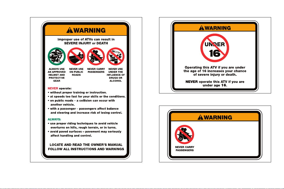
WARNING LABELS
Examples of all vehicle w arni ng lab els are found in this
section. Read and understand the actual ones on your
vehicle. The labels contain information which is im port ant
to your safety and that of anyone else who operates the
ATV.
• The warning labels should be considered
permanent parts of vehicle. Yes, just like the
wheels and engine, they are needed parts for any
operator.
• If any label is missing, worn, damaged, or
becomes unreadable, be sure to replace it.
Cannondale offers replacemen t labels at no
charge. A label’s part number is printe d in the
lower right corner of the label and here in the
manual. Contact an authorized Cannondale
motorsports dealer for replacements.
• Label locations are shown in the following
illustration. Examples of the labels are shown on
the following pages.
• Always replace labels in the correct position. See
the illustration for the correct location of the
warning labels on your vehicle.
(1)
(4)
(7)
(5)
(2)
(6)
10
(3)
Page 13
315-6000236-01
315-6000237-01
Label 2 P/N 315-6000237-01
Riding as a passenger can cause
the ATV to go out of control.
Loss of control can cause a
collision or rollover, which can
result in severe injury or death.
NEVER ride as a passenger.
315-6000239-01
Label 2 P/N 315-6000236-01
Label 3 P/N 315-6000239-01
11
Page 14
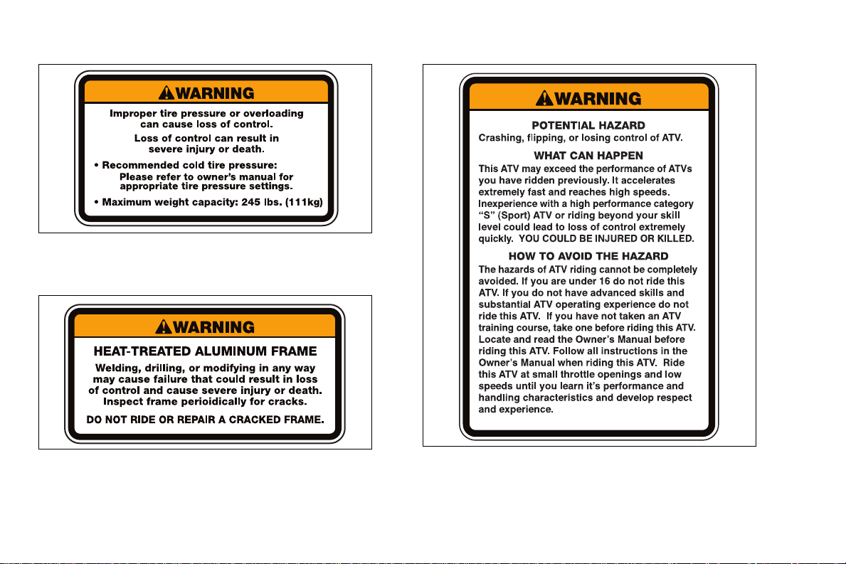
315-6000238-01
Label 4 P/N 315-6000238-01
315-6000477-01
Label 5 P/N 315-6000477-01
12
315-6000580-01
Label 6 P/N 315-6000580-01
Page 15

Hangtag
All Cannondale ATVs are shipped w ith a r em ova bl e
hangtag attached to the handlebar. Like the vehicle’s
warning labels, this hangtag contains important information
for your safety. Read and understand it throroughly before
removing it.
13
Page 16
MACHINE IDENTIFICATION
NOTE :
Your vehicle may differ from those shown in the
illustrations in this manual.
Record your vehicle’ s identification numbe rs in the
spaces provided. Keep another record of the numbers in a
safe place; you may need the m for parts , serv ic e
information, or theft recovery.
Your vehicle’ s ID numbe rs ide ntify it from others of the
same model type.
(1)
(2)
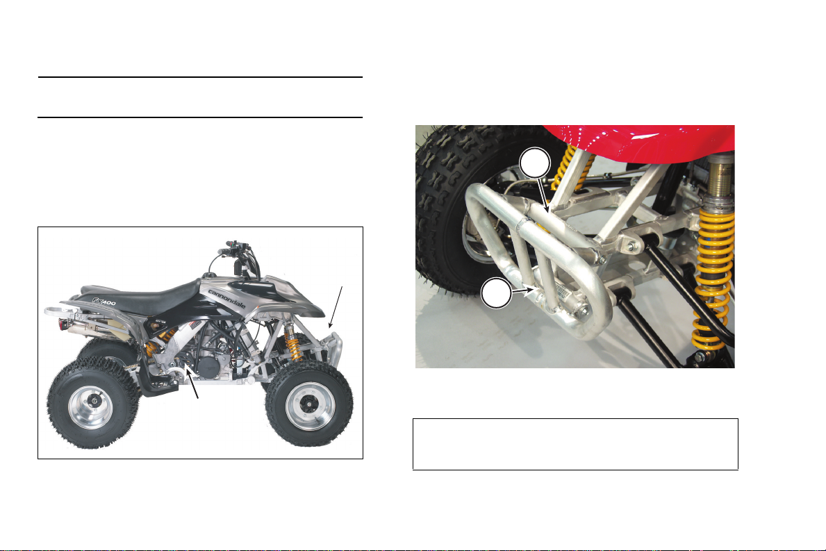
VEHICLE IDENTIFICATION NUMBER (VIN)
The vehicle identification number (VIN) is etched/
stamped into the frame behind the fron t brush gu ard. The
VIN also appears on a temporary factory applied adhesive
label in the same area.
1
2
1. Etched vehicle identification number
2. Factory VIN label
1. Vehicle identification number (VIN)
2. Engine serial number
14
Write your number here
Page 17
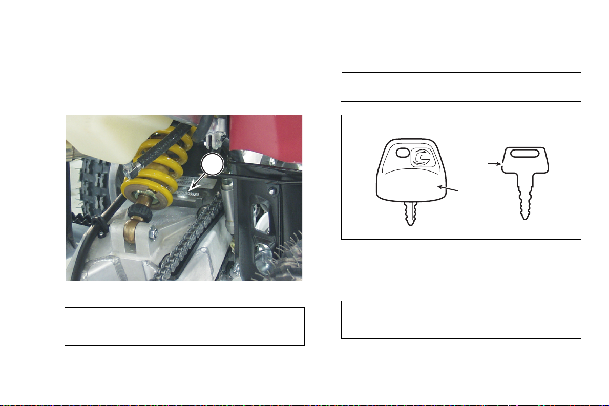
ENGINE SERIAL NUMBER
The engine serial nu mb er i s etch ed/ stamped into the
rear area of the engine crankcase. The number also
appears on a metalli c pla te affixed to the crankcase area
above the countersha ft sprocket. The number al so appears
on a temporary factory applied adhesive label in the same
area.
KEY ID NUMBER
Key identification numbers are etched/stamped into key
bodies.
NOTE :
Keep your spare key in a safe place in case you lose
the primary key.
1. Engine serial number
Write your number here
(1)
1
(3)
(2)
XXXXXX
(4)
1. Primary Key (remove housing to view ID number)
2. Spare key
3. Key ID number
4. Housing
Write your number here
15
Page 18
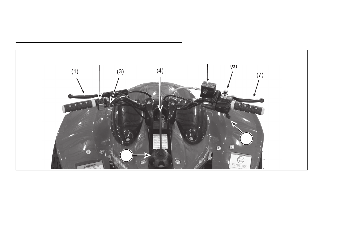
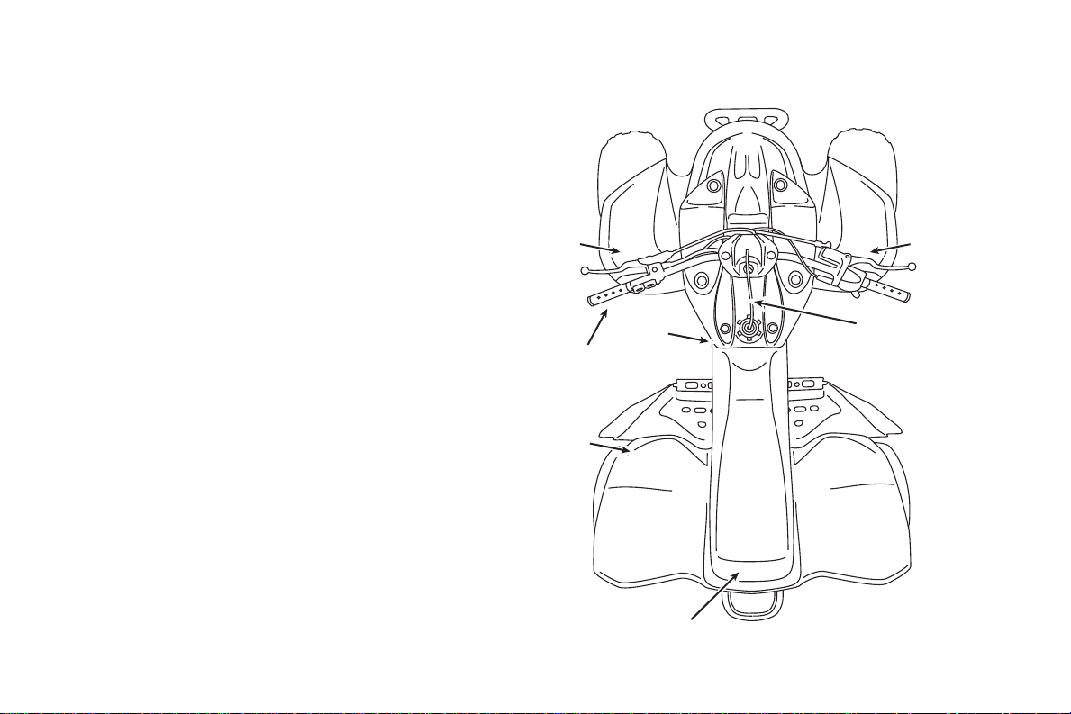
PARTS AND CONTROL FUNCTIONS
8
9
(2)
(5)
NOTE :
Your vehicle may differ slightly from those shown in the illustrations in this manual.
1. Clutch lever
2. Engine RUN/OFF switch
3. Engine start switch (green)
16
4. Ignition switch
5. Front brake master cylinder
6. Parking brake lock
7. Front brake lever
8. Throttle
9. Fuel cap
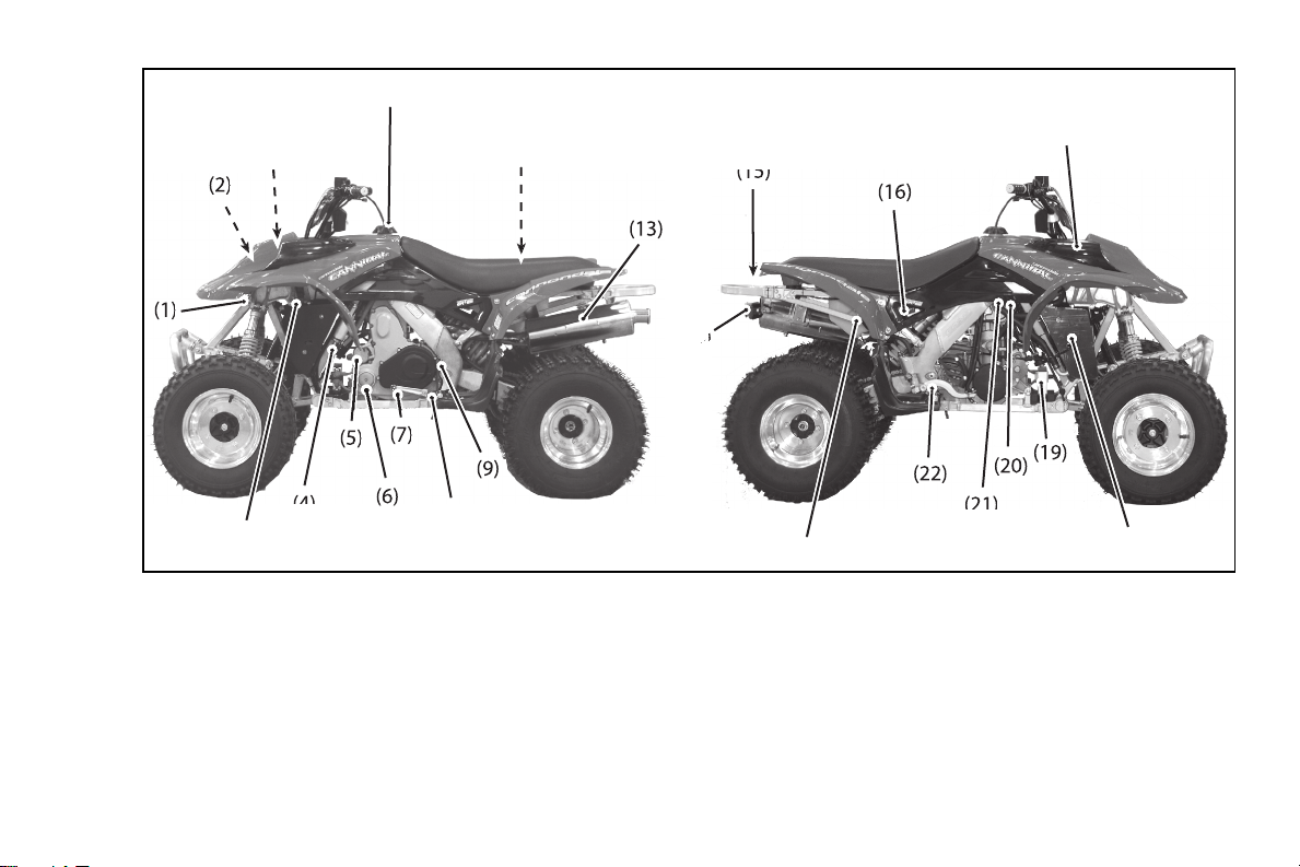
Page 19
(12)
(11)
()
(3)
(4)
(8)
(10)
(14)4)4)
(3)
(18)
(17)
(21)
1. Rectifier/regulator
2. Engine Control Unit (ECU)
3. Diagnostic connector & fuse
4. Fuel pump
5. Starter
6. Engine oil filter (1 of 2)
7. Shift lever
8. Transmission oil level check
9. Left frame spar drain bolt
10. Air filter
11. Fuel cap
12. Owner’s Manual
13. Muffler
14. Taillight
15. Safety flag mount
16. Fuel filter
17. Engine oil, coolant levels check
18. Radiator
19. Battery
20. Coolant bleed bolt
21. Right frame spar drain
22. Rear brake pedal
17
Page 20
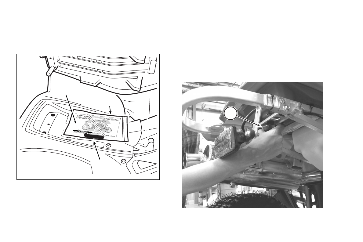
OWNER’S MANUAL
The Owner’s Manual for your vehicle is located under
the seat. It contains important safety and maintenance
information. Keep it on the vehicle when you ride. To find
the manual, remove the seat.
(1)
(3)
SEAT
The seat on your vehicle is for you only. Carrying a
passenger can cause you to lose control of the vehicle.
The entire length of the seat is required so that you can
shift body weight/position while riding to maintain vehicle
control and stabilit y. Make sure the seat is in good
condition and fasten ed se curely before you ride.
1. To remove the seat, loosen and completely remove the
seat retention bolt.
1
1. Owner’s manual
2. Low pressure tire gauge
3. Vinyl bag
18
(2)
1. Seat retention bolt
a
b
Page 21
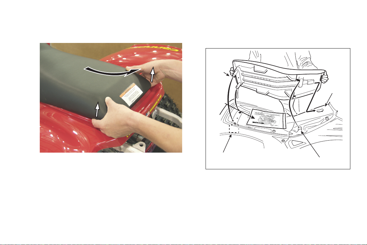
2. Use your fingertips to lift up the rear of the seat slightly.
Then, pull the seat back toward the rear of the vehicle
and lift it off.
4. Press down gently on the middle of the seat and slide
the seat forward onto the clip and subframe guides. If
correctly aligned, the rear seat pegs will slip easily
through the subframe seat buffers.
(3)
(1)
(5)
3. To install the seat, align the receivers in the seat pan
with the fuel tank clip and the subframe guides.
(4)
1. Fuel tank clip
2. Subframe guides (right)
3. Seat pegs
4. Subframe seat buffers (right)
5. Owner’s Manual & Tool Kit
(2)
19
Page 22

WARNING
POTENTIAL HAZARD
Loose, damaged, or improperly installed seat
WHAT CAN HAPPEN
The seat can shift or come off while you are riding
causing you to lose control of the vehicle. You can
be severel y injur ed or kil led.
HOW TO AVOID THE HAZARD
Always make sure the seat is locked into position
on the mounts and secured properly with the
retention bolt. Never ride this ATV with a damaged
seat. Have it replaced.
CAUTION
Do not force the seat pegs through the holes in the
rear fende r o r sub f ra me buf f er s; y ou c o ul d damage
the seat.
Avoid excessive force.
When reading this manual, remember:
WARNING
Indicates a potential hazard
that COULD result in serious
injury or death.
5. Install the seat retenti on bolt and tighten it securely.
20
Page 23
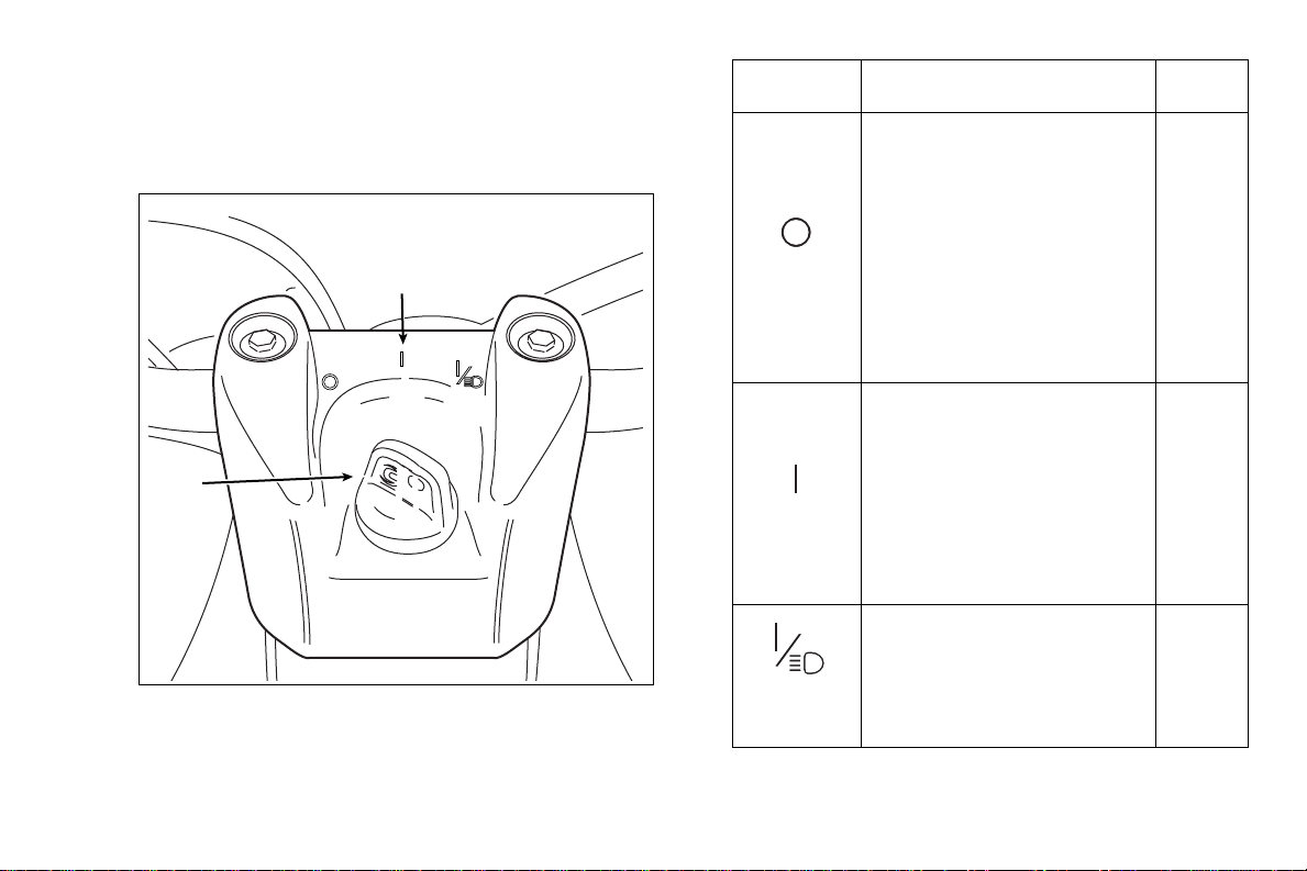
IGNITION SWITCH
The ignition switch is located between the handlebars.
Always remove the key from the switch to help prevent
unauthorized vehicle use or theft. See the table for a
description of the switch positions.
(2)
(1)
Key Position Function
The engine and lighting
cannot be operated.
Turning th e igni tion s wi tc h to
the “OFF” position, will stop a
running engine, however, we
recommend using the engine
“OFF”
“ON”
stop button (or switch) as the
primary me ans to shut off a
running engine - follow-up by
turning the switch to the “OFF”
position.
With the Engine Stop switch
in the “RUN” position and the
clutch lever pulled in, the e ngi ne
can be started using the Engine
Start button.
We recommend starting the
engine with the ig nit ion switch in
the (I) position then switch to the
“ON w/LIGHTS” position
Key
Removal
Yes
No
1. Ignition switch (key shown inserted)
2. Switch positions
“ON w/
LIGHTS”
Lighting (headligh ts and
taillight are activated.
No
21
Page 24
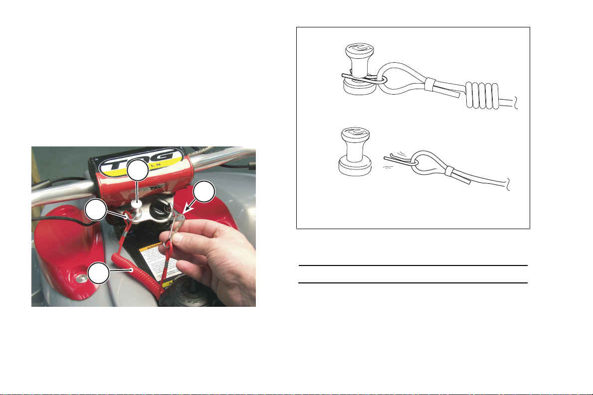
TETHER SWITCH
On equipped models, the tether switch is an additional
safety device. Test for proper operation of the switc h before
riding. The switch mus t be i n the ope rating position to start
the vehicle. To test the switch, make sure the switch pin is
inserted correctly. Start the engine. With the engine
running, pull the strap quic kl y fr om the sw i tc h body the
engine should shut down imme diatel y. If it does not, do not
ride the ATV; the switch is damaged and must be replaced.
Contact your dealer for a replacement.
1
4
2
3
1. Switch body
2. Tether pin
3. Tether strap
4. Body clip (to be secured to the rider)
(1)
(2)
1. Tether switch in operate position
2. Detached position
NOTE :
Body clip attachment to rider not illustrated.
22
Page 25
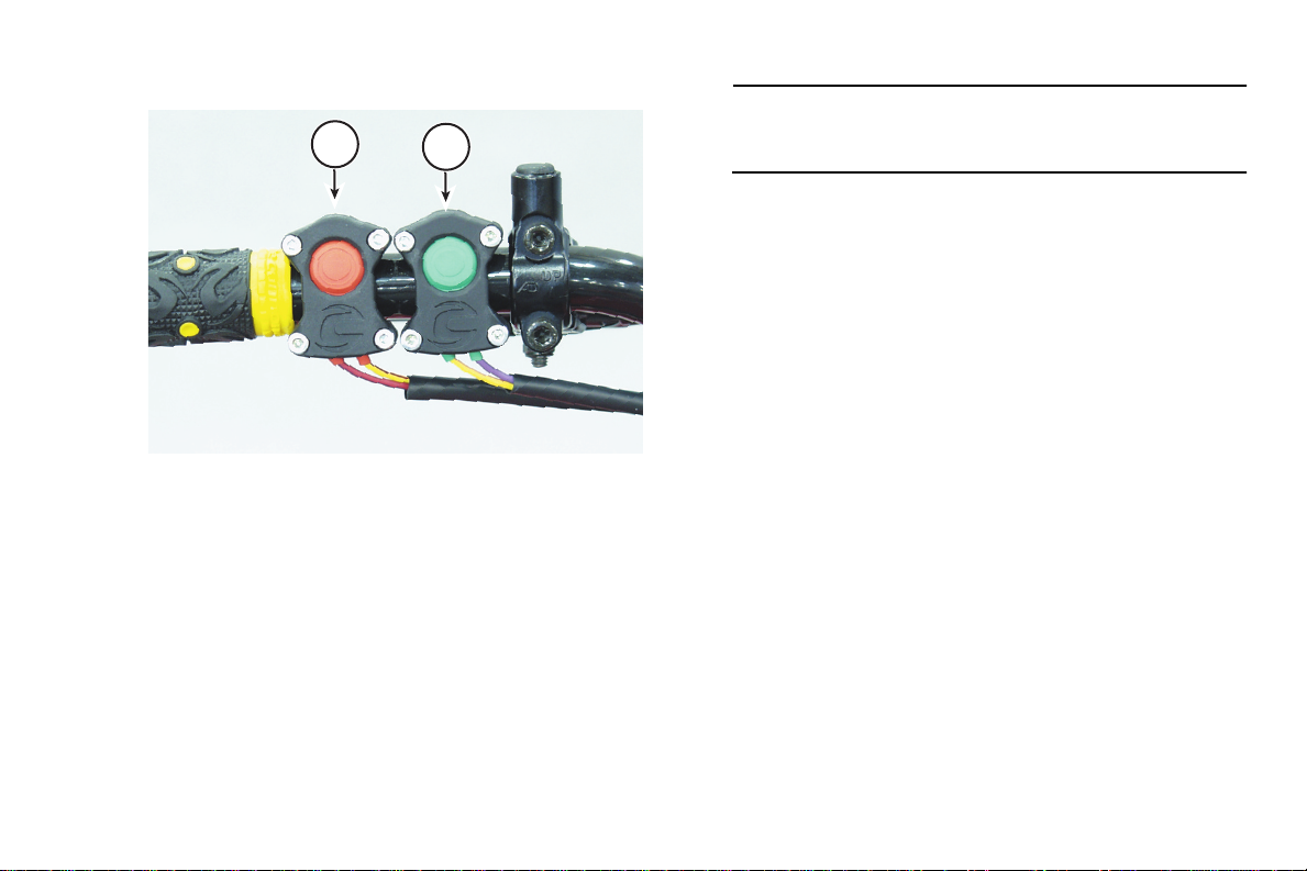
ENGINE STOP/START BUTTONS (MC500)
1
1. Engine stop button
2. Engine start button
2
Engine stop button
The engine st op button is located on the left handlebar
close to the inside edge of the handle grip and is red in
color. Press the stop button to shut off the running engine.
It is also an emergency con trol. Test the stop button before
moving off to ride to confirm that it is operating properly. If
the switch does not “kill” the engine, don’t ride the ATV.
Turn the i gn itio n s witc h to t he “OFF” position and contact a
Cannondale motorsports dealer to have it replaced.
NOTE :
The stop button is a “normally closed” circuit switch. If
the switch is damaged or the wires are frayed or torn,
(i.e. circuit open) the engine will not start.
Engine start button
The engine start button is green in c ol or and is mounted
closer to the center of the handleb ars. Pressin g it activate s
the engine management system ci rcuits and the starter
motor. Make sure it operates properly before each ride.
23
Page 26
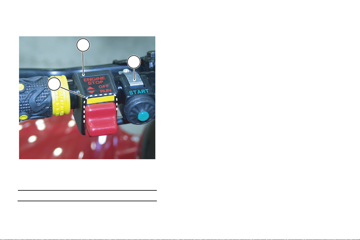
ENGINE STOP SWITCH/ START BUTTON (MC1000)
1
1
2
2
a
1. Engine OFF/RUN Switch
2. Engine start button
a. OFF posi t ion
NOTE :
The switch is show n in the R UN positi on in this photo.
Engine stop switch
The engine stop switch is located on the left handlebar
close to the inside ed ge of the han dle grip and is the sli ding
type with two positions. Sliding the switch to the “OFF”
position will deactivate the Engine Management System
and is the recommend ed me thod to stop the engin e while it
is running as opposed to using the ignition switch. This
switch is also an e m ergency contr ol used t o shut down the
engine quickly with your thumb without removing your
hands from the handle grip. This switch must be
maintained nearer the handle grip for this reason. During
your pre-ride inspection an d before movin g of f to ride, start
the engine and test the swi tch to confi rm that i t is o peratin g
properly. If the switc h does not “kill” a running engine, d on’t
ride the ATV. Remove the key from the ignition switch to
prevent vehicle use and contact an Cannondale
motorsports dealer for servicing.
Engine start button
The engine start button is green in c ol or and is mounted
closer to the center of the handleb ars. Pressin g it activate s
the engine management system ci rcuits and the starter
motor. Make sure it operates properly before each ride.
24
Page 27
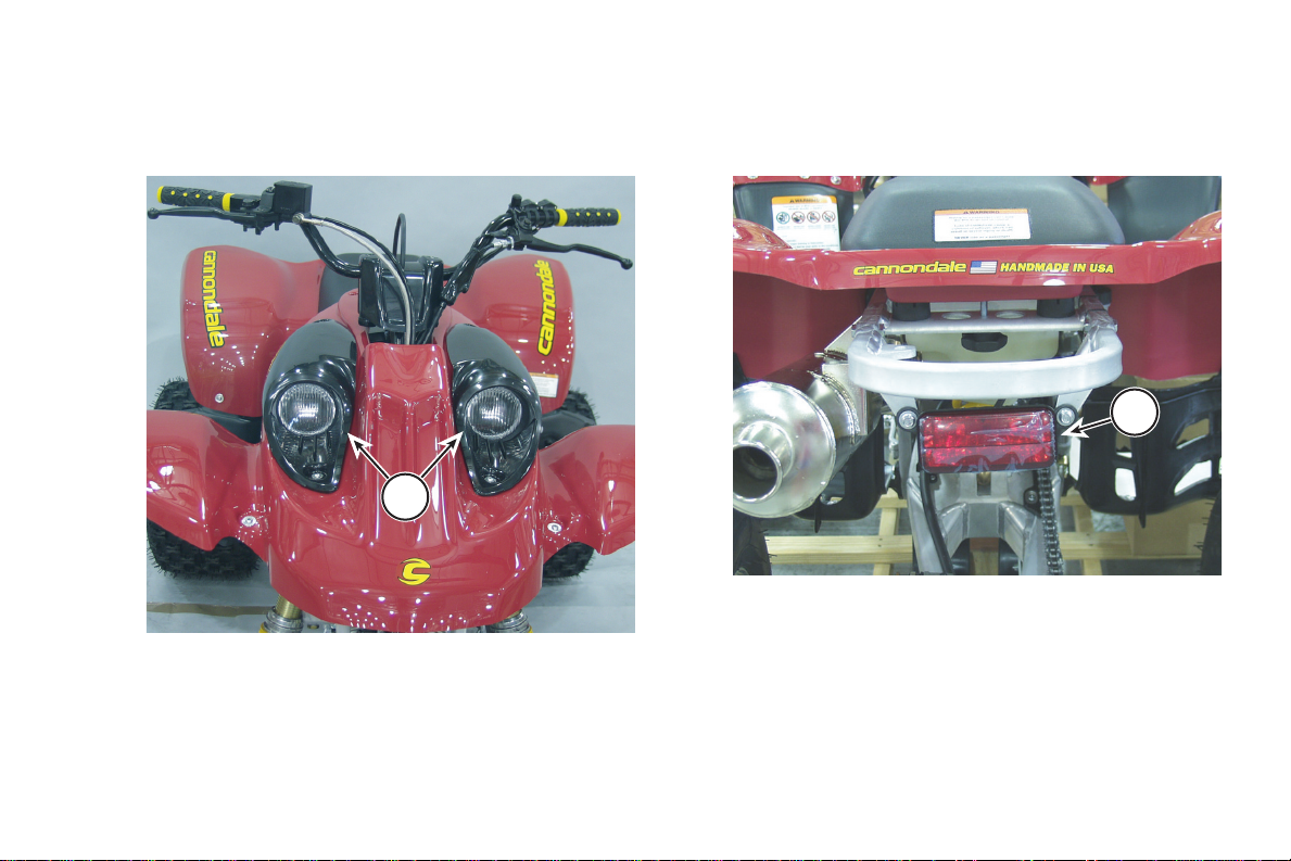
HEADLIGHTS
Turn the ignition switch to the “ON w/LIGHTS” position
to activate the headlights. Test for the proper operation of
the headlights before op erating the vehicle.
1
1. Headlights
TAILLIGHT
Turn the ig nition swi tch to the “ON with L IGHT S” positio n
to activate the taill igh t. T he tail lig ht I S NOT a brake ligh t.
Make sure it works before every ride.
1
1. Taillight
25
Page 28
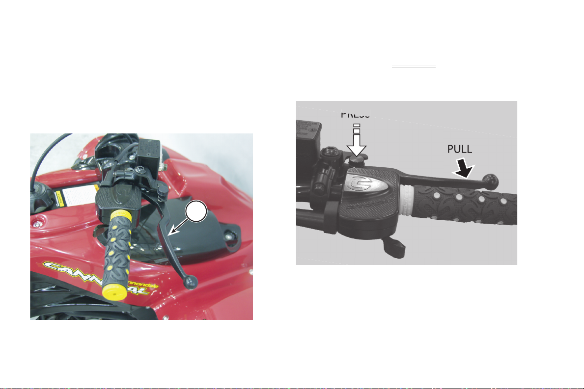
FRONT BRAKE LEVER
The front brake lever is located on the right side of the
handlebar. Pull it toward the handlebar to apply the front
brakes. Pull the lever harder to increa se brak in g force .
Before each ride, make sure the front brake s are
operating properly and can provide braking force when
needed. Roll the v ehicle forward and back apply ing the
brake to confirm that brak in g force is applied to the front
brake discs.
1
Front brake lever view
PARKING BRAKE
The parking brake is ap plied with a lock button on the
front brake lever. When the parking brake is applied
(locked), the front brakes temporarily
from rolling. Be sure to read the warning about using the
parking brake!
prevent the vehicle
1. Front brake lever
26
Page 29

WARNING
POTENTIAL HAZARD(S)
(1) ATV rolling away
(2) Riding with the parking brake applied
WHAT CAN HAPPEN
(1) A potential decline in fluid pressure can
decrease the applied braking force allowing the
ATV to begin to roll.
(2) Brake system will overheat, cause premature
wear, and damage to the brake pads. This can
result in a loss of brake function.
In either case above, severe injury or death can
result to the owner or bystanders.
HOW TO AVOID THE HAZARD
(1) Always block or chock the wheels on your ATV
immediately after applying the parking brake.
Never apply the parking brake and leave the
vehicle unattended.
Always choose firm level ground on which to park
your ATV.
(2) Release the parking brake before you ride.
your index finger until it is fully depressed - release the
lever and remove your index finger from the button.
2. To disengage the parking br ak e , pres s do wn on the re ar
brake pedal with your foot. Then, pull the front brake
lever against the handle grip; the locking mechanism
will automatically disengage (pop up).
3. Release the front bra ke lev er slowly.
1. To apply, pull the front brake lever against the handle
grip and hold it. Press and hold the locking button with
27
Page 30
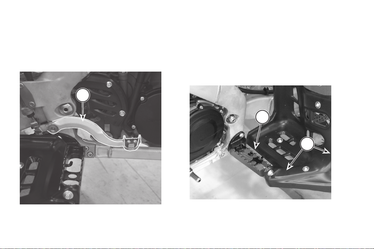
REAR BRAKE PEDAL
The rear brake pedal is located on the right side of the
vehicle. When pressed, braking forc e is appli ed to the rear
wheels. Make sure the rear brake is operating properly
before you ride. Roll the vehicle forward and back and
press the pedal to confirm that braking force is applied to
the rear brake disc.
1
FOOTPEGS & BASKETS
When riding always keep your feet on the footpegs.
Always check the condition of the footpegs and baskets
before every ride. Make sure that they are fastened
securely to the vehicle. The footpeg teeth should be in
good condition (not smooth or wo rn exc es sive ly). The
baskets should be free of an y packed soils an d they sh ould
not be cracked, broken, or dam aged in any way. If damage
is found install new ones.
1
2
1. Rear brake pedal
28
1. Foot peg (left)
2. Basket
Page 31

NERF BARS
NRF BAR
Always check the condition of the nerf bars, strapping,
and footpe g teeth before every ride. Make sure that t hey
are fastened securely to the vehicle and that the footpeg
teeth and webbing is in good condition and does not sag
excessively when the weight of the rider is applied. Pay
particular attention to strapping in the areas where it
attaches to the bars. See example at dotted circle in photo
below.
NURF BAR
2
1
2
1
1
3
1. Nerf bar (right)
2. Teeth (replacable)
3. Strapping
1
WARNING
POTENTIAL HAZARD(S)
Damaged webbing
WHAT CAN HAPPEN
Foot can go through the bars while riding. You can
lose control and have a serious accident.
HOW TO AVOID THE HAZARD
Inspect the webbing before you ride. If its
damaged don’t ride the vehicle. Replace it.
29
Page 32

SHIFT LEVER
5
The shift lever is located on the left side of the engine in
front of the left footpeg. The vehicle has five forward gears
(1-down,”NEUTRAL’” 4-up). Place the vehicle on a level
surface. Before every ride, make sure the shift lever
operates properly and shifts through the entire range of
gears with the engine turned off; roll the vehicle forward
and back as you shift through al l the gear s to av oi d
damaging the transmission.
FUEL TANK CAP
Make sure the fuel cap is tightly secured before every
ride. Turn the fuel cap counterclockwise to remove it and
clockwise to tighten it. Al ways make sure the breather hose
is routed from the cap p roperly (inse rted int o the ha ndleb ar
cover hole).
5
4
1. Shift lever
30
3
2
1
1
1. Fuel cap
2. Breather hose
3. Hole
Page 33

HANDLE GRIPS
Inspect both (left and ri ght) handl ebar grips before ever y
ride. Make sure th ey are firmly attached and do no t twist on
the handlebar. Inspect the grips for wear, tears, or other
damage. Replace the grips with a new set if damage is
found. Contact an authorized Cannondale motorsports
dealer for a replacement set.
1
1. Handle grip (right)
31
Page 34

THROTTLE LEVER
The throttle lever is located on the right side of the
handlebar. When pushed, the engine speed will increase.
When released, engine speed will decrease - the lever
spring pressure should return the lever to the set idle
(engine) speed. Check for proper operation and specified
freeplay of the throttle be fore every ride. See “2002 Model
Specifications” star ting on page 161.
Lever movement should work smoothly without binding
or pinching in all lever and handlebar positions.
DANGER
POTENTIAL HAZARD
Overturning or flipping the ATV onto yourself
NOTE :
Freeplay is the distance the lever moves until the slack
in the cable is taken up.
1
WHAT CAN HAPPEN
Opening the throttle too quickly and/or releasing the
clutch lever too quickly can overturn or “flip” the
ATV. You can be severely injured or killed.
HOW TO AVOID THE HAZARD
Never open the throttle abruptly. Open the throttle
gradually when moving off or accelerating. Never
“pop” or release the clutch lever quickly. Always
gradually release the clutch lever.
If the ATV “wheelies” or the front wheels begin to
come off the ground, close the throttle and pull in
the clutch lever immediately.
32
1
a
1. Throttle lever
a. Freeplay
Page 35

CLUTCH LEVER (MANUAL)
The clutch lever is lo ca ted on t he left side of the
handlebar. Pull in the clutch lever (quickly) to disengage
the clutch, and release the lever (slowly) to engage the
clutch. Check the condition and proper operation of the
clutch lever and cabl e be for e every ride. Als o make sure
the clutch lever freepla y is adjus ted to spe ci fic ati on. See
“Clutch lever (manual)” starting on page 33.
1. Clutch Lever
2. Starting system interlock switch
CLUTCH LEVER (HYDRAULIC)
The hydraulic clutch lever is located on the left side of
the handlebar. Pull in the clutch lev er (quickly) to
disengage the cl utc h, and release the lever (slowly) to
engage the clutch. The lever position can be adjusted for
individual hand sizes. See “Clutch lever position
(hydraulic)” starting on page 110.
3
2
1
1. Clutch Lever
2. Starting system interlock switch
3. Clutch reservoir
33
Page 36

FUSE & DIAGNOSTICS CONNECTOR
The main electrical fuse is located in the area under the
left front fender. Always replace the fuse with one of the
specified rating. See “Fuse” starting on page 130. A special
diagnostic tool co nne cto r is al so located in the same area.
The connector type is different for MC500 and MC1000
equipped models. Se e the photos. The diagnost ic tools ca n
be used to diagnose faults with the engin e management
system as well as other function s.
2
2
1
1. Fuse (in holder)
2. MC500 Data port
34
1
1. Fuse (in holder)
2. MC1000 Data port
NOTE :
For information on special tools developed to service
your ATV, contact an authorized Cannondale
motorsports dealer.
Page 37

SAFETY FLAG MOUNT
The safety flag mounting bracket is integrated into the
left side of the rear grab rail. When riding in areas where
you might not be eas il y seen (e.g. hilly terra in or san d
dunes) mount an approved ATV safety flag.
Safety flags are required i n some rid ing area s. For mo re
information on ap prov ed ATV safety flags, contact an
authorized Cannond ale motorsports deale r.
1
1. Safety flag mount
35
Page 38

SAFE OPERATION
When reading this manual, remember:
WARNING
Indicates a potential hazard
that COULD result in serious
injury or death.
EXPERIENCED RIDERS ONLY!
WARNING
POTENTIAL HAZARD
Crashing t he ATV
WHAT CAN HAPPEN
Cannondale ATVs are high-performance sport
category machines designed for competition use
only by operators who already have substantial skill
and operating experience. Operating without
substantial skill and operating experience increases
the risk that you could lose control of the vehicle
becoming severely injured or killed in a resulting
accident.
HOW TO AVOID THE HAZARD
If you do not have substantial skill and operating
experience, DO NOT OPERATE ANY CANNONDALE
ATV.
Always remove the ignition key from this vehicle to
prevent unauthorized use.
36
Page 39

TRAINING AND INSTRUCTION
The following warning message is required to be part of
this Owner’s Manual as part of an agre eme nt betwe en the
ATV Industry and the U.S. Consumer Product Safety
Commission (CPSC). The warning was written to
communicate the need for beginning and inexperienced
riders to get training and in struction before operating any
A TV. Although the mess age that train ing a nd i nst ructio n is
required for any beginning rider is correct, these riders
SHOULD NOT operate Cannondale ATVs. See the
warning on the previous page.
WARNING
POTENTIAL HAZARD
Operating this ATV without proper instruction.
WHAT CAN HAPPEN
The risk of an accident is greatly increased if the
operator does not know how to operate the ATV
properly in diff erent si tuations a nd on dif fer ent types
of terrain.
HOW TO AVOID THE HAZARD
Beginning and inexperienced riders should
complete the certified training course. They should
then regularly practice the skills learned in the
course and the operating techniques described in
this Owner’s Manual.
For more information about the training course,
contact an authorized Cannondale motorsports
dealer or call 1-800-887-2887 (USA only).
37
Page 40

AGE RECOMMENDATION
WARNING
POTENTIAL HAZARD
Failure to follow the age recommendation for this
ATV.
WHAT CAN HAPPEN
Use by children of ATV’s that are not recommended
for their age can lead to se ver e inju ry or death of the
child.
Even though a child may be within the age group for
which an ATV is recommended, he or she may not
have the skills, abilities, or judgement needed to
operate the ATV safely and may be involved in a
serious accident.
HOW
A CHILD UNDER 16 SHOULD NEVER OPERATE AN ATV WITH ENGINE SIZE GREATER
THAN 90CC.
38
Page 41

WEAR PROTECTIVE GEAR
The proper riding apparel (gear) can help reduce the
chance of injury in the ev ent of an accid ent and make
riding more comfortable.
WARNING
POTENTIAL HAZARD
Operating this ATV without wearing an approved
motorcycle helmet, eye protection and protective
clothing.
WHAT CAN HAPPEN
Operating without an approved motorcycle helmet
increases your chances of severe head injury or
death in the event of an accident.
Operating without eye protection can result in an
accident and increases your chances of severe eye
injury in the event of an accident.
Operating without prot ective c lo thing incre ases y o ur
chances of severe injury in the event of an accident.
HOW TO AVOID THE HAZARD
Always wear an ap pr o ved motor c yc le he lmet that fits
properly.
You should also wear: eye protection (goggles or
face shield), gloves, boots, long pants and a jacket
or long sleeved shirt.
Helmet
Goggles
Protective
clothing
Example of a properly dressed rider
Gloves
Boots
39
Page 42

RIDE SENSIBLY
Riding too fast increases your chances of an accident
occurring which could result i n a serio us inj ury or de ath, no
matter what your experience level.
Do not ride faster than what is appropriate for your skill
level and surrounding conditions.
Always reduce speed when rid ing at dusk, dawn, and
night. Riding at dusk, dawn, and nighttime, even with the
lighting on this ATV, reduces your ability to see obstacles;
therefore, you must slow down.
When reading this manual, remember:
WARNING
POTENTIAL HAZARD
Riding this ATV at excessive speeds.
WHAT CAN HAPPEN
Increases your chances of losing control of the ATV,
which can result in an accident.
HOW TO AVOID THE HAZARD
Always go at a speed that is proper for your vehicle,
the terrain, visibility and other operating conditions,
and your experience.
40
WARNING
Indicates a potential hazard
that COULD result in serious
injury or death.
Page 43

NO PASSENGERS: NO EXCEPTIONS!
Don’t carry a passenger on any ATV. Passenge rs will
interfere with your a bil ity to control the vehicle. A special
NO P ASSENGE RS warning label is affixed on the seat to
always remind you and those who ask for a ride. If
someone asks for a ride, refuse and ask them to read the
warning label on the rear of the seat. Then, explain that
your ATV has no seating space, footpegs, or grab rails for
his/her use. And, that the seemingly large seat is needed
for you to shift body position/weight as necessary when
riding. Also explain that if they put their feet on the footpegs
you will not be able to operate the foot controls (e.g. rear
brake, shift lever.
WARNING
POTENTIAL HAZARD
Carrying a passenger on this ATV.
WHAT CAN HAPPEN
Greatly reduces your ability to balance and control
this ATV. Passengers affect balance and steering
increasing the risk of losing control. Carrying a
passenger could cause an accident, resulting in
injury or death to you and/or your passenger.
HOW TO AVOID THE HAZARD
Never carry a passenger. The ATV has a long seat to
allow the operator to shift position as needed during
operation.
It is not for carrying passengers.
41
Page 44

CARGO, LOADING LIMIT
Do not carry cargo on your ATV. Do no t modify y our ATV
to carry cargo.
Do not exceed the veh ic le’s specified loadin g lim it.
Loading limit is defined as: the weight of the operator
(wearing all protective gear/apparel) - nothing else! Consult
the Model Specificati ons section of this Owner’s Manual for
your vehicle’s loading lim it. “2002 Model Specif ic atio ns ” on
page 161.
Exceeding the vehic le’s specif ied loadi ng limit will cause
a lose of stability and erratic handling that can res ul t in the
loss of vehicle cont rol. You could be involved in an accident
and be seriously injured or killed.
WARNING
POTENTIAL HAZARD
Overloading this ATV or carrying or towing cargo
improperly.
WHAT CAN HAPPEN
Could cause changes in vehicle handling which
could lead to an accident.
HOW TO AVOID THE HAZARD
Never exceed the stated load capacity for this ATV.
Cargo should be properly distributed and securely
attached.
Reduce speed when carrying cargo or pulling a
trailer. Allow greater distance for braking.
Always follow the instructions in your Owner’s
Manual for carrying cargo or pulling a trailer.
42
Page 45

OFF-ROAD USE ONLY
Stay off the public streets, highways, or any other paved
surfaces.
First, you risk a collisi on with othe r vehicles. Aside from
severely injuring or killing yo urs elf , you’ll probably injure or
kill a motorist. Second, no matter what speed you might
choose to attempt it, you can’t operate an ATV safely on a
public road or highway. The hard surface makes the
handling and stability of all ATVs wildly unpred ict able. You
can lose control sudden ly and withou t warning. The lig hting
on this ATV does not imply that it is for public roads or
highways.
WARNING
POTENTIAL HAZARD
Operating this ATV on paved surfaces.
WHAT CAN HAPPEN
The ATV and its tires are designed for off-road use
only. Paved surfaces may seriously affect handling
of the ATV which may cause you to lose control of
the vehicle.
HOW TO AVOID THE HAZARD
Never operate this ATV on any paved surfaces,
including sidewalks, driveways, parking lots and
streets. If you must ride on a paved surface, go
slowly and do not make sudden turns or stops.
43
Page 46

STAY OFF PUBLIC ROADS AND HIGHWAYS
0
8
WARNING
POTENTIAL HAZARD
Operating this ATV on public streets, roads or
highways.
WHAT CAN HAPPEN
You can collide with another vehicle.
HOW TO AVOID THE HAZARD
Never operate this ATV on any public street, road or
highway, even a dirt or gravel one.
In many states it is illegal to operate ATV’s on public
streets, roads and highways.
44
Page 47

TURNING THE ATV
Practice making turns in a large open area at sl o w
speeds to build experience before attemptin g more difficult
turns at increased speed.
To turn, slide forward on the seat and turn the
handlebars in the direction of the turn. Lean yo ur b ody to
the inside of the tu rn while maint aining the thro ttle po sitio n.
When the turn is compl ete, straig hten the handlebars and
return to a normal riding position.
The ability of the rea r inside wheel to slip during a turn
also depends on the ty pe of terrain where you are riding. If
the terrain is loose the inside wheel will slip more easily
and turns can be made in a smaller radius. If the terrain is
hard, where the insi de wh ee l is slippi ng less, the t urn ing
radius will be larger.
Always slow down before turning and reduce your
speed before entering a turn.
WARNING
POTENTIAL HAZARD
Turning improperly.
Removing your feet from the footpegs when turning.
WHAT CAN HAPPEN
The ATV can go out of control, causing a collision or
overturn.
Your foot can come in to contact with the rear wheel
resulting in severe personal injury.
HOW TO AVOID THE HAZARD
Always follow proper procedures for turning as
described in this Owner’s Manual.
Practice turning at low speeds before attempting to
turn at faster speeds.
Keep your feet on the footpegs when operating this
ATV.
Do not turn at excessive speeds.
If you have experience ridin g a motorcy cle yo u will have
to quickly “unlearn” the technique you might have
developed of removing your inside foot from the footpeg
and positioning it on the ground when making a turn. This
motorcycle technique will result in severe personal injury
and possibly a loss of control if a ttem pt ed on any ATV.
Never remove your feet from the footpegs while riding this
ATV.
45
Page 48

DON’T DRINK AND DRIVE!
ATV’s are no different than ca rs wh en it com es to
drinking an d driving. Do it and people wind up dying or
hurting themselves and others severely.
Alcohol impairs your judgement and slows yo ur
reactions - so stay off any ATV if you’ve been drinking
alcohol or taking drugs or medication. And, remember that
even prescription and over-the counter drugs can impair
your ability to safely operate this ATV. If you are taking a ny
type of medication, check with your doctor before riding.
WARNING
POTENTIAL HAZARD
Operating this ATV after consuming alcohol or
drugs.
WHAT CAN HAPPEN
Could seriously affect your judgment.
Could cause you to react more slowl y.
Could affect your balance and perception.
Could result in an accident.
HOW TO AVOID THE HAZARD
Never consume alcohol or drugs before or while
driving this ATV.
When reading this manual, remember:
WARNING
Indicates a potential hazard
that COULD result in serious
injury or death.
46
Page 49

NO WHEELIES, STUNTS, OR JUMPS
We urge you NOT TO DO STUNTS, ride sensibly. and
develop a healthy respect for the vehicle. All Cannondale
ATV’s are high-perfor m an ce vehicles. If the throttle is
opened abruptly and/or the clutch lever is released too
quickly the front w h eel s w ill c om e off the ground. This may
result in the vehicle overturning.
You will see people attempting jumps or other stunts
with ATVs. You’ll probably see someone do it in one of the
magazines or at an ATV event. What you could be seeing
is a professional rider or a weekend amateur. In any case,
whoever the jumper or stunter is, they are engaging in a
extremely high-risk activity which can result in crippling
injury or death.
WARNING
POTENTIAL HAZARD
Attempting wheelies, jumps, and other stunt s.
WHAT CAN HAPPEN
Increases the chance of an accident, including an
overturn.
HOW TO AVOID THE HAZARD
Never attempt stunts, such as wheelies or jumps.
Don’t be a show off!
47
Page 50

KEEP YOUR HANDS AND FEET ON THE CONTROLS
Riding ATV’s safely means being in complete control of
the vehicle at all times.
Always keep your hands on the handle grips and your
feet on the footpegs. By removing your hands and feet
from the handle grips an d footp egs you risk serious injury
and losing control of this ATV.
ATTENTION MOTORCYCLE RIDERS:
You may have a motorcycle riding technique to unlearn!
The common practice of removing a foot from your
motorcycle footpegs when rounding a turn is VERY
DANGEROUS if done on an ATV. If you take your foot off
the footpeg while turning the rear tires will run over your
foot or leg and cause severe injury - maybe even death.
WARNING
POTENTIAL HAZARD
Removing hands from handlebars or feet from
footpegs during operation.
WHAT CAN HAPPEN
Removing even one hand or foot can reduce your
ability to control the ATV or could cause you to lose
you balance and fall off the ATV. If you remove a foot
from the footpeg, your foot or leg may come into
contact with the rear wheels, which could injure you
or cause an accident.
HOW TO AVOID THE HAZARD
Always keep both hands on the handlebars and both
feet on the footpegs of your ATV during operation.
48
Page 51

WATCH OUT FOR TERRAIN CHANGES
Watch out for terrain changes or hidden hazards that
can cause you to lose control of the vehicle or collide with
unseen obstacles (e.g., gopher holes, logs, gullies, or
ditches). Always use caution in an unfamiliar area.
For example, never ride through an area where the view
of the ground surface is not clear (e.g., high-standing
grass, fallen branches, holes, large obstacles or other
hazards); you could co lli de with a hidden hazard an d be
seriously injured or ev en killed.
WARNING
POTENTIAL HAZARD
Failure to use extra care when operating this ATV on
unfamiliar terrain.
WHAT CAN HAPPEN
You can come upon hidden rocks, bumps, or holes
without enough time to react.
Could result in the ATV overturning or going out of
control.
HOW TO AVOID THE HAZARD
Go slowly and be extra careful when operating on
unfamiliar terrain.
Always be alert to changing terrain conditions when
operating the ATV.
49
Page 52

ROUGH OR SLIPPERY TERRAIN
Never operate on excessively rough, slippery or loo se
terrain until you have learned and practiced the skills
necessary to control the ATV on such terrain.
WARNING
POTENTIAL HAZARD
Failure to use extra care when operating on
excessively rough, slippery or loose terrain.
WHAT CAN HAPPEN
Could cause loss of traction or vehicle control,
which could result in an accident, including an
overturn.
HOW TO AVOID THE HAZARD
Do not operate on excessively rough, slippery or
loose terrain until you have learned and practiced
the skills necessary to control the ATV on such
terrain.
Always be especially cautious on these kinds of
terrain.
50
Page 53

STAY OFF STEEP HILLS
Never operate the ATV on hills too steep for the ATV or
for your abilities. Practice on smaller hills be fore attemp ting
larger hills.
Keep the front wheels on the gro und s o that you
maintain steering control and prevent the possibility of
overturning the ATV.
WARNING
POTENTIAL HAZARD
Operating on excessively steep hills.
WHAT CAN HAPPEN
The vehicle can overturn more easily on extremely
steep hills than on level surfaces or small hills.
HOW TO AVOID THE HAZARD
Never operate the ATV on hills too steep for the ATV
or for your abilities. Practice on smaller hills before
attempting larger hills.
51
Page 54

CLIMBING HILLS IMPROPERLY
Climbing hills is an advanced technique. Before
attempting to climb difficult hills, begin by practicing on flat
ground and then smalle r hills to build experience. Nev er
attempt a hill or slope beyond your skill level and evaluate
all hills and slopes carefully to avoid ter r ain that might
cause the ATV to overturn. Only attempt difficult hills and
inclines after you have developed considerable skill and
experience through study and practice.
When climbing hill s and slopes, shift your weight
forward toward the front wheels to help keep them from
lifting off the ground. Shift your weight in greater degrees
(depending on the hill and cond itions) by sl iding forward on
the seat.
As you move forward, lean your body forward and
maintain a steady spe ed. Always avoid hills and climbs
with loose or slippery surfaces, or where obstacles might
cause you to lose control or force a sudden change in
direction. This can result in a seri ous ac ci dent resulting in
serious injury or death. Maintain steady and controlled
throttle openings. Sudd en a cc el erat ion ca n cause the front
wheels to come of f the ground - you coul d flip the ATV onto
yourself. It’s heavy and you can sever ely in jure or kill
yourself.
WARNING
POTENTIAL HAZARD
Climbing hills improperly.
WHAT CAN HAPPEN
Could cause loss of control or cause the ATV to
overturn.
HOW TO AVOID THE HAZARD
Always follow proper procedures for climbing hills
as described in this Owner’s Manual.
Always check the terrain carefully before you start
up any hill.
Never climb hills with excessively slippery or loose
surfaces.
Shift your weight forward.
Never open the throttle suddenly or make sudden
gear changes. The ATV could flip over backward.
Never go over the top of any hill at high speed. An
obstacle, a sharp drop, or another vehicle or person
could be on the other side of the hill.
52
Page 55

RIDING DOWNHILL
When riding downhi ll, sh ift you r wei ght back as far as
possible with your arms straight. Choose a low gear to
allow the engine to do mo st of the brak in g for yo u.
Improper braking with either the front or rear brakes could
lead to a loss of tracti on and ve hic le control resulting in an
accident.
Always travel straight down a hill when possible. Avoi d
sharp turns which could ca use th e ATV to tip or roll over.
Always choose a path down hill that is free of obstacles.
Never ride faster than your ability to react safely and
maneuver the ATV. If you don’t give yourself enough time
to avoid obstacles and terrain hazards, you can be
seriously injured or ev en killed.
WARNING
POTENTIAL HAZARD
Going downhill improperly.
Avoid going down a hill at an angle that would cause
the vehicle to lean sharply to one side.
Go straight down the hill where possible.
WHAT CAN HAPPEN
Could cause loss of control or cause the ATV to
overturn.
HOW TO AVOID THE HAZARD
Always fo llow proper procedures for going down hills
as described in this Owner’s Manual.
Note: a special technique is re quired whe n braking a s
you go down a hill.
Always check the terrain carefully before you start
down any hill.
Shift your weight backward.
Never go down a hill at high speed.
53
Page 56

CROSSING SLOPES OR HILLS
WARNING
POTENTIAL HAZARD
Improperly crossing hills or turning on hills.
WHAT CAN HAPPEN
Could cause loss of control or cause ATV to
overturn.
HOW TO AVOID THE HAZARD
Never attempt to turn the ATV around on any hill
until you have mastered the turning technique as
described in this Owner’s Manual on level ground.
Be very careful when turning on any hill.
Av oid crossing the side of a steep hill if possib l e.
When crossing the side of a hill:
Always follow proper procedures as described in
this Owner’s Manual.
Avoid hills with excessively slippery or loose
surfaces.
Shift your weight to the uphill side of the ATV.
Crossing slopes or h ill s on this ATV requires you to
properly position y our we ight to maintain stability and
control. Crossi ng slo pe s is an advanc ed sk il l, so learn
basic riding skills on flat lev el gro und before attempting to
traverse a slope.
In every case, stay off slopes with slippery , loose, or
rough surfaces. These surfa ce s can ca us e a loss of
traction and control or up se t your bal anc e. Whe n cros si ng
a slope keep your body w ei ght toward the top of the slope
or hill and avoid making sudden or sharp turns in either up
or down hill direction. Sh ifting weight help s to maintain y our
balance and stability. It may be necessary to adjust
steering up the slope s lightl y so tha t your di rectio n of tr avel
is straight across the slope. If the vehicle begins to tip over,
correct by reducing speed and gra dually steering in the
downhill direct ion .
Avoid slopes with unstable or slippery surfaces that will
cause the tires to lose tractio n. Always trav el at a red uc ed
speed.
54
Page 57

TURNING ON SLOPES OR HILLS
Turning on slop es or h il ls is an advanced skill so before
attempting a turn on a slop e or hill, practice turning on level
ground.
Avoid slopes with unstable or slippery surfaces that will
cause the tires to los e trac tio n. When tu rnin g on a s lo pe or
hill you may need to shift a greater amount of your weight
and lean more to successfully make the turn. Pr actice
turning on smaller slopes or hills first and never attempt a
turn on steep, slippery, or rough s lopes or hills.
Always reduce speed when turning.
WARNING
POTENTIAL HAZARD
Improperly cr ossing hills or turning on hills.
WHAT CAN HAPPEN
Could cause loss of control or cause ATV to overturn.
HOW TO AVOID THE HAZARD
Never attempt to turn the ATV around on any hill until
you have mastered the turning technique as
described in this Owner’s Manual on level ground.
Be very careful when turning on any hill.
Avoid crossing the side of a steep hill if possible.
When crossing the side of a hill:
Always follow proper procedures as described in this
Owner’s Manual.
Avoid hills with excessively slippery or loose
surfaces.
Shift your weight to the uphill side of the ATV.
55
Page 58

OBSTACLES
Never attempt to ride or jump over obstacles such as
large rocks or fallen trees.
WARNING
POTENTIAL HAZARD
Improperly ope rating over obstacles.
WHAT CAN HAPPEN
Could cause loss of control or a collision. Could
cause the ATV to overturn.
HOW TO AVOID THE HAZARD
Before operating in a new area, check for obstacles.
Never attem pt to ride over large obstacles , such as
large rocks or fallen trees.
When you go over obstacles, always follow proper
procedures as descri bed in this Ow ne r’s Manual.
When reading this manual, remember:
56
WARNING
Indicates a potential hazard
that COULD result in serious
injury or death.
Page 59

SKIDDING OR SLIDING
Slow down and use caution when rid ing ov er l oos e,
slippery, or unstable su rfac es such as snow, ice, or mud.
Slides are more likely on sl ippery or loose surfaces
when turning. If you skid or slide you may lose all steering
control of the ATV and an accident will resul t.
If you skid si dew a ys w hen turning on a loose or slippery
surface, steer in the direction of the skid .
WARNING
POTENTIAL HAZARD
Skidding or sliding improperly.
WHAT CAN HAPPEN
You may lose control of this ATV.
You may also regain traction unexpectedly, which
may cause the ATV to overturn.
HOW TO AVOID THE HAZARD
Learn to safely control skidding by practicing at
slow speeds and on level, smooth terrain.
On extremely slippery surfaces, such as ice, go
slowly and be very cautious in order to reduce the
chance of skidding or sliding out of control.
57
Page 60

SAFETY FLAG
In hilly terrain, use a safe ty flag so that others can see
you. Use extra care when approaching the tops of hills or
blind areas such as around bends or turns.
Some states and stat e-run areas require a safety flag.
Make sure your flag meets state and local requirements.
WARNING
POTENTIAL HAZARD
Operating in areas where you might not be easily
seen by other ATV’s or off-roa d vehicles.
WHAT CAN HAPPEN
You could collide with another vehic le.
HOW TO AVOID THE HAZARD
Always mount an ATV safety flag to the vehicle to
make you more visible.
Always use caution around other ve hicles.
58
Page 61

RIDING THROUGH SHALLOW WATER
The A T V can be us ed to cross through slow moving
shallow water - up to a maximum depth specified for each
ATV model. See “2002 Model Specifications” starting on
page 161.
Never attempt to ride any ATV in deep or fast moving
water , such as riv ers or stre ams. The tire s will floa t causing
the vehicle to become unstable. You could quic kl y lose
control and become ca ugh t in w ate r cu rren ts.
Never enter water without first checking out the area.
Look for areas to enter and exit the water where surfaces
are stable and not slipp ery or loo se .
Check for any hidden obs tructi ons and hole s whic h may
trap, disable, or result in the vehicle becoming submerged.
Travel at reduced speed.
WARNING
POTENTIAL HAZARD
Operating this ATV through deep or fast flowing
water.
WHAT CAN HAPPEN
Tires may float, causing loss of traction and loss of
control, which could lead to an accident.
HOW TO AVOID THE HAZARD
Never operate this ATV in fast flowing water or in
water deeper than that specified in this Owner’s
Manual.
Remember that wet brakes may have reduced
stopping ability. Test your brakes after leaving the
water. If necessar y, apply them seve ral times to let
friction dry out the pads.
59
Page 62

STALLING, ROLLING BACKWARDS
WARNING
POTENTIAL HAZARD
Stalling, rolling backwards or improperly
dismounting while climbing a hill.
WHAT CAN HAPPEN
Could result in ATV overturning.
HOW TO AVOID THE HAZARD
Use proper gear and maintain steady speed when
climbing a hill.
If you lose all forward speed:
Keep weight uphill.
Apply the brakes.
Lock parking brake, after you are stopped.
If you begin rolling backwards:
Keep weight uphill.
Never apply the rear brake abruptly while rolling
backward.
Apply the front brake.
When fully stopped, apply rear brake as well, and
then lock parking brake.
Dismount on uphill side if the vehicle is not pointed
straight uphill.
Back the vehicle down the hill, following the
instructions in this Owner's Manua l.
Backing the ATV downhill
If you stall, you may be able to get off and walk the ATV
back down the hi ll if it is not too slip pery and you hav e good
footing.
1. Make sure the path back down the hill is clear.
2. Stand with your body facing downhill at the side of the
vehicle with your hand on the front brake lever.
3. Make sure your legs are clear of the wheels and back
the ATV down the hill. Use the brake lever to control
speed.
60
Page 63

4. If you lose control of the ATV, don’t attempt to regain
control , for your safety, get away from the vehicle and
alert others.
MODIFICATIONS
WARNING
If you can’t back the ATV downhill
If you stall and the hill is too slippery or you doubt
whether you can back the A TV down the hill safely as
described above, leave the ATV where it is and go to
get help. Apply the parking brake and block the
wheels so that the ATV won’t begin to roll backwards
on its own.
POTENTIAL HAZARD
Operating this ATV with improper modifications.
WHAT CAN HAPPEN
Improper installation of accessories or
modifications of this vehicle may cause changes in
handling which could lead to an accident.
HOW TO AVOID THE HAZARD
Never modify this ATV through improper installation
or use of accessories. All parts and accessories
added to this vehicle should be genuine Cannondale
or equivalent components designed for use on this
ATV and should be installed and used according to
instructions. If you have questions, consult an
authorized Cannondale motorsports dealer.
61
Page 64

PRE-RIDE INSPECTION
WARNING
POTENTIAL HAZARD
Failure to inspect vehicle before operating.
WHAT CAN HAPPEN
Increases the possibility of equipment failure
resulting in an accident.
HOW TO AVOID THE HAZARD
Always inspect this ATV before you operate it.
Always follow the inspection and maintenance
procedures found in this Owner’s Manual.
Have your vehicle serviced by an authorized
Cannondale motorsports dealer every 25 hours of
operation.
When reading this manual, remember:
WARNING
Indicates a potential hazard
that COULD result in serious
injury or death.
62
Page 65

PRE-RIDE CHECKLIST
ITEM CHECK PAGE
Apparel
Brakes
Clutch (if applicable)
Coolant Coolant level. Fill with coolant if necessary. Start on page95.
Drive
Engine Oil level. Fill with engine oil if necessary Start on page85.
Fuel Fuel level. Fill with fuel if necessary Start on page82.
Transmission Oil level. Fill with transmission oil if necessary Start on page91.
Wheels/Tires
Steering
Chassis (frame)
Panels, Bolts/Fasteners Secure, tightness Start on page75.
Lights Proper operation (headlights and taillight) Start on page25.
Condition of (helmet, eye protection, boots, gloves, long-
sleeved shirt and, long trousers).
Proper operation, fluid levels, front lever freeplay, leaks.
Fill with DOT4 brake fluid if necessary. Check the rear brake
disc carrier for tightness.
Proper operation, condition, and lever freeplay, actuating
arm position
Clean and lubricate the drive chain. Check drive chain
slack, sprockets, swingarm buffer, rollers, and guide block.
Wheels (for damage), tire pressures (all four) and
condition. Replace if damaged. Add air if required.
Handlebars turn freely ; no bi ndi ng of the cab les /ho se s
throughout the full steering range.
Inspect the frame, subframe, and swingarm for bending,
cracks, or other damage. Don’t ride if damage is found.
Start on page39.
Start on page100.
Start on page109.
Start on pag e116.
Start on page149.
Start on page80.
63
Page 66

OPERATION
WARNING
POTENTIAL HAZARD
Operating the ATV without being familiar with all the
controls.
WHAT CAN HAPPEN
Losing control which can cause an accident where
you can be severely injured or killed.
HOW TO AVOID THE HAZARD
Read the Owner’s Manual carefully and be sure you
understand everything in it before operating the
vehicle.
If you don’t understand something, ask a
Cannondale motorsports dealer.
General Starting Tips
CAUTION
Only hold the start button for 2-3 seconds at a time.
Why? The injectors spray a “starting pulse” of fuel
then spray less as cran king conti nues . Since a c old
engine requires more fuel, repeated and shorter
cranking attempts should be used to deliver the
extra fuel needed. If you crank more than 2-3
seconds you’re wasting battery power because the
fuel spray has become too small to start the cold
engine.
•
NEUTRAL WITH PULLED-IN CLUTCH
Shift the transmission into NEUTRAL and pull-in
the clutch lever before starting. Witho ut pul ling in
the clutch, the starter working efficiency is
reduced; It doesn’t turn the crankshaft as fast and
can result in overheating and damage.
FULLY CHARGED BATTERY
•
Make sure the battery is at full charg e b efore you
attempt to start the engine. If the battery is not at
full charge, the battery voltage can drop enough
while the starter is turning over the engine to
disengage the ECU’s power latch relay. When this
happens, the engine will turn over but not start.
MC1000 DO NOT OPEN THE
•
THROTTLE
The MC1000 engine management system utilizes
an Idle Air Control Valve located on the throttle
body to automatically control the idle air mixture
during a cold start attempt. Be sure to read the
cold start procedure.
64
Page 67

MC500 Cold starting
1. Make sure the vehicle is on level ground and the
transmission is in NEUTRAL.
2. Turn the ignition switch to the “ON” position and wait 3
seconds as the fuel pum p pressuriz e s the fuel injec tors .
3. Shift transmission into NEUTRAL and pull-in and hold
in the clutch lever.
4. Carefully tak e up the thrott le le ver freeplay, then take up
1mm more.
1 mm throttle lever freeplay
5. Press and hold the engine start button for no more than
2 to 3 seconds at a time. If the engine “pops” or seems
to backfire you’re holding the throttle open too much.
1mm is a very fine l ever movement. Back the lever off,
wait briefly, and re-try.
6. When the engine fires, hold the throttle at a fast idle for
10 seconds or until a smo oth idle is obtained.
7. Always wait for the engine to reach operating
temperature (70°C) before riding.
A TV MC1000 Cold Starting
1. Make sure the vehicle is on level ground and the
transmission is in NEUTRAL.
2. Turn the ignition switch to the “ON” position.
3. Switch the engine stop switc h t o “RUN.”
4. Pull in the clutch lever.
5. Quickly, press the engine start button and release it.
6. WAIT 5 SECONDS. This 5 second wa it is required t o
activate the engine management circuits. During this
time the fuel pump turns on for three seconds to
pressurize the injectors. And, the Idle Air Control Valve
(IACV) moves into position opening the idle bypass
port. If you don’t wait 5 seconds, insufficient fuel
pressure and incorrect idle air bypass positioning will
prevent the engine from starting.
7. After wait ing 5 s econds , press a nd hold the engi ne start
button for no more than 2 to 3 seconds at a time.
8. When the engine starts, slowly release the clutch lever.
9. Allow the engine to idle until it reaches operating
temperature (70°C) before you begin riding.
65
Page 68

Starting a warm engine - (MC500 or MC1000)
When starting an engine after it has reached operating
temperature, do NOT open the throttle while operating the
starter motor. This will make starting very difficult and
possibly foul the spark plug.
When reading this manual, remember:
66
WARNING
Indicates a potential hazard
that COULD result in serious
injury or death.
Page 69

BREAK-IN
The break-in period is critical to the long term life and
reliability of the engine. The break-in period for the engine
is 1 hour. When operating du ring th is period be sure to
observe the following cautions:
• Ride at low to medium engine speeds.
• Do not lug or rev the engine during the break-in
period.
• Avoid full-throttle starts and rapid acceleration.
• Do not hold the throttle grip in one position for
more than a few seconds. It is better to roll the
throttle on and off and ride on flat terrain.
• Avoid riding up steep hills and in sand because
this produces greater engine loads, possibly
damaging engine components.
1. Ride the ATV normally for two 10-minute segments
using no more than 1/2 throttle. Wait for the engine to
cool completely betw een segments.
2. Next, ride three 15-minute segments using no more
than 3/4 throttle, again allowing the engine to cool
between rides.
NOTE :
During all rides, it is important to shift gears often so
that high rpms are avoided and the engine is not
lugged.
3. After riding the vehicle, clean it thoroughly and allow it
to dry. Then inspect the entire vehicle for damage or
loose fasteners.
4. Repair or tighten any damaged or loose components
and lubricate the vehicle .
5. If the vehicle is damaged, it is recommended that
you put tape over the start button to remind you to
not start the vehicle. Also, attach a piece of paper to
the handlebar with the problem written on it.
6. Complete the break-in period maintenance
schedule. See “Maintenance & Adjustment” starting
on page 68.
67
Page 70

MAINTENANCE & ADJUSTMENT
When reading this manual, remember:
WARNING
Regular Maintenance
Periodic inspection, adjustment and lubrication of your
vehicle helps keep it safe and reliable to operate. The
maintenance schedule provided in this section is intended
as a general gu ide only. Where you ride (geographic
location), the weather conditions, terrain (e.g. sand, dirt,
dusty, wet, etc.), and your riding style all influence how
often a maintenance item should be performed. For
example, if you ride in sandy conditions the time (interval)
between servicing will be shortened because sand is very
abrasive and will act to wear vehicle components more
quickly.
Your Ability
If you do not feel comfortable or in any way doubt your
own abilities to perform a procedure described in this
manual, don’t attempt it; have an authorized Cannondale
motorsports dealer perform the servicing.
Indicates a potential hazard
that COULD result in serious
injury or death.
Torque specs
Many maintenance proc ed ures found in this section
require the use of a “torque wrench, ” - a special tool
enabling a precise tightness to be applied to a fastener. If
you do not have a torque wrench or are not familiar with
using one; contact your authorized Cannondale dealer for
assistance.
WORK SAFELY
Make sure you read and understand the warnings at the
beginning of this sect ion.
68
Page 71

Carbon Monoxide Hot Components
DANGER
POTENTIAL HAZARD
Running the engine indoors.
Breathing exhaust gases
WHAT CAN HAPPEN
Running the engine indoors will expose you to
dangerous exhaust gases. Breathing carbon
monoxide gas leads to poisoning, asphyxiation, and
death. This will happen rapidly and without n otic e.
HOW TO AVOID THE HAZARD
Never operate the vehicle indoors even for brief
periods of time.
WARNING
POTENTIAL HAZARD
Hot components (e.g., engine, radiator, hoses,
bulbs, exhaust, brakes)
WHAT CAN HAPPEN
The engine and other vehicle systems operate at
extremely high temperatures. Contact can produce
severe b urns.
HOW TO AVOID THE HAZARD
Wait for the engine and vehicle systems to cool
completely before starting any work.
engine must be running, work carefully and avoid
hot surfaces.
If the
69
Page 72

Gasoline Protect Your Eyes
WARNING
POTENTIAL HAZARD
Improper care when handling fuel.
WHAT CAN HAPPEN
Fuel is highly flammable, spilling it can cause a fire
or explosion.
HOW TO AVOID THE HAZARD
Be sure the fuel cap is closed securely.
Work in a well-ventilated area which is free of
sources that could ignite any spilled fuel
accidentally (e.g. cigarettes, welders, torches,
grinders, electric shop tools, etc.)
WARNING
POTENTIAL HAZARD
Blindness, eye injury
WHAT CAN HAPPEN
Anytime you work on the vehicle there is a
potential that an accident involving a foreign
object, vehicle component part, fluid, tool, or other
maintenance related item can result in severe
injury to your eyes. For example, when cleaning
the oil filters, objects propelled by compressed air
can strike your eyes and cause serious injury or
blindness.
HOW TO AVOID THE HAZARD
Always wear safety glasses when working on
the vehicle.
70
Page 73

Moving parts Fluids
WARNING
POTENTIAL HAZARD
Losing a finger, hand or limb or entanglement
WHAT CAN HAPPEN
Moving parts can catch your clothing, fingers or
hand resulting in severe injury.
HOW TO AVOID THE HAZARD
Never perform maintenance procedures with the
engine running unless directed otherwise in a
procedure.
WARNING
POTENTIAL HAZARD
Vehicle fluids (e.g., engine oil, transmission oil,
brake fluid, coolant)
WHAT CAN HAPPEN
The fluids in your vehic le are hazar dous subs tances .
Contact with your skin or eyes you can result in
serious injury or irritation.
If swallowe d, death can result
HOW TO AVOID THE HAZARD
Wear hand protection and safety glasses when
working with vehic le fluid s.
If you touch a fluid, wash it off immediately with
soap and water.
Clean clothes or rags contaminated with engine oil.
If swallowed seek immediate medical attention.
KEEP ALL VEHICLE FLUIDS AWAY FROM
CHILDREN AND ANIMALS.
71
Page 74

MAINTENANCE SCHEDULE
Perform a Pre-Ride Inspection before every ride and at
scheduled mainten anc e periods.
C: Clean, R: Replace, L: Lubricate, I: Inspect, verify, clean, adjust, lubricate, replace if necessary
NOTE(s)
1. Se rv ice mo re if ope ra tin g in du sty, sandy or snow y areas.
2. Service more frequently if operating in wet or muddy conditions.
3. Re pla ce every 2 years
NOTE
BREAK-IN
Regular Maintenance Interv al (in hou rs)
(after 1 hr)
5 10 25 50 100 200
ITEMS
WARNING LABELS (condition, readable) EVERY RIDE
•• FRAME (mainframe, subframe, swingarm) I I I
• FUEL SYSTEM (hoses, tank) I I
FUEL FILTER R
• THROTTLE OPERATION I I
AIR FILTER 1 C
AIRBOX DRAIN TUBE 2 I, C
SPARK PLUG I R
• IDLE SPEED II
• VALVE CLEARANCE I I
• EXHAUST (spark arrester) C
• Cannondale dea l er se r vice suggested. S er vicing owners should have the proper tools, service data, and be mechanica lly qualified.
•• Operational safety involved, The service should be performed by a Cannondale dealer.
••• Lithium soap base grease
72
Page 75

C: Clean, R: Replace, L: Lubricate, I: Inspect, verify, clean, adjust, lubricate, replace if necessary
NOTE(s)
1. Service more if operating in dusty, sandy or snowy areas.
2. Service more frequently if operating in wet or muddy conditions.
3. Re pla ce every 2 years
SWITCHES (engine, stop, start, tether,
NOTE
BREAK-IN
1, 2 I I
Regular Maintenance Interv al (in hou rs)
(after 1 hr)
5 10 25 50 100 200
ignition)
LIGHTING (headlight, tail light) I I I
ENGINE OIL R R
ENGINE OIL FILTER(s) C C
• TRANSMISSION OIL R R
TRANSMISSION OIL FILTER C C
DRIVE CHAIN (sag, stretch, buffer, guide
1,2 I I I
block, sprockets (condition/tightness), guards)
• BRAKE FLUID 3 I R
•• BRAKE SYSTEM (cables, discs, pads, hoses,
1,2 I I I
etc.)
• BRAKE, REAR, DISC CARRIER I I I
• CLUTCH (lever, ca ble and arm position) 3 I I I R
CLUTCH HYD OIL I R
• Cannondale dea l er s er vice suggested. S er vicing owners should have the pr op er to ols, service data, and be mechanically qualified.
•• Operational safety involved, The service should be performed by a Cannondale dealer.
••• Lithium soap base grease
73
Page 76

C: Clean, R: Replace, L: Lubricate, I: Inspect, verify, clean, adjust, lubricate, replace if necessary
NOTE(s)
1. Se rv ice mo re if ope ra tin g in du sty, sandy or snow y areas.
2. Service more frequently if operating in wet or muddy conditions.
3. Re pla ce every 2 years
COOLANT (radiator, cap, hoses, level,
NOTE
BREAK-IN
3I I R
Regular Maintenance Interv al (in hou rs)
(after 1 hr)
5 10 25 50 100 200
strength)
• SUSPENSION (front/rear shocks, condition,
IIII I
setting)
• NUTS, BOLTS AND FASTENERS I I I
SEAT (condition, wear, damage) I
•• WHEELS/TIRES (pressure, condition, wear) I I I I
SWINGARM (bearings) 1,2 I I
STEERING ASSEMBLY (fasteners, operation) I
••• A-ARM BUSHINGS I
••• TIE ROD ENDS 1,2 I I I I I
• Cannondale dea l er se r vice suggested. S er vicing owners should have the proper tools, service data, and be mechanica lly qualified.
•• Operational safety involved, The service should be performed by a Cannondale dealer.
••• Lithium soap base grease
74
Page 77

PANELS
Many of the maintenance procedures in this manual
require that you remove and rei nstall vehicle panel s.
Consult the following procedures:
Headligh t covers
T o re move either h eadlight cov er , loosen the bolts but do
not try to remove them from the cover holes. When loo se ,
simply lift off the cover.
1. Right panel
2. Bolts
To install the covers, return the cover to its original
position and tighten the bolts snug. Do not over-tighten.
Radiator Guards
1
2
3
1. Guard
2. Bolts
3. Clutch cable (manual)
NOTE :
Remove the clutch cable at the actuating arm then
withdraw the cable from the right guard.
75
Page 78

Cowl
NOTE :
The Engine Control Unit (ECU) and air filter are located
under the cowl.
1. To remove the cowl and the seat
2. Remove the fender support bracket bolts at the frame.
3. Loosen and remove the cowl mounting bolts.
4. Lift the outer fender edges of the cowl - spreading them
out slightly - and move the cowl forward off the frame
making sure that the fender support braces clear the
frame and shock structure.
5. Remove the fuel cap and lift o ff the c enter p iece . Return
the fuel cap.
6. To install, place the panel in the original position and
install the bolts and tighten to the specified torque.
76
Page 79

Side Panels
1. To remove, first remove the seat.
2. Remove the panel bolts.
Panel bolts
Rear Fender
1. Remove the seat and side panels.
2. Remove the bolts and lift the rear fender off the
subframe.
3. To install, place the panel in the original position and
install the bolts.
Rear fender bolts (3 of 4 visible in photo)
3. To install, place the panel in the original position and
install the bolts.
77
Page 80

Fuel tank removal/installation
The following procedure requires moderate mechanical
skill. If you doubt your skills or abilities to remove the fuel
tank safely, have the fuel tank serviced by an authorized
Cannondale motorsport s deal er.
CAUTION
Inspect and lubricate with clean engine oil - each of
the quick connect hose end O-rings before
installing them into the tank fittings. Also, press in
the tabs on the tank fittings before inserting the
hose ends.
Follow the torque recommendation for the tank to
frame mounting bolts, over-tightening the tank
bolts will result in damage to the embedded
threaded inserts.
1. Make sure the fuel cap is tightened securely.
2. Remove the fuse, seat, rear fender, and cowl.
3. Remove the bolts and subf rame cross braces .
1
2
1. Bolt
2. Cross brace
4. Remove two (front sides of tank) tank mounting bolts
and gently lift up on the front of the fuel tank.
78
Page 81

5. Press in the tank fitting tab and remove the quick
connect from the tank.
6. Remove the quick connect at the rear of tank in the
same manner.
3
1
2
1. Tab
2. Fuel tank return (from pressure regulator) quick connect
3. O-ring
1
1. Tab
2. Fuel tank outlet quick connect
2
7. To install the fuel tank, reverse the removal procedure.
79
Page 82

FRAME, SUBFRAME, SWINGARM
Regular Inspection
The aluminum chassi s com po nents of your A TV have a
finite, limited useful life. The length of that life varies
depending on the material used in their manuf act ure, the
amount of use they are subjected to and the care they
receive while in service. Regu lar inspe cti on by a
Cannondale motorsports dealer is important.
• Frame - a main support structure for the engine,
various components, and rider.
• Subframe - adds structural support.
• Swingarm - a suspension component
• Brush guard - mounted on the front of the ATV
Use in competitive events, hard and aggressive riding,
riding on severe terrain , riding i n severe c limates and riding
fast can dramatically shorten the life of the aluminum
(frame) components. Any one and/or a combination of
these conditions may res ult in an unpredictable fail ure.
We recommend that you carefully inspect your ATV’s
chassis compone nts fo r crac king, bendin g, dee p scr atches
and/or other damage before every ride.
If you have crashed or rol led your ATV, there could be
damage hidden from your view. DO NOT ride an ATV with
any crack, even a small one. It must be carefully inspec ted
by an authorized Cannond ale m otorsports dealer before it
is used again.
Riding a cracked frame could lead to complete frame
failure. If you ha ve an y ques tions c ont act your Cann ondale
dealer or call 1-800-MOTO-USA.
WARNING
POTENTIAL HAZARD(S)
(1) Operating with a bent, corroded/rusted, cracked,
dented, or damaged frame, subframe, swingarm or
other aluminum component.
(2) Attempting to repair the frame, subframe, or
swingarm on this ATV.
WHAT CAN HAPPEN
(1) Riding on a damaged frame can lead to a
complete frame failure.
(2) Aluminum frame (and components) are heat
treated. Welding, drilling, or modifying the frame,
subframe, or swingarm may weaken the component
and result in complete failure leading to a serious
accident with subsequent injury or death.
HOW TO AVOID THE HAZARD
(1 & 2) Contact an authorized Cannondale
motorsports dealer for servicing if either the frame,
subframe, or swingarm is damaged; never try to
repair the frame, subframe, swingarm, or other
components.
80
Page 83

(1)
)
)
)
2
3
4
(5)
1. Frame
2. Rear shock strut
3. Subframe
4. Swingarm
5. Engine rail/skid plate
6. Brush guard
81
Page 84

FUEL
Always use clean hi gh quality unleaded gasoli ne. See
“2002 Model Specifications” starting on page 161.)
WARNING
POTENTIAL HAZARD
Overfilling the fuel tank
WHAT CAN HAPPEN
Fuel expands due to heat (e.g., engine, sun) and
may overflow if the tank is overfilled, resulting in a
fire.
HOW TO AVOID THE HAZARD
Stop adding fuel when the correct level is reached.
CAUTION
If engine “knocking” or pinging occurs, use a
different brand of gasoline or a higher octane
rating.
Never experiment. Other fuels or additives can
severely damage the engine and its supporting
components (e.g. fuel system, sensors, tank,
hoses, etc.)
Adding fuel
1. Make sure the vehicle is completely cold.
2. Remove the ignition switch key.
3. Remove the fuel cap and fill the fuel tank with the
specified fuel to the correct level.
4. Reinstall fuel tank cap and tighten it securely.
5. Make sure the fuel cap hose is routed correctly.
3 3/8"
FUEL
1. Correct fuel level
82
Page 85

Idle speed adjustment
The idle speed adjustment screw is located on the
throttle body. It is accessible from the left side of the
vehicle. A special diagn ostic tool is necessary to
communicate with the vehicle ECU and accurately read
(display) the engine rpm . For this reason, idle a djust should
be left to a Cannondale service technician.
1. To adjust the id le, allow the en gine to reac h operating
temperature 158°F (70°C).
2. Set the idle speed by turning the adjuster (1) in
direction (a) to increase idle speed, or direction (b) to
decrease idle speed.
Throttle lever adjustment
See “2002 Model Spe ci fic ations” starting on page 161.
Loosen locknut and then turn the adjuster until the
specified freepla y is reache d. Tighten the locknut.
1
3
b
1. Adjuster
a. Increase (clockwise)
b. Decrease (counterclockwise)
1
1. Rubber boot
2. Locknut
a
3. Adjuster
NOTE :
If the proper adjustment cannot be obtained or the
throttle lever does not operate properly, the cable end
at the throttle body can be adjusted, however, access to
it is difficult and should be left to a qualified service
technician. See your Cannondale motorsports dealer
for servicing.
2
83
Page 86

Fuel filter replacement
See “2002 Model Speci fic ati ons ” starting on page 161.
Replace the inline fuel filter every 5 hours.
CAUTION
Do not operate with the fuel filter removed. You can
seriously damage the fuel injection system. The
result may be hard starts, stalling, performance
loss, or severe damage to the system.
Always use a high quality filter of the specified
type. “Cheap” or inexpensive filters not meeting
the specified efficiency can result in damage to the
fuel system (e.g., clogged fue l injectors , inadequa te
fuel supply, blockage, and reduced flow).
3. Cradle the fuel filter with the hoses attached in a clean
dry shop t owel to hel p abso rb any res idual fuel that will
drain as the filter is removed. Loosen the fuel hose
clamps and remove the fuel filter.
1
FLOW
NOTE :
We recommend that you keep a few fuel filters which
are inexpensive and easily obtained - handy for
convenient replacement.
1. Make sure the engine and exhaust system are
completely cool bef ore starting this procedure.
2. Remove the fuse, seat, and right side panel.
84
2
1. Inline fuel fi lt er
2. Fuel hose clamps
4. Install the specified fuel filter and tighten the hose
clamps securely.
5. Reinstall removed components.
6. Follow-up with a visual inspection of the fuel system. If
any leaks or damage is found, take the necessary
corrective action.
Page 87

ENGINE OIL
Engine oil is a significant factor in the service life and
performance of the engine. See “2002 Model
Specifications” star ting on page 161.
Change the engine oil and clean the filters in
accordance with the maintenance schedule. See
“Maintenance & Adjustment” starting on page68. Service
more frequently under severe conditions.
Checking engine oil
CAUTION
Run the engine for 1 minute b efore checking or you
will take an inaccurate measurement.
Add in small amounts and recheck the level
between pours.
1. To check the level, start the engine and allow to run for
1 minute at idle speed, then turn off the engine.
2. Remove the right headlight cover.
3. Remove the dipstick .
1. Engine oil dipstick
2. Markings
4. Wipe the dipstick with a clean rag and screw back in
completely. Then remove and inspect the level on the
stick. The oil level should be between the markings on
the dipstick. If lo w, add a sufficient amount of oil to raise
it to the correct level.
85
Page 88

Changing engine oil
NOTE :
Have a clean shop towel handy to clean up any spilled
oil.
1. Star t the engine and allow to reach normal operating
temperature 158°F (70°C). Then, turn the engine off.
2. Connect a clear plastic hose to the left spar drain bolt
and loosen it. Allow the spar contents to drain
completely into a suitable container. Tighten the bolt to
the specified torque.
(1)
(2)
3. Move to the right frame spar and drain the en gine oil
from it the sa me way. Tighten th e spar drain bol t to t he
specified torque.
1
1. Right spar engine oil drain bolt
1. Left spar drain bolt
2. Hose
86
Page 89

4. Now, drain the crankcase by removing the crankcase
drain bolt. Be sure to note and return the two crush
(sealing) washers of the drain bolt. They can be reused
but replace them with new washers if they are
damaged.
1
1. Crankcase engine oil drain bolt
1. Sealing washer
2. Fitting
3. Drain bolt
(1)
(2)
(1)
(3)
87
Page 90

5. Place a container under engine oil filter cover and
remove the bolt, engin e oil filter cover and the two cover
O-rings.
8. Inspect the seals and filter element for tears, cracks,
and other damage. Replace if damaged.
(3)
(2)
1
2
1. Bolt
2. Cover
6. Remove the engine oil filter seal, oil filter and oil filter
seal from the housing. Wipe the inside of the filter
housing with a clean shop towel to remove any
accumulated sediments or other debris.
7. If your filter is the screen type, clean the filter using
compressed air. If your filter is the paper element type,
discard it and replac e it wi th a new one.
88
(5)
(1)
(6)
(5)
(4)
1. Bolt
2. Cover
3. O-ring
4. O-ring
5. Filter seal
6. Filter (screen)
9. Apply a light coat of O-ring grease to the large and
small cover O-rings and insert them back into the
cover.
Page 91

NOTE :
Use some O-ring grease to “sti ck” the filter s eals so th at
they are centered on the filter. Thi s will help assure that
the seals remain in place when you insert the filter into
the housing.
11.Now, carefully work the heat shield back to expose the
left spar return hose and clamp. Then, remove the
clamp and hose from the engine oil inlet fitting.
(4)
10. Install the cover and cover bolt. Tighten the bolt to
the specified torque.
CAUTION
Do not over-tighten the cover bolt. You will damage
the threads of the filter housing. If the cover leaks,
you may need to replace the cover O-rings or
inspect the cover and housing mating surfaces for
damage.
(3)
(2)
(1)
1. Heat shield
2. Spar return hose
3. Clamp
4. Inlet fitting
89
Page 92

12. Loosen and remove the inlet fitting. Then, remove
the inlet filter (screen) from the hole.
17.Install the fitting. Tighten it to the s pec ifi ed torq ue.
1
1. Inlet filter (screen)
13.Clean the screen using compress ed air.
14. Inspect the inlet fitting, 0-ring, and inlet screen for tears,
cracks, and other damage. Replace any damaged part
with a new one.
15.Reinstall the filter into the crankcase. Inspect the fitting
O-ring and replace it w ith a new one if necessary.
16.Apply light coat of clean engine oil to the fitting O-ring.
(3)
(4)
(5)
(6)
(2)
(1)
1. Screen
2. O-ring
3. Inlet fitting
4. Clamp
5. Spar return hose
6. Heat shield
18.Reinstall the engine oil inlet hose and clamp onto the
fitting.
19.Re-position the heat shield up to the clamp .
20. Add 1US quart of the specified engine oil in the dipstick
hole at the right frame spar usin g a clean fun nel .
21. Reinstall dipstick and run engine for 1 minute at idle
speed to circulate the new oil.
22. Remove the dipstick and recheck the level. The oil level
should be between the dipstick markings. Add as
required.
90
Page 93

TRANSMISSION OIL
The transmission oil in your ATV is just as critical to
engine life and performance as the engine oil. Be sure to
maintain the correct level of the specified transmission oil.
See “2002 Model Speci fic ati ons ” starting on page 161.
Change the oil in accordance with the maintenance
schedule and more frequently under severe condi tio ns .
See “Maintenance & Adjustment” starting on page 68.
Checking transmission oil
CAUTION
A low transmission oil level may result in severe
engine damage. Always use the specified
transmission oil and check the level before every
ride.
NOTE :
The sealing washer of the chec k bolt is reusab le but n ot
indefinitely. We recommend that you replace it if it is
damaged or you observe signs of oil leakage at the
bolt. Have a clean shop towel handy to clean up any
spilled oil.
2. Remove transmission oil level check bolt and sealing
washer. The oil level should be even with the bottom of
the check hole. If your model is equipped with a
window, see the illustr ati on for how to read the level.
2
1
1. T o che ck the level, first make sure the engine is cold.
1. Transmission oil check bolt
2. Sealing washer
91
Page 94

(1)
HIGH
OK
LOW
1. Transmission oil window
NOTE :
The transmi ssi on oil leve l wit hin the c ran kcas e shou ld
be visible in the w in dow. Maintain the oil level between
the “LOW” and “HIGH” as indicated in the illustration
above.
3. To add, reinstall the check bolt and pour the specified
transmission oil slowly and in small amounts using a
clean funnel. Recheck the level.
Transmission oil filler hole
92
Page 95

Changing transmission oil
CAUTION
When re-installing the transmission oil filter,
sealing washer, and bolt, insert the filter into the
bolt, then insert the pair into the crankcase hole
together . This he lps ass ure that th e other en d of the
filter will locate into the back of the tr ansmis sion oil
pump (rear of cartridge plate inside gearbox
cavity). If the filter does not locate into the plate
hole, unfiltered oil can enter and damage the pump.
NOTE :
The transmission drain bolt is located on the right side
of the engin e. The filter (s creen) may not come out with
the drain bolt. After the oil drains, use needle nose
pliers to gently remove it from w it hin the drain hole.
1. Place vehicle on a level surface with a suitable
container under the transmission drain bolt and remove
the bolt and sealing was her.
2. Allow the transmission oil to drain from the hole
completely.
93
Page 96

3. If the filter did not come out with the bolt, remove it
carefully from the hole. Clean it using compressed ai r.
(1)
1. Filter
4. Inspect the filter for cracks, holes, tears, and other
damage. Replace new if damaged.
5. Make sure the threads of the bolt and crankcase are
clean.
6. Apply anti-seize compound to the threads of the
transmission drain bolt (1). The sealing washer is
reusable, however, inspect its condition before
reinstalling. A damaged washer may result in a fluid
leak. Install the washer onto the bolt so that the flat side
(a) faces the case. Insert the filter into the bolt, and
install into the case.
(2)
(1)
(3)
(a)
1. Drain bolt
2. Sealing washer
3. Filter (screen)
a. Sealing washer flat side
7. Tighten the bolt to the specified torque.
8. Add the specified transmission oil at the filler cap until
the oil level reaches t he bott om of the che ck bolt hole.
Pour slowly and allow time for the oil to flow throughout
the case cavity.
9. Then, run the engine briefly (1-2 minutes) to circulate
newly added oi l and rechec k the le v el. Add if nece ssary.
94
Page 97

COOLANT
The engine coolant bottle is located on the right side of
the vehicle under the headlight cover. Check the coolant
level in the bottle when the engine is c old . The fluid level in
the bottle will vary during operati on. Maintai n coolant at the
“LEVEL” mark on the bottle when the engine is cold. We
recommend a 50/50 mixture of high-quality alum inu m
compatible anti-freeze/coolant and distilled water.
WARNING
POTENTIAL HAZARD
Severe burns
WHAT CAN HAPPEN
Coolant can spray ed out un der hi gh pressu re if the
bottle is opened while the system is hot.
HOW TO AVOID THE HAZARD
Wait for the engine to cool completely before
removing the cap.
CAUTION
Anytime the coolant level falls significantly (not
visible in the bottle), the non-self bleeding systems
will require bleeding after refilling the system. See
page 98.
1. Coolant bottle
2. Bleed hose
3. Coolant pump cover
NOTE :
Components have been removed in the above photo
for clarity. If the coolant system on your vehicle is the
self bleed type (bottle & pump cover), the hose should
visible with just the headlight cover removed.
95
Page 98

Checking the coolant level
1. Make sure the engine and radiator are compl etel y col d.
2. Remove the right headlight cover and observe the
coolant level in the bottle without opening the cap. The
level should be at the ‘LEVEL’ mark.
Adding coolant
1. To add coolant, make sure the engine is cold.
2. Place a thick rag ov er th e co ola nt bottl e c ap a nd open it
very slowly to allow any residual pressure to escape.
Then, remove the cap and slowly add the specified
coolant using a clean fun nel until it reaches the ‘LEVEL’
mark.
3. Reinstall the cap and check coolant system for leaks.
Changing the coolant
1
1. “LEVEL’ mark
2. Cap
96
2
CAUTION
Bleed the coolant system after refilling.
1. Make sure the coolant system is completely cold and
you are wearing safety glasses and protective rubber
gloves. Have a few clean rags handy to wipe up any
spills.
2. Place a thick towel over the coolant bottle cap and
remov e the cap sl ow ly to releas e an y residu al press ure .
Page 99

3. Place a clean bucket under the radiator drain bolt and
remove it. Allow the radiator contents to drain
completely. Then, inspect the drain bolt 0-ring - if
damaged, replace. Apply some O-ring lubricant to the
O-ring and install the drain bolt.
1
(2)
4. Remove the coolant outlet drain bolt and sealing
washer and allow coolant to drain completely. Reinstall
the sealing washer and bolt. Tighten snug.
1
3
2
1. Coolant outlet
2. Drain bolt
3. Sealing washer
1. Radiator drain bolt
2. O-ring
5. Add the specified coolant at the bottle until it reaches
the LEVEL mark on the bottle.
6. Bleed the coolant system.
97
Page 100

Bleeding coolant
NOTE :
Check to see if your vehicle is equipped with the selfbleeding coolant pump cover and coolant bottle. If it is,
bleeding coolant is not required.
The coolant bleed bolt is located in the top right corner
of the coolant pump cove r (right s ide o f engin e). Acc ess
to it is difficult. If you are unfamiliar with coolant
bleeding, have an authorized Cannondale dealer bleed
the coolant.
1. Make sure the cool ant system is complete ly cold and
you are wearing safety glasses and protective rubber
gloves. Have a few clean rags handy to wipe up any
spills.
2. Place a thick towel over the coolant bottle cap and
slowly remove the cap to release an y res idual pressure .
3. Fill the coolant bottle to the LEVEL mark with the
specified cool ant.
4. Loosen the bleed bolt on the water pump cover and
allow any trapped air to escape. It is not necessary to
remove the bolt.
(2)
(1)
1. Bleed bolt
2. Sealing washer
5. Continue bleeding the system until only coolant flows
out (no air). Then, tighten the bleed bolt.
6. Refill the coolant bottle to the LEVEL mark when
completed.
7. Reinstall the coolant bottle cap.
8. Start the engine and allow to idle for 3 minutes. Quickly,
touch the radiator. If it is warm the system was bled
properly. If it is cool to the touch, the system was not
bled properly. The procedure must be repeated.
9. Shut off the engine and wait for the system to cool
completely and repeat this procedure.
98
 Loading...