

Cannondale 2014 MAVARO, 2014 TRAMOUNT Supplemental Owner's Manual
E-SERIES
OWNER’S MANUAL SUPPLEMENT
130374
MODEL CODE MODEL DESCRIPTION
CM2038 MAVARO MENS HEADSHOK
CM2290 MAVARO MENS HEADSHOK ALFINE 8
CF2293 MAVARO CITY HEADSHOK
CF2294 MAVARO CITY HEADSHOK ALFINE 8
CF2390 MAVARO WOMENS HEADSHOK
CM2389 MAVARO MENS RIGID
CF2393 MAVARO WOMENS RIGID
CM2394 TRAMOUNT 1
CM2396 TRAMOUNT 2
E-Series Owner’s Manual Supplement - 130374
ESPAÑOL ITALIANO NEDERLANDS FRANÇAIS DEUTSCH ENGLISH
1
About This Supplement
Cannondale Owner’s Manual Supplements provide important model
specific safety, maintenance, and technical information. They are
not replacements for your Cannondale Bicycle Owner’s Manual.
This supplement may be one of several for your bike. Be sure to
obtain and read all of them.
If you need a manual or supplement, or have a question about your
bike, please contact your Cannondale Dealer immediately, or call
us at one of the telephone numbers listed on the back cover of this
manual.
You can download Adobe Acrobat PDF versions of any Cannondale
Owner’s Manuals or Supplements from our website: http://www.
cannondale.com/.
Please note that the specifications and information in this manual
are subject to change for product improvement. For the latest
product information, go to http://www.cannondale.com
Online E-Series Product Support
You may download a copy of this supplement and other manuals
and instructions available for your bike at: http://www.cannondale.
com/manual_ebikes/
Your Cannondale Dealer
To make sure your bike is serviced and maintained correctly, and
that you protect applicable warranties, please coordinate all service
and maintenance through your authorized Cannondale Dealer.
NOTICE
Unauthorized service, maintenance, or repair parts can result in
serious damage and void your warranty.
CONTENTS
SAFETY INFORMATION ........................................2
PARTS OF THE E-SERIES BIKE .............................. 4
OPERATION .......................................................... 5
LITHIUMION BATTERY PACK ...............................12
BATTERY CHARGER .............................................16
MAINTENANCE ...................................................18
HEADSHOK SUSPENSION FORK ......................... 20
TECHNICAL INFORMATION .................................22
KEYS ................................................................. 24
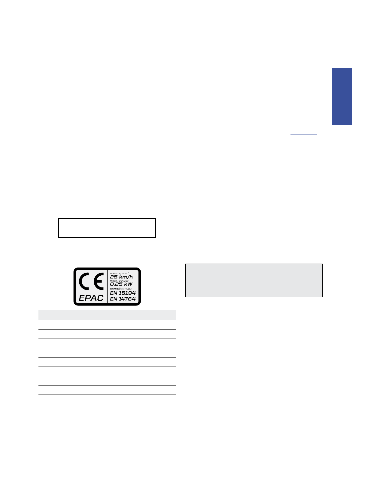
This bike complies with EN 15194. EN14764 Electrically Power Assisted Cycles (EPAC).

Español ITalIaNo NEDERlaNDs FRaNÇaIs DEUTsCH ENGLISH
2
Intended Use
Your E-Series bike has an electric pedal assist drive system. It is not a
moped or motorcycle. In EU countries, it is known legally as an “EPAC”
cycle or Electrically Powered Assisted Cycle.
The drive assist system consists of a drive unit, a battery, a computer
control, and various electronic components (harness wires, sensors, and
switches). Your E-Series bike does share components common with
pedal only bikes.
It is important to know that when the assist system is turned ON, the
drive unit engages to provide power only while you are pedaling. The
amount of power provided by the drive unit depends on your pedaling
force and the assistance mode/level you set with the handlebar control
unit. At anytime, if you stop pedaling, the drive assist will disengage.
In all modes/levels, the drive assist system power reduces progressively
and cuts off as the bike reaches a speed of 25 km/h, (15.5 mph), or
sooner if you stop pedaling. The drive assist re-engages when speed
drops below 25 km/h, (15.5 mph) as long as the pedals are turning.
Whenever the drive assist system is turned OFF, You can pedal the bike
normally. The drive system will not engage.
MAVARO
ASTM CONDITION 2,
General Purpose
Riding
INTENDED:For paved roads, gravel or dirt
roads that are in good condition, and bike
paths.
NOT INTENDED: For off-road or mountain
bike use, or for any kind of jumping.
TRAMOUNT
ASTM CONDTION 3,
Hardtails
INTENDED: for “limited” mountain bike
use, riding only improved trails and surfaces
without jumps or obstacles.
NOT INTENDED: for any jumping, very
aggressive cross-country/mountain bike
riding, racing or stunts. Jumping or riding
over very technical, rough or unimproved
trails (roots, rocks, embankments) can result
in serious damage to the frame or drive
system. Indications of such abuse would
void applicable warranties.
**EXCEPTION: This model must not be
used as a commuter bike until the proper/
required accessories (reflectors, lighting, and
locally required safety devices have been
installed by a professional bike mechanic.
WARNING
**INTENDED USE: This bicycle is intended to be used as a
commuter bicycle. This bike complies with the requirements of
European Standard EN 15194, Electrically Power Assisted Cycles.
The drive assist system is limited to a maximum continuous
power rating of 0,25 kW (250 W) and a maximum speed of
25Km/h, (15.5 mph).
NOT INTENDED: You must not ride this bike in automobile
traffic lanes. This vehicle must only be operated on paved
surfaces that are legally open to commuter pedal bicycles. This
bike is not for mountain biking use, jumping, or racing.
YOU MUST FOLLOW ALL LOCAL LAWS: It is your responsibility
to identify and follow all local laws and regulations (including
fitting your bike with additional equipment) necessary to
comply with local laws. Ask your Cannondale Dealer for more
information about operating an electrically assisted pedal
bicycle in your area.
DO NOT MODIFY THIS BICYCLE/FORK IN ANY WAY FOR ANY
REASON. Doing so can result in severe damage, faulty or
dangerous operating conditions, or violation of local laws.
IMPORTANCE OF PRACTICE & RIDER TRAINING - Before you
ride this bike, practice riding in a safe area free from hazards.
Take time to learn to bike’s controls and performance. Practice
the controls and gain the experience necessary to avoid the
many hazards you will encounter while riding.
DO NOT RIDE “HANDS-OFF - Keep you hands on and the
handlebars when riding the bike. If you remove your hands
from the handlebar while riding, you can lose control of the
bicycle and crash.
UNDERSTAND YOUR BIKE AND ITS INTENDED USE. USING
YOUR BIKE THE WRONG WAY IS DANGEROUS.
Please read your Cannondale Bicycle Owner’s Manual for more
information about Intended Use and Conditions 1-5.
YOU CAN BE YOU SERIOUSLY INJURED, PARALYZED OR KILLED
IF YOU IGNORE THESE WARNINGS.
SAFETY INFORMATION
E-Series Owner’s Manual Supplement - 130374
ESPAÑOL ITALIANO NEDERLANDS FRANÇAIS DEUTSCH ENGLISH
3
Battery & Charger
WARNING
BOSCH INSTRUCTIONS - In addition to this supplement,
you must read and follow the BOSCH battery and charger
instructions. Go to: http://www.cannondale.com/manual_
ebikes/
REPLACEMENT - Only use the battery pack and charger
indicated in the Specifications section of this supplement. Do
not use other batteries or chargers. Do not use the charger to
charge other batteries.
PREVENT DAMAGE - Do not drop the battery or charger. Do
not open or modify the battery or charger. No user serviceable
parts inside.
Keep the battery out of intense sunlight. Keep away from heat.
Heat will damage the battery.
Keep battery away from paper clips, coins, keys, nails, screws or
other small metal items, to prevent shorting exposed battery
contacts. Shorting battery contacts can cause severe burns, fire,
or explosion.
ACCIDENTAL ACTIVIATION - Always remove battery from bike
rack before working on the bicycle or if you transport the bike
by car or plane. Accidental activation of the bicycle drive
system can result in serious injury.
STORAGE & TRANSPORTATION - When the battery is not in
use in the bicycle, its transportation is subject to hazardous
materials regulation. Special packaging and labeling
requirements may exist. Contact local authorities for specific
requirements. Never transport a damaged battery. Insulate
battery contacts before packaging. Package the battery inside
shipping container to prevent damage.
CHARGING - Remove battery from bike before charging. Bring
indoors and allow to reach room temperature before charging.
Make sure charger and A/C outlet are the same voltage.
Locate both charger and battery indoors, in a clean, dry area
with good ventilation to charge. Make sure the area is free from
combustibles to avoid fire from sparks or overheating. Keep
charger ventilation openings unobstructed. Do not cover the
charger.
Disconnect the battery from the charger unit when fully charged.
Do not leave a fully charged battery connected to the charger.
Unplug the charger from the wall outlet when not in use.
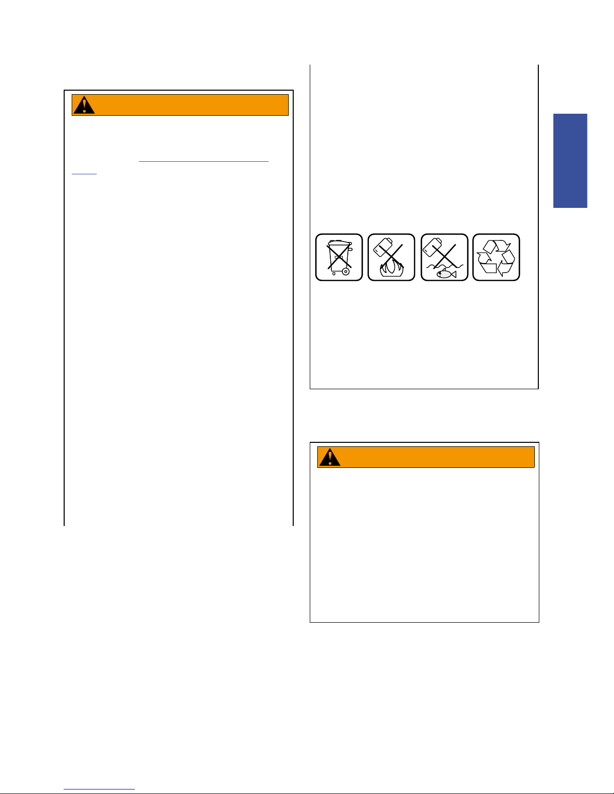
DISPOSAL- Battery pack/charger contain regulated materials
and must be disposed/discarded in accordance with national
and/or local laws. Do not discard the battery/charger into fire,
water or ordinary household waste/garbage. Take to a waste
facility/recycler.
+
+
TRANSPORTATION & SHIPPING - The battery of this bicycle is
subject to transportation regulations for handling hazardous
materials. The battery must be removed before flying and may
be subject to special handling by the carrier.
Failure to observe these warnings can result in electrical fires,
explosion, or severe burns or electrocution.
YOU CAN BE YOU SERIOUSLY INJURED, PARALYZED OR KILLED
IF YOU IGNORE THESE WARNINGS.
Rear Rack & Kickstand
WARNING
Do not sit on the bicycle with the kickstand down. Kickstand
is not designed to support the weight of a person. Make sure
kickstand is up before riding.
Do not overload the rear rack. Make sure the cargo is secured
properly.
RACK MAXIMUM WEIGHT LIMIT: 25Kg, 55lbs
YOU CAN BE YOU SERIOUSLY INJURED, PARALYZED OR KILLED
IF YOU IGNORE THESE WARNINGS.
L2
A2
L1
3
9
10
17,18
9
A8
3
10
17,18
3
BELL
FB
SHFT
RB
10
CHN
CR
CG
KCK
RCS
RD
MAVARO
TRAMOUNT
Español ITalIaNo NEDERlaNDs FRaNÇaIs DEUTsCH ENGLISH
4
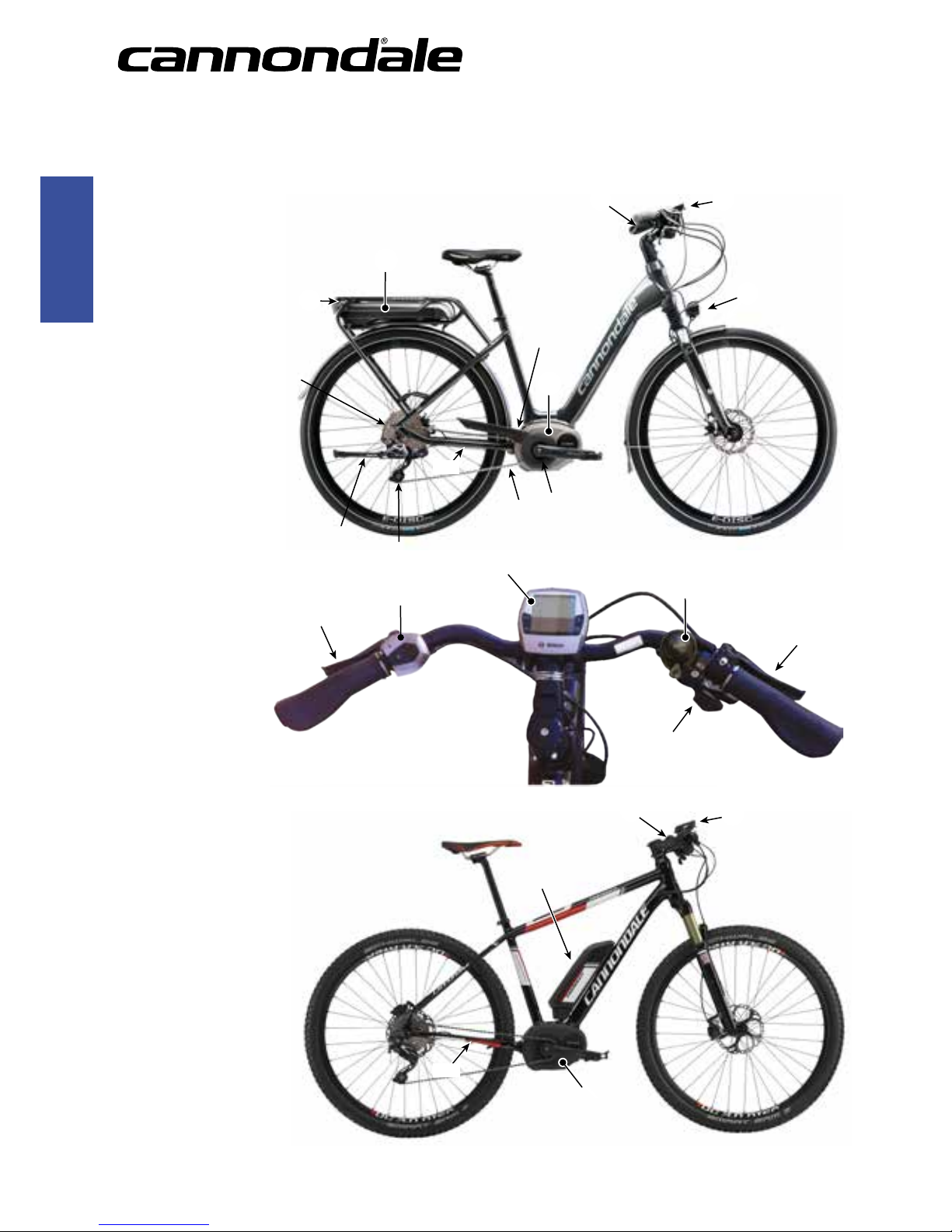
PARTS OF THE E-SERIES BIKE
3 Drive HMI
9 Drive unit
10 Operating unit
17 Speed sensor
18 Spoke magnet of
the speed sensor
A2 Rack-type battery pack
A8 Standard battery pack
L1 Headlight
L2 Taillight
FB - Front Brake
RB - Rear Brake
BELL - Bell
SHFT - Gear Shift
CHN - Drive Chain
CR - Chainring
CG - Chain Guard
KCK - Kick Stand

E-Series Owner’s Manual Supplement - 130374
ESPAÑOL ITALIANO NEDERLANDS FRANÇAIS DEUTSCH ENGLISH
5
OPERATION
Notes on Riding with the
eBike System
When does the eBike Drive Operate?
The eBike drive supports you when riding, as long as you step into
the pedals. Without pedaling, there is no assistance. The motor
output always depends on the amount of your pedaling power.
When applying less pedaling power, the assistance or support will
be lower than when applying a lot of pedaling power. This applies
independent of the assistance Level.
The eBike drive automatically switches off at speeds in excess
of 25 km/h. When the speed falls below 25 km/h, the drive is
automatically available again. An exception applies for the pushassistance function, in which the eBike can be pushed at low speed
without pedaling. The eBike can also be ridden as a normal bicycle
without assistance at any time, by either switching off the eBike
system or setting the assistance level to “OFF”. The same applies
when the battery pack is empty.
Interaction of the eBike System with the Bicycle Gears
The bicycle gears should be used as with a normal bicycle, even
with eBike drive (please observe the operating instructions of your
eBike).
Independent of the type of gearing, it is recommended to briefly
interrupt the pedaling while changing gears. This makes changing
gears easier and reduces the wear of the drive train.
By selecting the right gear, you can increase the speed and range
with the same pedaling effort.
Gathering First Experience
It is recommended to gather first experience with the eBike away
from roads with heavy traffic.
Try out the different assistance levels. As soon as you feel safe, you
can participate in traffic with the eBike as with any other bicycle.
Test the operating range of your eBike under different conditions
before planning longer and more challenging rides.
Factors Affecting Assistance Range
1. Battery Charge Level - A fully charged battery will provided
the greatest range. Before every ride, make sure the battery
is fully charged.
2. Assitance Mode & Support Level - The assistance mode and
support level you select during the ride will affect the operating
range.
3. Temperature & Wind Conditions - Extreme cold or hot
conditions will result in more rapid depletion of the battery’s
energy, reducing available range. Overcoming strong winds
on the cycling route will shorten assistance range since more
battery energy is required. Conversely, a tailwind (wind behind
you) acts to propel the cycle reducing the energy requirement.
4. Rider Weight & Cargo - Adding weight to the bicycle (rider or
cargo) cycle will require the drive unit to work harder, requiring
more battery energy - shorter range. If you carry a backpack
or extra luggage on the rack, more energy will be needed, and
overall range will be reduced.
5. Tire Pressure/Condition- Make sure your tires are in good
shape (e.g. good tread, undamaged) and pressurized properly
according to the tire sidewall markings. Poor tire condition or
Inadequate air pressure will shorten range.
6. Shifting Gears & Braking - You should shift gears similarly to
a normal pedaling bicycle. Efficient gear changes will result in
greatest available range. Maintaining a uniform speed and
effective braking will help you maximize the energy stored in
the battery.
7. Accelerating From Stopped - The drive system utilizes more
battery energy during it initial acceleration. Therefore, a
commute with frequent starting and stopping will consume
more energy, shortening range. You can extend your range by
carefully managing your speed throughout the trip to avoid
unnecessary starts and stops.
8. Drive Chain Condition - Be sure to keep the chain clean and
well lubricated. Have the chain replaced with a new one.
9. Pedaling - Pedaling steadily with moderate effort with the
drive unit will result in the greatest range. While all that is
requirted to engage the assistance is a turning pedal, you’ll
want to contribute especially on uphill or rough terrain. If you
rely solely on the drive unit, the range will be much shorter.
Español ITalIaNo NEDERlaNDs FRaNÇaIs DEUTsCH ENGLISH
6
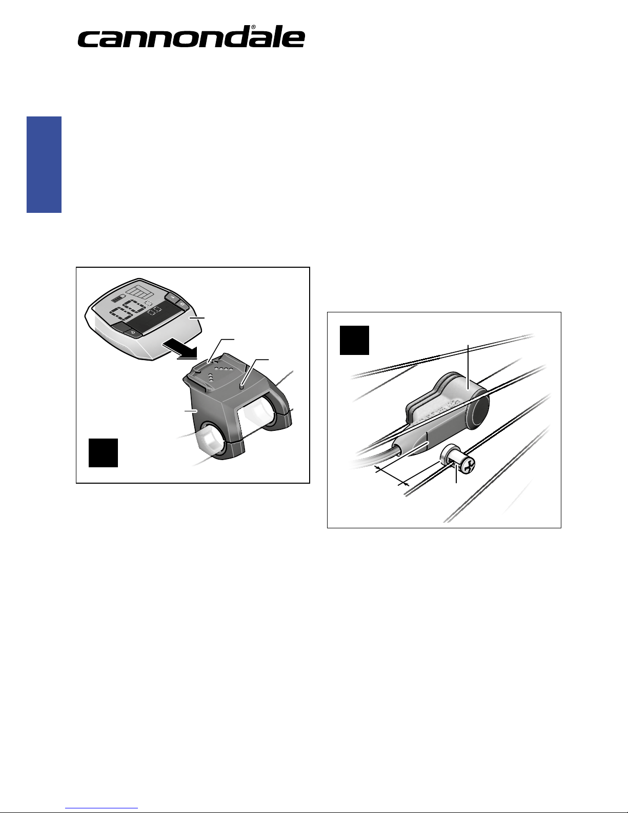
Inserting and Removing the HMI
(see figure A)
To insert the HMI 3, slide it from the front into the holder 4.
To remove the HMI 3, press the lock latch 15 and slide the HMI
toward the front out of the holder 4.
■ Remove the HMI when you park the eBike.
It is possible to secure the HMI against removal in the holder. To do
so, remove the holder 4 from the handlebars. Put the HMI in the
holder. Screw the locking screw 16 (thread M3, 8mm long) from
below into the thread provided in the holder. Mount the holder back
onto the handlebars.
ECO
KM/H
Reichweite
KM/H
RESET
KM /H
M
/H
4
3
15
16
A
Checking the Speed Sensor
(seefigureB)
The speed sensor 17 and its spoke magnet 18 must be mounted in
such a manner that the spoke magnet, after a turn of the wheel,
moves past the speed sensor with a clearance of at least 5mm, yet
no more than 17mm.
Note: If the clearance between speed sensor 17 and spoke magnet
18 is too small or too large, or if the speed sensor 17 is not properly
connected, the speed indication f will fail, and the eBike drive will
operate in emergency mode.
In this case, loosen the screw of the spoke magnet 18 and fas-ten
the spoke magnet to the spoke in such a manner that it runs past
the mark of the speed sensor at the correct clearance. When the
speed is still not being indicated in the speed indication f after this,
please refer to an authorised bicycle dealer.
B
17
18
5
–
17 mm
13
11
10
12
TURBO
SPORT
TOUR
ECO
OFF
MPH
KM/H
Reichweite
AMM
PMWH
MIN
MPH
KM/H
d
b
c
a
f
g
e
TURBO
SPORT
TOUR
MPH
KM/H
Reichweite
AMM
PMWH
MIN
MPH
KM /H
RESET
KM/H
/H
3
2
1
6
5
4
7 8
14
E-Series Owner’s Manual Supplement - 130374
ESPAÑOL ITALIANO NEDERLANDS FRANÇAIS DEUTSCH ENGLISH
7
Switching the eBike System On/Off
Options for switching on the eBike system:
– If the HMI is already switched on when inserted into the holder,
then the eBike system will be switched on automatically.
– When the HMI and the battery pack are inserted, briefly press
the On/Off button 5 of the HMI once.
– When the HMI is inserted, press the On/Off button of the
battery pack (see battery pack operating instructions).
The drive is activated as soon as you step into the pedals (except
when in push assistance mode, see “Switching the Push/Start Aid
On/Off” . The motor output depends on the settings of the HMI.
As soon as you stop pedaling when in normal operation, or as soon
as you have reached a speed of 25/45km/h, the assistance from the
eBike drive is switched off. The drive is automatically reactivated as
soon you start pedaling again and the speed is below 25/45km/h.
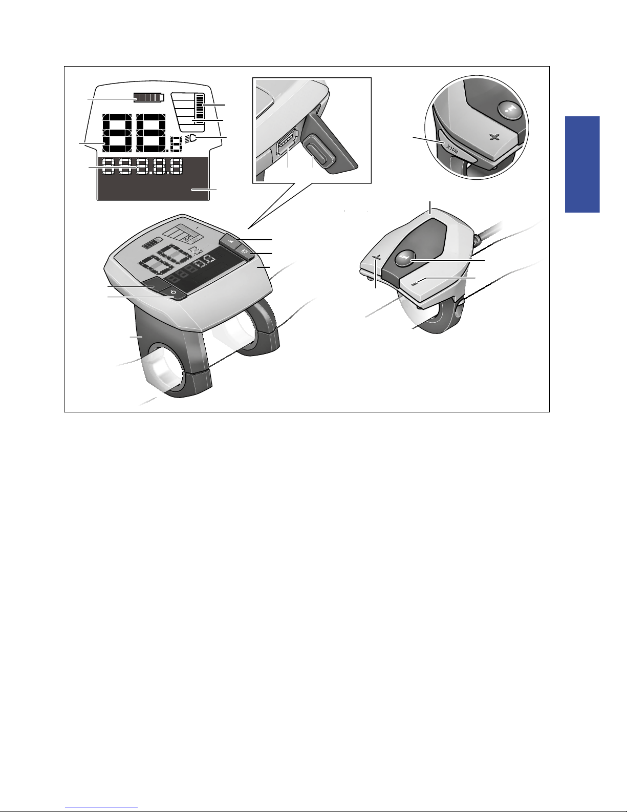
1. Display-function button “i”
2. Illumination button
3. Drive HMI
4. Holder for drive HMI
5. Drive HMI On/Off button
6. “RESET” button
7. USB port
8. Protective cap of USB port
9. Drive unit
10. Operating unit
11. Display-function button “i” on the operating
unit
12 . Reduce value/scroll down button “ –”
13 . Increase value/scroll up button “+”
14. Push-assistance button “WALK”
Indication Elements, Drive HMI
a. Motor-output indicator
b. Assistance-level indicator
c. Text indication
d. Value indication
e. Speed indication
f. Battery charge-control indicator
 Loading...