

Cannondale 2012 IQ300 Setup And Owners Manual
THANK YOU FOR PURCHASING A CANNONDALE
Congratulations on your purchase of a Cannondale IQ Series computer.
Proper setup and operation will greatly enhance this product’s usefulness and your
enjoyment.
Please follow all Warnings and read all sections of this manual carefully and become fully
familiar with its operation before using it.
YOUR CANNONDALE RETAILER
Along with this manual, your key source of information and assistance is the shop where
you purchased this product. Your local Authorized Cannondale Retailer is your primary
contact to discuss service and adjustment to this product, instruction in its use, and any
warranty questions.
To nd an Authorized Cannondale Retailer closest to you, call 1800BIKEUSA. Or you can
use our dealer locator at our website www.cannondale.com.
IMPORTANT INFORMATION FOR ALL CANNONDALE CYCLING COMPUTERS
WARNINGS
WIRELESS COMPUTER MODELS (IQ200, IQ300, and IQ400) - People with medical/
implanted electronic equipment or devices such as heart pacemakers, EKG equipment,
etc. must not use wireless cycle computers due to possible risk of interference with the
medical devices.
EXERCISE - Adults with health problems (such as heart disease, diabetes or obesity) or
those at high risk, men over age 40 and women over age 50 or pregnant should talk
with their doctor before starting an exercise program.
INTENDED USE: For bicycle use only. Not for use on any motorized vehicle.
OPERATE COMPUTER ONLY WHEN NOT RIDING: Failure to pay attention to the road,
trail, trac or your surroundings could result in an accident, with risk of serious injury,
paralysis or death. You must focus on riding, not your computer. Learn computer operations, and do all possible computer operations when not riding. For any operations you
choose to perform while riding, choose a time and place where this distraction has less
risk.
MAKE SURE ALL COMPUTER PARTS ARE INSTALLED PROPERLY: The computer
must not interfere with the bicycle controls and your ability to use them. Mount the
computer according to the directions in this instruction manual. See your Authorized
Cannondale Retailer if you have any trouble installing or maintaining your computer.
CHECK FOR DAMAGE REGULARLY: Regularly check the position, alignment, and
condition of the spoke magnet, wireless sensor, cadence sensor, sensor and sensor wire
to make sure they are secure, aligned and in good condition. Make sure nothing is loose
and there are no worn or damaged parts.
BATTERIES: Use only battery size and type specied on the unit. Do not leave any
batteries in reach of children, and dispose of them correctly. If a battery is swallowed,
consult a doctor immediately.
NOT A TOY: Keep this computer and associated parts including the battery away from
children. Small parts could be swallowed.
YOU CAN BE SEVERELY INJURED, PARALYZED OR KILLED IN AN ACCIDENT IF YOU
IGNORE THESE WARNINGS.
NOTICE
■ This product is rain-proof only. Do not submerge or power wash.
■ Do not disassemble the unit.
■ Mount the computer according to the directions in this instruction manual.
■ Avoid direct impact to the computer unit.
■ Avoid using the computer unit in or near strong electromagnetic elds such as
high-voltage power lines or other transmitters.
■ Clean the unit with a mild detergent and a soft dry cloth. Never use any kind of
solvent or alcohol.
■ To prevent damage caused by battery leakage, remove the batteries before storage
or long period of non-use. Do not reverse battery installation. Observe positive (+)
and negative (-) markings.
■ WIRELESS MODELS (IQ200,IQ300, IQ400) Wireless computer uses an analog
wireless signal. It is not digitally coded but uses technology to lower the chance of
interference with circuitry used in other electronic devices such as lights, phones ,
computers, etc.
2012 IQ300 Computer
Setup and Owners Manual - 11/11
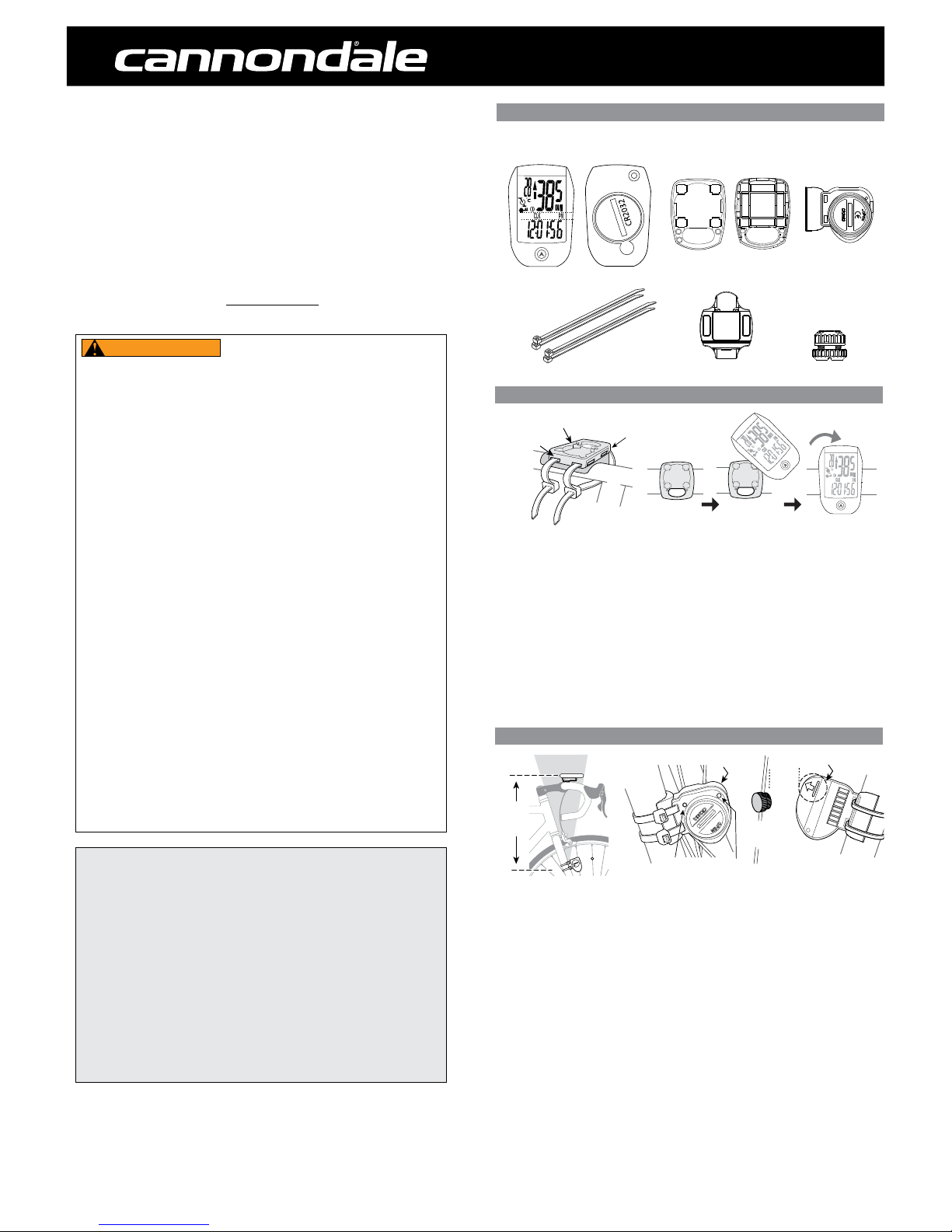
COMPUTER PARTS
COMPUTER INSTALLATION
The computer unit can be mounted on a bicycle handlebar or stem.
1. To mount the bracket, insert two nylon ties through the mounting bracket slots.
(a) - handlebar slots, (b) stem slots
2. Insert the rubber pad into back of mount bracket for handlebar or stem by aligning
slots in the back of the mount with the pad.
3. Position the pad/bracket onto the handlebar or stem and tighten both nylon ties
securely. Carefully snip tie ends 1-2mm from tie head.
To mount the computer onto the bracket, position it into the bracket at a 45 degree angle,
hold down and rotate the computer unit clockwise to lock it in place. To remove it, rotate
the computer counter-clockwise and lift it o.
NYLON TIES
MOUNTING BRACKET
HANDLEBAR
a
b
touch
touch
SENSOR INSTALLATION
Check the following components before installation:
1. Position the sensor on the front of the right fork leg within 60 cm of the computer. The
battery door must face out with the tear drop shape pointing down shown.
2. Pass the two cable ties through the sensor mounting holes and loosely mount the fork
sensor body to the left fork blade (do not fully tighten the cable ties at this point).
Loosely install the sensor magnet to one of the spokes of the front wheel. Adjust the
position of the magnet and sensor together so that the magnet is aligned with the line on
the bottom edge of the sensor and 1-2 mm separates the two parts and tighten both parts
in place.
Secure the sensor to the fork leg with two nylon ties.
3. Install the magnet onto a spoke so the magnet will pass over the sensor in the pickup zone
when the wheel is rotated.
4. Set the sensor-to-magnet gap by tilting the sensor toward or away from pickup zone. The
maximum distance between the speed sensor and magnet on the spoke is 5 mm.
5. When set, draw the nylon ties securely. Carefully snip the tie ends 1-2mm from tie head.
IQ300 COMPUTER UNIT
(back)
(front)
WIRELESS SENSOR
SPOKE MAGNET
NYLON TIES (X4)
MOUNTING PAD
MOUNTING BRACKET
(back)(front)
touch
MAX. 30
o
MAX.
60 cm
5 mm
MAX.
5 mm
SPOKE
MAGNET
PICK-UP ZONE
WIRELESS SENSOR
SENSOR
PROGRAMMING BUTTON
SENSOR
INDICATOR LED

2012 IQ300 Computer
Setup and Owners Manual - 11/11
NOTE: This computer can record information for 2 bikes with dierent wheel sizes. This
allows you to use 1 computer for 2 bikes. Shortly after the wheel rotates, the computer
automatically knows which bike is being used then provides accurate information for
speed and mileage. A mounting kit for a 2nd bike is sold separately. The following steps
only need to be done once.
To start programming:
1. Press FUNCTION until “ODO” displays.
2. Press and hold SET for >3 seconds to begin programming.
3. Press SET to change to “KM/H” or “M/H”
To program the computer for bike #1:
4. Determine your Tire Size then nd the corresponding L (mm) in the chart below.
5. Press SET to select bike 1 “
”
6. Press FUNCTION to move the cursor to the rst eld.
7. Press SET to change the 1st digit of 4 numbers for the L (mm).
Repeat steps 6 and 7 until the proper L (mm) is entered.
If you will use this computer for 2 bikes, continue to step 8.
If you will use it for only 1 bike, continue to step 10.
To program the computer for bike #2:
8. Determine your Tire Size then nd the corresponding L (mm) in the chart below.
9. Press FUNCTION to select bike 2 “ ”
Repeat steps 6 and 7 until the proper L (mm) is entered.
10. Press and hold FUNCTION for 3 seconds to exit programming.
SETTING THE CLOCK CLK
1. Press FUNCTION until the “CLK” function shows.
2. Press and hold SET for >3 seconds to begin programming.
3. Press SET to change to “12H” or “24H” hour mode.
4. Press the FUNCTION to move the cursor to the hour eld
5. Press SET hour.
6. Repeat steps 4 and 5 to set Minutes and Seconds.
7. Press and hold the FUNCTION button for 3 seconds to exit programming.
GENERAL NOTES FOR PROGRAMMING ALL FUNCTIONS:
• Press and hold SET for 3 seconds to begin programming a function.
• Press the SET to change the value of a selected eld. Press/hold SET to change
value rapidly.
• Press the FUNCTION button to move the cursor to the next eld.
• Press and hold the FUNCTION button for 3 seconds to exit programming.
SETTING THE WHEEL SIZE
L (mm)
Tire Size L (mm) Tire Size L (mm)
24 X 1.75 1890 27 X 1-3/8 2169
24 X 2.00 1925 650 X 20C 1938
24 X 2.125 1965 650 X 23C 1944
26 X 7/8 1920 650 X 35A 2090
26 X 1(59) 1913 650 X 38A 2125
26 X 1(65) 1952 650 X 38B 2105
26 X 1.25 1953 700 X 18C 2070
Tire Size L (mm) 26 X 1-1/8 1970 700 X 19C 2080
14 X 1.50 1020 26 X 1-3/8 2068 700 X 20C 2086
14 x 1.75 1055 26 X 1-1/2 2100 700 X 23C 2096
16 X 1.50 1185 26 X 1.40 2005 700 X 25C 2105
16 X 1.75 1195 26 X 1.50 2010 700 X 28C 2136
18 X 1.50 1340 26 X 1.75 2023 700 X 30C 2146
18 X 1.75 1350 26 X 1.95 2050 700 X 32C 2155
20 X 1.75 1515 26 X 2.00 2055 700C Tubular 2130
20 X 1-3/8 1615 26 X 2.10 2068 700 X 35C 2168
22 X 1-3/8 1770 26 X 2.125 2070 700 X 38C 2180
22 X 1-1/2 1785 26 X 2.35 2083 700 X 40C 2200
24 X 1 1753 26 X 3.00 2170 29 X 2.1 2288
24 X 3/4 Tubular 1785 27 X 1 2145 29 X 2.3 2326
24 x 1-1/8 1795 27 X 1-1/8 2155
24 X 1-1/4 1905 27 X 1-1/4 2161
To begin using the computer, simply press the FUNCTION button. Following installation,
the computer is activated automatically by a rotating wheel.
There are 2 power saving modes - 50% savings if no movement after 5 minutes, 100%
power savings after 30 minutes.
Press the SET button to exit the power saving modes prior to using the computer.
Press the FUNCTION button, to switch the computer through the following functions:
“CLK” – Clock feature, in 12/24 hr format
“TM” – Time ridden for 1 ride
“AVS ” – Average speed for 1 ride
“MXS” – Maximum speed for 1 ride
“DST” - Distance ridden for 1 ride
“ODO” – Total miles ridden for all rides
“KCAL ” – Calories burned (estimate) for 1 ride
“DAILY” -- DIstance ridden in the past 24 hours
“ODO 1” -- Total miles for all rides, bike 1 “ ”
“ODO 2” -- Total miles for all rides, bike 2 “
”
To turn on the backlight, press and release the SET button. The backlight will stay
on for three (3) seconds.
“TM, AVS, MXS, DST, and KCAL “ are recorded automatically as soon as the wheel moves.
Recording stops if the wheel stops. To clear this information, press and hold the SET
button in the “TM” mode.
MAIN DISPLAY AND FUNCTIONS
C
R
2
0
3
2
touch
SET Button
(back of unit)
**This button also,
activates the display
backlighting.
CURRENT SPEED
SPEED SCALE
MODE
FUNCTIONS DISPLAY
FUNCTION Button
SUB-DISPLAY
TEMPERATURE
MOTION SIGNAL
BIKE “I or BIKE “II”
SLEEP MODE
 Loading...