

Cannondale E440, C440, X440, 2002 E440, 2002 C440 Owner's Manual
...
P/N 951 - 5002274
Before you operate the vehicle. . . .
• READ and UNDERSTAND this manual. It contains information important to
your safety.
• Familiarize yourself with all vehicle controls and their proper operation.
• Perform the Pre-Ride Inspection found in this manual.
• Wear appropriate protective gear - approved full faced helmet, eye protection,
gloves, boots, long-sleeve shirt, and pants. Consider specially designed
protective off-road vehicle riding apparel.
• Safety
• Operation
• Maintenance
2002
MOTORCYCLE OWNER’S MANUAL
(E440, C440, X440)
© 2002 Cannondale Corporation - All Rights Reserved
2
Safety Alerts.fm
SAFETY ALERTS
• FAILURE TO FOLLOW THE WARNINGS CONTAINED IN THIS MANUAL CAN RESULT IN SERIOUS
INJURY OR DEATH.
• Keep this manual in a safe place.
WHAT IS THE SAFETY ALERT SYMBOL ?
• Pay special attention to all messages preceded by the Safety Alert Symbol.
It means: ATTENTION! BECOME ALERT! YOUR SAFETY IS INVOLVED.
CAUTION
Indicates a potential hazard that could result in vehicle damage if instructions are not followed.
NOTE :
Provides helpful info rmat ion intended to make maintenance easier or the instructions presented clearer.
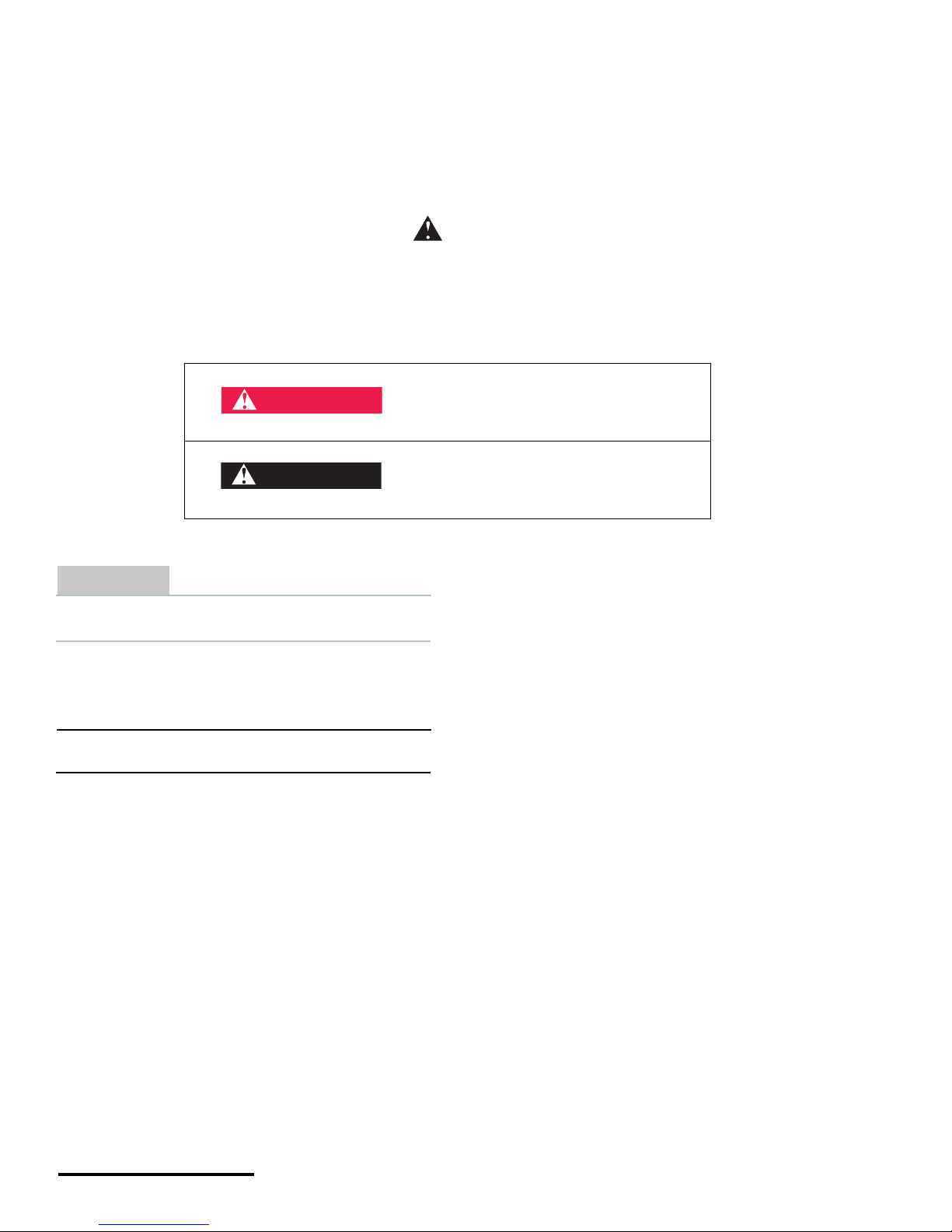
Indicates that severe personal injury or
death WILL result if instructions are not
followed.
Indicates a potential hazard that COULD
result in serious injury or death.
DANGER
WARNING
3
Printed : 1/9/02
3
GENERAL PRECAUTIONS
YOU must always exercise good judgement when
assessing your abilities to perform the work
described in this manual.
• Make sure you are familiar with basic safety
practices before performing any work on the
vehicle.
• Always work in a well-ventilated area. Car bon
monoxide gas (a by-product of combustion
engines) is poisonous; you can be seriously
injured or even killed if you breathe it.
• Do not service the vehicle with the engine
running unless otherwise stated in a procedure.
• You can be seriously injured by moving parts.
Always keep your hands, fingers, and clothing
away from moving parts.
• Avoid hot components (e.g., engine, exhaust
system, coolant system, brake discs , etc.); they
can burn you. Allow all components to cool
completely before touching or handling them.
• Always place the vehicle on a level surface or
proper stand when performing any work to help
eliminate the chance of the vehicle rolling away
or becoming unstable while you work.
• Make sure you have the skills and tools
necessary before performing any procedure.
• Make sure you are wearing the appropriate
protective clothing when servicing the vehicle
(e.g., safety gla sses or a face shield, protect ive
gloves.
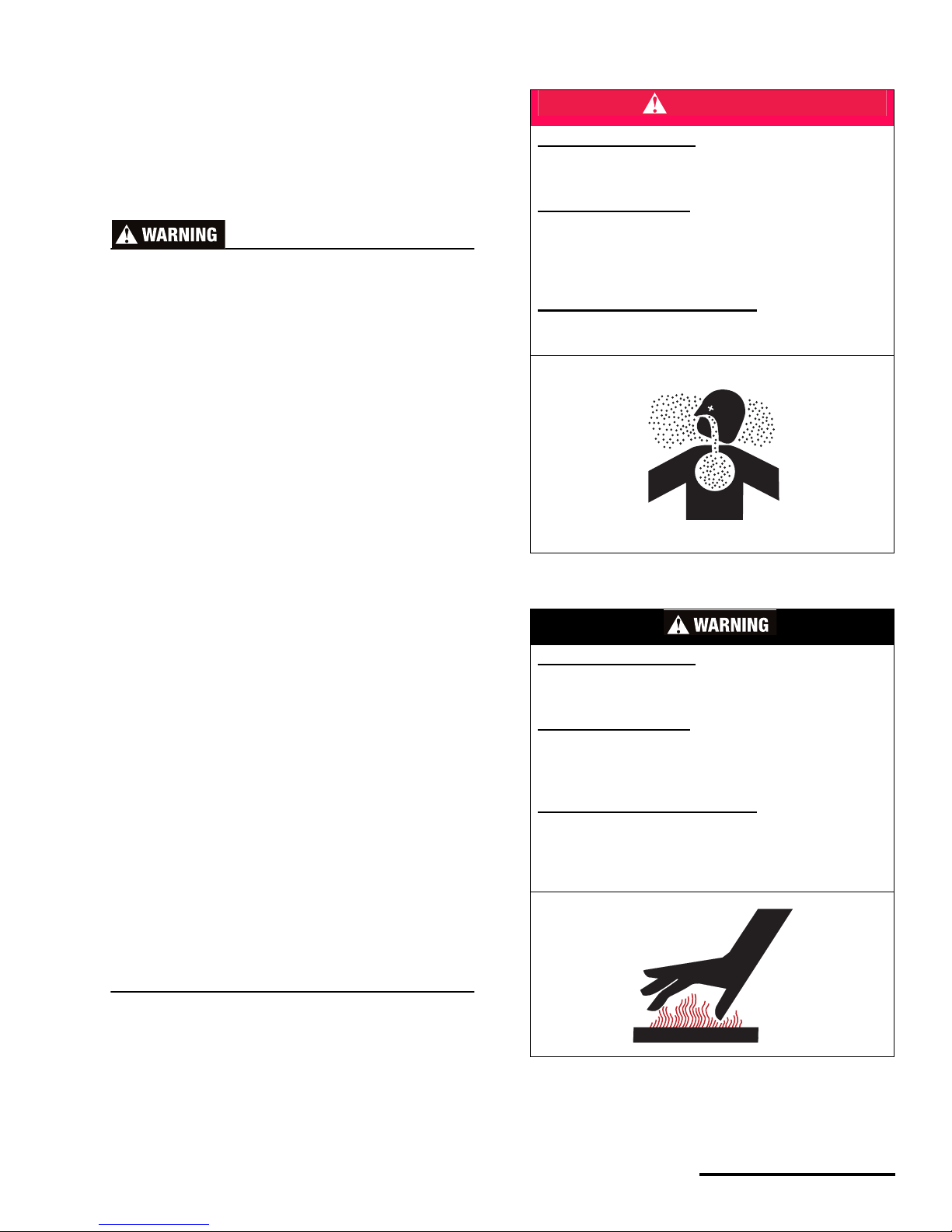
DANGER
POTENTIAL HAZARD
Running the engine indoors.
Breathing exhaust gases
WHAT CAN HAPPEN
Running the engine indoors will expose you to
dangerous exhaust gases. Breathing carbon
monoxide gas leads to poisoning, asphyxiation, and
death. This will happen rapidly and without notice.
HOW TO AVOID THE HAZARD
Never operate the vehicle indoors even for brief
periods of time.
POTENTIAL HAZARD
Hot components (e.g., engine, radiator, hoses,
bulbs, exhaust, brakes)
WHAT CAN HAPPEN
The engine and other vehicle systems operate at
extremely high temperatures. Contact can produce
severe burns.
HOW TO AVOID THE HAZARD
Wait for the engine and vehicle systems to cool
completely before starting any work. If the engine
must be running, work carefully and avoid hot
surfaces.
© 2002 Cannondale Corporation - All Rights Reserved
4
Safety Alerts.fm
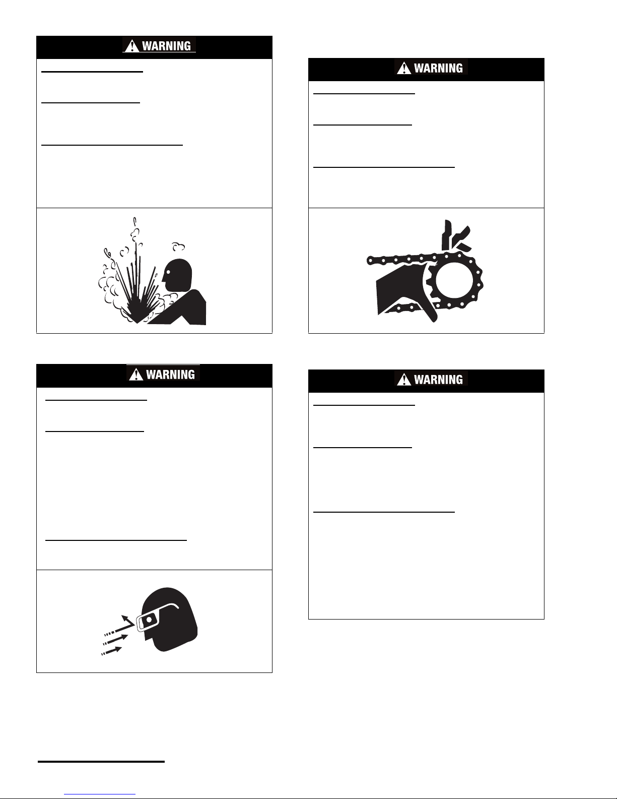
POTENTIAL HAZARD
Improper care when handling fuel.
WHAT CAN HAPPEN
Fuel is highly flammable, spilling it can cause a fire
or explosion.
HOW TO AVOID THE HAZARD
Be sure the fuel cap is closed securely.
Work in a well-ventilated area which is free of
sources that could ignite any spilled fuel
accidentally (e.g. cigarettes, welders, torches,
grinders, electric shop tools, etc.)
POTENTIAL HAZARD
Blindness, eye injury
WHAT CAN HAPPEN
Anytime you work on the vehicle there is a
potential that an accident involving a foreign
object, vehicle component part, fluid, tool, or other
maintenance related item can result in severe
injury to your eyes. For example, when cleaning
the oil filters, objects propelled by compressed air
can strike your eyes and cause serious injury or
blindness.
HOW TO AVOID THE HAZARD
Always wear safety glasses when working on the
vehicle.
POTENTIAL HAZARD
Losing a finger , h and or limb or entanglement
WHAT CAN HAPPEN
Moving parts can catch your clothing, fingers or
hand resulting in severe injury.
HOW TO AVOID THE HAZARD
Never perform maintenance procedures with the
engine running unless directed otherwise in a
procedure.
POTENTIAL HAZARD
Vehicle fluids (e.g., engine oil, transmission oil,
brake fluid, coolant)
WHAT CAN HAPPEN
The fluids in your vehic le are hazar dous subs tances .
Contact with your skin or eyes you can result in
serious injury or irritation.
If swallowe d, death can result
HOW TO AVOID THE HAZARD
Wear hand protection and safety glasses when
working with vehic le fluid s.
If you touch a fluid, wash it off immediately with
soap and water.
Clean clothes or rags contaminated with engine oil.
If swallowed seek immediate medical attention.
KEEP ALL VEHICLE FLUIDS AWAY FROM
CHILDREN AND ANIMALS.

5
Printed : 1/9/02
5
CONTENTS
SAFETY ALERTS . . . . . . . . . . . . . . . . . 2
CONTENTS . . . . . . . . . . . . . . . . . . . . . . 5
IMPORTANT INFORMATION . . . . . . . . 6
About this manual . . . . . . . . . . . . . . . . . . . . . . . 6
How to use this manual. . . . . . . . . . . . . . . . . . . 6
Experienced riders only. . . . . . . . . . . . . . . . . . . 7
Exercise good judgement . . . . . . . . . . . . . . . . . 7
Modifications . . . . . . . . . . . . . . . . . . . . . . . . . . . 7
No passengers . . . . . . . . . . . . . . . . . . . . . . . . . 7
Aluminum chassis components. . . . . . . . . . . . . 8
VEHICLE LABELING . . . . . . . . . . . . . 10
MACHINE IDENTIFICATION. . . . . . . . 12
Vehicle Identification Number (VIN) . . . . . . . . 12
Engine Serial Number. . . . . . . . . . . . . . . . . . . 12
PARTS & CONTROLS . . . . . . . . . . . . 13
Engine start button . . . . . . . . . . . . . . . . . . . . . 13
Engine stop button . . . . . . . . . . . . . . . . . . . . . 13
Lighting switch. . . . . . . . . . . . . . . . . . . . . . . . . 14
Headlight. . . . . . . . . . . . . . . . . . . . . . . . . . . . . 15
Taillight . . . . . . . . . . . . . . . . . . . . . . . . . . . . . . 15
Fuses . . . . . . . . . . . . . . . . . . . . . . . . . . . . . . . 16
Optional lighting . . . . . . . . . . . . . . . . . . . . . . . 16
Multi-function ride computer . . . . . . . . . . . . . . 17
Clutch lever . . . . . . . . . . . . . . . . . . . . . . . . . . . 17
Shift lever . . . . . . . . . . . . . . . . . . . . . . . . . . . . 17
Throttle grip. . . . . . . . . . . . . . . . . . . . . . . . . . . 18
Front brake lever . . . . . . . . . . . . . . . . . . . . . . . 19
Footpegs . . . . . . . . . . . . . . . . . . . . . . . . . . . . . 20
Rear brake pedal. . . . . . . . . . . . . . . . . . . . . . . 20
Side stand or kickstand. . . . . . . . . . . . . . . . . . 21
Handguards. . . . . . . . . . . . . . . . . . . . . . . . . . . 22
Fuel cap . . . . . . . . . . . . . . . . . . . . . . . . . . . . . 23
FLUIDS . . . . . . . . . . . . . . . . . . . . . . . . 24
Fuel . . . . . . . . . . . . . . . . . . . . . . . . . . . . . . . . . 24
Brake fluid . . . . . . . . . . . . . . . . . . . . . . . . . . . . 25
Front brake . . . . . . . . . . . . . . . . . . . . . . . . . . . 25
Rear brake . . . . . . . . . . . . . . . . . . . . . . . . . . . 26
Engine oil . . . . . . . . . . . . . . . . . . . . . . . . . . . . 27
Transmission oil . . . . . . . . . . . . . . . . . . . . . . . 34
Coolant . . . . . . . . . . . . . . . . . . . . . . . . . . . . . . 37
Hydraulic clutch oil . . . . . . . . . . . . . . . . . . . . . 39
PRE-RIDE INSPECTION. . . . . . . . . . . 41
Pre-ride checklist. . . . . . . . . . . . . . . . . . . . . . . 41
OPERATION . . . . . . . . . . . . . . . . . . . . 42
Cold starting . . . . . . . . . . . . . . . . . . . . . . . . . . 42
Starting a warm engine . . . . . . . . . . . . . . . . . .42
Jump starting . . . . . . . . . . . . . . . . . . . . . . . . . . 42
Shifting gears . . . . . . . . . . . . . . . . . . . . . . . . . . 43
Braking. . . . . . . . . . . . . . . . . . . . . . . . . . . . . . .43
Post ride checks. . . . . . . . . . . . . . . . . . . . . . . .43
Break-In . . . . . . . . . . . . . . . . . . . . . . . . . . . . . .44
MAINTENANCE SCHEDULE. . . . . . . 45
Maintenance record. . . . . . . . . . . . . . . . . . . . .47
MAINTENANCE & ADJUSTMENT . . 48
Seat . . . . . . . . . . . . . . . . . . . . . . . . . . . . . . . . . 48
Fuel . . . . . . . . . . . . . . . . . . . . . . . . . . . . . . . . .50
Brakes . . . . . . . . . . . . . . . . . . . . . . . . . . . . . . .55
Clutch. . . . . . . . . . . . . . . . . . . . . . . . . . . . . . . .59
Drive. . . . . . . . . . . . . . . . . . . . . . . . . . . . . . . . . 60
Engine Management System. . . . . . . . . . . . . .66
Electrical. . . . . . . . . . . . . . . . . . . . . . . . . . . . . .68
Air. . . . . . . . . . . . . . . . . . . . . . . . . . . . . . . . . . . 75
Suspension . . . . . . . . . . . . . . . . . . . . . . . . . . . 78
Making Damping adjustments . . . . . . . . . . . . . 78
Wheels. . . . . . . . . . . . . . . . . . . . . . . . . . . . . . .90
Wheel bearing inspection . . . . . . . . . . . . . .90
Tires . . . . . . . . . . . . . . . . . . . . . . . . . . . . . . . . .91
Steering . . . . . . . . . . . . . . . . . . . . . . . . . . . . . . 93
Cleaning. . . . . . . . . . . . . . . . . . . . . . . . . . . . . .95
Storage. . . . . . . . . . . . . . . . . . . . . . . . . . . . . . .97
Torque table. . . . . . . . . . . . . . . . . . . . . . . . . . .98
2002 MODEL SPECIFICATIONS. . . . 99
Engine . . . . . . . . . . . . . . . . . . . . . . . . . . . . . . .99
Chassis . . . . . . . . . . . . . . . . . . . . . . . . . . . . .100
Suspension . . . . . . . . . . . . . . . . . . . . . . . . . . 101

© 2001 Cannondale Corporation - All Rights Reserved
6
Important Information.fm
IMPORTANT INFORMATION
ABOUT THIS MANUAL
The purpose of this manual is to provide the owner
with important safety, service, maintenance, and
tuning information , and shou ld be thor ou ghl y read
before operating or working on the vehicle.
This manual is divided into sections which contain
easy-to-follow procedures which are reasonably
straight-forward. Anyone with the mechanical ability
and the proper tools should be able to perform them.
Each procedure is ac c ompanied by illustrations and
photos to aid in proper vehicle operation, basic
maintenance, tuning, etc.
• Read and understand the entire procedure
before performing any work. If you are
unfamiliar with or doubt your own abilities to
complete a procedure as des cribed, have an
authorized Cannondale Motorsports Dealer
service your vehicle.
Please keep your Owner's Manual in a safe and
convenient place, and consider it an integral part of
your vehicle.
For detailed servici ng info rmati on re fer to the
Service Manual for your vehicle or contact an
authorized Cannondale Motorsports Dealer for a list
of available publications. If this manual is lost or
damaged, contact an authorized Cannondale
Motorsports Dealer for a replacement.
HOW TO USE THIS MANUAL
• This manual is broken down in headings,
numbered steps [which may contain
WARNING(S), CAUTION(S), and/or NOTE(S)],
and illustrations or line art.
• Headings and numbered steps should be
followed in the order in which they are
presented. The explanations given in the
numbered steps are intended t o be used as a
guide for a technician needing additional
information.
• Illustrations and line art are used to identify
parts of the vehicle included in the procedure
to eliminate any possible confusion and to
support the numbered steps.
LIMITATIONS
All information, illustrations, and specifications in
this manual are based on the latest product
information available at the time of publication.
Cannondale Corporation reserves the right to make
changes at any time, without notice.
This vehicle has U.S. and International patents
pending.

7
Printed : 1/9/02
7
EXPERIENCED RIDERS ONLY
• This vehicle is not for beginners.
All Cannondale motorspor ts products are
designed for use by trained and experienced riders
only . A ll are very hi gh perf ormance , compe tition sp ort
machines and sh oul d o nly be operated by licens ed
competition riders in excellent physical condition,
who are well-trained and experienced in the
operation of high performance competition vehicles.
EXERCISE GOOD JUDGEMENT
There is always a ri sk i nvolved when riding a
vehicle; however, making sure you and the vehicle
are in the best condition pos s ible will en sure a great
riding experience. Use sound judgement when riding.
Never ride under the influence of alcohol,
medication, or drugs. Doing so will greatly reduce
your ability to properly operate this vehicle and could
lead to an accident, injury, and/or death. If you are
taking medications prescribed by your doctor, consult
him/her before ridin g.
MODIFICATIONS
We recommend that you do not substitute parts,
change or modify your vehicle. Such changes could
seriously impair your vehicle’s handling, stability , and
braking, making it unsafe to ride and causing serious
injury and/or vehicle damage.
NO PASSENGERS
Do not overload this vehicle or carry passengers.
Doing so could seriously impair your vehicle’s
handling, stability, and braking, making it unsafe to
ride which could result in damage to the vehicle or
serious injury or death to the operator and/or
passenger.
© 2001 Cannondale Corporation - All Rights Reserved
8
Important Information.fm
ALUMINUM CHASSIS
COMPONENTS
The aluminum chassis components of your vehicle
have a finite, limited useful life. The length of that life
varies depending on the material used in their
manufacture, the amount of use they are subjected
to and the care they receive while in service. Regular
inspection by a Cannondale Motorsp or ts Deal er i s
important.
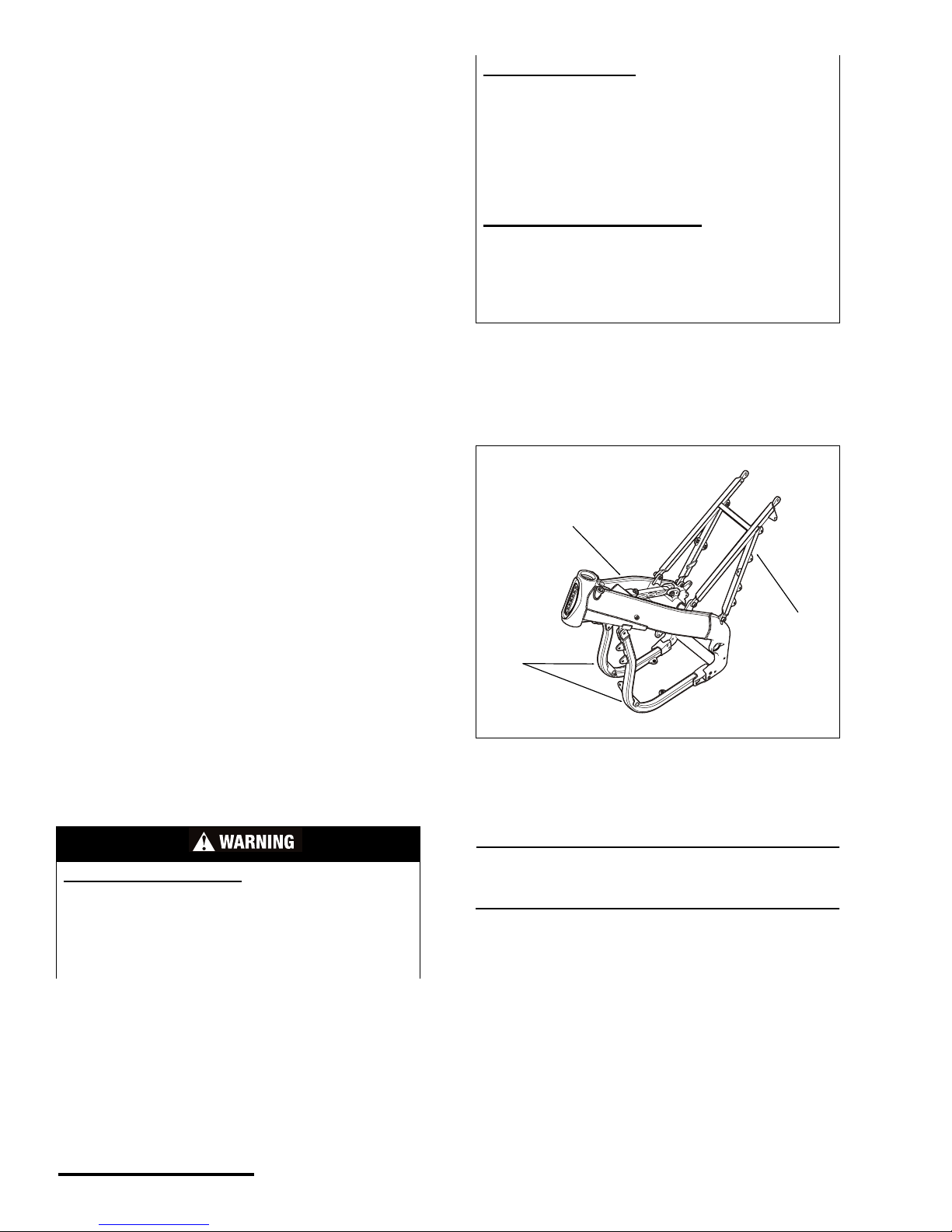
• Frame - a main support structure for the
engine, various components, and rider.
• Subframe - adds structural support.
• Swingarm - a suspension component
Use in competitive events, hard and aggressive
riding, riding on severe terrain, ridi ng in sev er e
climates and riding fast can dramatically shorten the
life of the aluminum (frame) components. Any one
and/or a combination of th ese conditions may result
in an unpredictable failure.
We recommend that you carefully inspect your
vehicle’s chassis components for crac king, bending,
deep scratches and/or other damage before e very
ride.
If you have crashed or rolled your vehicle, there
could be damage hidden from your view. DO NOT
ride a vehicle with any crack, even a small one. It
must be carefully inspected by an authorized
Cannondale Motorsports Dealer before it is used
again.
Riding a cracked frame could lead to complete
frame failure. If you have any questions contact your
Cannondale dealer or call 1-800-MOTO-USA.
Inspect the frame (1), lower frame rails (2) and
subframe (3) for cracks, deep scratches, or other
damage. If any damage is found, contact an
authorized Cannondal e Motor s por ts Dea le r for
servicing.
NOTE :
The frame and subframe ar e shown removed from
the vehicle for clarity.
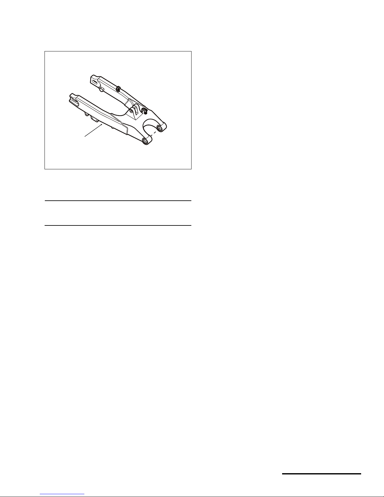
Inspect the swi ngarm for cracks, deep scratches,
or other damage.
Inspect the weldments (individual welded
components comprising the total swingarm) and
fastener fixtures for any sign of cracking or damage.
Place the vehicle on a stand with the rear wheel
suspended. The swingarm should move freely up
and down with no play side to side.
POTENTIAL HAZARD(S)
(1) Operating with a bent, corroded/rusted, cracked,
dented, or damaged fra me, subframe, swingarm or
other aluminum component.
(2) Attempting to repair the frame, subframe, or
swingarm on this vehicle.
WHAT CAN HAPPEN
(1) Riding on a damaged frame can lead to a
complete frame failure.
(2) Aluminum frame (and components) are heat
treated. Welding, drilling, or modifying the frame,
subframe, or swingarm may weaken the component
and result in complete failure leading to a serious
accident with subsequent injury or death.
HOW TO AVOID THE HAZARD
(1 & 2) Contact an authorized Cannondale
motorsports dealer for servicing if either the frame,
subframe, or swingarm is damaged; never try to
repair the frame, subframe, swingarm, or other
components.
1. Frame
2. Lower frame rails
3. Subframe
(2)
(1)
(3)
9
Printed : 1/9/02
9
If any damage to the sw ina rm is de tec ted , take
corrective action before riding. Contact an authorized
Cannondale motorsports dealer for servicing.
NOTE :
The swingarm is shown removed from the vehicle for
clarity.
1. Swingarm
(1)
© 2002 Cannondale Corporation - All Rights Reserved
10
Motorcycle Vehicle Labeling.fm
VEHICLE LABELING
Read and understand the labels on your vehicle.
Examples of the labels can be found in this section.
Warning labels contain information which is important
to your safety and that of anyone else who operates
the vehicle. Other lab el s provide important
information.
• The labels should be considered permanent
parts of the vehicle.
• If any label is missing, worn, damaged, or
becomes unreadable, replace it. Cannondale
offers replacement labels at no charge. A
label’s part number is printed in the lower
right corner of the label and here in the
manual. Contact an authorized Cannondale
Motorsports Dealer for replacements.
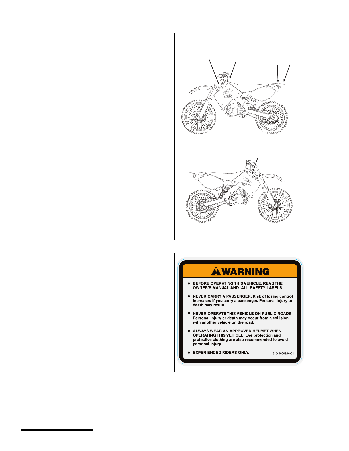
• Label locations are shown in the following
illustration. Always replace labels in the
correct position.
• Examples of the labels are shown on the
following pages. See the illustration for the
correct location of the warning labels on your
vehicle.
Label 1 P/N 315-5000266-01
(1)
(5,6)
(2)
(3)
(4)
11
Printed : 1/9/02
11
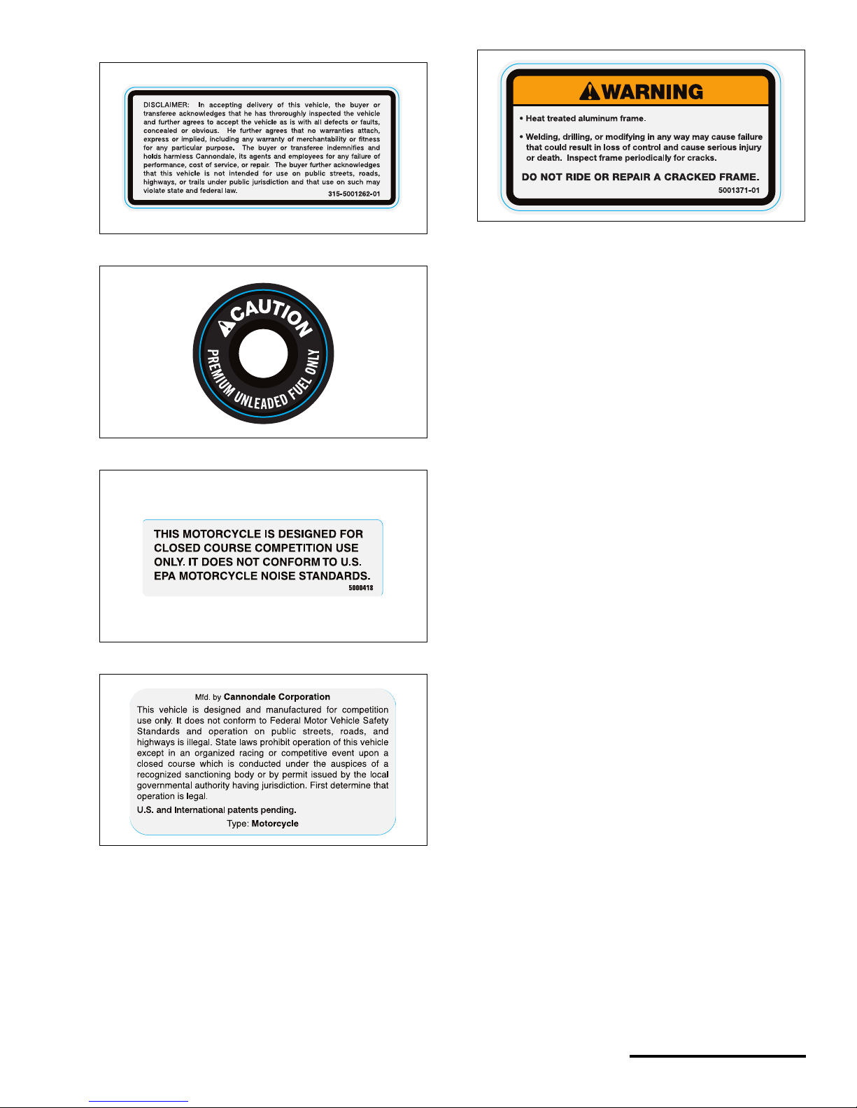
Label 2 P/N 315-5001262-01
Label 3
Label 4
Label 5
Label 6 P/N 315-6000477-01
© 2002 Cannondale Corporation - All Rights Reserved
12
Motorcycle Machine Identification.fm
MACHINE IDENTIFICATION
NOTE :
Your vehicle may differ from those shown in the
illustrations in this manual.
Record your vehicle’s identification numbers in the
spaces pro vided. Keep another record of the
numbers in a safe place; you may n eed them for
parts, service information, or theft recovery.
Your vehicle’s ID numbers identify it from others of
the same model type.
VEHICLE IDENTIFICATION
NUMBER (VIN)
The vehicle identification number (VIN) is locate d
on the left side of the steering head.
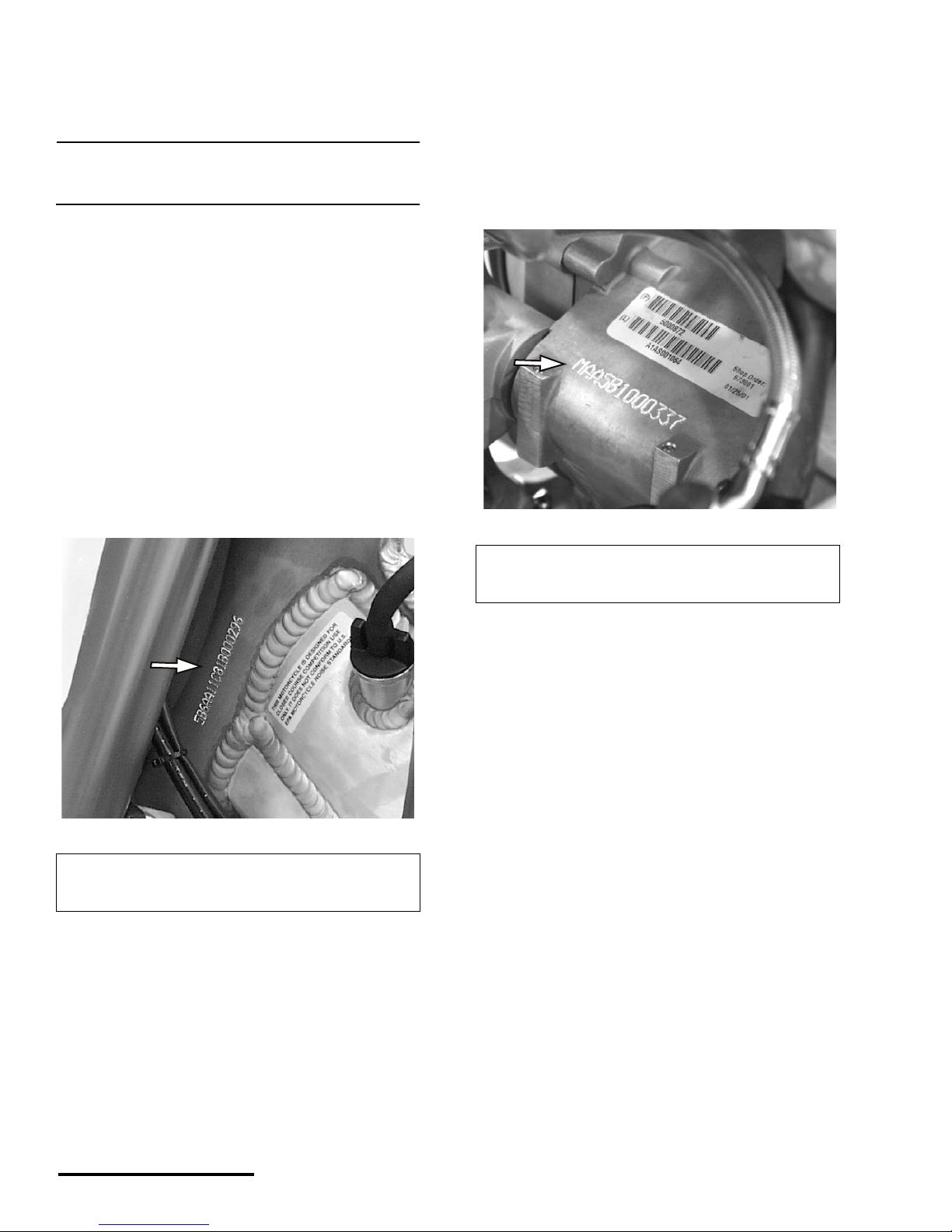
ENGINE SERIAL NUMBE R
The engine serial number is etc hed /st amped into
the rear area of the engine cran kcas e. Th e numb er
also appears on a metallic pla te affixed to the
crankcase area above the countershaft sprocket.
The number also appears on a te mpo ra r y fact ory
applied adhesive label in the same area.
1. Etched vehicle i dentification numbe r
Write your number here
XXXXXXXXXXXX
XXXXXXXXXXXX
1. Engine se rial number
Write your number here
XXXXXXXXXXXX
XXXXXX
XXXXXX
13
Printed : 1/9/02
13
PARTS & CONTROLS
This section des c ri bes the parts and control
functions found on your vehicle. Not all the items
found in this section may be installed on your vehicle.
If you have any questions about the parts, control
functions, or components installed on your vehicle,
consult your Cannondale Motorsports Dealer.
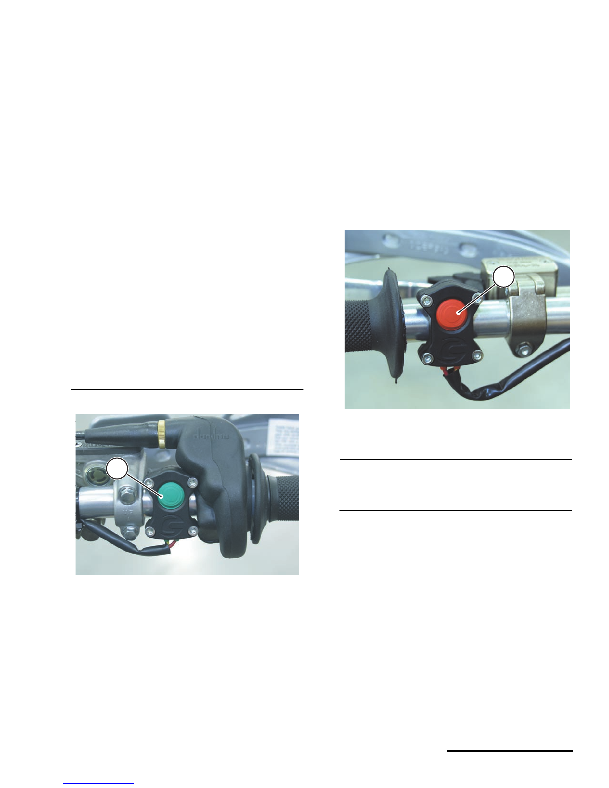
ENGINE START BUTTON
The engine start button is l oc ated on the ri ght
handlebar and is ( GREEN) in color.
Before attempting to start the engine, press it for 1
second to activate the eng ine ma nage men t system
circuits. Then, press and hold it to activate the starter
motor. But, be sure to read the Operation section of
this manual for a detailed explanation of the best
starting procedure.
NOTE :
When pressing the button to operate the starter,
motor hold it for no more than 2-3 seconds at a time.
ENGINE STOP BUTTON
The engine stop button is located on the left
handlebar. The button is (RED) in color.
Pressing it will shut of f a running e ngine. Or, press
it to deactivate the engine manage men t system
circuits.
Make sure this button operates properly be for e
starting out.
To test it, start the engine then press and hold the
button. When pressed the engine should stop
running.
NOTE :
The stop button is normally a closed circuit switch. If
the stop switch is damaged o r the wires are frayed
or torn, (circuit open) the engine may not start.
1. Engine start button
(1)
1
1. Engine stop button
(1)
1
© 2001 Cannondale Corporation - All Rights Reserved
14
Motorcycle Parts and Controls.fm
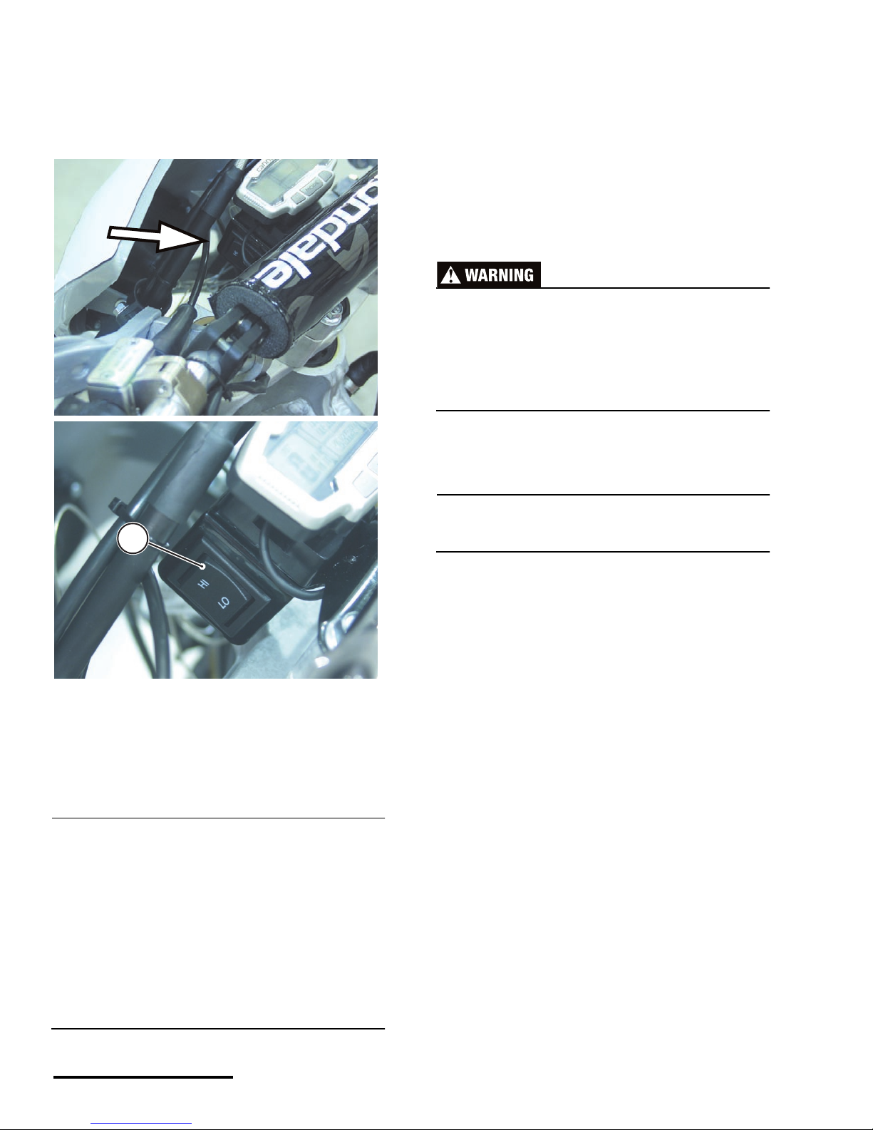
LIGHTING SWITCH
The lighting switch is used to activate the headlight
and taillight together. It is located on the ride
computer mounting bracket in front of the handlebar.
The taillight should turn on with the headlight in
either the HI or LO switch position. Be sure the
lighting operates pr op er ly before starting out.
NOTE :
The lights on your motorcycle are powered throug h
the engine management system relay. This relay
supplies voltage as long as the ECU tells it to. The
ECU itself has a 2 minute timer which will shut o ff
itself and the relay. If those two things are o ff, so is
the lighting, even if the switch is in either the HI or
LO position.
To turn the engine management system on, press
the engine START button quickly (1 second) without
holding to turn over the engine).
To test the headlight/taillight, quickly (1 second)
press the engine START button to activate the
engine management system. Toggle the switch
positions and observe that the headlight/taillight are
functioning properly. The HI and LOW intensity lamps
of the headlight should operate and the taillight
should remain lighted in both posi tions. If the
headlight or taillight does not work properly, check
the fuse and bulb. If the fuse or bulb is blown, correct
the problem before riding .
Select HI or LO intensity before moving off to
ride. Do not remove your hands from the
handlebar to toggle the switch while the vehicle
is moving. You could lose control and have an
accident.
NOTE :
Switch the lights off before attempting to star t the
engine.
Return the switch to the center position when the
lighting is not requ ir ed .
1. Headlight/ Taillight switch
1
15
Printed : 1/9/02
15
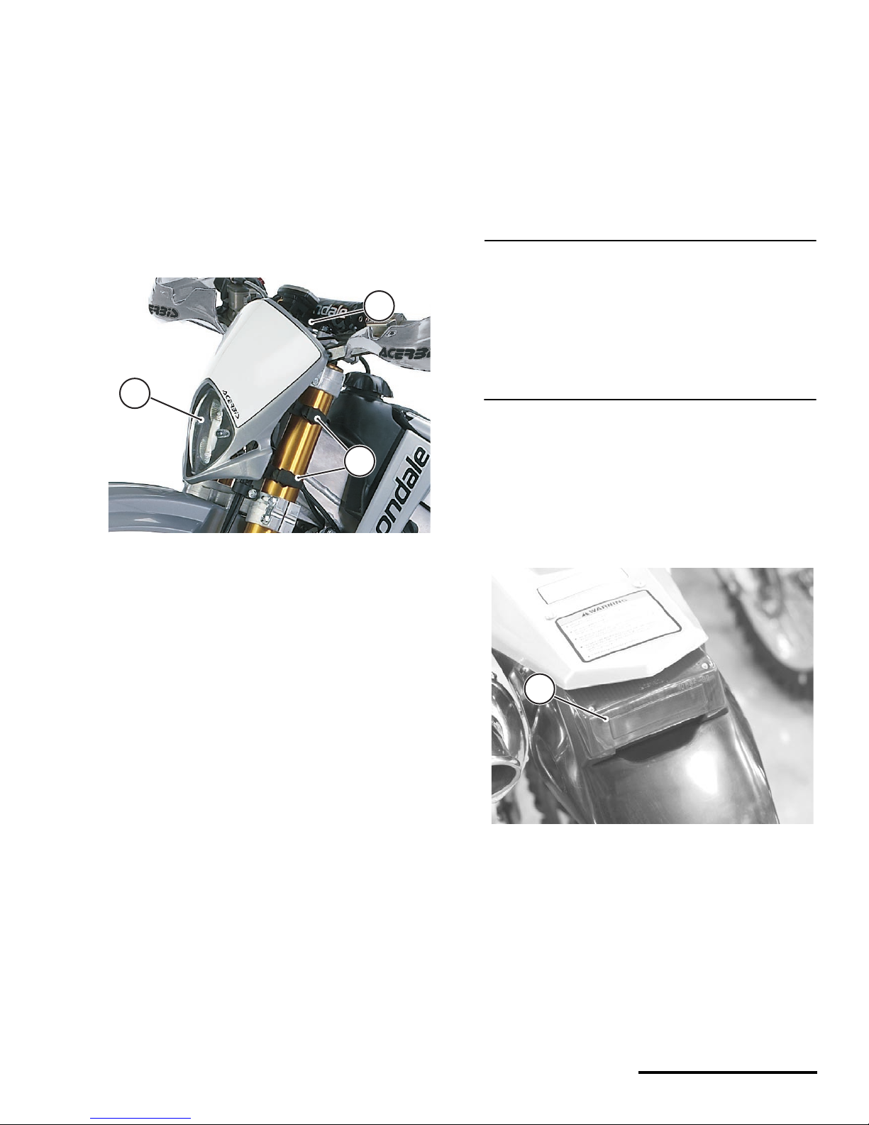
HEADLIGHT
The headlight is located at the front of the vehicle
and is activated with the headlight/ taillight switch.
The highlight can be switch to HI or LO intensity with
the headlight switch. Be sure the headlight is
fastened securely with the mounting straps and
operating properly (HI and LO inten sit y) befo re
starting out.
Details on bulb replacement can be found in the
Maintenance and Adjustment section of this manual.
TAILLIGHT
The taillight with the headlight/tai llight switch. It
should light in both the HI or LO switch position. It is
NOT a braking ligh t!
Make sure it is operating properly before starting
out.
NOTE :
Remember that the lighting circuits are energized
through the engine management system power
relay. This relay is controlled by the ECU. The ECU
will shut down the system automatically after 2
minutes if the engine is not started or the START
button has not been pressed. In short, the lights can
be turned on as long as the engine management
system is activated.
The taillight should be activated in both switch
positions (HI and LO). If it does not light, check to
see if a fuse or bulb replacement is needed. Correct
the problem before riding.
Details on bulb replacement can be found in the
Maintenance and Adjustment section of this manual.
1. Headlight
2. Mounting straps (left fork)
3. Headlight/Taillight switch
1
2
3
1. Taillight
1
© 2001 Cannondale Corporation - All Rights Reserved
16
Motorcycle Parts and Controls.fm
FUSES
The fuses for your vehicle are located inside fuse
holders under the seat.
Unless directed otherwise in a procedure, you
should always remove the fuses before working on
the vehicle.
Fuse replacement is described in the Maintenance
and Adjustment section of this manual.
SERVICE: Main fuse rating
10 A
SERVICE: Lighting fuse rating
10 A
When a fuse blows repeatedl y, it usually indicates
a short circuit or current overload in the electrical
system. The problem could be inte r mit tent or
constant. In either case, don’t ride the vehi cl e
because an electrical fire could lead to a serious
accident. If you experience frequent fuse “blows,”
have the vehicle inspected by an authorized
Cannondale dealer.
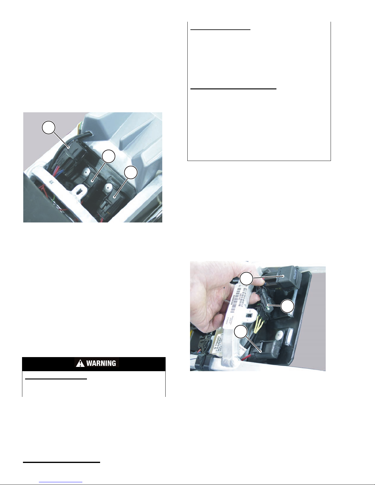
OPTIONAL LIGHTIN G
If you have an C440 or X440 model, you may
choose to install the available lighting systems. The
connection for optional lighting is located under the
seat near the main fuse and engine management
system relay. This connector is NOT protected by a
fuse, so do not improvise; contact your Cannondale
Motorsports dealer to in stall the optional li ghting
system.
1. Main fuse
2. Lighting fuse
3. EMS power relay
POTENTIAL HAZARD
Using an unspecified fuse or shorting the fuse
holder.
1
2
3
WHAT CAN HAPPEN
Using a fuse with a rating other than specified or
using other materials in place of the fuse will cause
damage to the system. A malfunctioning electrical
system increases the risk that you may be seriously
injured or killed while operating the vehicle. For
example, an electrical fire can develop from a
system overload or you could lose vehic le light ing.
HOW TO AVOID THE HAZARD
Always use a replacement fuse of the specified
rating.
Never use other materials in place of the fuse.
If a fuse blows immediately after replacement have
the electrical circuits checked by an authorized
Cannondale Motorsports Dealer.
Check the condition of the wiring harness and
connectors before replacing a blown fuse.
Make sure the lighting is switched off when
replacing a fuse.
1. Optional lighting tap (non-fused)
2. Main fuse
3. Engine Management System power relay
1
2
3
17
Printed : 1/9/02
17
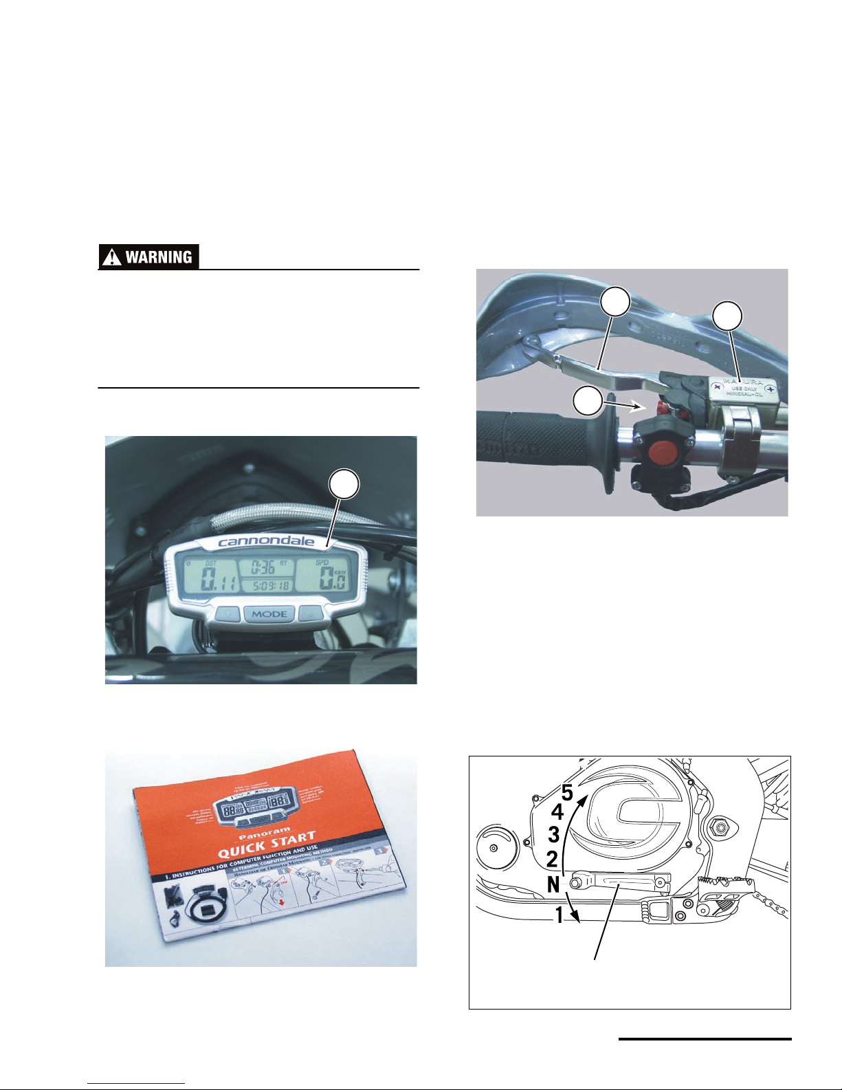
MULTI-FUNCTION RIDE
COMPUTER
The multi-function ride computer is located
between the handlebars.
Consult the manufacture r’s instruction manual
included with this manual for th e unit fea ture s and
operating instructions .
Never remove your hands from the handlebar
when riding the vehicle; you can lose control
and have a serious accident. Always stop the
vehicle on level ground before operating
(programming/setting) the computer.
CLUTCH LEVER
The clutch lever is located on the left side of the
handlebar.
Pull in the clutch lever (quickly) to disengage the
clutch, and release the lever (slowly) to engage the
clutch.
The lever position can be adjusted for individual
hand sizes. To adjust it, see the Maintenance and
Adjustment section of this manual.
SHIFT LEVE R
The shift lever is located on the left side of the
engine just in front of the left footpeg.
The transmission has five gears, “one down, four
up.” Neutral is located between first and sec ond
gears.
1. Multi-function ride computer
1. Manual
1
1. Clutch lever
2. Clutch reservoir
3. Lever position adjuster
1. Shift lever
3
2
1
(1)
© 2001 Cannondale Corporation - All Rights Reserved
18
Motorcycle Parts and Controls.fm
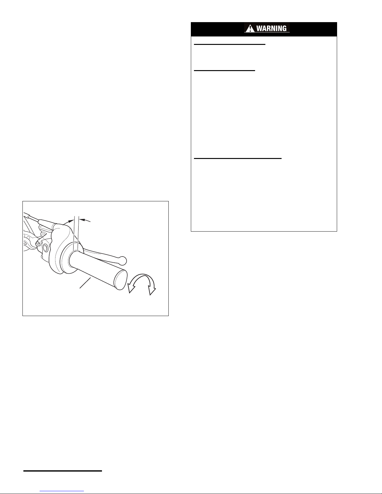
THROTTLE GRIP
SERVICE: Throttle lever freeplay
1/8 - 5/16 in (3 - 8 mm)
The throttle lever is located on the right han dle bar
and controls acceleration and deceleration of the
engine.
Before every ride make sure the specified freeplay
is available at the grip. Fre epl ay is the distance the
grip rotates before al l cab le slac k is tak en up. See
the illustration bel ow. Adjustment of the freepl ay is
described in the Maintenance and Adju stment
section of this m anual.
To accelerate, turn the lever towards you. To
decelerate, turn the grip away from yo u.
Make sure the throttle lever oper ate s properl y
before you ride. It should operate freely (e.g., without
binding, dragging, or sticking) and return to the
closed position automatically in all steering positions.
1. Throttle grip
a. Freeplay
b. Open throttle (accelerate)
c. Close throttle (decelerate)
(b)
(c)
(1)
(a)
POTENTIAL HAZARD(S)
(1) Stuck or damaged throttle
(2) Incorrect freeplay
WHAT CAN HAPPEN
(1) The throttle must return to the closed position
automatically when you release it. If it sticks you can
lose the ability to accelerate and decelerate the
engine which could result in an accident where you
could be seriously injured or ki lled .
(2) The throttle freeplay must be maintained as
specified, otherwise the engine speed could
increase when the handlebars are turned or when
the throttle is slightly grasped. Either situa tion c oul d
result in an unexpected acceleration of the engine
where you could be seriously injured or killed.
HOW TO AVOID THE HAZARD
(1) T es t th e o p e ration of the throttle before e ach ride.
Make sure it operates smoothly (with no sticking or
binding) in all steering positions. It should return
automatically to the closed position when released.
(2) Make sure the throttle freeplay is adjusted as
specified.
(1 & 2) If the throttle malfunctions or you can not
adjust the throttle to the specified freeplay, do not
ride the vehicle. Contact an authorized Cannondale
Motorsports Dealer for servicing.
19
Printed : 1/9/02
19
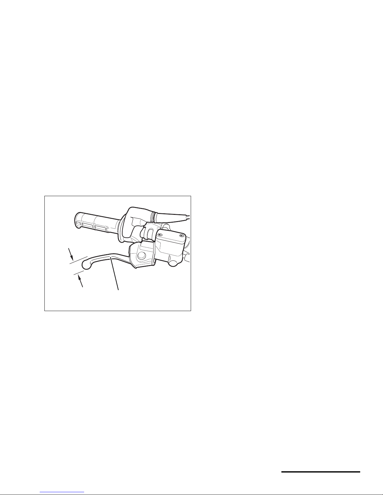
FRONT BRAKE LEVER
The front brake lever is l oc ated on the ri ght
handlebar.
Pull the lever against the handle grip to activate
the front brake.
Always make sure the brakes (front and rear) on
your vehicle operate properly before riding.
Make sure the lever has the specified freeplay.
Measure the freeplay at the tip of the lever. See the
illustration. Adjustment of the freeplay is described
in the Maintenance and Adjustment section of this
manual.
The position of the brake lever can be adjusted so
that control is comfortable when seated and
standing. Adjustment of the lever position is
described in the Maintenance and Adjustment
section of this manual.
SERVICE: Brake, lever, front, freeplay,
maximum
0.8 inches (20 mm)
1. To measure the freeplay, gently pull in the
brake lever until the play is taken up, then
measure distance (a) at the end of the brake
lever. Adjust if out of specification.
1. Front brake lever
2. Freeplay
(a)
(1)
© 2001 Cannondale Corporation - All Rights Reserved
20
Motorcycle Parts and Controls.fm
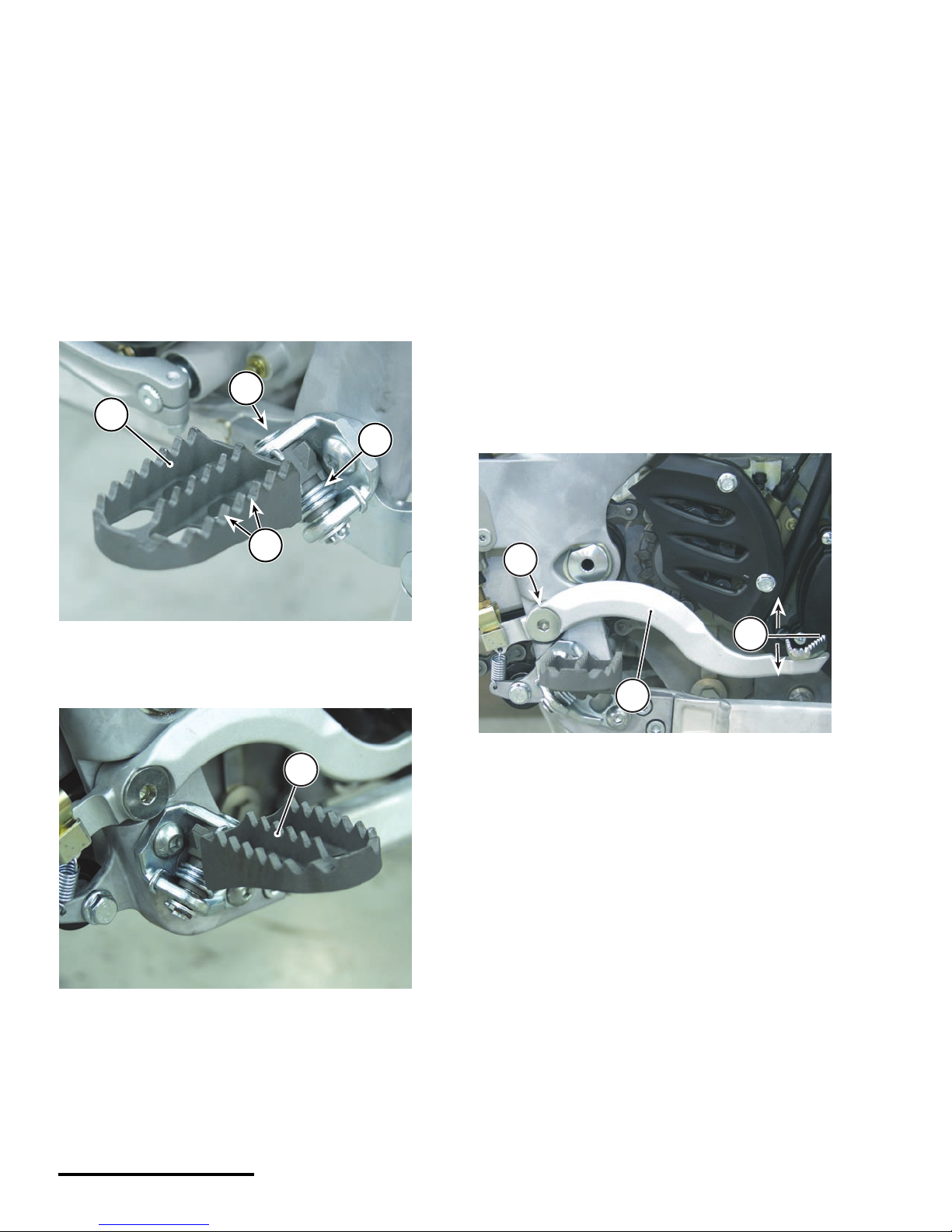
FOOTPEGS
The right and left footpegs on your vehicle should
be fastened securely and free of any collected mud
or dirt. The footpegs should move freely (up and
down on the pivot) and not bind - springing back
when released.
After cleaning the vehicle, always lubricate the
footpeg pivot points with some clean engine oil.
Move the pegs up and down to work the lubricate in.
Don’t use grease; grease will catch and col lect di rt
and small particles which will damage the pivot point.
Make sure the teeth are in good condition.
REAR BRAKE PED AL
The rear brake pedal is located on the right side of
the vehicle.
Press it firmly with your foot to apply th e rear
brake. Test to make sure it is operating correctly
before you ride. When pressed, braking force should
be applied to the rear brake disc . Braki ng force wil l
increase the mor e yo u press down on the pedal.
The rear brake pedal height can be ad ju st ed fo r
comfort. To adjust it, see the Maintenance and
Adjustment section of this manual.
After cleaning the vehicle, be sure to lubricate the
pedal pivot point with clean engine oil. It is not
necessary to remove the bolt, simply apply a few
drops of oil to the bolt and work the pedal up and
down.
1. Left footpeg
2. Pivot
3. Spring
4. Teeth
1. Right footpeg
1
3
2
4
footpegs
1
1. Rear brake pedal
2. Pivot
a. Pedal height
1
2
1
a
2
21
Printed : 1/9/02
21
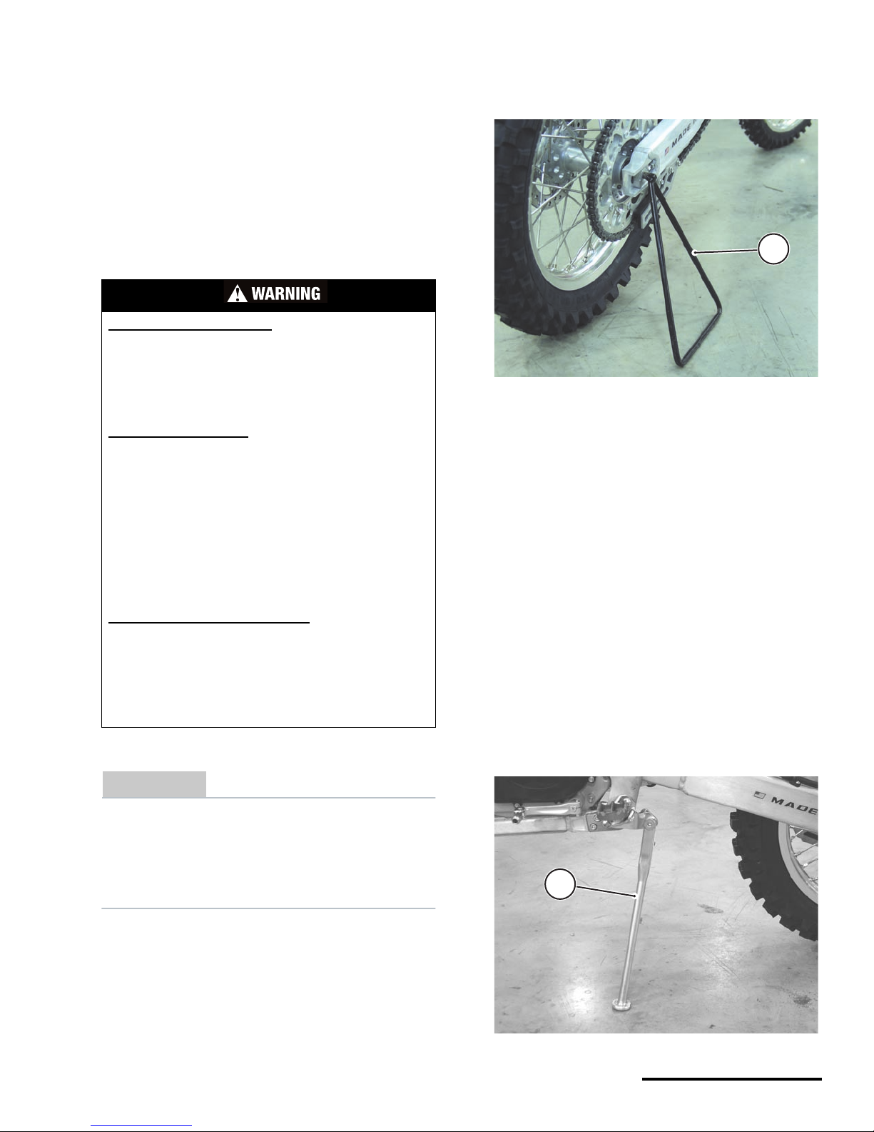
SIDE STAND OR KICKSTA N D
The side stand or kickstand (on equipped vehicles)
can be used to support the ve hic le on firm level
ground when not in use (wi th engine off). It is only
designed to support the weight of the vehicle; so do
not apply extra weight when using it (e.g., leaning on
the bike or sitting on it with the stand or kickstand in
place).
The kickstand is mounted on the left side of the
motorcycle.
CAUTION
Turn the handlebars to the left side of the
vehicle when using the kickstand. Stability of
the motorcycle is greater with the wheel
pointing to the left; risk of toppling is increase
with the handlebars turned to the right.
To use the side stand (triangle shaped and
removable from the vehicle), position the vehicle on
firm level ground. Hold the vehicle upri ght and ins ert
the side stand completely into the hole in the rear
axle shaft on the right side of the vehicle. Tilt the
vehicle toward the stand allowing the weight of the
vehicle to rest on the stand. Make sure there is no
danger of the vehicle falling over before leaving the
vehicle unattended.
The kickstand is located on th e l eft side of the
vehicle behind the le ft fo otpe g. It is de si gned to
support only the weight of the vehicle when it is not in
use (with the engine off).
To use the ki c k stand, pos ition the veh ic le on firm
level ground. Fold the kickstand down and rest the
weight of the motorcycle on it. Turn the handlebars,
to the left (toward the k ickstand) side of the
motorcycle; this shifts more of the weight toward the
stand reducing the potential of the vehicle to tip on its
right side if bumped. However, the kickstand
Make sure the kickstand is folded up as far as
possible and is firmly attached (not wobbling) on the
mount before every ride.
After cleaning the vehicle, apply some cle an
engine oil to the pivot point and work the stand up
and down to work in the oil.
POTENTIAL HAZARD(S)
(1) Sitting or leaning on the vehicle
(2) Riding with the side stand attached, the kick
stand down, or not fully upright.
(3) Working on the vehicle with the side stand or
kickstand.
WHAT CAN HAPPEN
(1) The side stand and kickstand are designed to
support only the weight of the vehicle. If you sit or
lean on the vehicle, the additional weight could
cause the vehicle to fall over.
(2) The stand can cause you to lose control of the
vehicle.
(3) The motorcycle can fall onto you.
In any of the cases above, you can be serious
injured or killed.
HOW TO AVOID THE HAZARD
(1) Never sit or lean on a vehicle.
(2) Remove th e side stand ; lift the kick stand before
riding.
(3) Always place th e vehicle on a work stand when
performing maintenace. Ask your Cannondale
Motorsports Dealer about motorc y cle work stands.
1. Side stand
1. Kickstand (shown supporting weight of the vehicle )
1
1
Kick stand down
1
© 2001 Cannondale Corporation - All Rights Reserved
22
Motorcycle Parts and Controls.fm
HANDGUARDS
The handguards are located on the ri ght and lef t
sides of the handlebar directly in front of the handle
grips.
These guards are designed to only offer limited
hand protection. Make sure you read the warning
following a description of the guards.
Make sure the han dgu ar ds ar e in good co ndi tio n
and fastened securely before riding. The handguards
should not interfere with operation of the vehicle
controls. Tighten the mounting harware securely.
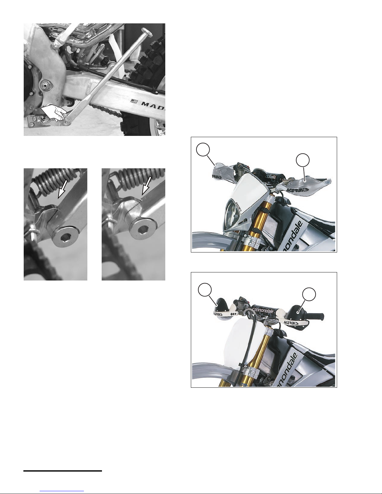
This photo shows the ki ck s tand in the operatin g
position. See a close-up of the area indicated in the
next photo.
The image on the left shows a kickstand that is in
the correct operating position. Notice that there is no
gap (1) present between the kickstand leg and the
plate.
The image on the right shows a kickstand in the up
position but “hanging.” Notice that gap between the
leg and the plate. The kickstand may be dam age d
(e.g., bad spring, bent leg or plate). This condition
must be corrected before riding th e vehicle.
YES
YES
NO
NO
1. Type 1 handguard (left side)
2. Type 1 handguard (right side)
1. Type 2 handguard (left side)
2. Type 2 handguard (right side)
1
2
1
2
23
Printed : 1/9/02
23
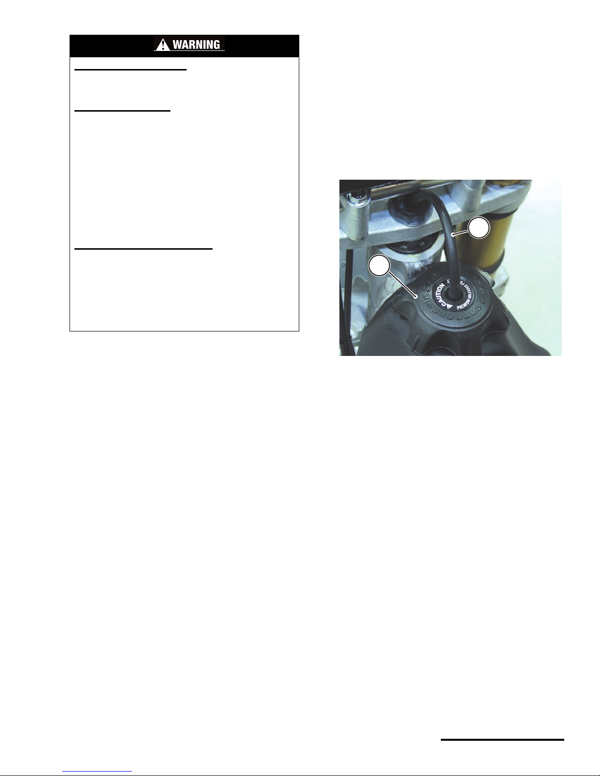
FUEL CAP
Remove the fuel cap to fuel the motorcycle. You
should fill the vehicle wi th the specif ied gasoline
before each ride. See the Fluids section of this
manual.
To open: Turn the cap counter-clockwise.
To close: Reinstall the fuel cap and turn it
clockwise until it is secured.
POTENTIAL HAZARD(S)
(1) Interference with the vehicle controls
(2) Crushed, mangled, or injured hands
WHAT CAN HAPPEN
(1) If a handguard is loose or damaged, it can
interfere with the controls possibly preventing your
hands from operating the controls as required.
(2) The hand guards (TYPE 1 and TYPE 2) provide
limited protection against trail hazards [e.g., wind
deflection, small branches, “roost” (the dirt and
debris thrown backward from a leading vehicle)].
The guards WILL NOT protect you (your hands) from
injury in a crash.
In either case above (1,2) you can be severely
injured or killed.
HOW TO AVOID THE HAZARD
(1 & 2) The handguards should be inspected before
every ride to ensure that they are mounted securely
and will not interfere with the vehicle controls. If
they are damaged or loose, take corrective action.
If you have any questions about the conditions or
intended use of the handguards, contact your
Cannondale Motorsports Dealer for assistance.
1. Fuel cap
2. Breather (vent) hose
1
2
© 2002 Cannondale Corporation - All Rights Reserved
24
Motorcycle Fluids.fm
FLUIDS
FUEL
Use only clean, fresh unleaded gasoline with a
minimum Anti-Kno ck Inde x of 92 or highe r.
Fill the tank with the specified fuel before every
ride.
We recommend that the inline fuel filter is replaced
every 5 hours of operation for the best performance.
See the Maintenance and Adjustment section of this
manual.
CAUTION
If engine “knocking” or pinging occurs, use a
different brand of gasoline or a higher octane
rating.
Never experiment by using fuels other than
the recommended type in this vehicle. Other
fuels or additives that are not designed
specifically for this vehicle can severely
damage the engine and its supporting
components (e.g. fuel system, sensors, tank,
hoses, etc.)
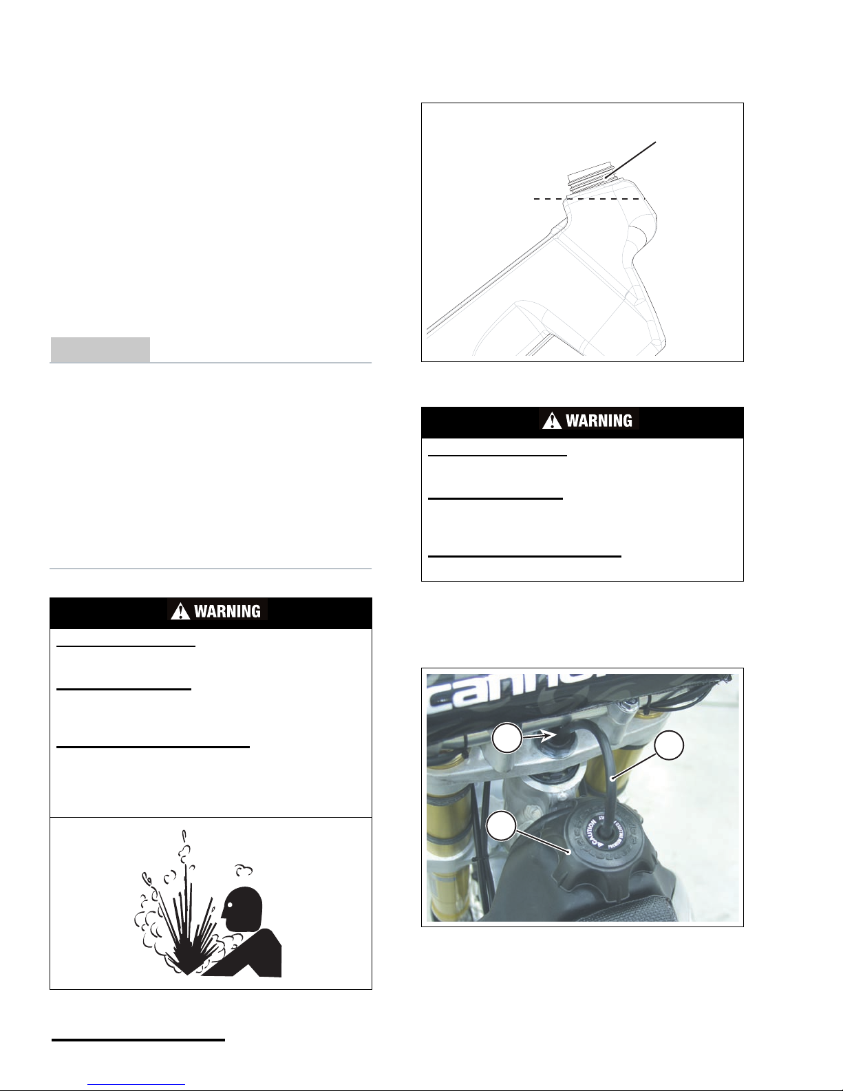
1. Remove the fuel cap and fill the tank wi th fuel
until it reaches the bottom of the filler neck.
2. Tighten the fuel cap securely and make sure
the breather hose is undamaged and routed
correctly.
POTENTIAL HAZARD
Improper care when handling fuel.
WHAT CAN HAPPEN
Fuel is highly flammable, spilling it can cause a fire
or explosion.
HOW TO AVOID THE HAZARD
Work in a well-ventilated area which is free of
sources that could ignite any spilled fuel
accidentally (e.g. cigarettes, welders, torches,
grinders, electric shop tools, etc.)
1. Fuel level
2. Filler neck
POTENTIAL HAZARD
Overfilling the fuel tank
WHAT CAN HAPPEN
Fuel expands due to heat (e.g., engine, sun) a nd ma y
overflow if the tank is ov erfilled, resulting in a fire.
HOW TO AVOID THE HAZARD
Stop adding fuel when the correct le vel is re a ched.
1. Cap
2. Breather (vent) hose
3. Steering stem hole
(1)
(2)
2
1
3
25
Printed : 1/9/02
25
BRAKE FLUID
Check the brake fluid in both the front and rear
systems before every ride.
Use only clean DOT #4 brake fluid from a sealed
container. Do not mix brake fluid types or brands.
Have the brake fluid in both systems replaced
every year.
CAUTION
Avoid spilling brake fluid on painted, plastic
or rubber parts; damage will result. Place a
shop towel or rag over these parts when
servicin g the brake system. Wipe up any spills
immediately.
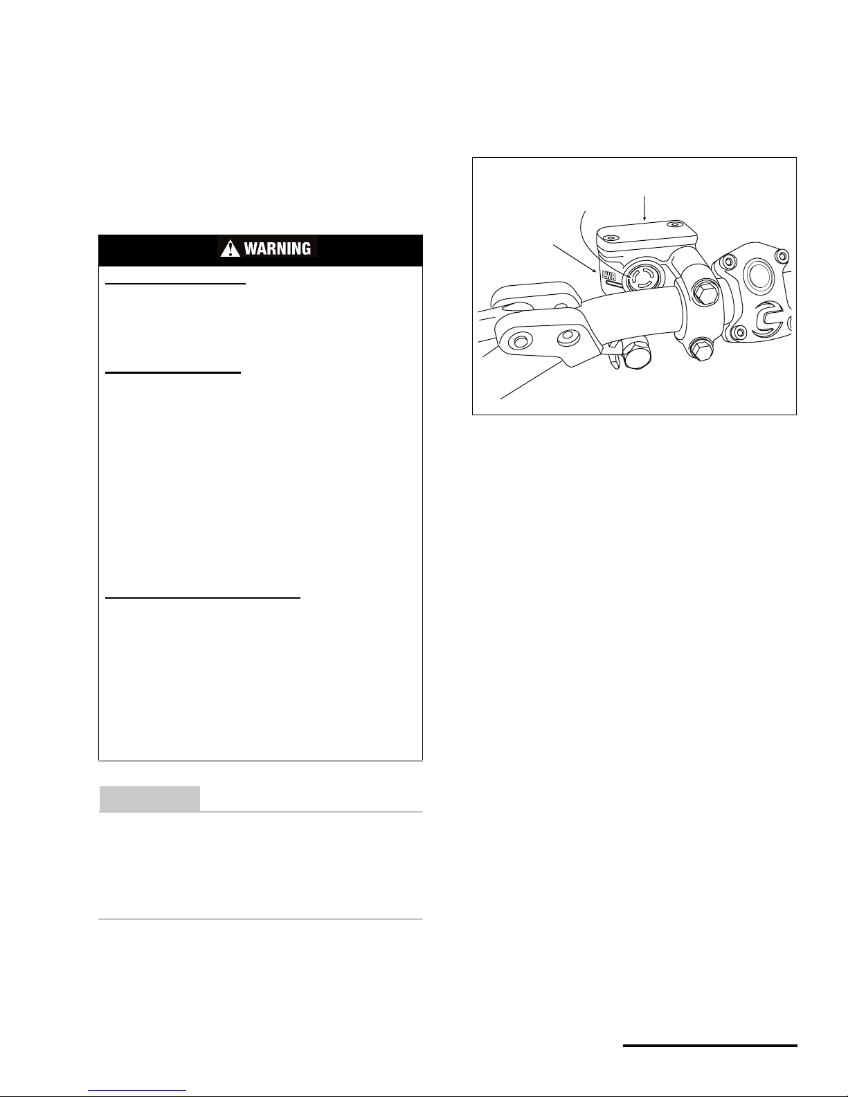
FRONT BRAKE
1. To check the front syst em, start by leveling the
top of the master cylinder (mounted on the right
handlebar).
2. Inspect the fluid level through the site glass. If
the fluid level i s below t he ‘LWR’ mark, add the
specified brake flu id until the fluid is at the top
of the window.
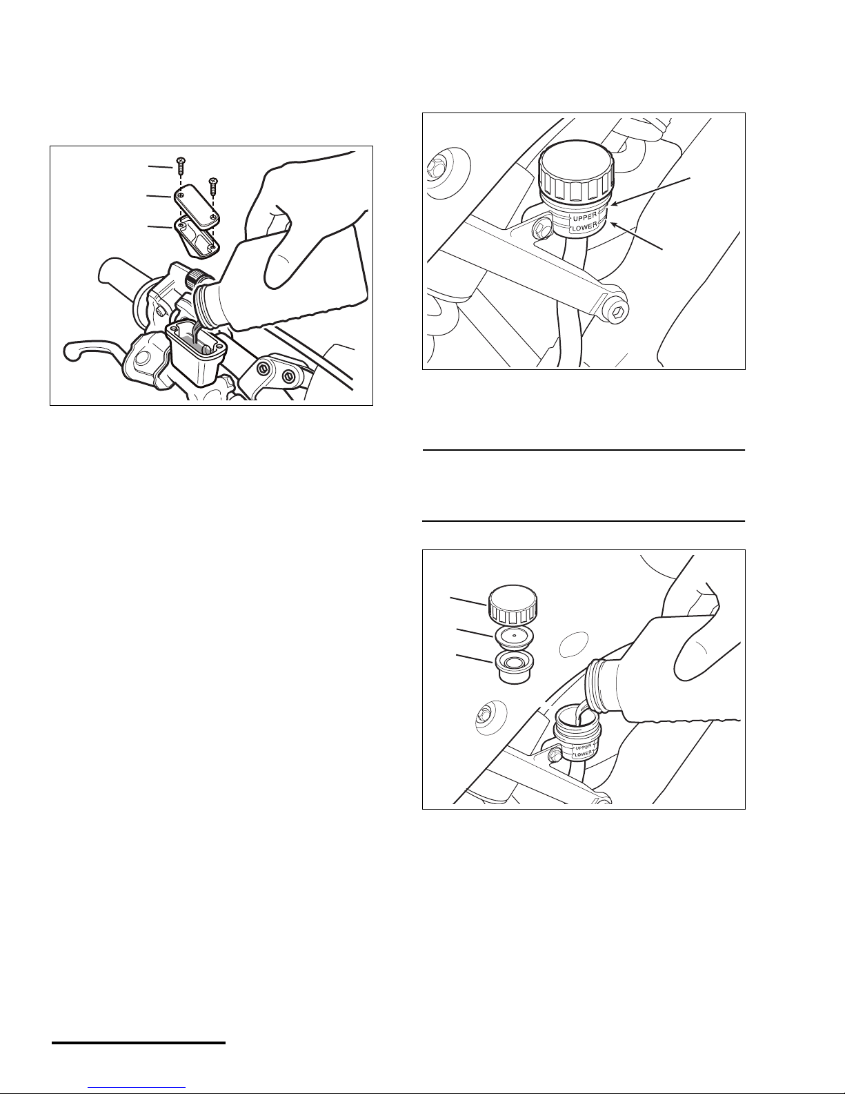
3. To add fluid, make sure the area around the
master cylinder is clean to prevent
contamination which can lead to a loss of
braking force. Remove the screws, cover and
diaphragm from the master cy linder.
POTENTIAL HAZARD
(1) Eye and skin injury, death if swallowed
(2) Mixing fluid types or brands
(3) Fluid from unsealed containers
(4) Low fluid level
WHAT CAN HAPPEN
(1) Brake fluid is a hazardous substance. It can
cause injury to your eyes or skin if you touch it. If
swallowed it can cause death.
(2) Mixing types and brands can damage the brake
system leaving you without brake s.
(3) A container of brake fluid once unsealed can
begin to absorb moisture from the atmosphere - if
used in the brake system, the moisture will reduce
braking force. You could lose your brakes and have
an accident resulting in injury or death.
(4) Low brake fluid can allow air to enter the system
and this will reduce braking power. Again, you could
have an accide nt and be s er iously inju r ed or killed.
HOW TO AVOID THE HAZARD
(1) Always wear eye and hand protection when
working with brake fluid. Keep brake fluid out of the
reach of children and animals. If ingested contact a
doctor immediately.
(2,3) Always use DOT 4 brake fluid from a sealed
container. Don’t mix fluids or use opened fluids.
Have the system drained and refilled by an
authorized Cannonadale Motorsports dealer if you
suspect fluids have been mixed accidentally.
(4) Check the fluid level before riding the ve hicle.
1. Master cylinder
2. Site window
3. ‘LWR’ mark
(2)
(3)
(1)
© 2002 Cannondale Corporation - All Rights Reserved
26
Motorcycle Fluids.fm
4. Pour DOT#4 brake fluid from a sealed
container until the flui d level rises to the top of
the site window and no higher. If you fill above
the window the fluid will overflow when the
diaphragm and cover are re-installed.
5. Reinstall the front brake master cylinder
diaphragm and cover. Tighten front master
cylinder cover sc rews to the specified torque.
TORQU E : Front brake master cylin der
cover screws
1.4 lbf• ft (1.9 N •m)
REAR BRAKE
1. To chec k the re ar sy st em , leve l the rea r brake
master cylinder reservoir. The fluid level should
be above the ‘LOWER’ mark.
2. If the fluid level is below the ‘UPPER’ mark,
remove the cap and add the specified brake
fluid until it reach es the ‘UPPER’ mark.
NOTE :
Do not fill the brake master cylinder above the
‘UPPER’ mark or the fluid will overflow when the
diaphragm is installed.
3. Install reservoir diaphragm, diaphragm plate
and cap.
1. Front brake master cylinder cover screws
2. Front brake master cylinder cover
3. Diaphragm
(1)
(2)
(3)
DOT 4
1. ‘LOWER’ mark
2. ‘UPPER’ mark
1. Reservoir cap
2. Diaphragm plate
3. Diaphragm
(2)
(1)
DOT 4
(1)
(2)
(3)
27
Printed : 1/9/02
27
ENGINE OIL
See the Model Specification section in this
manual for the recommended engine oil type and
capacity.
Check the engine oil level before every ride.
Clean the engine oil filters (screen type) or replace
with new ones (paper el ement type) in accordanc e
with Maintenance Schedule in this manual.
Service more frequently when operating in/under
extreme conditions.
CHECKING ENGINE OIL
You have to start and run the engine for 1 minute,
shut the engine off, wait another minute befor e
checking the oil level.
The engine and exhaust system are extremely
hot and take time to cool after you shut the
engine off. Work carefully to avoid hot surfaces.
You can be burned severely.
1. Position the vehicl e upr ight on a stan d.
2. Start the engine and allow to run for 1 minute at
idle speed, then turn off the engine.
3. Wait 1 minute for the eng ine oil to settle in side
the spar.
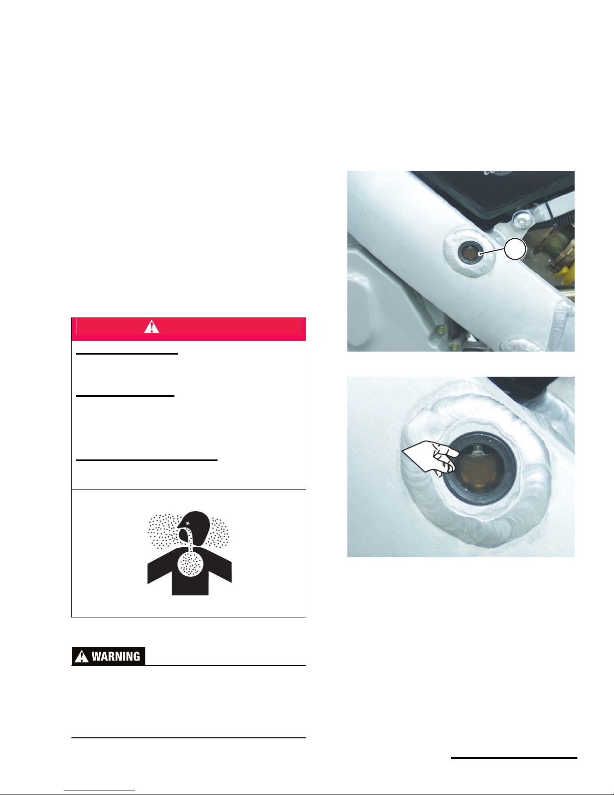
4. Inspect oil level in the inspection window on the
left frame spar.
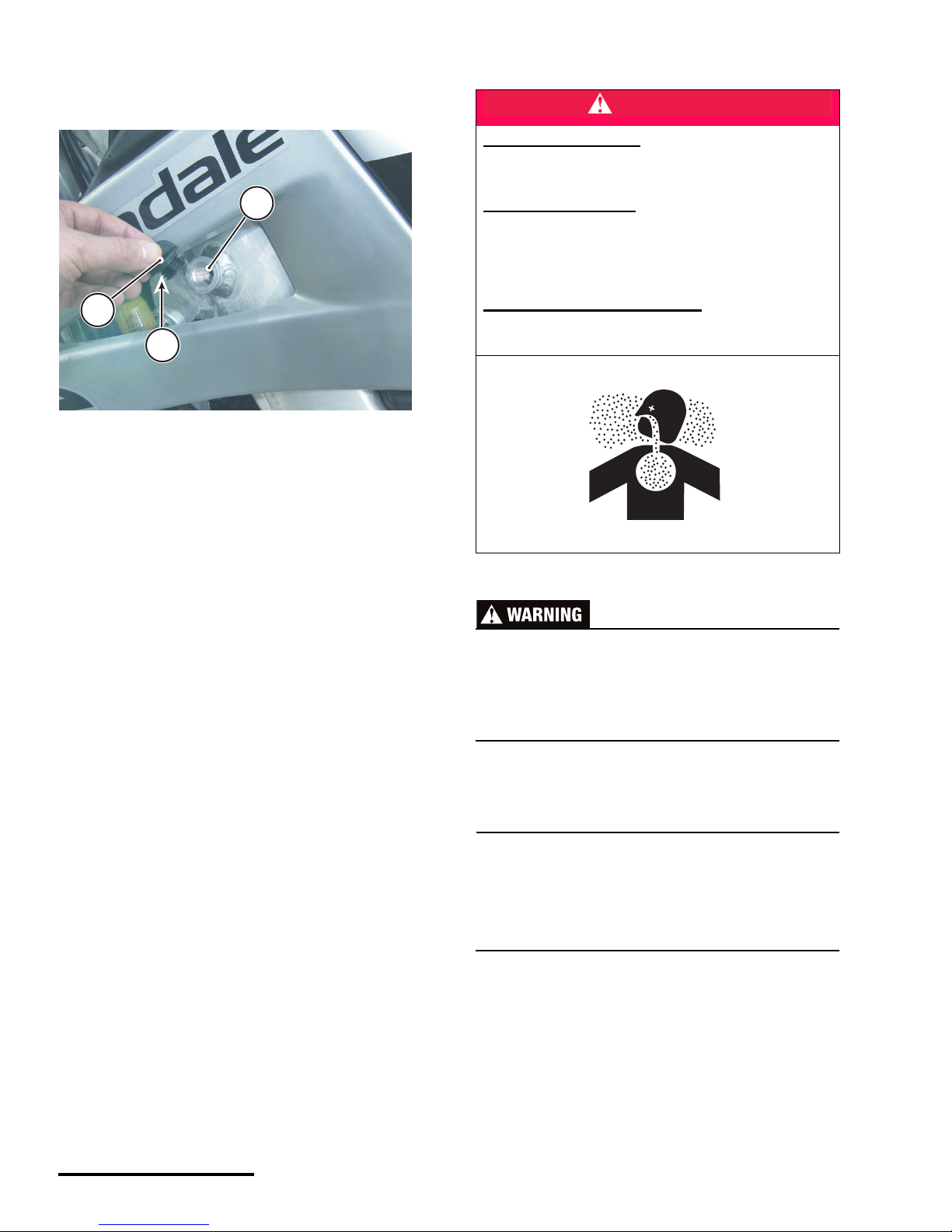
5. If the level is low (cannot see oil in the window),
add a sufficient amount of oil to raise it to the
correct level. Add at the filler hole using a clean
DANGER
POTENTIAL HAZARD
Running the engine indoors.
Breathing exhaust ga se s
WHAT CAN HAPPEN
Running the engine indoors will expose you to
dangerous exhaust gases. Breathing carbon
monoxide gas leads to poisoning, asphyxiation, and
death. This will happen rapidly and without notice.
HOW TO AVOID THE HAZARD
Never operate the vehicle indoors even for brief
periods of time.
1. Inspection window (left frame spar)
This is a close-up photo of the inspection window
showing the oil inside the spar an d its ‘level’
observed wit h th e ve hi cl e he l d up ri gh t . Th is oil level
is OK. The “level” of the oil should be visible in the
window.
1
© 2002 Cannondale Corporation - All Rights Reserved
28
Motorcycle Fluids.fm
funnel. If you see that the level is too high,
drain some out using the left spar drain bolt
until the oil level is visible through the window.
CHANGING ENGINE OIL AND CLEANING
THE FILTERS
Your vehicle has two engine oi l filt ers. One filte r is
located within the engine oil pressure pump housing.
The other filter is located in si de the cr an kc ase inl et
fitting. We highly recommend cleani ng (o r repla ci ng)
both as directed.
Clean (the screen type) or replace (the paper
element type) engine oil filters every time you change
the oil.
The engine and exhaust system are extremely
hot and take time to cool after you shut the
engine off. Work carefully to avoid hot surfaces.
You can be burned severely.
NOTE :
Remove the spar engine oil filler cap (left spar) when
draining.
When refilling engine oil, add slowly and recheck
level frequently so as not to over fill the system.
1. Position the vehicle upright on a stand.
2. Start engine and allow to run briefly to warm
the engine oil. Then, turn the engine off.
1. Engine oil filler hole
2. Cap
3. O-ring
1
3
2
DANGER
POTENTIAL HAZARD
Running the engine indoors.
Breathing exhaust gases
WHAT CAN HAPPEN
Running the engine indoors will expose you to
dangerous exhaust gases. Breathing carbon
monoxide gas leads to poisoning, asphyxiation, and
death. This will happen rapidl y and without notice.
HOW TO AVOID THE HAZARD
Never operate the vehicle indoors even for brief
periods of time.
29
Printed : 1/9/02
29
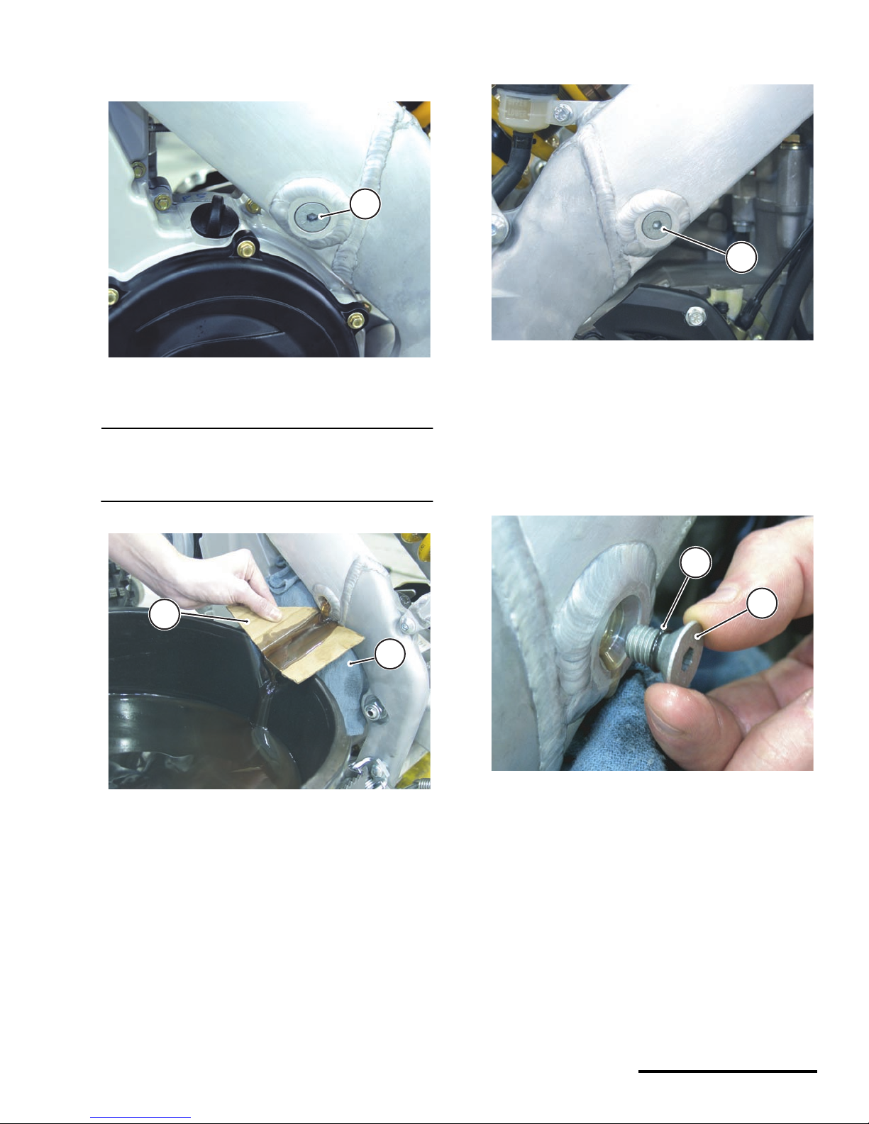
3. Remove the left spar drain bolt and drain the
contents into an oil pan.
NOTE :
Position a clean shop towel behind a folded piece of
thin cardboard to channel or direct the flow of oil
from the spar drain bolts into your oil pan.
4. When the spar flow is reduced, have an
assistant hold the handlebars and slightly tilt
the vehicle toward the oil pan to drain any
remaining oil.
5. Drain the right spar in the same way.
6. For both the left and right s par bolt, inspe ct the
spar bolt O-ring. Replace it with a new one if
you find any tears, rips, or if it is distorted in
shape. Make sure the bolt threads are clean.
Apply some clean en gine oil to the thr ead s a n d
O-ring and reinstall. Tighten the bolt(s) to the
specified torque.
TORQUE : Spar engine oil drain bolts
15.0 lbf•ft (20.3 N•m)
1. Left spar drain bolt
1. Shop towel
2. Folded cardboard
1
2
1
1. Right spar drain
1. Spar drain bolt
2. O-ring
1
2
1
© 2002 Cannondale Corporation - All Rights Reserved
30
Motorcycle Fluids.fm
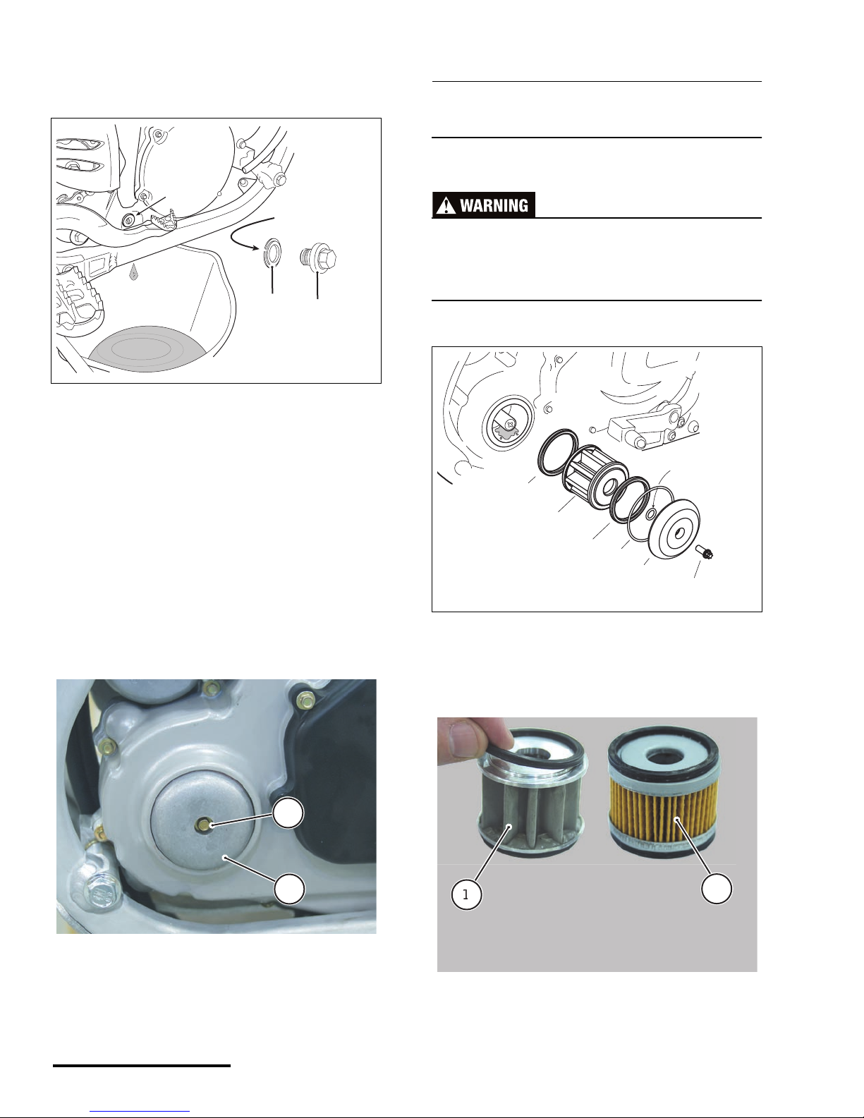
7. Remove the engine oil crankcase drain bolt
and sealing washer and allow the oil to drain
into your oil pan.
8. Apply some anti-seize compound to the
threads of the drain bolt. Install the sealing
washer onto the bolt so t hat the flat side faces
the crankcase a nd install the bolt and washer
into the crankcase. Tighten the bolt to the
specified torque.
TORQU E : Engine oil crankcase drain b olt
6.0 lbf• ft (8.1 N •m)
9. Position your oil p an under the engine oil filter
cover and remove the bolt and the fi lter cov er.
NOTE :
Be sure to note the two O-rings in the cover when
you remove it.
If the installed filter is the scr een type, remove the
seal, oil filter (screen) and oil seal from the filter
housing.
1. Bolt
2. Sealing washer
3. Crankcase drain hole
a. Sealing washer (flat side)
1. Bolt
2. Cover
(3)
(a)
(1)
(2)
1
2
1. Bolt
2. Cover
3. O-ring
4. O-ring
5. Filter seal
6. Filter (screen)
1. Screen type filter (with seals)
2. Paper type filter (glued seals)
(1)
(2)
(3)
(4)
(6)
(5)
(5)
 Loading...