

Cannondale ATV, 2002 Cannibal, 2002 Speed, 2002 Blaze, 2002 Moto440 Owner's Manual

ATV SPORT REALITY
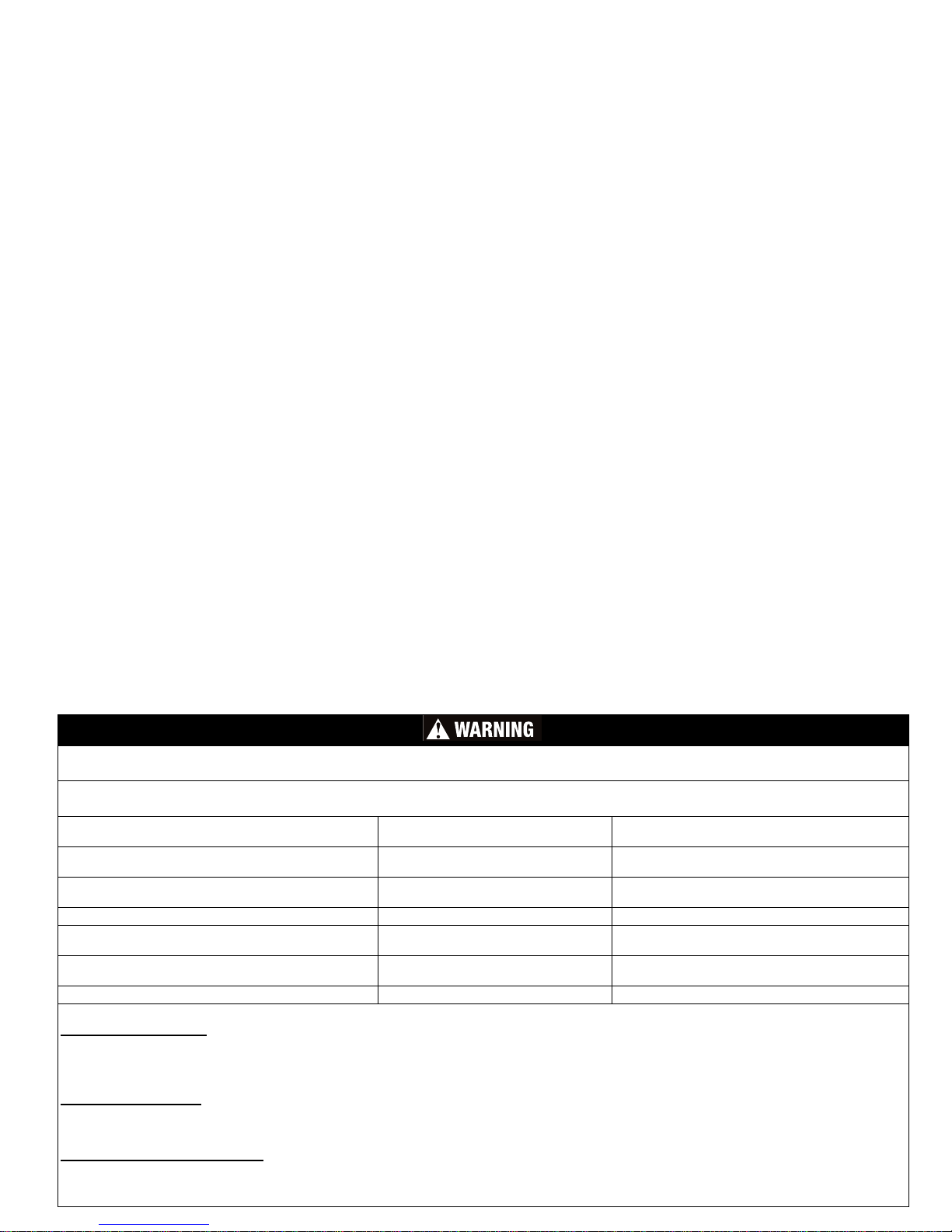
STOP! - If you have the impression that four wheels give you the stability of a car, you are wrong. If you have the impression that an ATV is simple to
drive and similar to those other vehicles, you are wrong. The risks involved are at least equal to those faced when riding a motorcycle.
CHARACTERISTIC PURPOSE REALITY
Example: Sharp knife Useful tool for cutting Risk of cutting yo u rs elf
No restraint system, no body, no protective structure Rider must be able to shift weight Motorcycle- like risk, rider can fall or fly off and is
exposed, unprotected
Very high power-to-weight ratio Thrilling acceleration, co m petition
performance
Relatively easy to wheelie, requ ires focus and skill to
stay ahead of machine
Short wheelb ase Maneuverable in woods, c o m pact Relatively easy to whee lie, to turn over backwards or
pitch over forward
Narrow track Maneuverable in woods, narrow trails Relatively easy to turn over
High ground clearance, high center of gravity Clearance for obstacles, more suspension
travel
Relatively easy to turn over
Soft, high t ra c tion tires Traction and flotation on soft, loose
surfaces
Grip on hard surface (pa vement) makes it easy to turn
over
Totally unsuited and illegal for road us e Designed exclusively for off road High risk of turn ove r or co llision if you ride on.
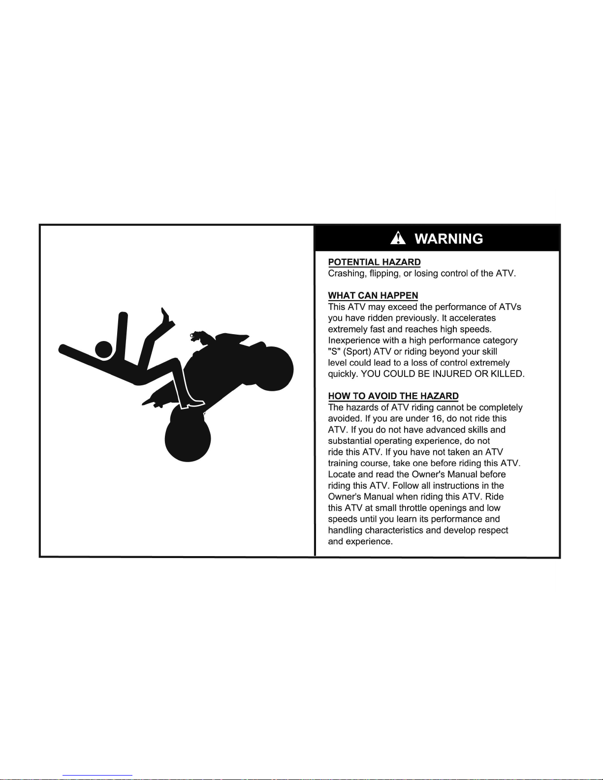
POTENTIAL HAZARD
Given the realities of spor t ATVs and/or the limit s of your ow n ridin g abilitie s, you may lo se co nt ro l. The limits ar e impos sib le to be sp ecific about because of
the variation in terrain and rider ability are nearly unlimit ed. If you chose to ride an ATV, you must understand and re sp ect the reality of the above.
WHAT CAN HAPPEN
You could lose control, have an accident an d be se ver ely injured, paralyzed or killed.
HOW TO AVOID THE HAZARD
The hazards of ATV riding c anno t be completely avoided. They can be minimized with training, good judgement, experience, use of helmet, protective gear and
development of sk ills in weight shifting, throttle and brake control . Readi ng an d un de r sta nd in g thi s Owne r’s Manual and warning labels, watching and understanding the ATV safety video and completing an ATV training course are essential and can begin your learning process.

FOREWORD
Experienced Riders Only
All Cannondale motorsports products are high
performance, sport and/or competition machines and
should only be operated by licensed competition riders in
excellent p hysical condition. Op erators should be welltrained and experienced in the operation of high
performance competition vehicles .
• This vehicle is not for beginners or the
inexperienced.
• Before you ride this vehicle, read this Owner’s
Manual thoroughly and understand all of the
instructions, warnings, cautions, and notes
presented.
About this manual
The purpose of this manual is to provide the vehicle
owner with important safety, service, maintenance, and
tuning information. Read and understand this manual
before operating or working on the vehicle. Keep your
Owner's Manual on the ve hic le while you ride. If you lose
this manual, contact an authorized Cannondale
motorsports dealer for a replacement.
• This manual contains standard ATV industry
safety information required to be a part of ATV
Owner’s Manuals. It also contains Cannondale
specific model information.
• Read and understand the entire procedure before
performing any work. If you are unfamiliar with or
doubt your own abilities to complete a proced ure
as described, have an authorized Cannondale
motorsports dealer service your vehicle.
For detailed service in form ati on, obtain the engin e
service or chassis manual for your vehicle or contact an
authorized Cannondale motorsports dealer for a list of
available publi cations.
Addenda to this manual
Before you begin reading the manual, go to the
“Addenda” section at the end of this manual. The addenda
or “supplements” section provides any additional,
replacement, or supplemental information for your product
available at the time of shipment.
Comments?
If you have any comments or suggestions about this
Owner’s manual, we’d appreciate hearing from you. Send
to:
Technical Publications
Cannondale Corporation
2 Corporate Drive
Bedford, PA 15522
E-mail:
technical.publications@cannondale.com

Noise Regulation
TAMPERING WITH NOISE CONTROL SYSTEM
PROHIBITED
U.S. federal law prohibits the following acts or the
causing thereof;(1) The removal or rendering inoperative
by any person, other than for purposes of maintenance,
repair or replacement, of any device or element of design
incorporated into any ne w vehicle for the purpose of noise
control prior to its sale or delive ry to the ultimate purchaser
or while it is in use; or (2) the use of the vehicle after such
device or element of design has been rem oved or rendered
inoperative by any person.
AMONG THOSE ACTS PRESUMED TO CONSTITUTE
TAMPERING ARE THE ACTS LISTED BELOW:
1. Removing, puncturing, or altering of the muffler, the
baffle system, header pipes, or any other component
which conduct s exhaust gases .
2. Lack of prop er maintenance.
3. Replacing, altering, modifying any moving part of the
vehicle or parts of the exhaust, intake (e.g. air filters)
with parts other than those specified by the
manufacturer.
Limitations
All information in thi s Owner’s Manual i s based up on the
latest product data and specifications available at the time
of printing. Cannondale Corporation reserves the rig ht to
make product changes and improvements which may
affect illustrations, photographs and explanations
contained in this Owner’s M anual.
No part of this publication may be reproduced, stored in
a retrieval system, or transmitted in any form or by any
means, (electroni c mec ha nic al photocopying, rec ordi ng or
otherwise), without the prior written permission of
Cannondale Corporatio n. No li abi lity can be accepted for
any inaccuracies or omiss ion s in this pu blication, although
every possible care has been taken to make it as complete
and accurate as possible. All the procedures and
specifications found in this publication are subject to
change without prior notice and without Canno nda le
Corporation incurring any obligation. The illustrations in
this publication are intended for reference use on ly and
may not depict the actual model or component parts. Your
model may differ.
If you have questions about this Owner’s Manual call:
1-800-MOTO-USA.
SAFETY ALERTS
• FAILURE TO FOLLOW THE WARNINGS CONTAINED IN THIS MANUAL CAN RESULT IN SERIOUS INJURY OR
DEATH.
• Keep this Owner’s Manual with y our v ehicle at all times.
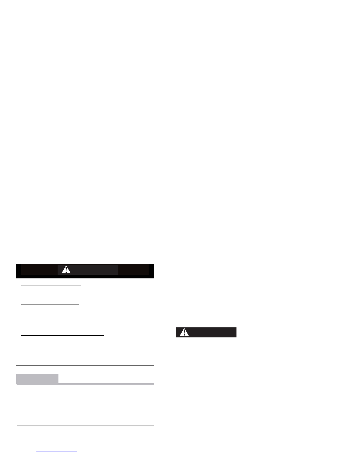
Messages with the Safety Alert Symbol
• Pay special attention to all messages preceded by the Safety Alert Symbol. It means ATTENTION! BECOME
ALERT! YOUR SAFETY IS INVOLVED.
CAUTION
Indicates a potential hazard which that could result in vehicle damage if instructions are not followed.
NOTE :
Provides helpful inform ation.
Indicates that severe personal injury or
death WILL result if instructions are not
followed.
Indicates a potential hazard that COULD
result in serious injury or death.
DANGER
WARNING

SPECIAL SAFETY MESSAGES
• AN ATV IS NOT A TOY AND CAN BE HAZARDOUS
TO OPERATE
• An ATV handles differently from other vehicles
including motorcycles and cars. A collision or
rollover can occur quickly, even during routine
maneuvers such as turning and driving on hills or
over obstacles, if you fail to take proper
precautions.
• Severe injury or Death can result if you do not
follow the se instructions:
• Read this manual and all labels carefully and
follow the operating procedures described.
• Never operate an ATV with out pr op er in structi on.
Take a training course. Beginners should receive
training from a certified instructor. Contact an
authorized ATV dealer or call 1-800-887-2887 (USA
only) to find out about the traini ng courses nea rest
you.
• Always follow the age recommendation: A child
under 16 years old should never operate an ATV
with engine size greater than 90cc.
• Never allow a child under age 16 to operate an A TV
without adult supervision, and never allow
continued use of an ATV by a child if he or she
does not have the abilities to operate it safely.
• Never carry a passenger on a ATV.
• Never operate an ATV on any paved surfaces,
including sidewalks, driveways, parking lots and
streets.
• Never operate an ATV on any public street, road or
highway, even a dirt or gravel one.
• Never operate an ATV without wearing an
approved motorcycle helmet that fits properly. You
should also wear eye protection (goggles or face
shield), glove s, boots , long-s lee ved sh irt or jac ket,
and long pants.
• Never consume alcohol or drugs before or while
operating this ATV.
• Never opera te at e xces sive sp eed s. Al ways go at a
speed that is proper for the terrain, visibility,
operating conditions, and your experience.
• Never attempt wheelies, jumps or other stunts.
• Always inspect your ATV each time you use it to
make sure it is in safe operating condition. Alw ays
follow the in spection and maint enance proc edures
and schedules described in this manual.
• Always keep both hands on the handlebars and
both feet on the footpegs of the ATV during
operation.
• Always go slowly and be extra careful when
operating on unfamiliar terrain. Always be alert to

changing terrain conditions when operating the
ATV.
• Never operate on excessively rough, slippery or
loose terrain until you have learned and practiced
the skills necessary to control the ATV on such
terrain. Always be especially cautious on thes e
kinds of terrain.
• Always f ollo w pr oper pro cedures f or turning a t low
speeds before attempting to turn at faster speeds.
Do not turn at excessive speed.
• Never operate the ATV on hills too steep for the
ATV or for your abilities. Practice on smaller hills
before attempting larger hills.
• Always f ollo w pr oper pr ocedu res f or climbin g hills
as described in this manual. Check the terrain
carefully before you start up any hill. Ne v er c l imb
hills with excessively slippery or loose surfaces.
Shift your weight forward. Never open the throttle
suddenly or make sudden gear changes. Never go
over the top of any hil l at high speed.
• Always follow proper procedures for going down
hills and for braking on hills as described in this
manual. Check the terrain carefully before you
start down any hill. Shift your weight backward.
Never go down a hill at high speed. Avoid going
down a hill at an angle that would cause the
vehicle to lean sharply to one side. Go straight
down the hill where possib le.
• Always follow proper procedures for crossing the
side of a hill as described in this manual. Avoid
hills with excessively slippery or loose surfaces.
Shift your weight to the uphill side of the ATV.
Never attempt to turn the ATV around on any hill
until you have mastered the turning technique
described in this manual. Avoid hills with
excessivel y slip pery or loose surfaces. Shift your
weight to the uphill side of the ATV. Never attempt
to turn the ATV around on any hill until you have
mastered the turning technique described in this
manual on le vel gr ound. Av oid cr ossing th e side of
a steep hill if possible.
• Always use proper procedures if you stall or roll
backwar ds when climbing a hill. To avoid stalling,
use the proper gear and maintain a steady speed
when climbing a hill. If you stall or r oll backwards,
follow the s pecial p r ocedu re f or braki ng descr ibed
in this manual.
• Always c heck for obstacles befor e opera ting in a
new area. Never attempt to operate over large
obstacles, such as large rocks or fallen trees.
Always follow proper procedures when operating
over obstacles as described in this manual.
• Always be careful when skidding or sliding. Learn
to safely control skidding or sliding by practicing
at low speeds and on level, smooth terrain. On
extremely s lippery surfaces, s uch as ice, go s lowl y

an be very cautious in order to reduce the chance
of skidding out of control.
• Never operate an ATV in fast flowing water or in
water deeper than that specified in this manual.
Remember that wet brakes may have reduced
stopping ability. Test you brakes after leaving
water. if necessary, apply them several times to let
friction dry out the linings.
• Always use the size and type of tires specified in
this manual. Always maintain proper tire pressure
as described in this manual.
• Never modify an ATV through improper installat ion
or use of accessories.
• Never install a twist grip throttle on this ATV.
• Never exceed the sta ted load limits for an ATV.
Cargo should be pro perl y distrib uted and secure ly
attached. Reduce speed and follow instructions in
this manual for carrying cargo. Allow greater
distance for braking.
• FOR MORE INFORMATION ABOUT ATV SAFETY,
call the Consumer Product Safety Commission at
1-800-638-2772, or the
ATV Distributors’ Safety Hotline
at 1-800-852-5344 (USA only).

CONTENTS
ATV SPORT REALITY - - - - - - - - - - - - - - 1
FOREWORD- - - - - - - - - - - - - - - - - - - 2
SAFETY ALERTS - - - - - - - - - - - - - - - - 4
SPECIAL SAFETY MESSAGES - - - - - - - - - 5
CONTENTS - - - - - - - - - - - - - - - - - - - 8
WARNING LABELS - - - - - - - - - - - - - - 10
MACHINE IDENTIFICATION - - - - - - - - - - 14
Vehicle Identification Number (VIN) - - - - - - - - 14
Engine Serial Number- - - - - - - - - - - - - - - 15
Key ID Number - - - - - - - - - - - - - - - - - - 15
PARTS AND CONTROL FUNCTIONS - - - - - 16
Owner’s Manual- - - - - - - - - - - - - - - - - - 18
Seat - - - - - - - - - - - - - - - - - - - - - - - 18
Ignition Switch- - - - - - - - - - - - - - - - - - - 21
Tether Switch - - - - - - - - - - - - - - - - - - - 22
Engine Stop/Start Buttons (MC500) - - - - - - - - 23
Engine Stop Switch/ Start Button (MC1000) - - - - 24
Headlights - - - - - - - - - - - - - - - - - - - - 25
Taillight - - - - - - - - - - - - - - - - - - - - - - 25
Front Brake Lever - - - - - - - - - - - - - - - - - 26
Parking Brake - - - - - - - - - - - - - - - - - - - 26
Rear Brake Pedal - - - - - - - - - - - - - - - - - 28
Footpegs & Baskets - - - - - - - - - - - - - - - - 28
Nerf Bars - - - - - - - - - - - - - - - - - - - - - 29
Shift Lever- - - - - - - - - - - - - - - - - - - - - 30
Fuel Tank Cap- - - - - - - - - - - - - - - - - - - 30
Handle Grips - - - - - - - - - - - - - - - - - - - 31
Throttle Lever - - - - - - - - - - - - - - - - - - - 32
Clutch lever (manual) - - - - - - - - - - - - - - - 33
Clutch lever (hydraulic) - - - - - - - - - - - - - - 33
Fuse & Diagnostics Connector - - - - - - - - - - - 34
Safety Flag Mount - - - - - - - - - - - - - - - - - 35
SAFE OPERATION- - - - - - - - - - - - - - - 36
Experienced Riders Only! - - - - - - - - - - - - - 36
Training and Instruction - - - - - - - - - - - - - - 37
Age Recommendation - - - - - - - - - - - - - - - 38
Wear Protective Gear - - - - - - - - - - - - - - - 39
Ride Sensibly - - - - - - - - - - - - - - - - - - - 40
No Passengers: No Exceptions! - - - - - - - - - - 41
Cargo, Loading Limit- - - - - - - - - - - - - - - - 42
Off-road Use Only - - - - - - - - - - - - - - - - - 43
Stay Off Public Roads and Highways- - - - - - - - 44
Turning The ATV - - - - - - - - - - - - - - - - - 45
Don’t Drink and Drive! - - - - - - - - - - - - - - - 46
No Wheelies, Stunts, or Jumps- - - - - - - - - - - 47
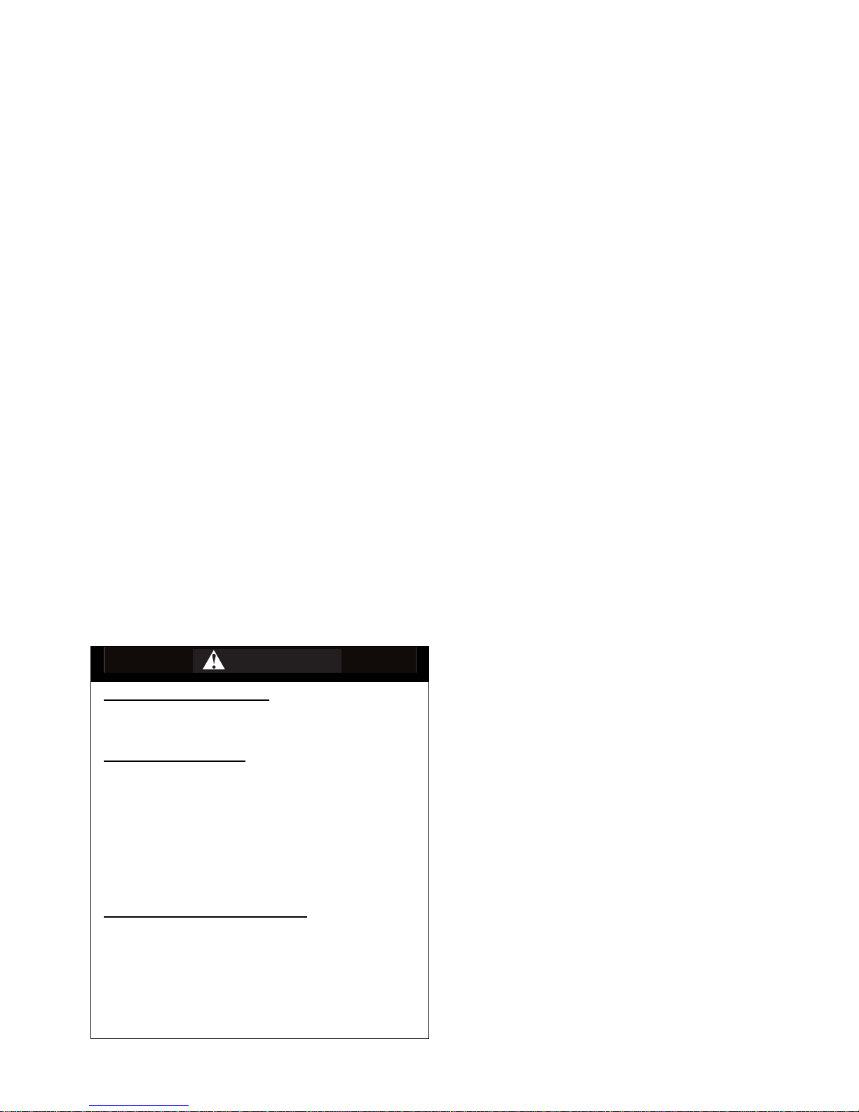
WARNING
Indicates a potential hazard
that COULD result in serious
injury or death.
When reading this manual, remember:

Keep Your Hands and Feet on the Controls- - - - 48
Watch Out for Terrain Changes- - - - - - - - - - 49
Rough or Slippery Terrain - - - - - - - - - - - - 50
Stay Off Steep Hills- - - - - - - - - - - - - - - - 51
Climbing Hills Improperly - - - - - - - - - - - - - 52
Riding downhill - - - - - - - - - - - - - - - - - - 53
Crossing Slopes or Hills - - - - - - - - - - - - - 54
Turning on Slopes or Hills - - - - - - - - - - - - 55
Obstacles - - - - - - - - - - - - - - - - - - - - 56
Skidding or Sliding - - - - - - - - - - - - - - - - 57
Safety Flag- - - - - - - - - - - - - - - - - - - - 58
Riding Through Shallow Water - - - - - - - - - - 59
Stalling, Rolling Backwards- - - - - - - - - - - - 60
Modifications- - - - - - - - - - - - - - - - - - - 61
PRE-RIDE INSPECTION- - - - - - - - - - - - 62
Pre-Ride Checklist - - - - - - - - - - - - - - - - 63
OPERATION- - - - - - - - - - - - - - - - - - 64
BREAK-IN - - - - - - - - - - - - - - - - - - - 67
MAINTENANCE & ADJUSTMENT - - - - - - - 68
Work safely - - - - - - - - - - - - - - - - - - - 68
Maintenance Schedule - - - - - - - - - - - - - - 72
Panels - - - - - - - - - - - - - - - - - - - - - - 75
Frame, Subframe, Swingarm - - - - - - - - - - - 80
Fuel - - - - - - - - - - - - - - - - - - - - - - - 82
Engine Oil - - - - - - - - - - - - - - - - - - - - 85
Transmission Oil - - - - - - - - - - - - - - - - - 91
Coolant - - - - - - - - - - - - - - - - - - - - - 95
Brakes - - - - - - - - - - - - - - - - - - - - - 100
Clutch - - - - - - - - - - - - - - - - - - - - - 109
Drive - - - - - - - - - - - - - - - - - - - - - - 116
Electrical - - - - - - - - - - - - - - - - - - - - 123
Air - - - - - - - - - - - - - - - - - - - - - - - 136
Exhaust - - - - - - - - - - - - - - - - - - - - 139
Suspension- - - - - - - - - - - - - - - - - - - 140
Wheels- - - - - - - - - - - - - - - - - - - - - 146
Tires - - - - - - - - - - - - - - - - - - - - - - 149
CLEANING- - - - - - - - - - - - - - - - - - -152
STORAGE - - - - - - - - - - - - - - - - - - -153
TRANSPORTING - - - - - - - - - - - - - - -154
TORQUE TABLE- - - - - - - - - - - - - - - -156
TROUBLESHOOTING - - - - - - - - - - - - -157
MAINTENANCE RECORD- - - - - - - - - - -160
2002 MODEL SPECIFICATIONS- - - - - - - -161
Engine - - - - - - - - - - - - - - - - - - - - - 161
Chassis - - - - - - - - - - - - - - - - - - - - 164
Suspension- - - - - - - - - - - - - - - - - - - 166
ATV LIMITED WARRANTY - - - - - - - - - -168
STOLEN UNITS - - - - - - - - - - - - - - - -169
CHANGE OF ADDRESS - - - - - - - - - - - -169
ADDENDA - - - - - - - - - - - - - - - - - - -170
WARNING LABELS
Examples of all vehicle w arni ng labels are found in thi s
section. Read and understand the actual ones on your
vehicle. The labels contain i nfor mation which is important
to your safety and that of anyone else who operates the
ATV.
• The warning labels should be considered
permanent parts of vehicle. Yes, just like the
wheels and engine, they are needed parts for any
operator.
• If any label is missing, worn, damaged, or
becomes unreadable, be sure to replace it.
Cannondale offers replacement labels at no
charge. A label’s part number is printe d in the
lower right corner of the label and here in the
manual. Contact an authorized Cannondale
motorsports dealer for replacements.
• Label locations are shown in the following
illustration. Examples of the labels are shown on
the following pages.
• Always replace labels in the correct position. See
the illustration for the correct location of the
warning labels on your vehicle.
(1)
(2)
(3)
(4)
(5)
(6)
(7)
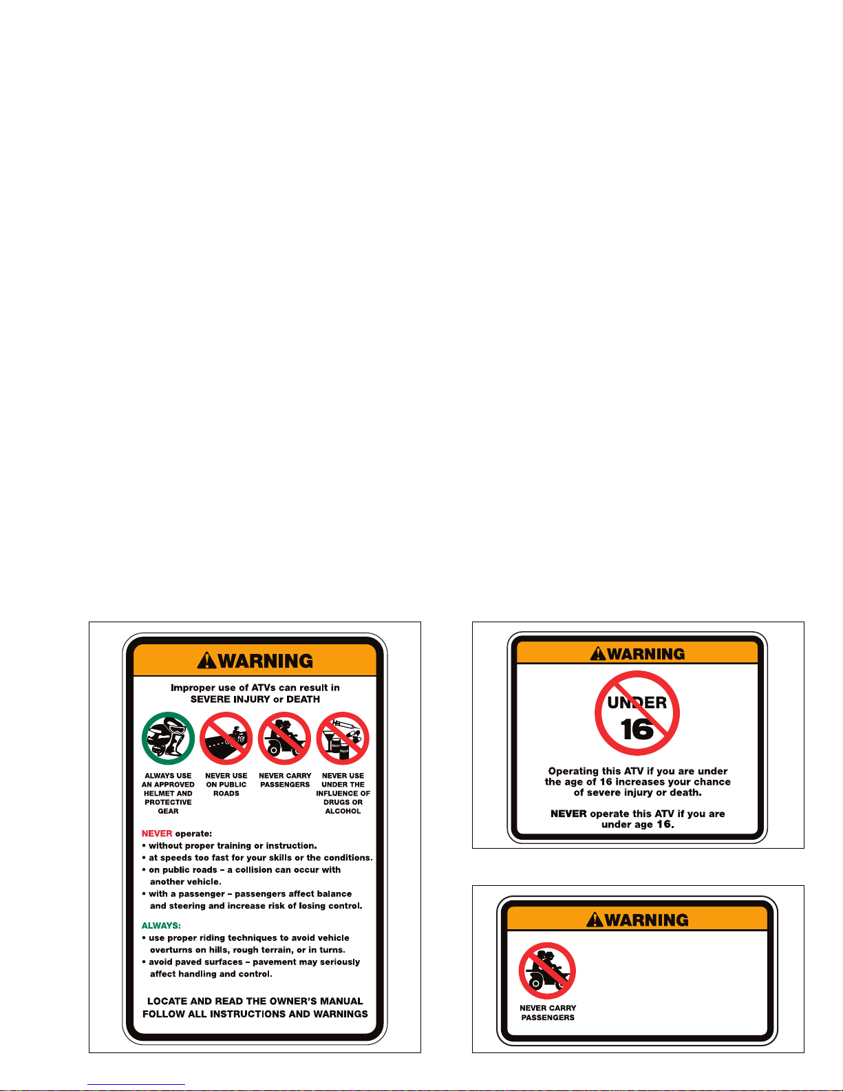
Label 2 P/N 315-6000236-01
315-6000236-01
Label 2 P/N 315-6000237-01
Label 3 P/N 315-6000239-01
315-6000237-01
Riding as a passenger can cause
the ATV to go out of control.
Loss of control can cause a
collision or rollover, which can
result in severe injury or death.
NEVER ride as a passenger.
315-6000239-01

Label 4 P/N 315-6000238-01
Label 5 P/N 315-6000477-01
315-6000238-01
315-6000477-01
Label 6 P/N 315-6000580-01
315-6000580-01
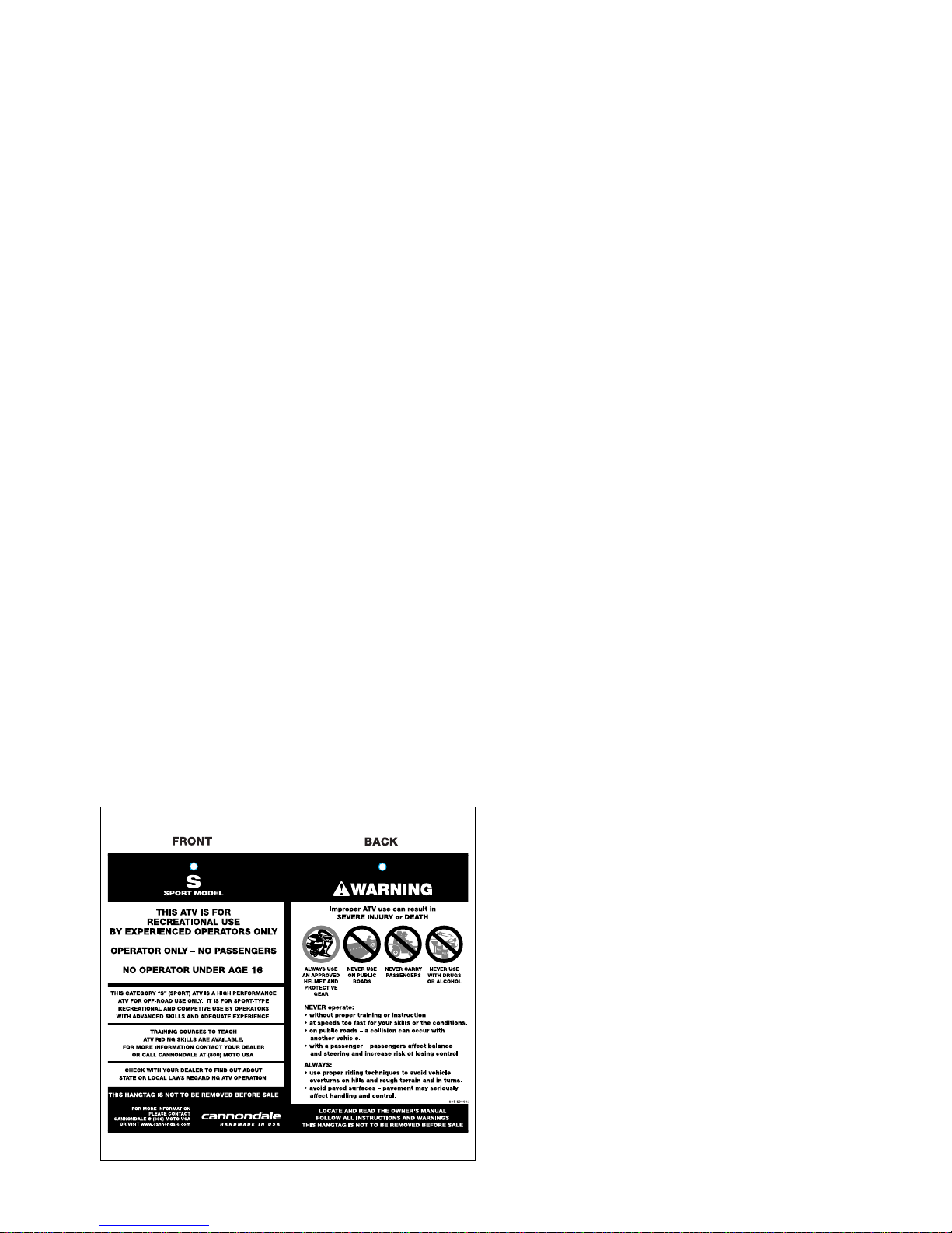
Hangtag
All Cannondale ATVs are ship ped w ith a r em ova ble
hangtag attached to the handlebar. Like the vehicle’s
warning labels, this hangtag contains important information
for your safety. Read and understand it throroughly before
removing it.
MACHINE IDENTIFICATION
NOTE :
Your vehicle may differ from those shown in the
illustrations in this manual.
Record your vehicle’ s identification num be rs in the
spaces provided. Keep another record of the numbers in a
safe place; you may need the m for parts , serv ic e
information, or theft recovery.
Your vehicle’s ID numbers identify it from others of the
same model type.
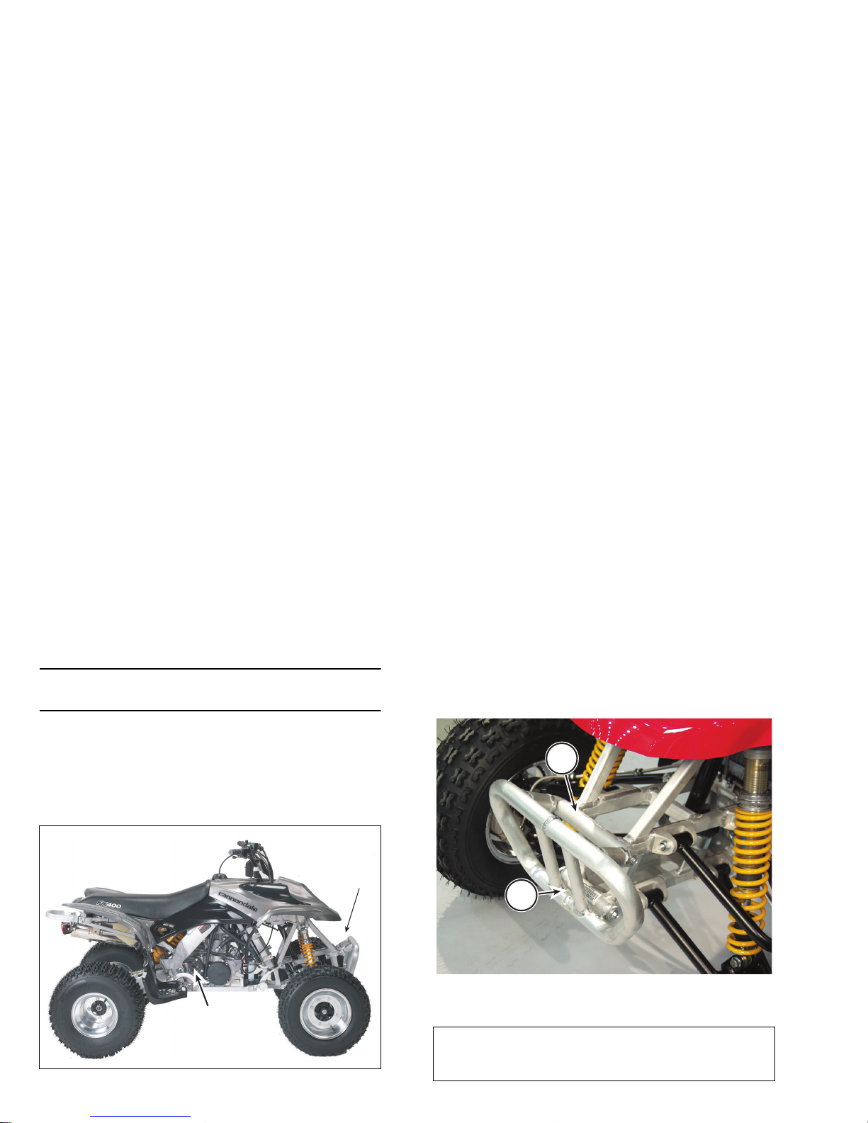
VEHICLE IDENTIFICATION NUMBER (VIN)
The vehicle identification number (VIN) is etched/
stamped into the frame behind the fron t brush gu ard. The
VIN also appears on a temporary factory applied adhesive
label in the same area.
1. Vehicle identification number (VIN)
2. Engine serial number
(1)
(2)
1. Etched vehicle identification number
2. Factory VIN label
Write your number here
1
2
ENGINE SERIAL NUMBER
The engine serial nu mber is etched/stamped into th e
rear area of the engine crankcase. The nu mb er also
appears on a metalli c pla te affixed to the crank case area
above the countersha ft sprocket. The number al so appears
on a temporary factory applied adhesive label in the same
area.
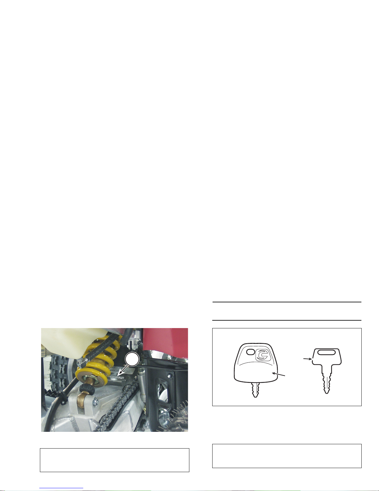
KEY ID NUMBER
Key identification numbers are etched/stamped into key
bodies.
NOTE :
Keep your spare key in a safe place in case you lose
the primary key.
1. Engine serial number
Write your number here
1
1. Primary Key (remove housing to view ID number)
2. Spare key
3. Key ID number
4. Housing
Write your number here
XXXXXX
(1)
(2)
(3)
(4)
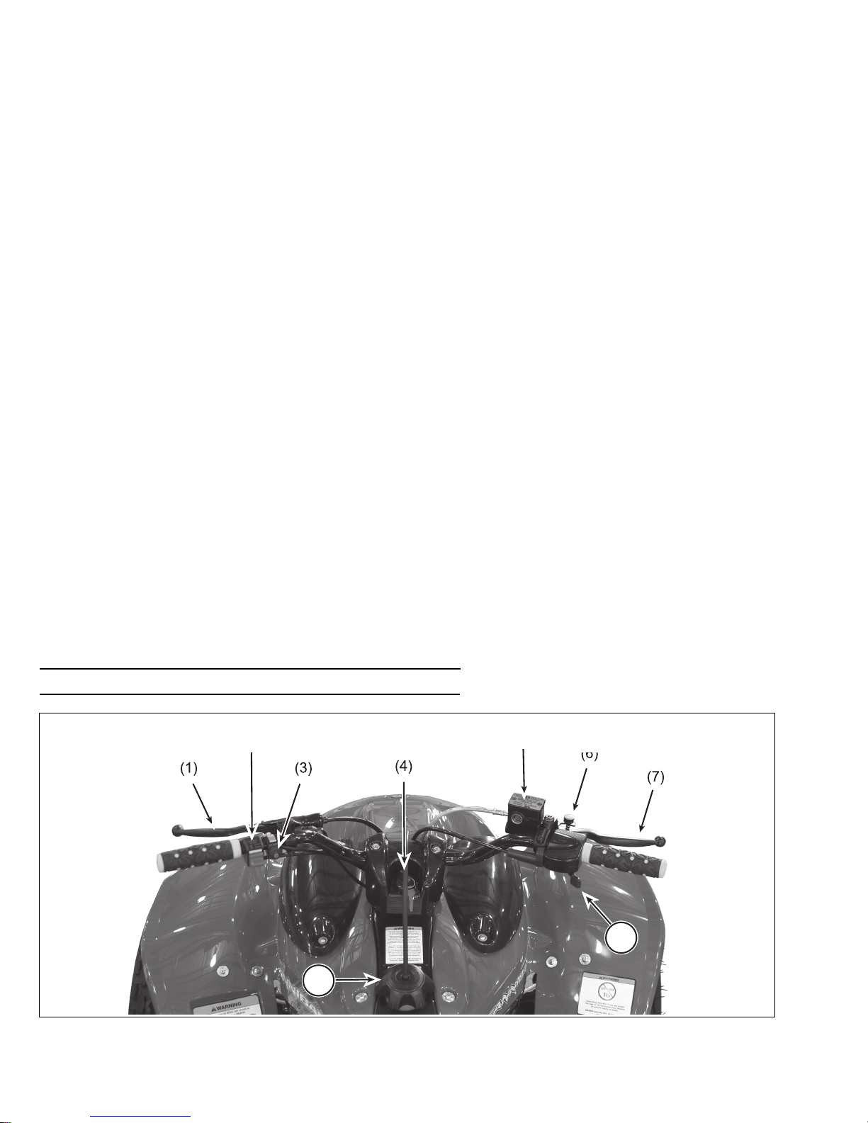
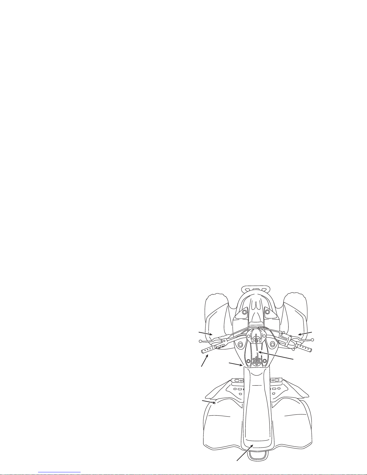
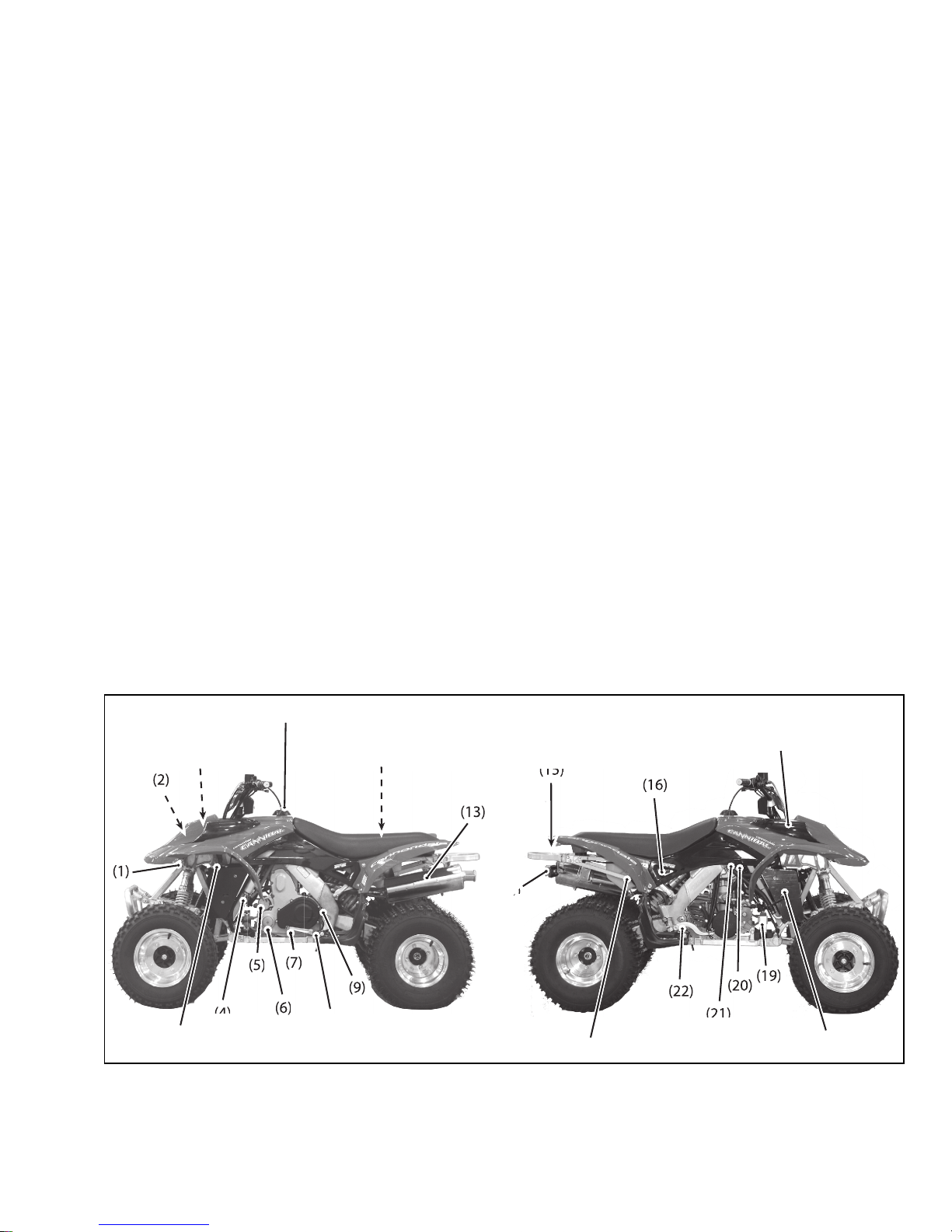
PARTS AND CONTROL FUNCTIONS
NOTE :
Your vehicle may differ slightly from those shown in the illustrations in this manual.
8
9
(2)
(5)
1. Clutch lever
2. Engine RUN/OFF switch
3. Engine start switch (green)
4. Ignition switch
5. Front brake master cylinder
6. Parking brake lock
7. Front brake lever
8. Throttle
9. Fuel cap
(12)
(11)
()
(3)
(4)
(8)
(10)
(14)4)4)
(3)
(18)
(17)
(21)
1. Rectifier/regulator
2. Engine Control Unit (ECU)
3. Diagnostic connector & fuse
4. Fuel pump
5. Starter
6. Engine oil filter (1 of 2)
7. Shift lever
8. Transmission oil level check
9. Left frame spar drain bolt
10. Air filter
11. Fuel cap
12. Owner’s Manual
13. Muffler
14. Taillight
15. Safety flag mount
16. Fuel filter
17. Engine oil, coolant levels check
18. Radiator
19. Battery
20. Coolant bleed bolt
21. Right frame spar drain
22. Rear brake pedal
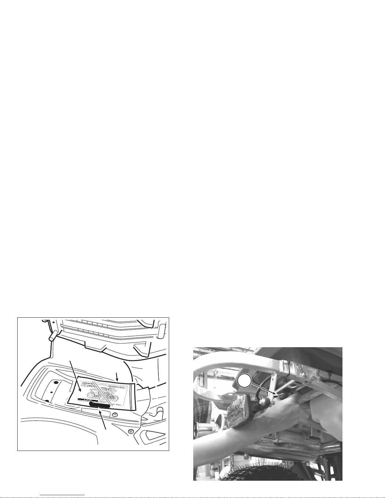
OWNER’S MANUAL
The Owner’s Manual for your vehicle is located under
the seat. It contains important safety and maintenance
information. Keep it on the vehicle when you ride. To find
the manual, remove the seat.
SEAT
The seat on your vehicle is for you only. Carrying a
passenger can cause you to lose control of the vehicle.
The entire length of the seat is required so that you can
shift body weight/position while riding to maintain vehicle
control and stabilit y. Make sure the seat is in good
condition and fasten ed securely before you ride.
1. To remove the seat, loosen and completely remove the
seat retention bolt.
1. Owner’s manual
2. Low pressure tire gauge
3. Vinyl bag
(2)
(1)
(3)
1. Seat retention bolt
b
a
1
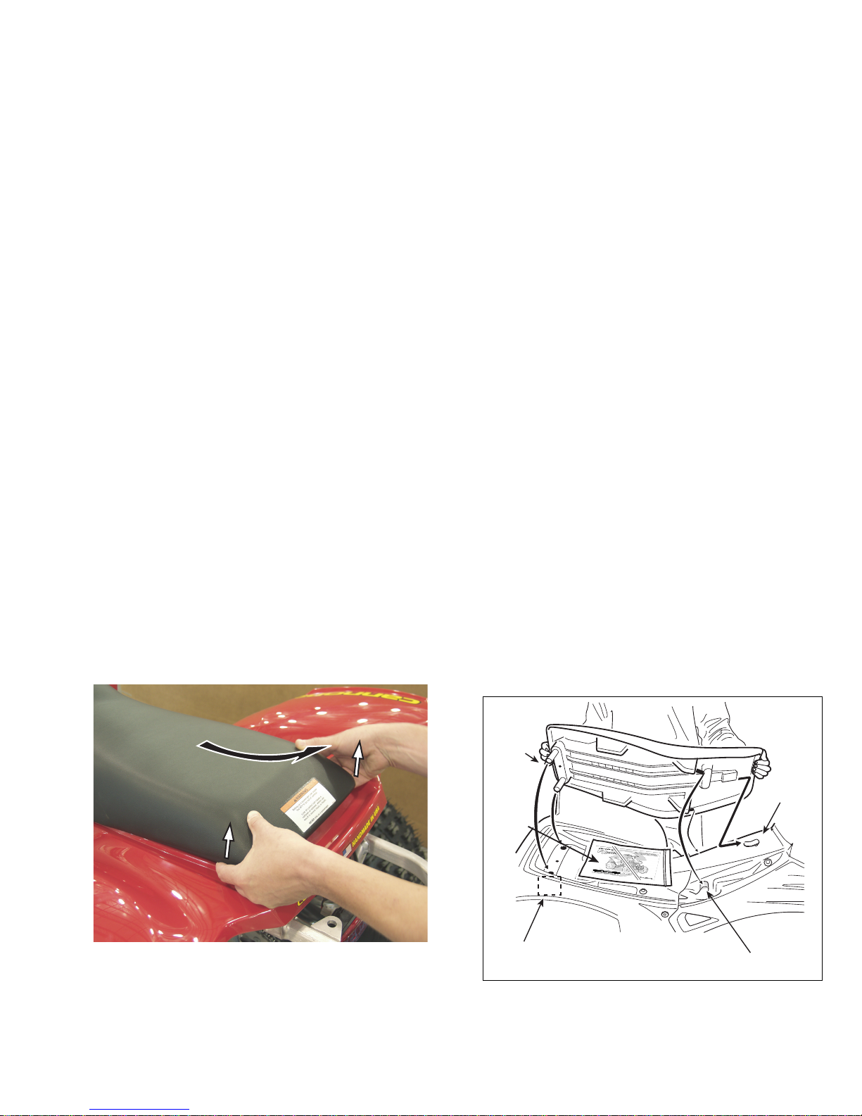
2. Use your fingertips to lift up the rear of the seat slightly.
Then, pull the seat back toward the rear of the vehicle
and lift it off.
3. To install the seat, align the receivers in the seat pan
with the fuel tank clip and the subframe guides.
4. Press down gently on the middle of the seat and slide
the seat forward onto the clip and subframe guides. If
correctly aligned, the rear seat pegs will slip easily
through the subframe seat buffers.
1. Fuel tank clip
2. Subframe guides (right)
3. Seat pegs
4. Subframe seat buffers (right)
5. Owner’s Manual & Tool Kit
(1)
(3)
(4)
(5)
(2)
CAUTION
Do not force the seat pegs through the holes in the
rear fende r o r sub f ra me buf f e rs; y ou c o ul d damag e
the seat.
Avoid excessive force.
5. Install the seat retention bolt and tighten it securely.
WARNING
POTENTIAL HAZARD
Loose, damaged, or improperly installed seat
WHAT CAN HAPPEN
The seat can shift or come off while you are riding
causing you to lose control of the vehicle. You can
be severely injured or killed.
HOW TO AVOID THE HAZARD
Always make sure the seat is locked into position
on the mounts and secured properly with the
retention bolt. Never ride this ATV with a damaged
seat. Have it replaced.
WARNING
Indicates a potential hazard
that COULD result in serious
injury or death.
When reading this manual, remember:
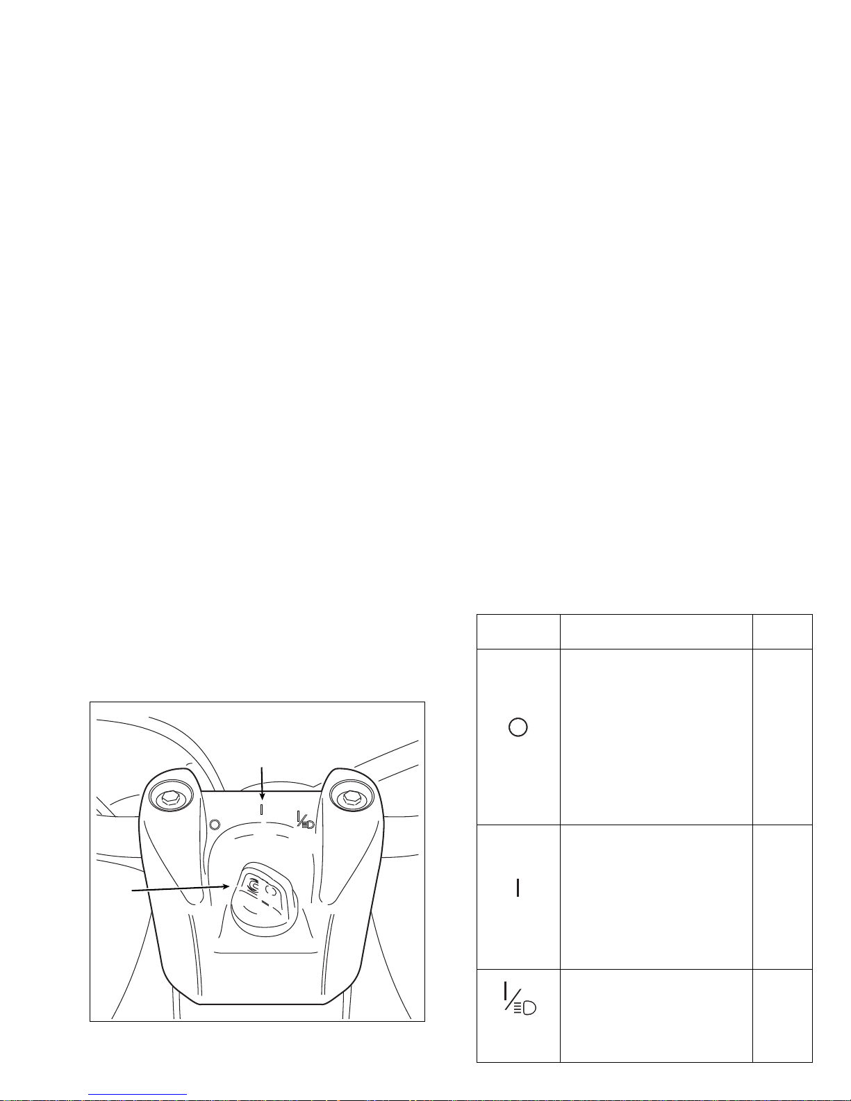
IGNITION SWITCH
The ignition switch is located between the handlebars.
Always remove the key from the swi tch to help prevent
unauthorized vehicle use or theft. See the table for a
descripti on of the switch positions.
1. Ignition switch (key shown inserted)
2. Switch positions
(1)
(2)
Key Position Function
Key
Removal
“OFF”
The engine and lighting
cannot be operated.
Turning th e igni tion switch to
the “OFF” position, will stop a
running engine, however, we
recommend using the engine
stop button (or switch) as the
primary me ans to shut off a
running engine - follow-up by
turning the switch to the “OFF”
position.
Yes
“ON”
With the Engine Stop switch
in the “RUN” position and the
clutch lever pulled in, the e ngi ne
can be started using the Engine
Start button.
We recommend starting the
engine with the ig nition switch in
the (I) position then switch to t he
“ON w/LIGHTS” position
No
“ON w/
LIGHTS”
Lighting (headlights and
taillight are activated.
No
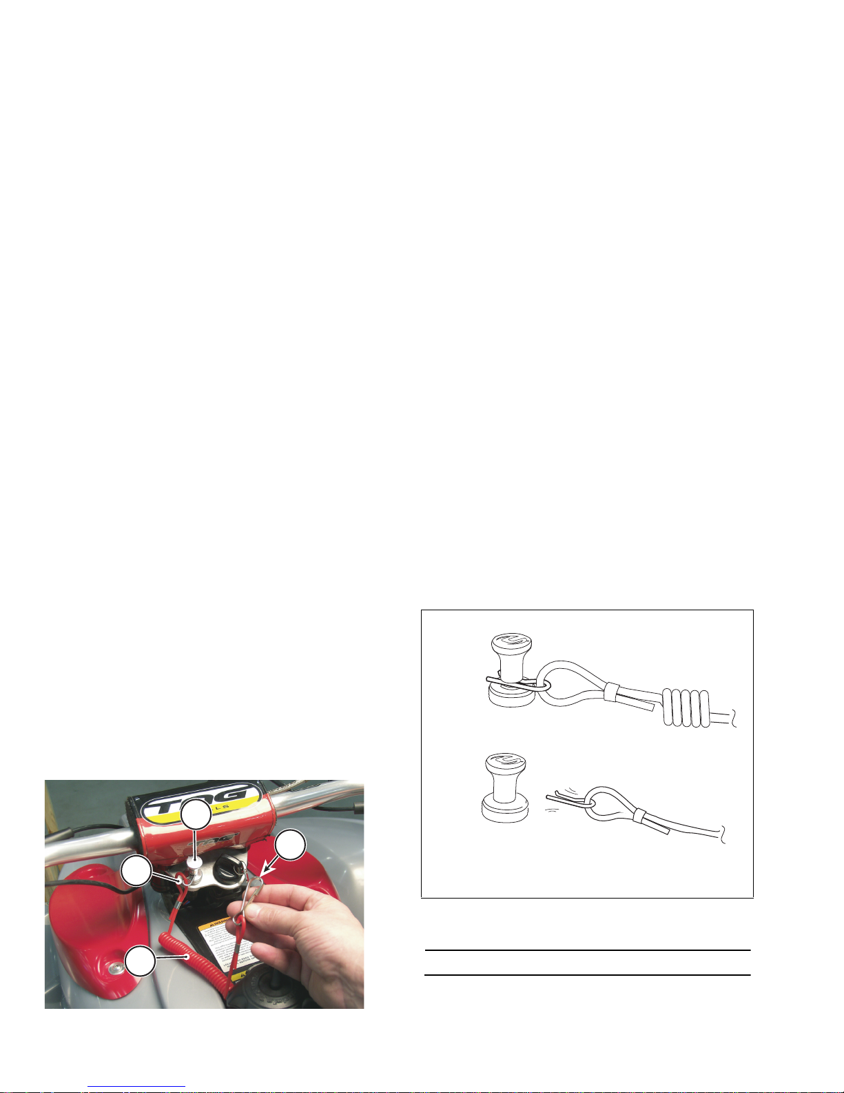
TETHER SWITCH
On equipped models, the tether switch is an additional
safety device. Test for proper operation of the switc h before
riding. The switch mus t be i n the operating position to start
the vehicle. To test the switch, ma ke sure the switch pin is
inserted correctly. Start the engine. With the engine
running, pull the strap quic kly from the switch body the
engine should shut down imme diatel y. If it does not, do not
ride the ATV ; the switch is damaged and must be replaced.
Contact your dealer for a replacement.
1. Switch body
2. Tether pin
3. Tether strap
4. Body clip (to be secured to the rider)
1
3
2
4
1. Tether switch in operate position
2. Detached position
NOTE :
Body clip attachment to rider not illustrated.
(1)
(2)
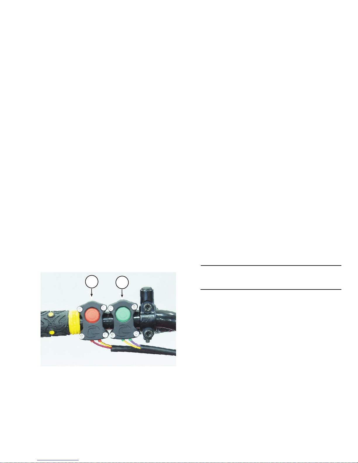
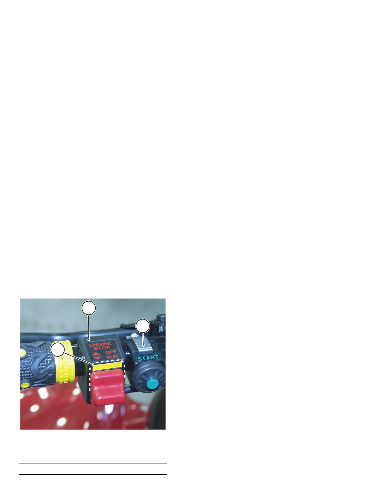
ENGINE STOP/START BUTTONS (MC500)
Engine stop button
The engine st op button is located on the left handlebar
close to the inside edge of the handle grip and is red in
color. Press the stop button to shut off the running engine.
It is also an emergency con trol. Test the stop button before
moving off to ride to confirm that it is operating properly. If
the switch does not “kill” the engine, don’t ride the ATV.
Turn the i gn itio n s witc h to the “OFF” position and contact a
Cannondale motorsports dealer to have it replaced.
NOTE :
The stop button is a “normally closed” circuit switch. If
the switch is damaged or the wires are frayed or torn,
(i.e. circuit open) the engine will not start.
Engine start button
The engine start button is green in c ol or a nd is mounted
closer to the center of the handleb ars. Pressin g it activ ates
the engine management syste m ci rcui ts and the starter
motor. Make sure it operates properly before each ride.
1. Engine stop button
2. Engine start button
1
2
ENGINE STOP SWITCH/ START BUTTON
(MC1000)
Engine stop switch
The engine stop switch is located on the left handlebar
close to the inside ed ge of the han dle grip and is the sli ding
type with two positions. Sliding the switch to the “OFF”
position will deactivate the Engine Management System
and is the recomm ended me thod to stop the engin e while it
is running as opposed to using the ign iti on switc h. This
switch is also an e m ergency contr ol used to shut down the
engine quickly with your thumb without removing your
hands from the handle grip. This switch must be
maintained nearer the handle grip for this reason. During
your pre-ride inspection an d before mo ving of f to ride, start
the engine and tes t the s witch to confi rm that i t is o peratin g
properly. If the sw itch d oes not “kill” a running en gine, don’t
ride the ATV. Remove the key from the ignition switch to
prevent vehicle use and contact an Cannondale
motorsports dealer for servicing.
Engine start button
The engine start button is green in c ol or a nd is mounted
closer to the center of the handleb ars. Pressin g it activ ates
the engine management syste m ci rcui ts and the starter
motor. Make sure it operates properly before each ride.
1. Engine OFF/RUN Switch
2. Engine start button
a. OFF posi tion
NOTE :
The switch is sh own in the R UN position in this photo.
1
2
a
1
2
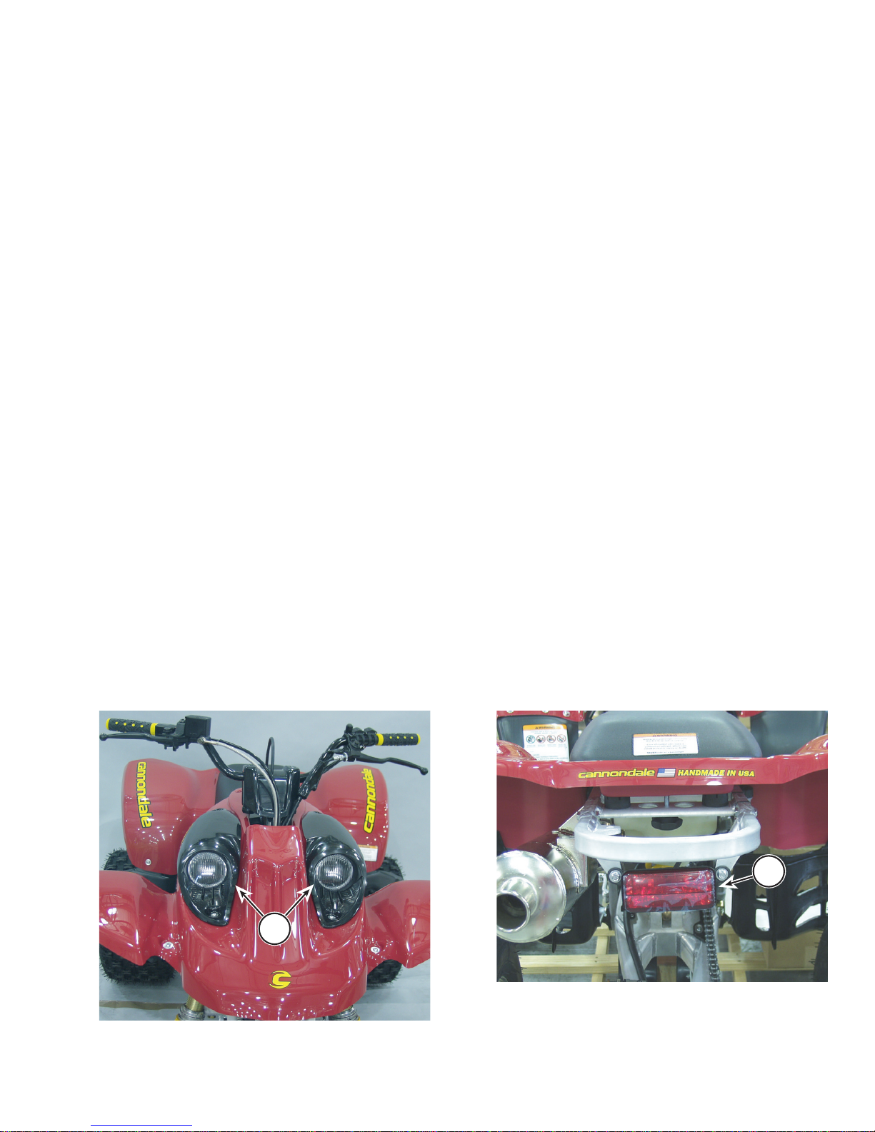
HEADLIGHTS
Turn the ignition switch to the “ON w/LIGHTS” position
to activate the headlights. Test for the proper operation of
the headlights before op erating the vehicle .
TAILLIGHT
Turn th e ignition swi tch to the “ON with LIGHT S” positio n
to activate the taill ight. The taillight IS NOT a brake light.
Make sure it works before every ride.
1. Headlights
1
1. Taillight
1
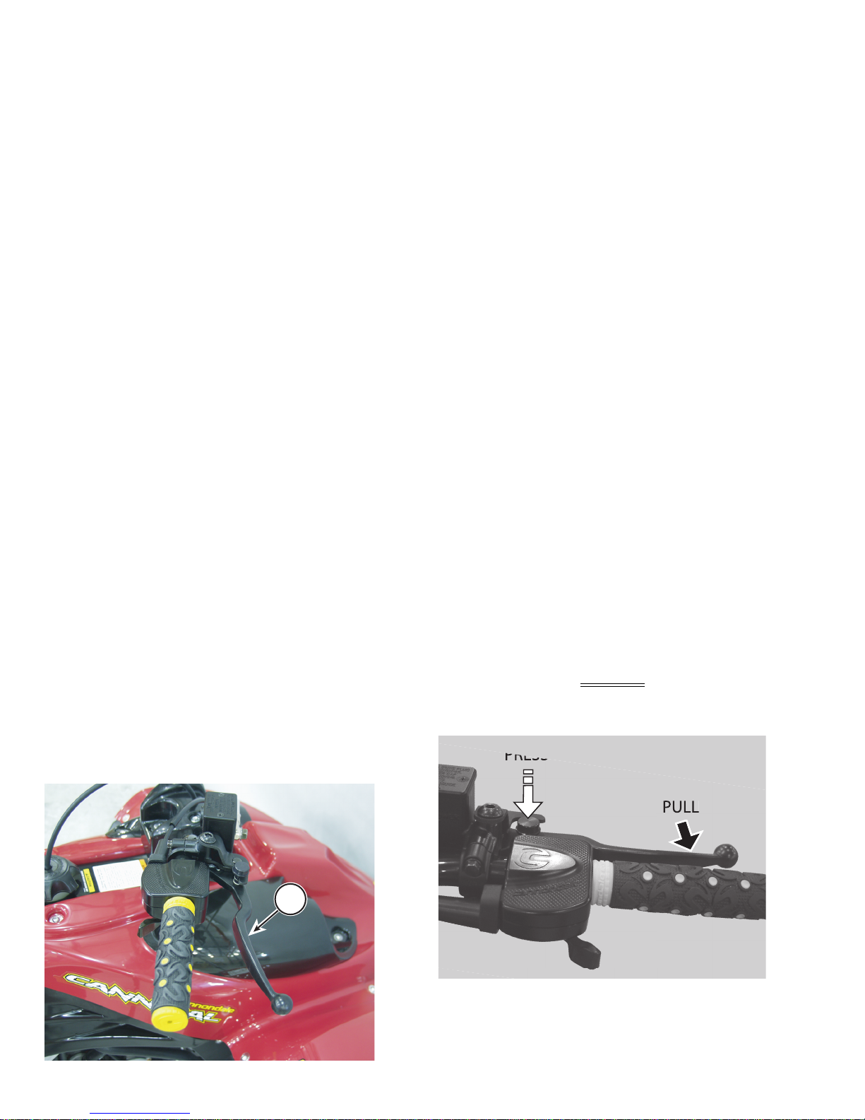
FRONT BRAKE LEVER
The front brake lever is located on the right side of the
handlebar. Pull it toward the handlebar to apply the front
brakes. Pull the lever harder to increase braking force.
Before each ride, make sure the front brake s are
operating properly and can provide braking force when
needed. Roll the v ehi cl e forw ard and back applying the
brake to confirm that brak ing force is applied to the front
brake discs.
PARKING BRAKE
The parking brake is applied with a lock button on the
front brake lever. When the parking brake is applied
(locked), the front brakes temporarily
prevent the vehicle
from rolling. Be sure to read the warning about using the
parking brake!
1. Front brake lever
Front brake lever view
1
1. To apply, pull the front brake lever against the handle
grip and hold it. Press and hold the locking button with
your index finger until it is fully depressed - release the
lever and remove your index finger from the button.
2. To disengage the parking br ak e , pr ess d own on the re ar
brake pedal with your foot. Then, pull the front brake
lever against the handle grip; the locking mechanism
will automatically disengage (pop up).
3. Release the front bra ke lever slowly.
WARNING
POTENTIAL HAZARD(S)
(1) ATV rolling away
(2) Riding with the parking brake applied
WHAT CAN HAPPEN
(1) A potential decline in fluid pressure can
decrease the applied braking force allowing the
ATV to begin to roll.
(2) Brake system will overheat, cause premature
wear, and damage to the brake pads. This can
result in a loss of brake function.
In either case above, severe injury or death can
result to the owner or bystanders.
HOW TO AVOID THE HAZARD
(1) Always block or chock the wheels on your ATV
immediately after applying the parking brake.
Never apply the parking brake and leave the
vehicle unattended.
Always choose firm level ground on which to park
your ATV.
(2) Release the parking brake before you ride.
REAR BRAKE PEDAL
The rear brake pedal is located on the rig ht sid e of the
vehicle. When pressed, braking forc e is app li ed to the rea r
wheels. Make sure the rear brake is operating properly
before you ride. Roll the vehicle forward and back and
press the pedal to confirm that braking force is applied to
the rear brake disc.
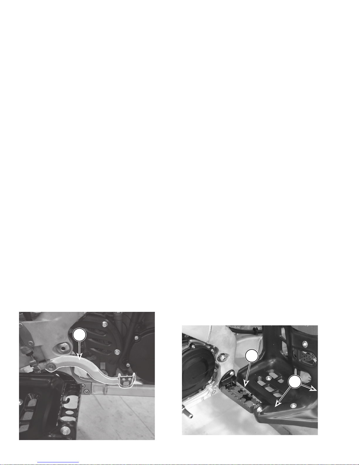
FOOTPEGS & BASKETS
When riding always keep your feet on the footpegs.
Always check the condition of the footpegs and baskets
before every ride. Make sure that they are fastened
securely to the vehicle. The footpeg teeth should be in
good condition (not smooth or wo rn exc es si ve ly) . The
baskets should be free of an y packed soils an d they sh ould
not be cracked, broken, or dam aged in any way. If damage
is found install new ones.
1. Rear brake pedal
1
1. Footpeg (left)
2. Basket
1
2
 Loading...