

Page 1
Cannon
INSTALLATION INSTRUCTIONS
Gmk10025
AS4553:2008
Please leave instructions with the owner
Pa rt No : F377 1
Revision A - 2010
Cannon
For service to this appliance or spare
parts contact the CANNON distributor:
email: service@sampfordixl.com.au
Phone: 1300 727 421
Fax: 1300 727 425
PLEASE READ THIS MANUAL
BEFORE INSTALLING AND
USING THIS PRODUCT.
DON’T RISK YOUR
APPLIANCE WARRANTY
ONLY A LICENSED PERSON
WILL GIVE YOU A
COMPLIANCE CERTIFICATE,
SHOWING THAT THE WORK
COMPLIES WITH ALL THE
RELEVANT STANDARDS.
AND ONLY A LICENSED
PERSON WILL HAVE
INSURANCE PROTECTING
THEIR WORKMANSHIP FOR 6
YEARS.
SO MAKE SURE YOU USE A
LICENSED PERSON TO
INSTALL THIS APPLIANCE
AND ASK FOR YOUR
COMPLIANCE CERTIFICATE
TO ENSURE THE
MANUFACTURERS
APPLIANCE WARRANTY WILL
BE HONOURED.
Date installed: ...............................................................................................
Compliance Certificate No .............................................................................
Installed by: ...................................................................................................
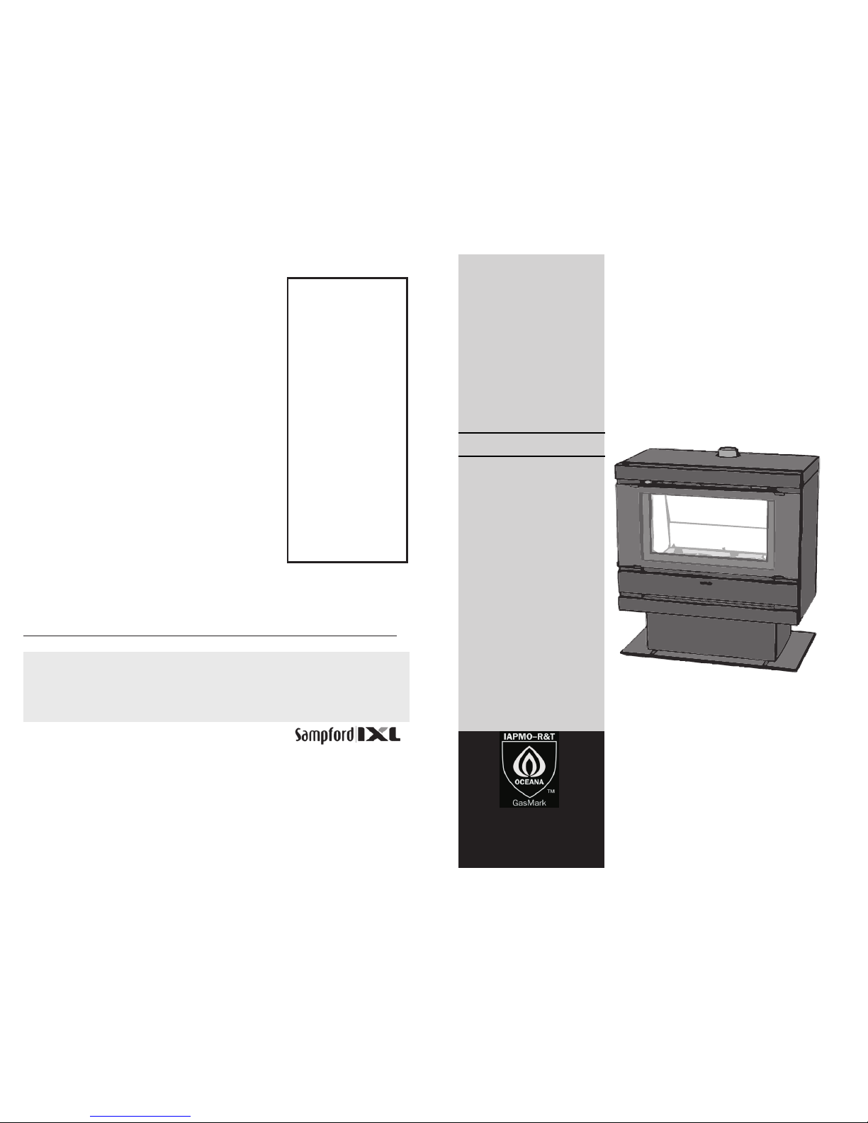
Freestanding kit
to suit
Fitzroy Inbuilt heaters
Freestanding kit
Should you require assistance or further information please contact your Cannon distributor.
Read these instructions in conjunction
with heater installation instructions
Page 2

Figure 9
Figure 9 shows Flue system in position. For more detail, refer to heater
installation booklet supplied with heater or contact Sampford IXL (contact details on
the rear of this booklet).
25 mm MINIMUM CLEARANCE
TO COMBUSTIBLE MATERIAL
MAINTAIN 25 mm MINIMUM
CLEARANCE BETWEEN FLUE
AND COMBUSTIBLE
MATERIALS.
500 mm
MINIMUM
125 mm FLUE COWL
APPROVED TO AG 604
IF THE COUPLING IS ABOVE
ROOF LEVEL SEAL JOINT
WITH SILICONE TO PREVENT
WATER INGRESSION
FLASHING TO PROVIDE A
WATERTIGHT SEAL
CEILING RING
FLUE SPIGOT ADAPTER
UPPER LENGTH FITS INSIDE
LOWER LENGTH. RIVET FLUE
JOINS.
RIVET 6 PLACES EACH JOIN
NOTE:
FIT A MINIMUM OF TWO LENGTHS
(1.74 M) OF VERTICAL FLUE
BEFORE FITTING ANY 45° BENDS.
IF BENDS ARE USED, THEY MUST
FIT INSIDE THE FLUE ON
DOWNWARDS ENDS.
USE NO MORE THAN TWO 45°
BENDS IN THE TOTAL FLUE RUN
AND MAINTAIN AT LEAST 250 mm
OF STRAIGHT FLUE PIPE
BETWEEN THE BENDS.
125 mm DIA
FLUE PIPE.
Contents
1
6
Mounting heater in freestanding body
Pg 2-4
Minimum clearances
Pg 4
Gas and Electrical connections
Pg 4
Flue installation
Pg 5-6
Page 3

2
5
Mounting heater in freestanding body
1. Remove cross brace on freestanding
body (keep screws).
2. Remove components packaged within for
transport (These components are
wrapped for protection).
3. Reach down into the base of the pedestal
and unscrew the transit screws holding
the freestanding body to the pallet.
4. Position the heater near installation area.
5. Locate the internal ducting
assembly amongst the components
removed from inside the
freestanding body (Figure 2).
6. Remove the rear inspection cover,
gaskets and flue spigot from the
internal ducting assembly (keep
screws).
This Flue and Cowl system shall be installed only by an authorised person and in
accordance with the manufacturers installations (below), local gas fitting regulations,
municipal building codes, AS 5601 Gas Installations and any other statutory
regulations.
METHOD
1. Inspect Flue components for any obvious damage.
2. Position heater in final position and prepare ceiling and roof cutout positions
using a string line from heater flue outlet. See Figure 9. Ensure that the ceiling
ring clears the cornice once installed, similarly a notch can be made in the
cornice as long as clearances to combustible materials are maintained.
3. Fit flue adaptor into heater flue outlet.
4. Install flue lengths in turn, fitting upper flue length inside the lower flue length.
Secure each join with three rivets.
5. Fit ceiling ring over flue at appropriate time, secure to ceiling by bending tabs
over ceiling material.
6. Slide the Flue Cowl over the outside of a 125mm diameter flue. Do not insert
Flue Cowl past the swage point. Ensure a min of 500mm distance from cowl to
roof surface. See Figure 8.
7. Install suitable flashing at roof junction to provide watertight seal between flue
and roof surface. See Figure 9.
8. Check flue system for alignment and that the Flue Cowl is venting normally.
Swage.
(Insert flue pipe
to this point only)
125mm Cowl
Rivet or Tek screw.
(3 places,
NOT supplied)
125 mm DIA
Flue pipe.
FIGURE 2.
Cowl installation.
Flue installation
Figure 1
Figure 2
Figure 8
Page 4

9. Screw four screws through inspection hole at the points shown to secure duct
(Figure 5).
10. Replace two screws removed in step 8 are now replaced to hold the duct.
3
4
7. Remove the two screws holding the flue flange on the back of the heater, and
take off the flange. Also remove two screws from the top panel of the heater
(Figure 3).
8. Attach the internal ducting assembly to the rear of the heater in the order shown in
Figure 4. Make sure that the gaskets are in place and secured appropriately.
11. Lift and slide heater into the freestanding
body (Figure 6).
12. Secure the heater by screwing the four
retaining screws through the front flange
and into the freestanding body. Re-attach
the flue spigot using the same three screws
that were previously removed.
13. Position the heater in the desired
position making sure to leave at least
minimum clearances as shown in
Figure 7.
Gas and Electrical connections
Refer to the heater installation instructions for gas and electrical connections.
A hole can be made in the floor directly under the heater for gas connection.
Similarly an electrical connection can also be made within the pedestal. Ensure that
hardwired units have an appropriate isolation switch. If a unit is connected through a
powerpoint ensure that the switch is in an accessible position.
Figure 3
Figure 4
Figure 5
Figure 6
Figure 7
 Loading...