

Page 1
HOBS
USER INSTRUCTIONS
KOOKPLATEN
GEBRUIKSAANWIJZING
ENCIMERAS
INSTRUCCIONES PARA EL USO
EN
NL
ES
Page 2
2
VERY IMPORTANT - APPLYING THE SEALANT
Important - The diagram below shows how the sealant should be applied.
1
INSTALLATION
The Purchaser is responsible for the installation of the hob. The Manufacturer does not
accept any responsibility for any damage or loss resulting from incorrect installation,
and as such this will not covered by the Manufacturer’s Guarantee.
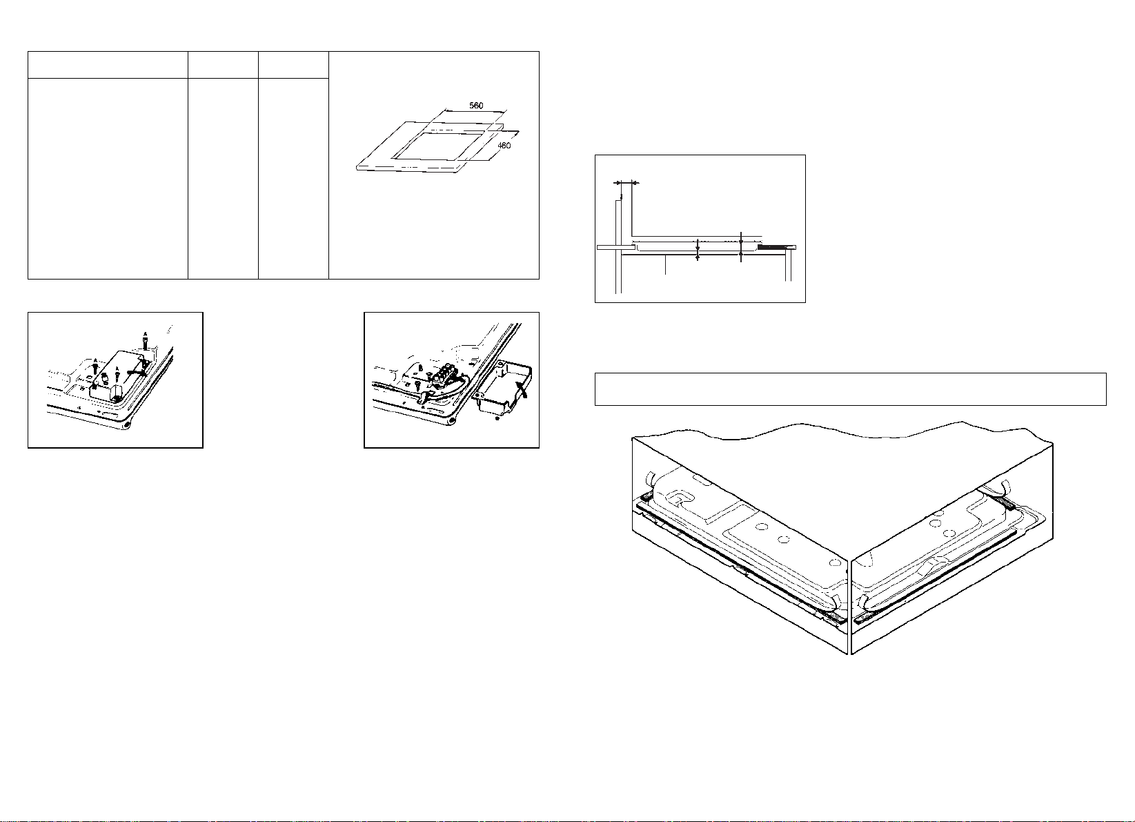
The hob may be installed in any worktop which is heat resistant to a temperature of
100° C, and has a thickness of 25 - 40 mm. The dimensions of the insert to be cut
out of the worktop are in shown in Fig. 1.
If the Hob is fitted next to a cabinet on either side,
the distance between the Hob and the cabinet
must be at least 150 mm (see Fig. 2); while the
distance between the hob and the rear wall must
be at least 55 mm.
If no other appliance is fitted below Hob, there
must be a partition panel in insulating material
(wood or similar) providing a space of at least 10
mm below the Hob (see Fig. 2).
The Hob unit is fitted by attaching the Fixing
Clamps supplied, using the holes at the base of
the unit.
TECHNICAL CHARACTERISTICS
Cooking hobs 60x50
Gas
Electric
Burners 4 gas –
– 4 elec.
Reference type P4 01 PE 03
Supply Voltage/Frequency (V/Hz) 220-240/50 *
Installed electric power (W) – 6300
Gas burner power:
Small burner kW 1,45 (x 3) –
Large burner kW 2,9 –
Power of gas installed:
- G20/20 mbar (kW) 7,45
- G30/28-30 mbar (g/h) 542
Electric ignition yes –
Product size mm. 585x500 585x500
Degree protection – Type Y
Class 3
Reference on electrical diagram
(page 10) 1
Fig. 1
Fig. 2
Partition panel
30 mm
min.
30 mm
10 mm
Fig. 4 Fig. 4 bis
* 220-240V~/380-415V3N~
This appliance has been designed for non-prof essional,i.e.domestic,use.
Page 3
4
The appliance must only be connected to a suitably rated spur point, a 3 pin 13 amp
plug/socket is not suitable. Adouble pole switch must be provided and the circuit must
have appropriate fuse protection. Further details of the power requirement of the individual product will be found in the users’ instruction and on the appliance rating plate.
In the case of built-in product you are advised, should you wish to use a longer cable
than the one supplied, that a suitably rated heat resistant type must be used.
(Rubber
insulated cable type H05RR-F must be used. The cables should be 1,5 mm
2
section
for products with electrically heated elements, and 0,75 mm
2
for others products.
Also, the maximum external diameter of the cable should not be greater than 7 mm.)
The wiring must be connected to the mains supply as follows:
CONNECT TO SPUR TERMINAL
Green & Yellow Wire Earth Connection
Blue Wire Neutral Connection
Brown Wire Live Connection
Note: We do not advocate the use of earth leakage devices with electric cooking
appliances installed to spur points because of the «nuisance tripping» which may occur.
You are again reminded that the appliance must be correctly earthed, the manufacturer declines any responsibility for any event occurring as a result of incorrect
electrical installation.
Installation of electrical connections
Declaration of compliance: This equipment, in the parts intended to come into contact with food, complies with the regulations laid down in EEC directives 89/109.
This appliance complies with directive 89/336/EEC, 73/23/EEC, 90/396/EEC and
the following changes.
3
Appropriate checks and tests have ensured that, even in the most extreme conditions,
the temperatures reached are within acceptable limits where there is another appliance
below the Hob, it is recommended that an insulated heat resistant panel is fitted to provide added protection to the Hob control switches
. The Hob is thermally insulated (in
line with Regulation EN) and may be installed: next to panels higher than the
worktop, for type «Y», or next to panels not higher than the worktop for type «X».
See technical characteristics table «Degree of protection».
Instructions for the installer
The following information is intended for qualified and competant persons only who will
ensure that your appliance is installed correctly. All current legislation concerning the
installation of Gas appliances must be observed by the installer*
* For the U.K. only - By law, the gas installation/commissioning must be carried out
by a «Corgi», registered installer .
This appliance must be installed in accordance with applicable regulations and should
only be used in well-ventilated locations. Before using this appliance carefully study the
instruction book.
Electrical connection (4 electric plates)
In the installation of this appliance a DOUBLE POLE SWITCH must be incorporated into the electrical connection.
The electric hob should always be connected to the 30 amp supply by a qualified electrician.
To substitute the power supply cord, unscrew the 3 screws marked “A” to remove the
cover. In this instance it must be connected to the mains supply via the appropriately
rated cable/flex. Connect the supply cord to the terminal block and to the earth terminal
(Fig. 4).
Fasten the cord by means the 2 screws marked “B” and reset the cover (Fig. 4 bis).
Before connecting the appliance check the efficiency of the earth circuit. Earthing of
the appliance is required by law. The manufacturer declines any responsibility should
this safety measure not be observed. Connection to the electrical supply should be
made by 4.00 mm
2
flex 85° C BS 6007 and connected through the cooker junction unit
to the cooker control unit.
To connect the cable remove the protection cover and insert the cable through the cable chock and fasten it. Effect the connection according to the diagram shown on the
label fixed to the side of terminal board, taking care to connect the earth wire to the
treaded pin near the terminal board.
Always seek the advice of a qualified electrician regarding installation.
Electrical connection
Warning - this appliance must be earthed
This appliance is designed for domestic use only. Connection to the mains supply must
be made by a competant electrician, ensuring that all current regulations concerning
such installations are observed.
Page 4
5
The labels on the Hob indicate the types of gas that can be used.
It is possible to use other types of gas after carrying out simple modifications.
Warning: If gas can be smelt in the vicinity of this appliance turn off the gas supply to
the appliance and call the engineer directly.
Do not search for a leak with a naked flame.
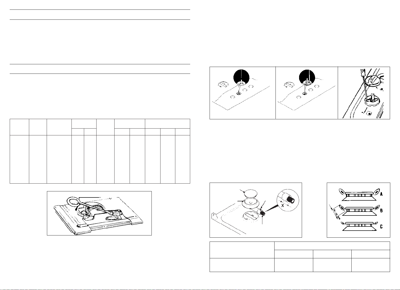
Adapting the hob to different types of gas
To adapt the Hob for use with different types of gas, carry out the following instructions:
— remove the grids and burners
— insert the hexagonal spanner (supplied) into the burner support (Fig. 5)
— unscrew the injector and replace it with one suitable for the gas to be used (see
Table below)
— regulate minimum flame and flame combustion (see nexts chapters).
Gas connection(see page 11)
Hexagonal spanner
Fig. 5
Table of Gas Consumption 1 W = 0,860 kcal/h
GAS
TYPE
METHANE
MGAS
G 20
BUTANE
GAS
G 30
PROPANE
GAS
G 31
Ø INJECTORS
1/100 mm.
093
127
61
84
61
84
NOMINAL THERMAL
POWER
kW kcal/h
1,55 1.290
2,95 2.537
1,55 1.290
2,95 2.537
1,55 1.290
2,95 2.537
kW kcal/h
0,38 327
0,65 559
0,38 327
0,65 559
0,38 327
0,65 559
Norm. Min. Max.
20 17 25
28/30 20 35
37 25 45
CAPACITY
143 l/h
281 l/h
109 g/h
215 g/h
107 g/h
211 g/h
REDUCED THERMAL
POWER
PRESSURE
m bar
BURNER
MEDIUM
LARGE
MEDIUM
LARGE
MEDIUM
LARGE
Regulating the minimum flame
After lighting the burners, turn the control knob to the minimum setting and then remove the knob (this can easily be removed by apply a gentle pressure).
Using a small «Terminal» type screwdriver the regulating screw can be adjusted as in
Fig. 8. Turning the screw clockwise reduces the gas flow, whilst turning it anticlockwise
increases the flow – Use this adjustment to obtain a flame of approximately 3 to 4 mm
in length and then replace the control knob.
If GPL (cylinder) gas is being used, turn the screw clockwise right to the end of the
travel of the by-pass.
Screws regulating
(for differend models)
6
REGULATING THE BURNERS
Flame Combustion
For maximum efficiency from the burners, the correct combustion of the flame is necessary.
A good flame must be well aligned and without yellow tips (Fig. 7/B). If there is insufficient
air the flame will be uneven with yellow tips (Fig. 7/A). If there is too much air, the flame
will be very short and bright (Fig. 7/C). In these cases the combustion must be adjusted by
re-fitting the carburation tube to the Venturi (where there is insufficient air) or removing the
carburation tube (in the case of too much air). To position the carburation tube, the fixing
screws must be loosened, and retightened when the satisfactory combustion is obtained.
Standard regulation values are stated in fig. 6 and following table.
Fig. 6 Fig. 7
Type of
burner
Medium
Large
Quota «X» depending on type of gas
Butane G 30 Propane G 31 Methane G 20
5 mm 7 mm 2 mm
0 mm 5 mm 3 mm
BURNER CAP
BURNER
AIR REGULATION
SCREW
FIXING
SCREW
Fig. 8
Page 5
8
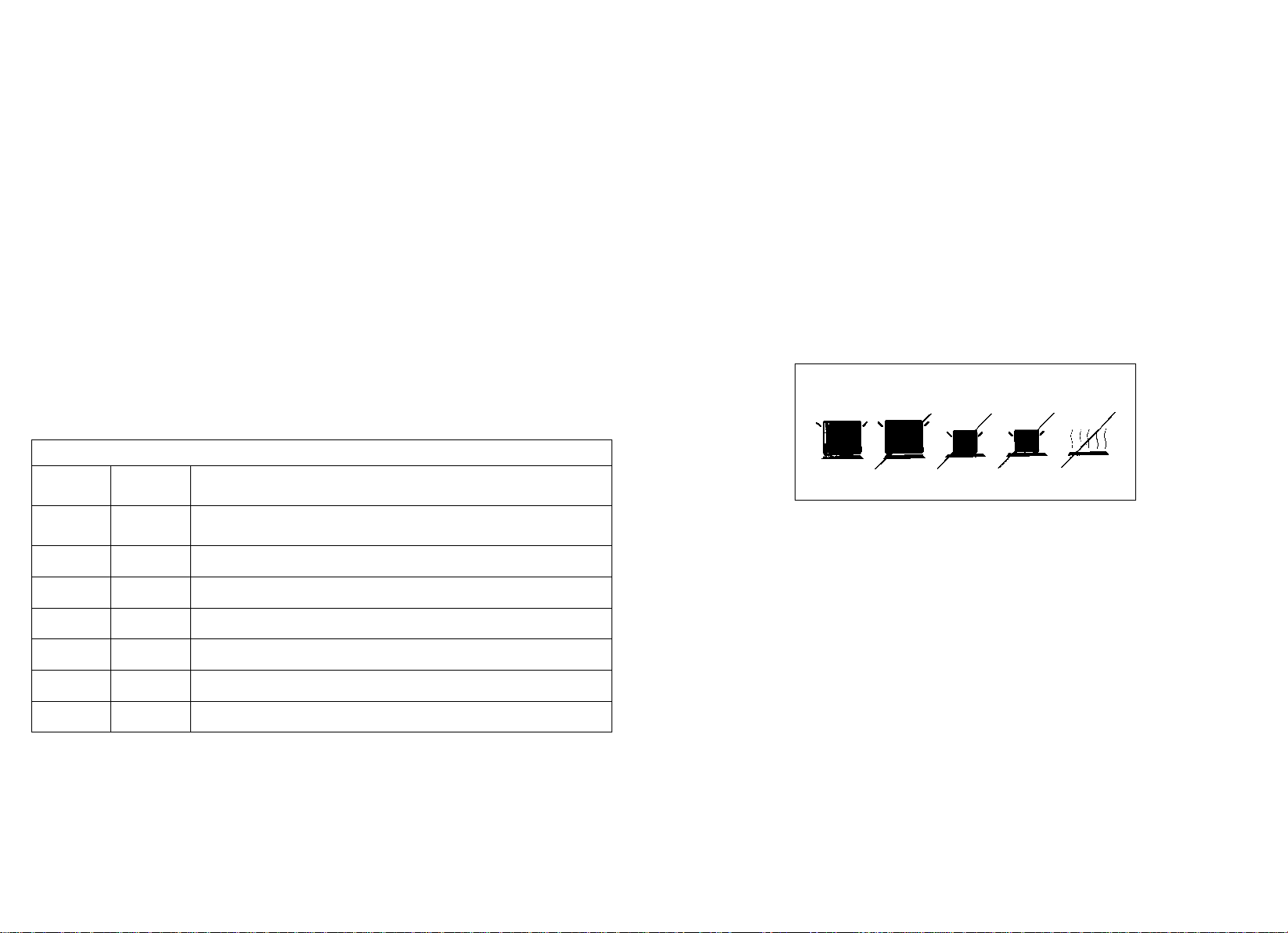
Fig. 9
YES NO NO NO NO
GENERAL ADVICE
For the best results, the flat-bottomed pans should match the gas burner size as follows:
— Medium from 12 - 20 cm.
— Large from 20 - 26 cm.
For smaller containers a reducer stand (supplied with some models) should be used
and the gas burner should be regulated so that the flame does not overlap the base
of the pan. The reducer stand is for use with the medium burner. Vessels with concave
or convex base should not be used.
WARNING:If a burner is accidentally extinguehed, turn the knob to the off position and do not attempt to re-ignite if for at least 1 minute.
To protect the glass lid from damage and in the interests of safety, the burners/plates
must be turned off and the burner/pan support/plate area must be cool before closing
the lid down.
Only pans which have smooth flat bases should be used on the electric hotplates. The
size of the pan should be as close as possible to the diameter of the hotplate, and never smaller (see Fig. 9). The base of the pan should be dry and spillages should be
avoided. Empty pans should not be left on the plates, nor should the plates left switched
on without a pan.
7
POWER OUTPUT - ELECTRIC HOTPLATES
Setting
0 OFF
1 VERY LOW Warming dishes & melting butter and chocolate
2 LOW Simmering, sauces, stews, milk puddings, poached eggs
3 MODERATE Vegetables, frozen foods, boiling water
4 MEDIUM Fresh Vegetables, pasta, fish, pancakes.
5 HIGH Omelettes, steaks
6 VERY HIGH Chops
INSTRUCTIONS FOR USE
Using the gas Burner
If the burners have not been used for a couple of days, wait for a few seconds before
lighting the burner, this will allow any air present in the pipes to escape.
To ignite the burners on hobs without electric ignition, place a lighted taper close to
the burner, press in and turn the control knob anti-clockwise.
For those hobs with electric ignition, simply turn the control knob to the ignition or maximum position and press the button marked ★. The spark is fired only when the button
is released. If the burner does not ignite first time, try again.
As a safety device, some models automatically cut off the gas supply if the flame is
accidently extinguished. In this case, push and rotate the control knob and keep it held
down for approx 5-6 seconds.
The burner will then remain lit.
ATTENTION: When cleaning the hob, take care to replace the burners correctly,
this will ensure that the ignition point is not blocked.
Use of electric hotplates
For the best use of the electric hotplates and to minimise energy consumption, the
following recommendations should be noted.
A neon indicator light adjacent to the control knob will glow when the electric plate is
in use.
Page 6

9
MAINTENANCE AND CLEANING
Important Advice
Before cleaning the Hob, ensure the appliance has cooled down. S
witch off the
electricity supply.
When cleaning the enamelled, varnished or chrome sections, use warm soapy water
or a non caustic detergent. For stainless steel use an appropriate cleaning solution.
Hotplates should only be cleaned with a cotton cloth coated with vaseline or seed oil.
Never use abrasives, corrosive detergents, bleaching agents or acids. Avoid any acid
or alkaline substances (lemon, juice, vinegar etc.) on the enamelled, varnisched or stainless steel sections.
The burners can be cleaned with soapy water. To restore their original shine, use a
household stainless steel cleaner. After cleaning, dry the burners and replace.
It is important the Burners are replaced correctly.
This appliance must only be used for the purpose for which it is intended, domestic
cooking, and any other use will be considered improper and could therefore be danger
ous. The Manufacturer will not be responSIble for any damage or loss resulting from
improper use.
Lubricating the gas taps
If a gas tap becomes stiff, it should be dismantled, cleaned carefully with petrol and
smeared with a drop of special heat resistant grease.
The following operations should be carried but:
— disconnect the electrical power supply, close the gas supply tap from the mains or
cylinder.
— Remove the hob top plate by removing the corner screws and those under the
burners.
— Remove the two screws holding down the head flange.
— Remove the head flange and the retaining spring on the knob shaft.
— Remove the gas regulation cone, clean it with petrol and smear it with some heat
resistant grease, taking care not to obstruct any holes through which gas must pass.
— Re-assemble all the parts, making sure that the spring and the rotating axis of the
cone fitted to the knob shaft are correctly seated.
Aftercare
Before calling out a Service Engineer please check the following:
— that the plug is correctly inserted and fused;
— that the gas supply is not faulty.
If the fault cannot be identified:
switch off the appliance — do not tamper with it — call the Aftercare Service Centre.
The Manufacturer will not be responsible for any inaccuracy resulting from printing or transcript errors contained in this brochure. We reserve the right to carry out modifications to products as required, including
the interests of consumption, without prejiudice to the characteristics relating to safety or function.
10
NOTES
Electrical diagrams
ELECTRONIC IGNITION BUTTON
(incorporated)
1
Page 7

INSTRUCTIONS FOR ASSEMBLY OF THE HOB
TO THE GAS SUPPLY PIPES
These instructions are for Fitters qualified for installation of equipment in line with the
relevant national standard. All work must be carried out with the electricity supply disconnected.
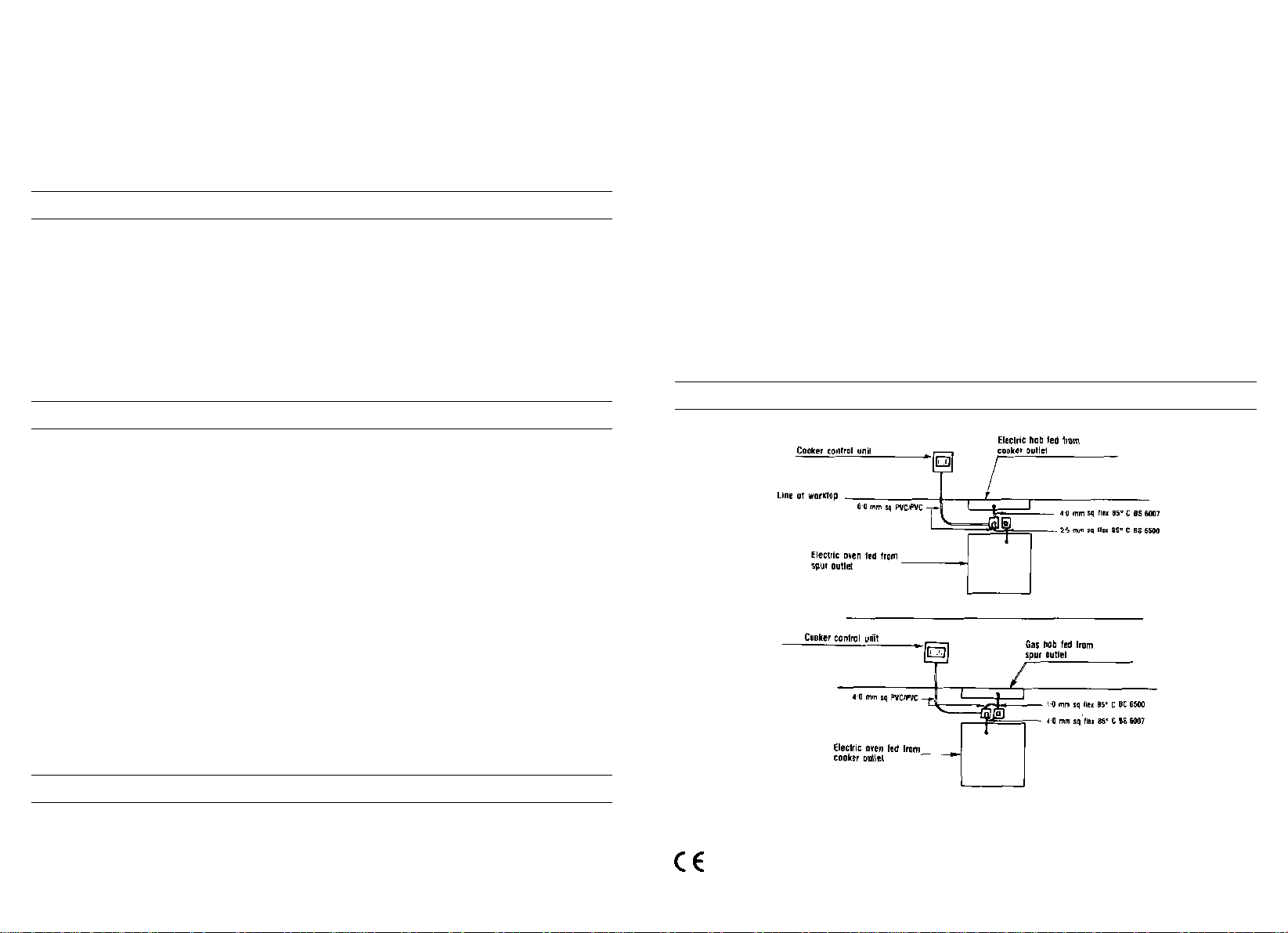
ASSEMBLY PROCEDURE
2 Spanners, sizes 17 and 23 mm are required.
1/2” GAS
A) As illustrated, assemble parts in sequence:
A) fixed pipe
B) washer
C) Elbow fitting with
tapered thred
connection
2) Tighten the joints
with the Spanners,
remembering to twist
the pipes into position
before tightening.
3) Attach fitting C to
mains supply using
rigid copper pipe.
VERY IMPORTANT
For ease of installation and to avoid gas leaks, it is recommended to connect the pipes as follows:
First connect the pipe to the Hob
and then
Connect the pipe to the gas supply.
In this sequence is not followed, there is a danger that gas will be trapped
in the pipe.
AFTER INSTALLATION, CHECK THE TIGHTNESS OF ALL JOINTS USING
A SOAPY SOLUTION
11
Page 8

13
Het vastzetten in het meubel geschiedt door de bijgeleverde bevestigingsbeugels die
aan de onderzijde op de daarvoor bestemde plaats worden vastgedraaid..
BELANGRIJK - BEVESTIGING AFDICHTINGSKIT
Belangrijk - op onderstaande tekening kunt u zien hoe de afdichtingskit moet worden aangebracht.
Dit apparaat is uitsluitend ontwikkeld voor huishoudelijk gebruik.
12
TECHNISCHE GEGEVENS
Kookplaten 60x50
Elektrisch
Kookzones 4 elektrisch
Type verwijzing PE 01
Spanning/frequentie (V/Hz) *
Vermogen elektrische installatie (W) 6300
Afmeting mm. 585x500
Beveiligingsgraad Type Y
Fig. 1
Fig. 4
Fig. 4 bis
Fig. 2
150 mm
minstens
30 mm
10 mm
INSTALLATIE
De installatie is de verantwoording van de koper. De frabrikant is vrijgesteld van deze
verantwoordelijkheid. Als de service dients wordt ingeschakeld voor een defect ontstaan
door foutieve installatie valt dit niet onder de garantie.
Deze inbouwkookplaten zijn bestemd voor installatie in een werkblad dat bestand is
tegen temperaturen van 100 °C en een dikte hebben tussen 25 en 40 mm. Voor de
inbouwmaat dient u zich te houden aan de maten zoals aangegeven in figuur 1.
De kookplaat dient zo te worden ingebouwd dat
er aan de linker- en rechterzijde minstens 150
mm. ruimte is tussen kookplaat en kasten of verticale panelen. De afstand tussen kookplatte en
achterwand dient minstens 55 mm. te zijn (fig. 2).
Indien de kookplaat wordt gebruikt zonder dat er
een apparaat onder wordt gemonteerd, dient
er tussen de kookplaat en het onderkasjie een
afscheiding door middel van een plaet te worden
gemontereerd (fig. 2). Deze plaat dient minstens
10 mm, afstand te hebben van de onderzijde van de kookplaat.
* 220-240V~/380-415 V3N~
Page 9

1514
Aansluiten (elektrische gedeelte)
Controleer de gegevens op het typeplaatje op het apparaat, die zich bevindt aan
de
binnenzijde onder in de kookplaat, en verzeker u er vervolgens van dat dit overeenkomt met de plaatselijk geldende normen nodig voor een goed functioneren.
Voordat u het apparaat aansluit controleer of het goed is geaard.
De aarding van het apparaat is wettelijk verplicht. De fabrikant is niet verantwoordelijk
voor eventuele materiële of persoonlijke schade als gevolg van foutieve installaltie.
Voor apparaten zonder stekker dient u een stekker op het aansluitsnoer te monteren
die het vermogen als aangegeven op het typje plaatje kan verwerken. De aarde kabel
is uitgevoerd in groengeel.
Als u het aansluitsnoer gaat vervangen dient de aarde kabel 10 mm. Ianger te zijn dan
de andere kabels. Gebruik uitsluitend een aansluitsnoer met rubber isolatie type H05RRF
.
De doorsnede van de draden dient minimaal 1,5 mm2te zijn voor verwarmingselementen en 0,75 mm2voor de overige apparaten. Daarnaast mag de diameter van de kabel aan de buitenzijde niet groter zijn dan 7 mm.
Conformiteitsverklaring. Dit apparaat, het gedeelte dat wordt aangesloten op het
lichtnet, is conform de richtlijnen van de CEE 89/109.
Het apparaat is conform de Europese richtlijnen 891336/CEE, 90/396/CEE,
73/23/CEE en daaropvolgende modificaties.
Elektrische aansluiting (4 elektrische kookzones)
Bij de installatie van dit toestel moet een TWEEPOLIGE SCHAKELAAR worden voorzien in de elektrische aansluiting.
Het elektrische kookveld moet worden aangesloten op een voeding van 30 ampère
door een bevoegde elektricien.
Voor het vervangen van de voedingskabel moet u de drie met “A” aangeduide schroeven losdraaien om het deksel te verwijderen. Breng nu de aansluiting op het net tot
stand met een kabel met voldoende vermogen. Sluit de voedingskabel aan op het
klemmenblok en op de aardingsaansluiting (Fig. 4).
Maak de kabel vast me de twee schroeven die zijn aangeduid met “B” en plaats het
deksel terug (Fig. 4 bis.) Controleer voor u het toestel aansluit de goede werking van
de aardingsketen. De aarding van dit toestel is bij wet verplicht. De fabrikant wijst elke
verantwoordelijkheid van de hand wanneer deze veiligheidsmaatregel niet wordt gerepecteerd. Voor de aansluiting op de elektrische voeding moet een kabel van 4,00
mm2, 85°C worden gebruikt, die via de verbindingskast op de besturingseenheid van
het kooktoestel wordt aangesloten.
Om de kabel aan te sluiten moet u eerst het deksel verwijderen, de kabel door de kabeldoorvoer steken en vastmaken. Maak de aansluiting volgens het schema op het etiket naast het klemmenbord en sluit de aardingsdraad aan op de draadpen naast het
klemmenbord. Roep voor de installatie steeds de hulp in van een bevoegd elektricien.
Gebruik van elektrische kookzones
Om de elektrische kookzones aan te zetten, is het voldoende om de knop op de
gewenste kookstand te zetten. Voor optimale prestaties met een minimum aan energieverbruik kunt u de volgende tabel raadplegen.
Het is geschikt voor plaatsing in een omgeving waarin de temperaturen binnen acceptabele limieten blijft en derhalve onderhevig aan de geldende Europese wetgeving.
Het is hoe dan ook aan te raden, in het geval dat er huishoudelijke apparaten onder
de kookplaat worden ingebouwd, een isolerende folie aan te brengen voor een optimale bescherming voor de kookplaat.
Apparaten type Y kunnen worden ingebouwd naast een hoge kast of wand mits
de afstand minimaal 5 cm bedraagt. Dit geldt ook voor installatie in een verlaagde
kookunit. Bij apparaten type X mogen de wanden niet te dicht bij het apparaat
staan. Zie hiervoor de Technische gegevens, beveiligingsgraad.
GEBRUIK VAN DE ELEKTRISCHE KOOKZONES
Positie
0 UIT
1 ZEER LAAG Bordenwarmen, smelten van boter en chocolade...
2 LAAG Opwarmen van kleine hoeveelheden en malen van sauzen...
3 ZACHT Koken van zachte groente, fruit. Aan de kook houden van water...
4 GEMIDDELD Doorkoken van groente, pasta en bereiden van vis...
5 HOOG Vlees braden...
6 ZEER HOOG Aan de kook brengen. Braden en frituren...
Voor optimaal gebruik van de branders raden wij u aan pannen te gebruiken die bij de
branders passen.
Page 10

17
Technische dienst
Het kan natuurlijk gebeuren dat er met uw kookplaat iets niet in orde is. Alvorens de
service dients te bellen (in het geval dat de kookplaat niet goed werkt):
— controleer of de stekker juist is aangesloten en in het stopcontact zit;
— controleer of de gastoevoer goed is.
In het geval dat er iets niet functioneert, haal dan de stroom van het apparaat. Maak
het apparaat in geen geval open maar neem contact op met de Technische dienst.
Het apparaat is voorzien van een standaard garantie certificaat.
ONDERHOUD EN REINIGEN
Belangrijke waarschuwing
Voordat u gaat demonteren of schoonmaken dient u de stroomvoorziening af te sluiten
door de stekker uit het stopcontact te halen of de stroomtoevoer via de zekering af te
sluiten. Zorg ervoor dat het apparaat volledig is afgekoeld.
Reinig de geëmailleerde, verchroomde en geverfde delen met handwarm water en
met een niet agressieve allesreiniger .
Gebruik voor de roestvrijstalen delen een rvs reiniger die gewoon in de winkel verkrijgbaar is.
Aluminium kunt u het beste reinigen door eerst met een met olie doordrenkte doek te
poetsen en dit vervolgens met een alcoholhoudend middel af te nemen.
Gebruik tijdens het schoonmaken nooit: schuurmiddelen, bijtende schoonmaakmiddelen, bleekmiddel of zuren.
Voorkom dat er op de geëmaillerde, roestvrijstalen of geverfde delen zuren blijven liggen (azijn, citroensap etc.)
De brandervoet kunt u reinigen met water en allesreinger. Als u de oorspronkelijk glans
terug wilt krijgen, kunt u een speciaal schoonmaakmiddel voor aluminiumlegeringen
gebruiken.
De branderdeksel, gemaakt van staal met emaille, kunt u reinigen in warm water met
reinigingsmiddel. U dient alle aangekoekte deeltjes te verwijderen die onregelmatigheid
in de vlam kunnen veroorzaken.
Na het reinigen moeten brandervoet en branderdeksel goed worden gedroogd. Let hierbij
op de de buisjes in de brandervoet. Zet daarna de branders zorgvuldig op hun plaats.
LET OP: Zorg er voor dat na het schoonmaken de branders op de juiste plaats
zitten en dat de branderdeksel goed op de brandervoet zit. Dit om een slecht
vlambeeld en schade aan de brandervoet te voorkomen.
Dit apparaat is ontwikkeld en geproduceerd voor koken bij huishoudelijk gebruik. Elke
andere vorm van gebruik is onjuist en derhalve gevaarlijk.
De fabrikant kan niet aansprakelijk worden gesteld voor eventuele schade veroorzaakt
door onjuist, onredelijk en onverantwoord gebruik.
16
Bij het gebruik van de elektrische kookzones raden wij u aan pannen te gebruiken met
een vlakke bodem en een diameter die overeenkomt met die van de gekozen kookzone. Zeker geen kleinere diameter gebruiken (fig. 9). Wij raden u aan de bodem van
de pan goed te drogen bij eventueel overkoken. Laat nooit een kookzone aanstaan
zonder pan of met een lege pan.
Fig. 9
JA NEE NEE NEE NEE
De frabrikant is niet verantwoordelijk voor mogelijke fouten in de gebruiksaanwijzing veroorzaakt door drukof zetfouten. De fabrikant behoudt zich het recht voor de produkten tussentijds te wijzigen indien zij dit
nodig of nuttig acht.
Page 11

18 19
INSTALACIÓN
La instalación corre a cargo del comprador. El Fabricante queda exento de este servicio. Las posibles intervenciones requeridas al fabricante derivadas de una instalación
incorrecta no están incluidas en la garantía.
Las encimeras empotrables están preparadas para su instalación en cualquier material, siempre que éste resista a una temperatura de 100° C, y su espesor varie entre
25 y 40 mm. Las dimensiones del hueco para empotrar el aparato deben respetar
las indicadas en la fig. 1
En el caso que la encimera se encastre de modo que sobre su lado izquierdo o derecho quede
la pared de un mueble, la distancia entre la pared vertical y el borde de la encimera debe ser de
al menos 150 mm (fig. 2), mientras la distancia entre la pared posterior y el borde de la encimera debe ser de al menos 55 mm.
Cuando debajo de la encimera no se introduzca
ningún electrodoméstico, entre la encimera y el
hueco inferior debe ser insertada una pared de
división de material aislante (madera o similares).
Dicho panel debe encontrarse a una distancia mínima de 10 mm. del fondo de la enci-
mera
(fig. 2). La fijación al mueble se obtiene mediante abrazaderas de fijación suministradas como accesorios. En la parte inferior de la encimera están predispuestos los
agujeros en los que deben ser enroscadas las abrazaderas de fijación.
MUY IMPORTANTE - APLICACIÓN SELLANTE
Importante - La figura de abajo indica cómo aplicar el sellante.
Este aparato ha sido concebido para un uso de tipo no profesional en el interior
de las viviendas.
Fig. 2
Pared de división
150 mm
mín.
30 mm
10 mm
CARACTERISTICAS TECNICAS
Fuegos 60x50
eléctrical
Fuegos 4 eléct.
Referencia de tipo PE 01
Tensión/Frecuencia (V/Hz) *
Potencia eléctrica instalada (W) 6300
Dimensión producto (a x p) mm. 585x500
Grado de protección Type Y
Fig. 1
Fig. 4
Fig. 4 bis
* 220-240V~/380-415 V3N~
Page 12

21
Para sustituir el cable de suministro de potencia, destornillar los 3 tornillos señalados,
(A) para secar la tapa. A esta altura, debe ser conectado al principal proveedor con un
cable apropriado. Conectar el cable a la terminal y a la terminal de tierra (Fig. 4).
Apretar el cable con los 2 tornillos señalados (B) y poner la tapa de nuevo (Fig. 4 bis).
Antes de conectar el producto, comprobar la eficacia del circuito de tierra requerida
por la ley. El fabricante declina cualquier responsabilidad si esta medida no se toma.
La conexión a la toma eléctrica debería ser hecha por u cable 4 mm
2
85° C y conectada através de la unidad de empalme de la cocina hasta la unidad de control.
Para conectar el cable, extraer la tapa de protección, introducir el cable através de la
cuña del cable y apretarla. Realizar la conexión de acuerdo con le diagrama, vigilando
para conectar el cable de tierra cerca de la tabla de la terminal.
Buscar siempre el consejo de un electricista calificado para dicha instalación.
Uso de las placas eléctricas
Para un mejor funcionamiento y el menor consumo de energia, regular la posición de
los mandos de las placas eléctricas respetando los consejos de la tabla siguiente.
20
Estudios preliminares adecuados y una buena proyectación permiten que las temperaturas se contengan dentro de límites aceptables y siempre inferiores a las establecidas
por las normas europeas vigentes.
Sin embargo es aconsejable, en el caso que debajo de la encimera se instale un electrodoméstico, interponer un papel aislante térmico que asegure una ulterior protección
a los eventuales órganos de mando del electrodómestico situados encima del mismo.
La encimera está aislada térmicamente (según norma EN) y puede ser instalada:
cerca de paredes que superen en altura el plano de trabajo si fuera de tipo Y,
o cerca de paredes que no superen en altura el plano de trabajo si fuera de tipo
X. Ver referencia al grado de protección en la tabla características técnicas.
Enlace (parte eléctrica)
Controlar los datos indicados sobre la tarjeta del aparato, ubicada en la parte inferior
externa del mismo, y asegúrese que la tensión nominal de red y potencia disponibles
sean las adecuadas para su funcionamiento.
Antes de efectuar la conexión, verificar la eficiencia de la instalación de toma de tierra.
La toma de tierra del aparto es obligatoria por Ley. La Casa Constructora declina toda
responsabilidad por eventuales daños a personas o a cosas derivadas de una falta de
observación de esta norma.
Para eventuales modelos desprovistos de enchufe, montar sobre el cable un enchufe
normalizado que esté en condiciones de soportar la carga indicada en la tarjeta. El
conductor de tierra del cable se distingue por los colores amarillo verde.
En caso que se desee realizar una conexión fija a la red, se deberá interponer, entre
el aparato y la red un dispositivo omnipolar de interrupción con distancia de los contactos de al menos 3 mm.
En caso de sustitución del cable de alimentación, el conductor de tierra (amarillo-verde),
debe obligatoriamente medir cerca de 10 mm. más respecto a los conductores de línea.
Utilizar exclusivamente un cable de goma tipo H05RR-F.
La sección de los cables pequeños debe ser de 1,5 mm
2
por producto con elementos
calentadores eléctricos, y 0,75 mm
2
para los otros productos. Además, el diámetro ex-
terno máximo del cable non debe ser mayor de 7 mm.
Declaración de conformidad. Este aparato, en las partes destinadas a estar en con-
tacto con sustancias alimentarias, cumple la prescripción de la dir. CEE 89/109.
Aparato conforme con las directivas europeas 89/336/CEE, 90/396/CEE, 73/23/CEE
y sucesivas modificaciones.
Conexión eléctrica (4 platos eléctricos)
En la instalación de este producto, un interruptor de 2 polos deve ser incorporado en la
conexión eléctrica.
La encimera eléctrica debería ser conectada a la toma de (30 amp) por un electricista
calificado.
El funcionamiento de la encimera se refleja en el piloto especifíco.
POTENCIA PLACAS EN LAS DISTINTAS POSICIONES DE LOS MANDOS
Posiciones
0 APAGADO
1 LENTISIMO Mantener en caliente un plato, mantequilla fundida, chocolate...
2 LENTO Cocción a fuego lento, bechamel, estufado, arroz con leche, huevos al plato...
3 MODERADO Legumbres secas, surgelados, frutas, agua hirviendo...
4 MEDIO Manzanas al vapor, verduras frescas, pasta, pescado...
5 FUERTE Cocciones más complicadas, tortillas, bistecs, tripa...
6 VIVO Bistecs, costillas, frituras...
Page 13

23
MANUTENCION Y LIMPIEZA
Advertencias importantes
Antes de efectuar qualquier operación de despiece, se debe desconectar el enchufe
de la toma de corriente o quitar la corriente por medio del interruptor general de la
instalación eléctrica.
Antes de efectuar la limpieza es necesario esperar a que el aparato se enfrie: desinserte
entonces la conexión eléctrica desenchufando o quitando la alimentación por medio del
interruptor general.
Lavar las partes esmaltadas, barnizadas o cromadas, con agua templada y jabón o detergente líquido no corrosivo.
Para las partes de acero usar alcohol o las específicas soluciones existentes en el mercado. Para paneles y perfiles de aluminio, usar algodón o un paño impregnado de aceite
de vaselina o de semillas.
Limpiar y pasar con el alcohol.
Durante las operaciones de limpieza no utilizar nunca: abrasivos, detergentes corrosivos, lejía o ácidos.
Evitar dejar sobre las partes esmaltadas, barnizadas o de acero inox sustancias ácidas
o alcalinas (zumo de limón, vinagre, etc).
Los quemadores se limpian con agua enjabonada: si se desea obtener su brillo original, es suficiente limpiarlos con productos especificos para aleaciones de aluminio.
Tras cada limpieza secar perfectamente los quemadores y volver a colocarlos en
sus de origen.
Es indispensable controlar que el montaje se realice de forma perfecta, ya que
un incorrecto posicionamiento de los componentes puede ser causa de graves
anomalías en la combustión.
Este aparato deberá ser destinado sólo al uso para el cual ha sido concebido, es decir
la cocción de uso doméstico. Cualquier otro uso se debe considerar impropio y portanto peligroso.
El fabricante no puede ser considerado responsable de eventuales daños derivados
de usos impropios, erroneos e irracionales.
22
Fig. 9
SÍ NO NO NO NO
En el uso de placas eléctricas se recomienda utilizar sólo recipientes con fondo perfectamente plano y con el diámetro más cercano al de la placa escogida y nunca inferior
a él (fig. 9). Se aconseja secar bien el fondo de los recipientes, evitar desbordamientos
debido a la ebullición y no dejar nunca las placas encendidas sin olla o con olla vacía.
Asistencia Técnica
Antes de llamar al servicio de Asistencia Técnica
En caso de fallido funcionamiento de la encimera le aconsejamos que:
— verifique que el enchufe esté bien introducido en la toma de corriente;
— verifique que el flujo de gas sea regular.
En caso de no individuar la causa del mal funcionamiento:
apague el aparato, no lo manipule y llame al Servicio de Asistencia Técnica.
El aparato está dotado de un certificado de garantía que le permite disfrutar del Servicio de Asistencia Técnica.
El fabricante no responde de posibles inexacitudes imputables a errores de imprenta o transcripción, contenidas en el presente opúscolo. Se reserva de aportar a los propios productos las modificaciones que
considere necesarias o útiles, también en el interés del usuario, sin perjudicar las características de funcionalidad y seguridad.
Page 14

Grafica R.B. - 05/2003 - Cod. 9150332.6
 Loading...