

Page 1

INSTRUCTIONS FOR INSTALLATION AND USE
MONTAGE- UND GEBRAUCHSANWEISUNG
INSTRUCTIONS POUR L'INSTALLATION ET L’UTILISATION
ISTRUZIONI PER L'INSTALLAZIONE E L’USO
INSTRUCCIONES PARA INSTALACIÓN Y USO
INSTRUÇÕES DE INSTALAÇÃO Y UTILIZAÇÃO
AANWIJZING VOOR GEBRUIK EN INSTALLATIE
Page 2

ENGLISH
DESCRIPTION
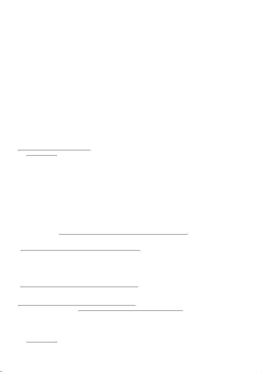
The hood may be installed in the filtering version, in the ducting version or in the version with an external motor.
Filtering version (Fig. 1): The hood aspirates the kitchen air saturated with fumes and odours, purifies it through the
grease filters and charcoal filters and returns clean air into the room. WARNING: When using filtering hoods, both
charcoal filters and an air baffle must be used; located in the upper part of the pipe, this baffle recycles the air to the
environment (Fig. 1A). For constant efficiency, the charcoal filters must be replaced periodically. The charcoal filters
are not supplied.
Ducting version (Fig. 2): The hood aspirates the kitchen air saturated with fumes and odours, passes it through the
grease filters and expels it to the outside through an outlet pipe. With this version the charcoal filters are not required.
Version with an external motor (Fig. 3): the hood is connected to a vacuum motor set outside the kitchen, or outside
the building; the motor aspirates the kitchen air saturated with fumes and odours making it go through the anti-grease
filters of the hood, then through the air disposal duct to make it go outside.
If you chose to install this version of the hood, you have to buy it already fit for this installation, which means without
the motor inside; moreover you have to buy a vacuum motor (only use vacuum units suggested in the original
catalogue). With this version the charcoal filters are not required.
Decide from the outset on the type of installation (filtering, ducting or with an external motor). For greater
efficiency, we recommend you install the hood in the ducting version or in the version with an external motor (if
possible). Attention: you can chose to install the hood with an external motor only if you have bought a hood already
planed for this version.
INSTALLATION
ATTENTION: The appliance should be installed by a qualified operator.
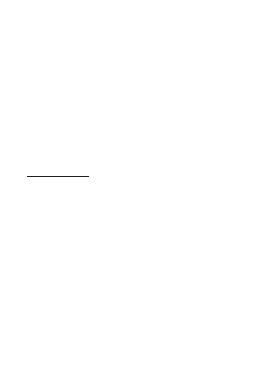
Remove the grease filter/s before proceeding with the assembly instructions. This will make the appliance easier
to handle. To remove the grease filters (Fig. 4): this is carried out by pushing the relative catch inwards and turning
it downwards until it disengages from the supports.
INSTALLATION IN DUCTING VERSION:
1. Before fixing, the disposal duct for air evacuation to the outside must be installed. Use an disposal duct with:
– minimum indispensable length; – minimum possible bends (maximum angle of bend: 90°); – certified material
(according to the State); – an as smooth as possible inside. It is also advisable to avoid any drastic changes in pipe
cross-section (recommended diameter: 150 mm). For air evacuation to the outside, follow all the other instructions
given on the “Warnings” sheet.
Prepare the power supply within the telescopic flue (for the electrical connection, follow all the other instructions on
the “Warnings” sheet).
2. Fixing to the wall (Fig. 5): Using the special drilling template, drill the required holes in the wall. As
previously specified in the chapter “Warning” remember there must be a minimum of 650 mm between the bottom
edge of the hood and the top of the stove. Before installing the hood, check that the brackets fixing screws (Fig. 5A)
have been sufficiently slackened to allow the hood itself to be fitted in place. Secure the metal brackets (A) to the
wall using the screws and plugs (brackets, screws and plugs are all supplied with the unit). Now fit on the hood using
the relative rectangular slots situated at the rear of the appliance. Adjust the horizontal position, shifting the hood to
the right or left as needed lining it up with the wall units. If the height of the hood also requires adjustment, use the
special regulation screws (B) (supplied). Once regulation has been completed, finish securing the hood with 2 more
screws (C): mark the points for the 2 holes on the wall, remove the hood and drill (8mm diameter holes); then use
the plugs and screws to complete installation.
3. Fixing with the rear panel (upon request) - Fig. 6: The rear metal panel must be fixed to the wall in the
upper part of the hob. Rest the lower edge of the panel behind the hob and fix the upper edge to the wall by means
of the two holes in the panel itself, inserting the supplied screws and screw anchors (A). The appliance should be
fixed to the rear panel in the same way as wall fixing, using the supplied hood brackets and the screws and screw
anchors supplied with the panel (B).
4. Fixing the telescopic flues: Using the supplied screws and screw anchors, fix the upper flue bearing
bracket to the ceiling and/or wall, checking that it is aligned with the hood (Fig. 7). Prepare the telescopic flues,
remembering that their final position must be that illustrated in Fig.8 (turn upside down the upper flue so that the air
disposal gratings are downwards). Connect the disposal duct to the air evacuation pipe of the hood. Use a flexible
pipe and lock it to the air evacuation pipe of the hood with a metal hose clamp - Fig. 9 (pipe and clamp are not
provided). Make the electrical connections. Fix the telescopic flue to the bracket by the screws provided (Fig. 10A).
Fix bottom side of the telescopic flue to the hood by the screws provided. Screws must be worked from the inside
of appliance (Fig. 11A).
Installation is now complete and the grease filters can be reassembled.
Page 3

INSTALLATION IN FILTERING VERSION:
Prepare the power supply within the telescopic flue (for the electrical connection, follow all the other instructions
on the “Warnings” sheet).
Fixing to the wall: for fixing to the wall refer to the instructions for the ducting version (see point 2, 3), then
continue with the instructions below.
Fixing the telescopic flues: Using the supplied screws and screw anchors, fix the upper flue bearing bracket
to the ceiling and/or wall, checking that it is aligned with the hood (Fig. 7). Prepare the telescopic flues, remembering
that their final position must be that illustrated in Fig.12 (the air disposal gratings must be positioned in the upper part).
Take the air baffle and fit a flexible pipe to it (150 mm diameter) locking it with a metal hose clamp (pipe and clamps
are not provided). Fit the air baffle to the upper flue (Fig. 13) with 4 screws. Fix the telescopic flue to the bracket by
the screws provided (Fig.10A). Lift the lower flue upward and lock it temporarily with some adhesive tape: that way
you can access the flexible pipe which must be connected to the flange on the air evacuation pipe (Fig. 14). Make
the electrical connection. Remove the adhesive tape and bring down the lower flue gently and fix it by means of 4
screws working from the inside of the hood (Fig. 11).
Remember that
are already fitted; if necessary, proceed to fit as follows, depending on the model type purchased:
- if the hood features a panel type charcoal filter (Fig. 15/16): Assemble the charcoal filter inserting the longer side
of the filter into the groove that runs parallel with the grease filter seat. Holding the filter on its side, insert the lock
supplied in its seat at the back (Fig. 15C) in order to avoid that it might be sucked onto the motor and bend it (Fig.
15A) so that its front side drives in (Fig. 15B). Fix the charcoal filter by means of the supplied locks (Fig. 16A), putting
them between the listel and the filter at the back of the seat of the filter. Keeping it blocked, make the lock rotate into
the back part until it embeds, minding that the charcoal filter does not get into the inside of the hood.
- if the hood features rectangular charcoal filter (Fig. 17): Install the charcoal filter fitting the two filter clips in their
housings and turning the filter upward.
Installation is now complete and the grease filters can be reassembled.
INSTALLATION IN VERSION WITH AN EXTERNAL MOTOR:
Before fixing the hood the air evacuation pipe running from the hood to the intaking motor should be ready . Use
an air evacuation pipe with: – minimum indispensable length; – minimum possible bends (maximum angle of bend:
90°); – certified material (according to the State); – an as smooth as possible inside. It is also advisable to avoid any
drastic changes in pipe cross-section (recommended diameter: 150 mm). For air evacuation to the outside, follow all
the other instructions given on the “Warnings” sheet.
Prepare the power supply within the telescopic flue (for the electrical connection, follow all the other instructions
on the “Warnings” sheet).
For fixing to the wall refer to the instructions for the ducting version (see point 2, 3), then continue with the
instructions below.
Fixing the telescopic flues: Using the supplied screws and screw anchors, fix the upper flue bearing bracket
to the ceiling and/or wall, checking that it is aligned with the hood (Fig. 7). Prepare the telescopic flues, remembering
that their final position must be that illustrated in Fig.8 (turn upside down the upper flue so that the air disposal gratings
are downwards). Connect the disposal duct to the air evacuation pipe of the hood. Use a flexible pipe and lock it to
the air evacuation pipe of the hood with a metal hose clamp - Fig. 9 (pipe and clamp are not provided).
Connect the hood to the external motor using the special terminal block (Fig. 18): remove wire clamp A and lid B from
the wiring junction box; fix the connecting wire of the external motor to terminal C; then replace wire clamp A and
lid B on the wiring junction box; the other end of the wire is secured to the terminal block on the external motor. Make
the electrical connection by means of the power cable.
Fix the telescopic flue to the bracket by the screws provided (Fig. 10A). Fix bottom side of the telescopic flue to the
hood by the screws provided. Screws must be worked from the inside of appliance (Fig. 11A).
Installation is now complete and the grease filters can be reassembled.
charcoal filters must be used in the case of the filtering version; check to see whether such filters
OPERATION
Depending on the model, the appliance is equipped with the following commands:
Commands shown in Fig. 19: Button A = light button. Button B = first speed motor ON/OFF button. Button C
= second speed button. Button D = third speed button. E = motor on light.
Commands shown in Fig. 20: Button A: turns the lights on/off; every 30 hours of operation the corresponding pilot
lamp comes on to indicate that the grease filters must be cleaned; every 120 hours of operation the corresponding
pilot lamp flashes to indicate that the grease filters must be cleaned and the charcoal filters replaced. To restart the
hour counter (RESET), hold the button A pressed down for about 1” (while the pilot lamp is on). Button B: drives
the motor in first speed (the corresponding pilot lamp comes on); when holding it down for about 1”, the motor cuts
out; when pressing the button a second time (while the pilot lamp is on) , the TIMER is activated and thus the motor
stops after 5’ (the pilot lamp flashes). Button C: drives the motor in second speed (the corresponding pilot lamp
comes on); when pressing the button a second time (while the pilot lamp is on) , the TIMER is activated and thus
the motor stops after 5’ (the pilot lamp flashes). Button D: drives the motor in third speed (the corresponding pilot
lamp comes on); when pressing the button a second time (while the pilot lamp is on) , the TIMER is activated and
thus the motor stops after 5’ (the pilot lamp flashes). Button E: drives the motor in fourth speed (the corresponding
Page 4

pilot lamp comes on); when pressing the button a second time (while the pilot lamp is on) , the TIMER is activated
and thus the motor stops after 5’ (the pilot lamp flashes).
Pay special attention to the grease filters: If the model purchased has the commands shown in Figure 19: the
grease filter must be cleaned periodically: exactly how often depends on use (at least once every other month). To
remove the filter: push inward on the clamp at the handle and pull the filter downward. Wash out the filter using a
neutral soap. If the model purchased has the commands shown in Figure 20: the grease filters must be cleaned
approximately once every 30 hours of operation (when the light button lamp comes on) - Fig. 20A. To remove the
filters: press inward on the clamps at the handles and pull the filter downward. Wash out the filter using a neutral soap.
Once the cleaned filters are reinstalled, to reset the counter hold the light button pressed down for about 1” (Fig.20A)
while the corresponding pilot lamp is on. For further information, see the Commands in Fig. 20 in the paragraph
entitled “Operation”.
Replacing the charcoal filters: If the unit is a filtering hood, the charcoal filters must be replaced: If the model
purchased has the commands shown in Figure 19, the charcoal filters must be replaced according to use: on average
once every 6 months. If the model purchased has the commands shown in Figure 20, the charcoal filters must be
replaced each time the light button (Fig. 20A) lamp flashes (i.e. every 120 hours of operation). To remove the charcoal
filter refer to the assembling instructions indicated in the paragraph concerning the assembling of the filtering version
hood, but doing the opposite.
Lighting: If the halogen light bulbs need changing, slacken the ring nut in an anticlockwise direction and remove
the bulb itself (Fig. 21). Replace with a bulb of the same type.
DEUTSCH
BESCHREIBUNG
Die Dunstabzugshaube kann in Umluftversion, in Abluftversion oder mit externem Motor installiert werden.
Umluftversion (Abb. 1): die Haube saugt die mit Rauch und Gerüchen gesättigte Luft an und reinigt sie durch die
Fett- und den Kohlefilter. Danach wird die saubere Luft wieder in den Raum geleitet. ACHTUNG: Wenn die
Dunstabzugshaube in der Umluftversion verwendet wird, müssen die Kohlefilter und eine Umluftweiche eingesetzt
werden; letztere wird am oberen Teil des Rohres fixiert und ermöglicht so, die wiederaufbereitete Abluft in den Raum
zurückzuleiten (Abb. 1A). Um die gleichmäßige Wirksamkeit der Kohlefilter zu erhalten, müssen sie regelmäßig
ausgetauscht werden. Die Kohlefilter werden nicht mitgeliefert.
Abluftversion (Abb. 2): die Haube saugt die mit Rauch und Gerüchen gesättigte Luft an, leitet sie durch die Fettfilter
und gibt sie über ein Abführungsrohr nach außen ab. Diese Version benötigt keinen Kohlefilter.
Version mit externem Motor (Abb. 3): die Dunstabzugshaube muss an eine Ansaugzentrale angeschlossen werden,
die sich ausserhalb der Küche oder des Gebäudes befindet; diese Ansaugzentrale saugt den Rauch und den Dunst
aus der Küche durch die Fettfilter der Dunstabzugshaube und durch das Abluftrohr an; zum Schluss leitet sie diese
ins Freie.
Falls die Dunstabzugshaube in Abluftversion installiert werden soll, muss die dementsprechende Version gekauft
werden, d.h. der Motorblock darf sich nicht im Inneren befinden; ausserdem muss eine Ansaugzentrale gekauft
werden (Bitte verwenden Sie nur eine der im Originalkatalog vorgeschlagenen Zentralen). Bei dieser Version
ist die Verwendung eines Aktivkohlefilters nicht notwendig.
Entscheiden Sie sich von Anfang an für einen Installationstyp (Umluft-, Ablufthaube oder mit externem Motor).
Um eine höhere Effizienz zu gewährleisten wird empfohlen, die Dunstabzugshaube in Abluftversion oder mit externem
Motor (wenn möglich) zu installieren. Achtung: die Dunstabzugshaube kann nur dann mit einem externen Motor
installiert werden, wenn sie in der dafür vorgesehenen Version gekauft wurde.
INSTALLATION
ACHTUNG: Es wird empfohlen, die Montage von Fachkräften durchführen zu lassen.
Vor Installation sind zur leichteren Handhabung des Geräts die Fettfilter/s zu entfernen. Zum Entfernen der
Fettfilter (Abb.4) sind die entsprechenden Filterhalter zu betätigen: die Fettfilter sind nach innen zu drücken und
anschließend nach unten zu drehen, um sie aus ihren Auflagen herauszunehmen.
INSTALLATION DER ABLUFTVERSION:
1. Vor der Befestigung muss das Rohr zur Abführung der Luft nach außen angebracht werden. Ein Abführungsrohr
verwenden, das folgende Eigenschaften besitzt: - erforderliche Mindestlänge; - so wenig Kurven wie möglich (maximale
Kurvenkrümmung: 90°); - zulässiges Material (Landesnormen); - Innenseite so glatt wie möglich. Es wird außerdem
empfohlen, starke Wechsel des Rohrdurchmessers zu vermeiden (empfohlener Durchmesser: 150 mm). Für die
Luftabführung nach außen alle weiteren Angaben im Blatt “Hinweise” befolgen.
Die Stromzufuhr innerhalb des vom dekorativen Rohr benötigten Raums vorbereiten (für den elektrischen Anschluss
alle weiteren im Blatt “Hinweise” aufgeführten Angaben befolgen).
2. Befestigung an der Wand (Abb. 5): Bohren Sie mit der mitgelieferten Bohrschablone die Löcher an den
jeweiligen Stellen an der Wand. Wie bereits im Kapitel “Montage und Gebrauchsanweisung” beschrieben ist darauf
Page 5
zu achten, daß der Abstand zwischen dem unteren Rand der Haube und der Kochfläche mindestens 650 mm
beträgt. Bevor die Dunstabzugshaube aufgehängt wird ist zu überprüfen, ob die Schrauben zur Befestigung der Bügel
(A) so eingeschraubt sind, dass die Haube aufgehängt werden kann. Die Metallbügel (A) mit Hilfe von Schrauben und
Dübeln an der Wand befestigen (Bügel, Schrauben und Dübel sind mitgeliefert). Dann die Dunstabzugshaube an den
rechteckigen Ösen, die sich auf der Rückseite des Gerätes befinden, aufhängen.
Die horizontale Position regulieren, indem die Haube in Übereinstimmung mit der Anordnung der Hängeschränke
nach rechts oder nach links verschoben wird. Soll die Haube auch in der Höhe reguliert werden, so nimmt man auf
die Regulierschrauben (B) (m Lieferumfang inbegriffen) Einfluß. Nach erfolgter Regulierung wird die Haube definitiv
mit 2 Schrauben (C) befestigt: Markieren Sie die 2 zu bohrenden Löcher auf der Wand, entfernen Sie die Haube und
bohren Sie (Durchmesser 8mm); benutzen Sie dann zur definitiven Befestigung die mitgelieferten Dübel.
3. Montage des Geräts auf Stahlrückwand (auf Anfrage) - Abb. 6: Zunächst wird die Stahlrückwand über der
Arbeitsplatte montiert. Hierzu wird der untere hintere Rand der Rückwand hinter die Arbeitsplatte eingeführt, bis die
Rückwand fest auf der Arbeitsplatte aufsitzt. Anschließend wird die Rückwand durch die beiden Bohrungen am
oberen Rand mit, für die Wand geeigneten, Dübeln und Schrauben an der Wand befestigt (A). Die weitere Befestigung
des Geräts auf der Stahlrückwand erfolgt analog zur Wandbefestigung (B).
4. Befestigung der Teleskoprohre: Zunächst wird die Position des Kaminbefestigungsteiles festgelegt. Dieses
kann sowohl an der Decke, als auch an der Wand festgeschraubt werden (Abb. 7). Nun werden die beiden Kaminteile
entsprechend der Geräteversion vorbereitet - Abb. 8 - (das obere Rohr umdrehen, so dass sich die Gitter zum
Ablassen der Luft unten befinden). Das Luftabführungsrohr an die Austrittsöffnung der Haube anschließen; dazu einen
Schlauch verwenden und ihn an der Luftaustrittsöffnung der Haube mit einer Metallschelle befestigen - Abb. 9 (Schlauch und Schelle werden nicht mitgeliefert). Elektrische Verbindung vollziehen. Das obere Teils des
Teleskopkamins wird nach oben gezogen und am oberen Kaminbefestigungsteil festgeeschraubt (Abb. 10A). Das
Unterteil des Teleskopkamins wird von unten mit dem Gerätegehäuse verschraubt (Abb. 11A).
Nun ist die Montage abgeschlossen und die Fettfilter können wieder eingesetzt werden.
INSTALLATION UMLUFTVERSION:
Die Stromzufuhr innerhalb des vom dekorativen Rohr benötigten Raums vorbereiten (für den elektrischen Anschluss
alle weiteren im Blatt “Hinweise” aufgeführten Angaben befolgen).
Befestigung an der Wand: für die Wandbefestigung die Anleitung für die Abluftversion hinzuziehen (siehe Punkt
2, 3), dann gemäß der unten aufgeführten Anweisungen fortfahren.
Befestigung der Teleskoprohre: Den oberen Stützbügel des Teleskoprohrs mit Hilfe der mitgelieferten Schrauben
und Dübel an der Wand und/oder an der Zimmerdecke befestigen, dabei muss er in der Mitte der Dunstabzugshaube
sein (Abb. 7). Die Teleskoprohre vorbereiten, dabei ist zu beachten, dass deren endgültige Position die in Abb. 12
dargestellte sein muss (die Gitter zum Ableiten der Abluft müssen sich oben befinden). Mit Hilfe einer Metallklemme
einen Schlauch (von 150 mm Durchmesser) an der Umluftweiche befestigen (Schlauch und Klemmen sind nicht
mitgeliefert); die Umluftweiche mit vier Schrauben am oberen Rohr befestigen (Abb. 13). Das obere Teils des
Teleskopkamins wird nach oben gezogen und am oberen Kaminbefestigungsteil festgeeschraubt (Abb. 10A). Das
untere Rohr nach oben schieben und provisorisch mit Klebeband fixieren: so ist der Zugriff möglich auf den Schlauch,
der an die Luftaustrittsöffnung angeschlossen werden muss (Abb. 14). – Den elektrischen Anschluss durchführen. –
Das Klebeband entfernen und das untere Rohr wieder nach unten schieben. Dieses dann, vom Inneren der
Dunstabzugshaube her, mit 4 Schrauben fixieren (Abb. 11).
• Beachten Sie, dass
bereits installiert sind; falls erforderlich, montieren Sie diese wie nachstehend beschrieben ist, entsprechend dem von
Ihnen erworbenen Modell:
- wenn die Haube mit einem Kohlefilterpaneel ausgestattet ist (Abb. 15/16): Nun zum Montieren der Faserplatte die
Längsseite des Filters in den Parallelkanal des Sitzes des Fettfilters einführen. Den Filter seitlich halten und den
Ausstattungs-Feststeller hinten in seinen Sitz einfügen (Abb. 15C), um dessen Ansaugen vom Motor her zu verhüten,
und sorgfältig auf solche Weise biegen (Abb. 15A), dass er in die Vorderseite einschnappt (Abb. 15B). Die Faserplatte
mit den Ausstattungs-Feststellern (Abb. 16A) befestigen, indem man diese zwischen Leiste und Filter hinten am
Filtersitze einklemmt. Den Feststeller hinten festhalten und drehen, bis er einklemmt und darauf achten, dass die
Faserplatte nicht in den Innenraum der Haube gelangt.
- wenn die Haube mit Rechteckigen Kohlefilter ausgestattet ist (Abb. 17): Den Kohlefilter installieren, dazu die beiden
Laschen des Filters in den vorgesehenen Sitz einfügen und ihn nach oben drehen.
Nun ist die Montage abgeschlossen und die Fettfilter können wieder eingesetzt werden.
INSTALLATION DER VERSION MIT EXTERNEM MOTOR:
Vor der Befestigung muss das Abluftrohr so positioniert werden, dass die Abluft von der Dunstabzugshaube zur
Ansaugzentrale geleitet werden kann. Ein Abführungsrohr verwenden, das folgende Eigenschaften besitzt: - erforderliche
Mindestlänge; - so wenig Kurven wie möglich (maximale Kurvenkrümmung: 90°); - zulässiges Material (Landesnormen);
- Innenseite so glatt wie möglich. Es wird außerdem empfohlen, starke Wechsel des Rohrdurchmessers zu vermeiden
(empfohlener Durchmesser: 150 mm). Für die Luftabführung nach außen alle weiteren Angaben im Blatt “Hinweise”
befolgen.
Die Stromzufuhr innerhalb des vom dekorativen Rohr benötigten Raums vorbereiten (für den elektrischen Anschluss
alle weiteren im Blatt “Hinweise” aufgeführten Angaben befolgen).
Für die Wandbefestigung die Anleitung für die Abluftversion hinzuziehen (siehe Punkt 2, 3), dann gemäß der
bei der Umluftversion der Gebrauch von Kohlefiltern erforderlich ist; uberprüfen Sie, ob die Filter
Page 6

unten aufgeführten Anweisungen fortfahren.
Befestigung der Teleskoprohre: Zunächst wird die Position des Kaminbefestigungsteiles festgelegt. Dieses
kann sowohl an der Decke, als auch an der Wand festgeschraubt werden (Abb. 7). Nun werden die beiden Kaminteile
entsprechend der Geräteversion vorbereitet - Abb. 8 – (das obere Rohr umdrehen, so dass sich die Gitter zum
Ablassen der Luft unten befinden). Das Luftabführungsrohr an die Austrittsöffnung der Haube anschließen; dazu einen
Schlauch verwenden und ihn an der Luftaustrittsöffnung der Haube mit einer Metallschelle befestigen - Abb. 9 (Schlauch und Schelle werden nicht mitgeliefert).
Wird die Haube über die entsprechenden Klemmleisten elektrisch mit der externen Zentrale verbunden (Abb. 18):
Entfernen Sie den Kabelfeststeller A und den Deckel B vom Anschlußkasten; Befestigen Sie das Verbindungskabel
der Zentrale an der Klemmleiste C; Den Kabelfeststeller A und den Deckel B des Schaltkastens wieder montieren.
Das andere Kabelende ist an der Klemmleiste der externen Zentrale zu befestigen. Den elektrischen Anschluss
anhand des Versorgungskabels durchführen.
Das obere Teils des Teleskopkamins wird nach oben gezogen und am oberen Kaminbefestigungsteil festgeeschraubt
(Abb. 10A). Das Unterteil des Teleskopkamins wird von unten mit dem Gerätegehäuse verschraubt (Abb. 11A).
Nun ist die Montage abgeschlossen und die Fettfilter können wieder eingesetzt werden.
FUNKTIONSWEISE
Je nach Version ist das Gerät mit folgenden Bedienung ausgestattet:
Bedienung gemäß Abb. 19: Schalter A: Beleuchtung. Schalter B: Ein- (erste Betriebstufe), Aus- Schalter.
Schalter C: zweite Betriebstufe. Schalter D: dritte Betriebstufe. Schalter E: Motorkontrolleuchte.
Bedienung gemäß Abb. 20: Taste A: Licht einschalten/ausschalten; alle 30 Betriebsstunden leuchtet die zutreffende
Anzeige auf und dies bedeutet, dass die Fettfilter zu reinigen sind; alle 120 Betriebsstunden blinkt die zutreffende
Anzeige auf und dies bedeutet, dass die Fettfilter gereinigt und die Kohlefilter ersetzt werden müssen. Zur
Wiederaufnahme der Stundenzählung (RESET) muss die Taste A circa 1” lang gedrückt werden (während die
Anzeige eingeschaltet ist). Taste B: Schaltet den Motor mit der Geschwindigkeit 1 ein (die zutreffende Anzeige
leuchtet auf); hält man die Taste circa 1” lang gedrückt, wird der Motor ausgeschaltet; wird die Taste ein zweites Mal
betätigt (während die Anzeige leuchtet), erfolgt die Aktivierung des TIMERS und nach 5’ kommt der Motor zum
Stillstand (die Anzeige blinkt). Taste C: Schaltet den Motor mit der Geschwindigkeit 2 ein (die zutreffende Anzeige
leuchtet auf); wird die Taste ein zweites Mal betätigt (während die Anzeige leuchtet), erfolgt die Aktivierung des
TIMERS und nach 5’ kommt der Motor zum Stillstand (die Anzeige blinkt). Taste D: Schaltet den Motor mit der
Geschwindigkeit 3 ein (die zutreffende Anzeige leuchtet auf); wird die Taste ein zweites Mal betätigt (während die
Anzeige leuchtet), erfolgt die Aktivierung des TIMERS und nach 5’ kommt der Motor zum Stillstand (die Anzeige
blinkt). Taste E: Schaltet den Motor mit der Geschwindigkeit 4 ein (die zutreffende Anzeige leuchtet auf); wird die
Taste ein zweites Mal betätigt (während die Anzeige leuchtet) erfolgt die Aktivierung des TIMERS und nach 5’ kommt
der Motor zum Stillstand (die Anzeige blinkt).
Mit besonderer Sorgfalt sind die Fettfilter zu behandeln: Hat das von Ihnen erworbene Modell die in Abb. 19
dargestellten Bedienung: Der Fettfilter ist periodisch in Abhängigkeit vom Gebrauch (mindestens jedoch alle zwei
Monate) zu reinigen. Entfernung des Filters: Den Festhalter in der Nähe des Griffs nach innen drücken und den Filter
nach unten ziehen. Den Filter mit einem neutralen Reiniger waschen. Hat das von Ihnen erworbene Modell die in Abb.
20 dargestellten Bedienung: die Fettfilter sind jeweils nach etwa 30 Betriebsstunden zu reinigen (wenn die Anzeige
der Lichttaste aufleuchtet - Abb. 20A). Entfernung der Filter: Den Festhalter in der Nähe des Griffs nach innen drücken
und den Filter nach unten ziehen. Die Filter mit einem neutralen Reiniger waschen. Sind die Filter wieder eingesetzt,
zur Wiederaufnahme der Stundenzählung circa 1” lang die Taste Licht (Abb. 20A) gedrückt halten, während die
Anzeige leuchtet. Weitere Informationen erhalten Sie unter dem Stichwort „Bedienung“ von Abb. 20 im Abschnitt
“Funktionsweise“.
Ersatz der Kohlefilter: Wird ein Gerät in Umluftversion eingesetzt, so müssen die Kohlefilter ersetzt werden.
Hat das von Ihnen erworbene Modell die in Abbildung 19 dargestellten Bedienung, müssen Sie die Kohlefilter in
Abhängigkeit vom Gebrauch im Durchschnitt alle 6 Monate ersetzen. Hat das von Ihnen erworbene Modell die in
Abb.20 dargestellten Bedienung, müssen Sie die Kohlefilter austauschen, wenn die Anzeige der Lichttaste (Abb. 20A)
blinkt, d. h. alle 120 Betriebsstunden). Um den Filter zu entfernen, entgegengesetzt dem Montieren der Faserplatte
vorgehen, wie es für die Hauben-Installierung in Umluft-Ausführung beschrieben ist.
Beleuchtung: Um die Halogenlampen zu ersetzen, die Nutmutter gegen den Uhrzeigersinn ausschrauben und die
Lampe entfernen (Abb. 21). Mit Lampen derselben Art ersetzen.
FRANCAIS
DESCRIPTION
Cette hotte peut être installée en version recyclage, en version aspirante ou en version avec moteur extérieur.
Version recyclage (Fig. 1) : votre hotte aspire l’air de la cuisine imprégné de fumée et d’odeurs, en l’épurant à travers
les filtres à graisse ainsi qu’à travers les filtres à charbon pour le renvoyer dans la pièce, propre. ATTENTION: Pour
la version Recyclage utiliser les filtres à charbons et un déflecteur placé dans la partie haute du conduit permettant
Page 7
la circulation de l’air dans la pièce (Fig. 1A). Afin que votre hotte soit efficace d’une façon constante, il est nécessaire
de remplacer les filtres à charbon périodiquement. Les filtres à charbon ne sont pas fournis.
Version aspirante (Fig. 2) : votre hotte aspire l’air de la cuisine imprégnée de fumée et d’odeurs, en le faisant passer
à travers les filtres à graisse, puis en l’éliminant à l’extérieur à travers un tuyau d’évacuation. Dans cette version
l’emploi du filtre à charbon n’est pas nécessaire.
Version avec moteur extérieur (Fig. 3): votre hotte doit être reliée à un moteur extérieur placé hors de la cuisine
ou à l’extérieur de l’édifice ; le moteur aspire l’air de la cuisine imprégné de fumée et d’odeurs, en le faisant passer
à travers les filtres à graisse de votre hotte, puis à travers le tuyau d’évacuation pour l’éliminer vers l’extérieur.
Si vous voulez installer votre hotte en optant pour cette version, vous devez acheter un modèle qui prévoit cette
installation, c’est-à-dire sans le groupe moteur à l’intérieur; vous devez de plus acheter un moteur aspirant (employez
uniquement les moteurs proposés dans le catalogue original). Cette version n’a pas besoin de filtres à charbon.
Vous devez décider dès le début quel type d’installation vous voulez (recyclage, aspirante ou avec moteur
extérieur). Afin d’avoir une hotte au rendement optimal, nous vous conseillons d’installer une hotte version aspirante
ou en version avec moteur extérieur (si cela est possible). Attention: vous ne pouvez choisir l’installation avec moteur
extérieur que si vous avez acheté une hotte déjà prévue pour cette version.
INSTALLATION
ATTENTION: Il est conseillé de confier les opérations d’installation à des spécialistes.
Avant de procéder aux opérations de montage, pour manoeuvrer plus aisément l’appareil, démontez le filtre/s
à graisse (Fig. 4): débloquez le dispositif d’arrêt et poussez les filtres vers l’intérieur en les tournant vers le bas
jusqu’à les dégager des supports.
INSTALLATION VERSION ASPIRANTE :
1. Avant de commencer l’installation, il est nécessaire de prévoir le tuyau pour l’évacuation de l’air vers
l’extérieur. Employez un tuyau d’évacuation qui ait : - la longueur minimale indispensable ; - le moins de coudes et
de raccords possibles (angle maximum des coudes : 90°) ; - qui soit fait d’une matière approuvée par les normes en
vigueur (suivant l’Etat) ; - sa surface intérieure la plus lisse possible. Nous vous conseillons aussi d’éviter les
changements brusques de section du tuyau (diamètre conseillé : 150 mm). Pour l’évacuation de l’air vers l’extérieur,
suivez toutes les autres indications données à la page “Attention”.
Prévoir l’alimentation électrique dans l’encombrement du tuyaux téléscopiques (pour le connexion électrique,
suivre toutes les autres indications se trouvant à la page “Attention”).
2. Fixation au mur (Fig. 5): En utilisant le gabarit de perçage spécial faites les trous dans le mur. Comme
indiqué au chapitre “Attention”, n’oubliez pas que la distance entre le bord inférieur de la hotte et le plan de cuisson
doit être au moins de 650 mm. Avant d’accrocher la hotte assurez-vous que les vis de fixation des étriers (A) sont
dévissés de manière à ce qu’il soit possible d’accrocher la hotte. Fixez les supports métalliques (A) au mur à l’aide
des vis et des chevilles (supports, vis et chevilles sont fournis). Ensuite fixez la hotte par les fentes rectangulaires
qui se trouvent à l’arrière de l’appareil. Réglez la position horizontale de l’appareil en déplaçant la hotte vers la droite
ou vers la gauche suivant les exigences d’alignement des meubles suspendus. Si vous devez régler la hotte en
hauteur, vous devez agir sur les vis (B) de réglage (fournies). Après avoir trouvé l’emplacement exact de votre
appareil, fixez-le définitivement à l’aide de 2 autres vis (C): tracez sur le mur l’emplacement des 2 trous à percer,
décrochez la hotte et percez les trous (diamètre 8 mm) ; ensuite utilisez les chevilles et les vis fournies pour la fixation
définitive.
3. Fixation avec panneau arrière (en option) - Fig. 6: Le panneau métallique sera placé contre le mur, dans
la partie supérieure de la table de cuisson. Appuyez le bord inférieur du panneau derrière la table de cuisson et
ancrez le bord supérieur au mur par les deux trous prévus dans le panneau, en y introduisant les vis et les chevilles
(A). La fixation de l’appareil au panneau arrière a lieu de la même façon que la fixation murale, en utilisant les étriers
de la hotte ainsi que les vis et les chevilles du panneau en dotation (B).
4. Fixation des tuyaux télescopiques: Au moyen des chevilles et des vis en dotation, fixez l’étrier supérieur
du tuyau télescopique au plafond et/ou au mur, de manière à ce qu’il soit aligné avec votre hotte (Fig. 7). Préparez
les tuyaux sans oublier que leur position finale devra être identique à celle de la Fig. 8 (retournez le tuyau supérieur
de façon à ce que les grilles d’évacuation de l’air soient dans la partie du bas). Raccordez le conduit pour l’évacuation
de l’air à la bouche de sortie de l’air de la hotte; utilisez un tuyau souple et bloquez-le sur la bouche de sortie de
l’air de la hotte à l’aide d’un collier métallique - Fig. 9 - (le tuyau et le collier ne sont pas fournis). Faire la connexion
électrique. Fixez les tuyaux télescopiques à l’étrier à l’aide des vis de fixation latérales (Fig. 10A). Fixez le tuyau
télescopique inférieur à la hotte en utilisant les vis prévues à cet effet, en l’enfilant par la partie intérieure de la hotte
(Fig. 11A).
L’installation est terminée, vous pouvez remonter les filtres à graisse.
INSTALLATION VERSION RECYCLAGE:
Prévoir l’alimentation électrique dans l’encombrement du tuyaux télescopiques (pour la connexion électrique,
suivre toutes les autres indications se trouvant à la page “Attention”).
Fixation au mur: pour la fixation au mur voir les instructions pour la version aspirante (voir points 2, 3), puis
continuer avec les instructions indiquées ci-après.
Fixation des tuyaux télescopiques: Au moyen des chevilles et des vis en dotation, fixez l’étrier supérieur du
Page 8

tuyau télescopique au plafond et/ou au mur, de manière à ce qu’il soit aligné avec votre hotte (Fig. 7). Préparez les
tuyaux sans oublier que leur position finale devra être identique à celle de la Fig. 12 (les grilles d’évacuation de l’air
doivent être positionnées dans la partie haute). Prenez le déflecteur de l’air et fixez-y un tuyau souple (de 150 mm
de diamètre) en le bloquant à l’aide d’un collier métallique (le tuyau et le collier ne sont pas fournis); fixez le déflecteur
de l’air au tuyau supérieur (Fig. 13) à l’aide de 4 vis. Fixez les tuyaux télescopiques à l’étrier à l’aide des vis de fixation
latérales (Fig. 10A). Soulevez le tuyau inférieur vers le haut et le bloquer temporairement avec une bande adhésive:
il sera ainsi possible d’accéder au tuyau souple qui doit être raccordé à la bouche de sortie de l’air (Fig. 14). Effectuez
la connexion électrique. Otez la bande adhésive et rabaissez le tuyau inférieur en le posant délicatement et fixezle au moyen de 4 vis en manoeuvrant de l’intérieur de votre hotte (Fig. 11).
Nous rappelons que
installés, dans le cas contraire, montez-les en procédant comme suit, en fonction du modèle en votre possession :
- si la hotte est équipée d’un filtre à charbon à panneau (Fig. 15/16): montez le filtre à charbon en insérant la partie
la plus longue du filtre dans le canal qui se trouve parallèlement à l’emplacement du filtre à graisse. En tenant le filtre
sur le côté, insérez l’arrêt qui vous est fourni à l’emplacement prévu par derrière (Fig. 15C) afin d’éviter qu’il soit
resucé sur le moteur et pliez-le (Fig. 15A) de sorte qu’il soit bloqué par l’avant (Fig. 15B). Fixez le filtre à charbon
au moyen des arrêts en dotation (Fig. 16A), en encastrant ceux-ci entre le listel et le filtre dans la partie postérieure
de l’emplacement du filtre. Faites tourner l’arrêt, en faisant en sorte qu’il soit toujours bloqué, dans la partie postérieure
jusqu’à ce qu’il s’encastre; faites attention à ce que le filtre à charbon ne rentre pas dans l’intérieur de la hotte.
- si la hotte est équipée d’un filtre à charbon rectangulair (Fig. 17): Installer le filtre à charbon en enfilant les 2
languettes du filtre dans le logement prévu à cet effet et en le faisant tourner vers le haut.
L’installation est terminée, vous pouvez remonter les filtres à graisse.
INSTALLATION VERSION AVEC MOTEUR EXTERIEUR:
Avant de fixer votre hotte il est nécessaire de prévoir le conduit pour l’évacuation de l’air allant de votre hotte
au moteur aspirant. Employez un tuyau d’évacuation qui ait : - la longueur minimale indispensable ; - le moins de
coudes et de raccords possibles (angle maximum des coudes : 90°) ; - qui soit fait d’une matière approuvée par les
normes en vigueur (suivant l’Etat) ; - sa surface intérieure la plus lisse possible. Nous vous conseillons aussi d’éviter
les changements brusques de section du tuyau (diamètre conseillé : 150 mm). Pour l’évacuation de l’air à l’extérieur,
suivez toutes les autres indications données à la page “Attention”.
Prévoyez l’alimentation électrique dans l’encombrement du tuyaux télescopiques (pour la connexion électrique,
suivez toutes les autres indications se trouvant à la page “Attention”).
Pour la fixation au mur voir les instructions pour la version aspirante (voir points 2, 3), puis continuer avec les
instructions indiquées ci-après.
Fixation des tuyaux télescopiques: Au moyen des chevilles et des vis en dotation, fixez l’étrier supérieur du
tuyau télescopique au plafond et/ou au mur, de manière à ce qu’il soit aligné avec votre hotte (Fig. 7). Préparez les
tuyaux sans oublier que leur position finale devra être identique à celle de la Fig. 8 (retournez le tuyau supérieur de
façon à ce que les grilles d’évacuation de l’air soient dans la partie du bas). Raccordez le conduit pour l’évacuation
de l’air à la bouche de sortie de l’air de la hotte; utilisez un tuyau souple et bloquez-le sur la bouche de sortie de
l’air de la hotte à l’aide d’un collier métallique - Fig. 9 - (le tuyau et le collier ne sont pas fournis).
Faites la connexion électrique entre le moteur extérieur et la hotte en utilisant les plaques de jonction appropriées
(Fig.18): enlevez l’élément A et le couvercle B de la boîte de connexion; fixez le câble de raccordement du moteur
à la plaque de jonction C; remontez l’élément A et le couvercle B de la boîte de connexion; l’autre extrémité du câble
doit être fixée à la plaque de jonction du moteur extérieur. Effectuez le raccordement électrique à l’aide du câble
d’alimentation.
Fixez les tuyaux télescopiques à l’étrier à l’aide des vis de fixage latérales (Fig. 10A). Fixez le tuyau inférieur à la
hotte en utilisant les vis prévues à cet effet, en l’enfilant par la partie intérieure de la hotte (Fig. 11A).
L’installation est terminée, vous pouvez remonter les filtres à graisse.
dans la version recyclage, l’utilisation des filtres à charbon est nécessaire ; vérifiez s’ils sont
FONCTIONNEMENT
Selon les modèles, l’appareil est muni des types suivants de commandes:
Commandes de la Fig. 19: Touche A: touche d’éclairage. Touche B: touche ON/OFF moteur 1e vitesse. Touche
C: touche 2e vitesse. Touche D: touche 3e vitesse. E: voyant lumineux de fonctionnement du moteur.
Commandes de la Fig. 20: Touche A: allume/éteint les voyants; toutes les 30 heures de fonctionnement le témoin
lumineux correspondant s’allume pour signaler qu’il est nécessaire de nettoyer les filtres à graisse; toutes les 120
heures de fonctionnement, le témoin lumineux correspondant clignote pour signaler qu’il est nécessaire de nettoyer
les filtres à graisse et remplacer les filtres à charbon. Pour faire repartir le comptage des heures (RAZ), maintenir
la pression sur la touche A pendant environ 1” (tandis que le témoin est en fonction). Touche B: actionne le moteur
à la 1ère vitesse (le témoin lumineux correspondant s’allume); pour éteindre le moteur, maintenir la pression pendant
environ 1”; en appuyant une seconde fois sur la touche (tandis que le témoin lumineux est allumé), le TIMER est
activé, par conséquent, 5’ après le moteur s’arrête (le témoin lumineux clignote). Touche C: actionne le moteur à
la 2ème vitesse (le témoin lumineux correspondant s’allume); en appuyant une seconde fois sur la touche (tandis que
le témoin lumineux est allumé), le TIMER est activé, par conséquent, 5’ après le moteur s’arrête (le témoin lumineux
clignote). Touche D : actionne le moteur à la 3ème vitesse (le témoin lumineux correspondant s’allume); une seconde
fois sur la touche (tandis que le témoin lumineux est allumé), le TIMER est activé, par conséquent, 5’ après le moteur
Page 9

s’arrête (le témoin lumineux clignote). Touche E : actionne le moteur à la 4ème vitesse (le témoin lumineux
correspondant s’allume); en appuyant une seconde fois (tandis que le témoin lumineux est allumé), le TIMER est
activé, par conséquent, 5’ après le moteur s’arrête (le témoin lumineux clignote).
Prêter une attention particulière aux filtres à graisse:
représentées sur la Figure 19: les filtres à graisse doivent être nettoyés périodiquement, en fonction de l’utilisation
(au moins tous les deux mois). Pour enlever le filtre: à l’aide de la poignée, pousser l’arrêt vers l’intérieur et tirer le
filtre vers le bas. Laver les filtres avec une lessive neutre. Si le modèle que vous avez acheté a les commandes
représentées sur la Figure 20: les filtres à graisse doivent être nettoyés environ toutes les 30 heures de fonctionnement
(lorsque le témoin de la touche éclairage s’allume - Fig. 20A). Pour enlever le filtre: à l’aide de la poignée, pousser
l’arrêt vers l’intérieur et tirer le filtre vers le bas. Laver les filtres avec une lessive neutre. Une fois les filtres propres
remontés, pour faire repartir le comptage, maintenir la pression pendant environ 1” sur la touche éclairage (Fig.20A)
tandis que le témoin lumineux correspondant est allumé. Pour toute information complémentaire voir les Commandes
de la Fig. 20 sous le paragraphe “Fonctionnement”.
Remplacer les filtres à charbons: si l’on utilise l’appareil en version recyclage, il faut remplacer les filtres à
charbons. Si le modèle que vous avez acheté a les commandes représentées sur la Figure 19, vous devrez remplacer
les filtres à charbons en fonction de l’utilisation, en moyenne tous les 6 mois. Si le modèle que vous avez acheté
a les commandes représentées sur la Figure 20, vous devrez remplacer le filtre à charbon toutes les fois que le
témoin de la touche éclairage (Fig. 20A) clignote (c’est-à-dire toutes les 120 heures de fonctionnement). Pour enlever
le filtre suivre les indications concernant l'assemblage du filtre à charbon illustré dans les indications concernant
l'installation de la hotte version recyclage, en faisant le contraire.
Eclairage: Pour le remplacement des lampes halogènes, dévissez la bague dans le sens contraire aux
aiguilles d’une montre et ôtez l’ampoule (Fig. 21). Montez une ampoule de même type.
Si le modèle que vous avez acheté aux commandes
ITALIANO
DESCRIZIONE
La cappa puo’ essere installata in versione filtrante, in versione aspirante o in versione con motore esterno.
Versione filtrante (Fig. 1): la cappa aspira l’aria della cucina impregnata di fumi e di odori, depurandola attraverso
i filtri anti-grasso ed i filtri carbone per poi re-immetterla pulita nella stanza. ATTENZIONE: Nell’uso in versione
filtrante è necessario utilizzare i filtri al carbone ed un deflettore aria che, posto nella parte superiore del tubo,
permetta il riciclo dell’aria nell’ambiente (Fig. 1A). Per una costante efficienza, è necessario sostituire periodicamente
i filtri al carbone. I filtri al carbone non sono in dotazione.
Versione aspirante (Fig. 2): la cappa aspira l’aria della cucina impregnata di fumi e di odori facendola passare
attraverso i filtri anti-grasso, poi la espelle all’esterno attraverso un condotto di scarico. In questa versione non è
necessario utilizzare il filtro al carbone.
Versione con motore esterno (Fig. 3): la cappa va collegata ad una centralina aspirante posta in al di fuori della
cucina o all’esterno dell’edificio; la centralina aspira l’aria della cucina impregnata di fumi e di odori facendola passare
attraverso i filtri anti-grasso della cappa, poi attraverso il condotto di scarico ed infine la espelle all’esterno.
Se volete installare la cappa in questa versione, dovete acquistarla già predisposta, cioè senza il gruppo motore
all’interno; inoltre dovete acquistare una centralina aspirante (usare solo centraline proposte nel catalogo origi-
nale). In questa versione non è necessario utilizzare il filtro al carbone.
Decidete sin dall’inizio il tipo di installazione (filtrante, aspirante o con motore esterno). Per una maggiore
efficienza, consigliamo di installare la cappa in versione aspirante o in versione con motore esterno (se possibile).
Attenzione: potete scegliere l’installazione con motore esterno solo se avete acquistato la cappa già predisposta per
questa versione.
INSTALLAZIONE
ATTENZIONE: si consiglia di affidare le operazione di installazione a personale specializzato.
Prima di procedere alle operazioni di montaggio, per una più facile manovrabilità dell'apparecchio disinserire il
filtro/i antigrasso. La rimozione dei filtri antigrasso (Fig. 4), avviene operando sull'apposito fermo, spingendoli verso
l'interno e ruotandoli verso il basso fino a disinserirli dai supporti.
INSTALLAZIONE IN VERSIONE ASPIRANTE:
1. Prima del fissaggio è necessario predisporre il condotto per lo scarico dell’aria all’esterno. Utilizzare un
condotto di scarico che abbia: – lunghezza minima indispensabile; – minor numero possibile di curve (angolo massimo della curva:90°); – materiale approvato normativamente (a seconda dello Stato); – lato interno piú liscio possibile. Si consiglia inoltre di evitare cambiamenti drastici di sezione del tubo (diametro consigliato: 150 mm). Per lo
scarico dell’aria all’esterno, seguire tutte le altre indicazioni riportate nel foglio “Avvertenze”.
Predisporre l’alimentazione elettrica entro l’ingombro dei tubi telescopici (per il collegamento elettrico, seguite
tutte le altre indicazioni riportate nel foglio “Avvertenze”).
2. Fissaggio a muro (Fig. 5): Usando l’apposita maschera di foratura praticare sulla parete i fori indicati nella
Page 10

stessa. Come già specificato nel capitolo "Avvertenze", tenere presente che la distanza tra il bordo inferiore della
cappa ed il piano cottura deve essere min 650 mm. Prima di agganciare la cappa assicurarsi che le viti di fissaggio
delle staffe (A) siano svitate in modo tale da consentire l’aggancio della cappa. Fissare le staffe metalliche (A) alla
parete tramite le viti e i tasselli (staffe, viti e tasselli sono in dotazione). Agganciate quindi la cappa tramite le asole
rettangolari apposite, situate nella parte posteriore dell’apparecchio. Regolare la posizione orizzontale spostando la
cappa a destra o a sinistra secondo le esigenze di allineamento ai pensili. Se avete l'esigenza di regolare la cappa
anche in altezza, operare sulle apposite viti (B) di regolazione (in dotazione). A regolazione avvenuta, fissare la cappa
definitivamente con altre 2 viti (C): segnare sul muro i 2 fori da fare, sganciare la cappa ed effettuare i fori segnati
(diametro 8mm); utilizzare poi i tasselli e le viti in dotazione per il fissaggio definitivo.
3. Fissaggio con pannello posteriore (a richiesta) - Fig. 6: Il pannello posteriore metallico sarà posizionato
a parete nella parte superiore del piano cottura. Appoggiate il bordo inferiore del pannello dietro al piano cottura ed
ancorate il bordo superiore alla parete tramite i due fori appositamente previsti sul pannello, inserendo le viti e i tasselli
in dotazione (A). Il fissaggio dell’apparecchio al pannello posteriore avviene in maniera analoga al fissaggio a muro,
utilizzando le staffe fornite a corredo della cappa (B) e le viti e i tasselli a corredo del pannello.
4. Fissaggio dei tubi telescopici: Mediante i tasselli e le viti in dotazione, fissare al soffitto e/o alla parete
la staffa superiore di supporto del tubo telescopico, facendo in modo che sia in asse con la vostra cappa (Fig. 7).
Preparate i tubi telescopici, tenendo presente che la loro posizione finale dovrà essere quella illustrata in Fig. 8
(capovolgere il tubo superiore in modo che le griglie di evacuazione aria siano in basso). Collegare il condotto per
lo scarico dell’aria con la bocca uscita aria della cappa; utilizzare un tubo flessibile e bloccarlo alla bocca uscita aria
della cappa con una fascetta metallica - Fig. 9 - (tubo e fascetta non sono in dotazione). Effettuare il collegamento
elettrico. Fissare il tubo superiore alla staffa di supporto tramite le apposite viti (Fig. 10A). Fissare il tubo inferiore alla
cappa tramite le viti apposite operando dall'interno della cappa (Fig. 11A).
A questo punto l'installazione è ultimata; potete rimontare i filtri antigrasso.
INSTALLAZIONE IN VERSIONE FILTRANTE:
Predisporre l’alimentazione elettrica entro l’ingombro dei tubi telescopici (per il collegamento elettrico, seguite
tutte le altre indicazioni riportate nel foglio “Avvertenze”).
Fissaggio a muro: per il fissaggio a muro fare riferimento alle istruzioni per la versione aspirante (vedi punto
2, 3), poi proseguire con le istruzioni qui sotto riportate.
Fissaggio dei tubi telescopici: Mediante i tasselli e le viti in dotazione, fissare al soffitto e/o alla parete la staffa
superiore di supporto del tubo telescopico, facendo in modo che sia in asse con la vostra cappa (Fig. 7). Preparate
i tubi telescopici, tenendo presente che la loro posizione finale dovrà essere quella illustrata in Fig. 12 (le griglie di
evacuazione aria devono essere posizionate nella parte superiore). Prendere il deflettore aria e fissateci un tubo
flessibile (di diametro 150 mm) bloccandolo con una fascetta metallica (tubo e fascette non sono in dotazione); fissare
il deflettore aria al tubo superiore (Fig. 13) con 4 viti. Fissare il tubo superiore alla staffa di supporto tramite le apposite
viti (Fig. 10A). Sollevare il tubo inferiore verso l’alto e bloccatelo temporaneamente con del nastro adesivo: potrete
cosi’ accedere al tubo flessibile che dovete collegare alla bocca uscita aria (Fig. 14). Effettuare il collegamento
elettrico. Togliere il nastro adesivo e riabbassare il tubo inferiore appoggiandolo delicatamente e fissatelo con 4 viti
operando dall’interno della cappa (Fig. 11).
Ricordate che
eventualmente procedete montandoli come segue, a seconda del modello da voi acquistato:
- se la cappa è dotata di filtri al carbone a pannello (Fig. 15/16): procedere al montaggio del filtro carbone inserendo
la parte più lunga del filtro nel canale che corre parallelo alla sede del filtro antigrasso. Tenendo il filtro lateralmente,
inserire il fermo in dotazione nella parte posteriore nella sua sede (Fig. 15C) in modo da evitare il risucchio dello
stesso sul motore e piegatelo (Fig. 15A) in modo da farlo incastrare nella parte anteriore (Fig. 15B). Fissare il filtro
carbone con i fermi in dotazione (Fig. 16A), incastrandoli tra il listello e il filtro nella parte posteriore della sede del
filtro. Ruotare il fermo tenendolo bloccato nella parte posteriore fino ad incastrarlo, facendo attenzione a non far
rientrare il filtro carbone nel vano interno della cappa.
- se la cappa è dotata di filtro al carbone rettangolare (Fig. 17): Installare il filtro al carbone infilando le 2 linguette
del filtro nell'apposita sede e facendolo ruotare verso l'alto.
A questo punto l'installazione è ultimata; potete rimontare i filtri antigrasso.
INSTALLAZIONE IN VERSIONE CON MOTORE ESTERNO:
Prima del fissaggio è necessario predisporre il condotto per lo scarico dell’aria dalla cappa alla centralina
aspirante. Utilizzare un condotto di scarico che abbia: – lunghezza minima indispensabile; – minor numero possibile
di curve (angolo massimo della curva:90°); – materiale approvato normativamente (a seconda dello Stato); – lato
interno piú liscio possibile. Si consiglia inoltre di evitare cambiamenti drastici di sezione del tubo (diametro consigliato:
150 mm). Per lo scarico dell’aria all’esterno, seguire tutte le altre indicazioni riportate nel foglio “Avvertenze”.
Predisporre l’alimentazione elettrica entro l’ingombro dei tubi telescopici (per il collegamento elettrico, seguite
tutte le altre indicazioni riportate nel foglio “Avvertenze”).
Per il fissaggio a muro fare riferimento alle istruzioni per la versione aspirante (vedi punto 2, 3), poi proseguire
con le istruzioni qui sotto riportate.
Fissaggio dei tubi telescopici: Mediante i tasselli e le viti in dotazione, fissare al soffitto e/o alla parete la staffa
superiore di supporto del tubo telescopico, facendo in modo che sia in asse con la vostra cappa (Fig. 7). Preparate
i tubi telescopici, tenendo presente che la loro posizione finale dovrà essere quella illustrata in Fig. 8 (capovolgere
nella versione filtrante è necessario l’uso dei filtri al carbone; verificate se i filtri sono già installati;
Page 11

il tubo superiore in modo che le griglie di evacuazione aria siano in basso). Collegare il condotto per lo scarico dell’aria
con la bocca uscita aria della cappa; utilizzare un tubo flessibile e bloccarlo alla bocca uscita aria della cappa con
una fascetta metallica - Fig. 9 - (tubo e fascetta non sono in dotazione).
Collegare elettricamente la cappa alla centralina esterna utilizzando le apposite morsettiere (Fig. 18): togliere il
fissacavo A ed il coperchio B della scatola di connessione; fissare il cavo di collegamento della centralina alla
morsettiera C; rimontare il fissacavo A ed il coperchio B della scatola di connessione; l'altra estremità del cavo va
fissata alla morsettiera della centralina esterna. Effettuate il collegamento elettrico mediante il cavo di alimentazione.
Fissare il tubo superiore alla staffa di supporto tramite le apposite viti (Fig. 10A). Fissare il tubo inferiore alla cappa
tramite le viti apposite operando dall'interno della cappa (Fig. 11A).
A questo punto l'installazione è ultimata; potete rimontare i filtri antigrasso.
FUNZIONAMENTO
A seconda delle versioni l'apparecchio è dotato dei seguenti tipi di comandi:
Comandi di Fig. 19: Tasto A: accende/spegne le luci. Tasto B: Tasto accensione ON/OFF motore alla I velocità.
Tasto C: tasto II velocità. Tasto D: tasto III velocità. E: spia di funzionamento del motore.
Comandi di Fig. 20: Tasto A: accende/spegne le luci; ogni 30 ore di funzionamento la spia luminosa corrispondente
si accende e sta ad indicare che occorre pulire i filtri antigrasso; ogni 120 ore di funzionamento la spia luminosa
corrispondente lampeggia e sta ad indicare che occorre pulire i filtri antigrasso e sostituire i filtri al carbone. Per far
ripartire il conteggio delle ore (RESET), tenere premuto il tasto A per circa 1” (mentre la spia è in funzione). Tasto
B: aziona il motore alla 1ª velocità (si accende la corrispondente spia luminosa); tenendolo premuto per circa 1”
spegne il motore; premendo il tasto una seconda volta (mentre la spia luminosa è accesa) viene attivato il TIMER
per cui dopo 5’ il motore si arresta (la spia luminosa lampeggia). Tasto C: aziona il motore alla 2ª velocità (si accende
la corrispondente spia luminosa); premendo il tasto una seconda volta (mentre la spia luminosa è accesa) viene
attivato il TIMER per cui dopo 5’ il motore si arresta (la spia luminosa lampeggia). Tasto D: aziona il motore alla 3ª
velocità (si accende la corrispondente spia luminosa); premendo il tasto una seconda volta (mentre la spia luminosa
è accesa) viene attivato il TIMER per cui dopo 5’ il motore si arresta (la spia luminosa lampeggia). Tasto E: aziona
il motore alla 4ª velocità (si accende la corrispondente spia luminosa); premendo il tasto una seconda volta (mentre
la spia luminosa è accesa) viene attivato il TIMER per cui dopo 5’ il motore si arresta (la spia luminosa lampeggia).
Una cura particolare va rivolta ai filtri antigrasso:
in Fig.19: i filtri antigrasso devono essere puliti periodicamente in rapporto all'uso (almeno ogni due mesi). Per togliere
il filtro: in corrispondenza della maniglia, spingere il fermo verso l'interno e tirare il filtro verso il basso. Lavate i filtri
con detersivo neutro. Se il modello da voi acquistato ha i comandi rappresentati in Fig. 20: i filtri antigrasso devono
essere puliti ogni 30 ore di funzionamento circa (quando si accende la spia del tasto luci - Fig. 20A). Per togliere
il filtro: in corrispondenza della maniglia, spingere il fermo verso l'interno e tirare il filtro verso il basso. Lavate i filtri
con detersivo neutro. Una volta rimontati i filtri puliti,per far ripartire il conteggio tenere premuto per circa 1” il tasto
luci (Fig.20A) mentre la corrispondente spia luminosa è accesa. Per ulteriori informazioni vedere Comandi di Fig. 20
sotto il paragrafo "Funzionamento".
Sostituzione filtri carbone: Nel caso d'uso dell'apparecchio in versione filtrante, sarà necessario sostituire i filtri
al carbone. Se il modello da voi acquistato ha i comandi rappresentati in Figura 19, dovrete sostituire i filtri carbone
in rapporto all'uso, mediamente ogni 6 mesi. Se il modello da voi acquistato ha i comandi rappresentati in Figura 20,
dovrete sostituire i filtri carbone ogni qualvolta che la spia del tasto luci (Fig. 20A) lampeggia (cioè ogni 120 ore di
funzionamento). Per rimuovere il filtro procedere, come descritto precedentemente, nell'operazione inversa del
montaggio filtro carbone illustrato nell'installazione della cappa versione filtrante.
Illuminazione: Per sostituire le lampade alogene svitare la ghiera in senso antiorario e togliere la lampadina
(Fig.21). Sostituire con lampade dello stesso tipo.
Se il modello da voi acquistato ha i comandi rappresentati
ESPAÑOL
DESCRIPCIÓN
La campana puede ser instalada en versión filtrante, en versión aspirante o en versión con motor exterior.
Versión filtrante (Fig. 1): la campana aspira el aire de la cocina impregnado de humos y de olores depurándolo a
través de filtros antigrasa y filtros al carbón para luego introducirlo de nuevo limpio en la habitación. ATENCIÓN:
cuando se usa la versión filtrante hay que utilizar los filtros de carbón y un deflector de aire (colocado en la parte
superior del tubo) que permita la recirculación del aire en el ambiente (Fig. 1A). Para mayor eficacia, es necesario
sustituir periódicamente los filtros al carbón. Los filtros al carbón no vienen adjuntos.
Versión aspirante (Fig. 2): la campana aspira el aire de la cocina impregnado de humos y de olores haciéndolo
pasar a través de los filtros antigrasa, después lo expulsa hacia el exterior a través del conducto de descarga. En
esta versión no es necesario utilizar los filtros al carbón.
Versión con motor exterior (Fig. 3): la campana está conectada a una centralita aspirante situada fuera de la cocina
o en la parte exterior del edificio; la centralita aspira el aire de la cocina impregnada de humos y olores haciéndola
pasar a través de los filtros antigrasa de la campana, después a través del conducto de descarga y finalmente lo
Page 12

expele al exterior.
Si quiere instalar la campana en esta versión, debe adquirirla ya preparada, es decir, sin el grupo motor dentro;
además debe adquirir también una centralita aspirante (Usen sólo las centralitas aspirantes propuestas en el
catálogo original). En esta versión no es necesario utilizar el filtro al carbón.
Decida desde el principio el tipo de instalación (filtrante, aspirante o en versión con motor exterior). Para una
mayor eficacia, aconsejamos que se instale la campana en versión aspirante o en versión con motor exterior (si es
posible). Atención: usted puede elegir la instalación con motor externo solamente si ha adquirido la campana ya
preparada para esa versión.
INSTALACIÓN
CUIDADO: Le aconsejamos que lo haga instalar a personal especializado.
Antes de proceder a las operaciones de montaje, para que se pueda maniobrar el aparato con mayor facilidad
es necesario desconectar el filtro/s antigrasa. La remoción de los filtros antigrasa (Fig. 4), se realiza moviendo el
predispuesto retén, empujando los filtros hacia el interno y girándolos hacia abajo hasta desacoplarlos de los soportes.
INSTALACION EN VERSION ASPIRANTE:
1. Antes de sujetar la campana es necesario colocar el conducto para la descarga de aire al exterior. Utilice
un conducto de descarga que tenga : - longitud mínima indispensable: – el menor número posible de curvas (ángulo
máximo de la curva: 90°); – material de acuerdo con la normativa vigente (de cada país); – parte interna lo más lisa
posible. Se aconseja además evitar cambios drásticos de sección del tubo (diámetro aconsejado : 150 mm). Para
la descarga del aire hacia el exterior, siga todas las demás indicaciones que aparecen en el folio “Advertencia”.
Preparar los cables de alimentación eléctrica dentro de las dimensiones de los tubos telescópicos (para la
conexión eléctrica, seguir las restantes indicaciones del folio “Advertencia”).
2. Fijación a la pared (Fig. 5): Usando la plantilla de montaje, hagan en la pared los agujeros indicados en
la misma. Coma ya se ha especificado antes en el capítulo de “Advertencia”, no olviden que la distancia entre el
borde inferior de la campana extractora y la encimera debe ser como mínimo de 650 mm. Antes de enganchar la
campana asegurarse que los tornillos de fijación de los soportes (A) estén destornillados de modo que consientan
el enganche de la campana. Fijen los estribos metálicos (A) a la pared con los tornillos y tacos (los estribos, los
tornillos y los tacos vienen de fábrica). Enganchar luego la campana trámite los ojales rectangulares predispuestos,
situados en la parte posterior del aparato. Regulen la posición horizontal desplazando la campana extractora hacia
la derecha o hacia la izquierda en base a las exigencias de alineación de los muebles de colgar. Si necesitan regular
también la altura de la campana extractora, regulen mediante los tornillos (B) de regulación (que vienen de fábrica).
Una vez concluida la regulación, sujeten la campana extractora definitivamente con otros 2 tornillos (C): indiquen
en la pared los 2 agujeros que hay que hacer, desenganchen la campana extractora y hagan los agujeros indicados
previamente (diámetro 8 mm); utilicen luego los tacos y los tornillos que se entregan para fijarla definitivamente.
3. Fijación con un panel posterior (si se solicita) - Fig. 6: El panel posterior metálico será colocado contra
la pared en la parte superior sobre la superficie de cocción. Apoyar el borde inferior del panel detrás de la superficie
de cocción y ancorar el borde superior a la pared trámite los dos orificios predispuestos en el panel, inserir los
tornillos y los tacos en dotación (A). La fijación del aparato al panel posterior se realiza de manera análoga a la
fijación a la pared, utilizando los soportes provistos como accesorios de la campana (B) y los tornillos y los tacos
como accesorios del panel.
4. Fijación de los tubos telescópicos: Mediante los tacos y los tornillos provistos, fijar al techo y/o a la pared
el soporte superior de sostén dos tubos telescópicos, de manera que sea en eje con vuestra campana (Fig. 7).
Preparar los tubos telescópicos, teniendo presente que su posición final tendrá que ser como la ilustrada en la Fig.
8 (invertir el tubo superior de modo que las grillas de evacuación queden abajo). Conectar el conducto de evacuación
del aire con la salida del aire de la campana. Utilizar un tubo flexible, trabándolo en la boca de salida del aire de
la campana mediante una abrazadera metálica - Fig. 9 - (el tubo y la abrazadera no están incluidos en el equipamiento).
Efectuar la instalación eléctrica. Alzar el tubo superior y fijarlo a la abrazadera de soporte por medio de los tornillos
en dotación (Fig. 10A). Bloquear definitivamente los tubos telescópicos fijando el tubo inferior insertanto los tornillos
(Fig.11A).
En este momento se puede decir que la instalación se terminó; podréis volver a montar los filtros antigrasa.
INSTALACION DE LA VERSION FILTRANTE:
Preparar los cables de alimentación eléctrica dentro de las dimensiones de los tubos telescópicos (para la
conexión eléctrica, seguir las restantes indicaciones del folio “Advertencias”).
Fijación a la pared: Para la fijación a la pared tomar como referencia las instrucciones para la versión aspirante
(véase punto 2, 3), luego proseguir con las siguientes instrucciones.
Fijación de los tubos telescópicos: Mediante los tacos y los tornillos provistos, fijar al techo y/o a la pared el
soporte superior de sostén dos tubos telescópicos, de manera que sea en eje con vuestra campana (Fig. 7).
Preparar los tubos telescópicos, teniendo presente que su posición final tendrá que ser como la ilustrada en la Fig.12.
Las rejillas de evacuación del aire tiene que estar colocadas en la parte superior. Tomar el deflector de aire y fijar
al mismo un tubo flexible de 150 mm de diámetro, asegurándolo mediante una abrazadera metálica (ninguno de
estos elementos se entrega con el equipamiento); fijar el deflector de aire al tubo superior (Fig. 13) mediante 4
tornillos. Alzar el tubo superior y fijarlo a la abrazadera de soporte por medio de los tornillos en dotación (Fig. 10A).
Page 13

evantar el tubo inferior hacia arriba y bloquearlo momentáneamente con cinta adhesiva, a fin de acceder al tubo
flexible para conectarlo a la boca de salida del aire (Fig.14). Efectuar la conexión eléctrica. Quitar la cinta adhesiva
y volver a bajar el tubo inferior, apoyándolo delicadamente y sujételo con 4 tornillos desde el interior de la campana
(Fig. 11).
Recordar que
instalados, de lo contrario proceder a su montaje de la siguiente manera, en base al modelo adquirido:
- si la campana está dotada de filtro de carbón en panel (Fig. 15/16): proceder al montaje del filtro de carbón
insertando la parte más larga del filtro en el canal que corre paralelo a la sede del filtro antigrasa (Fig. 15).
Sosteniendo el filtro lateralmente, introduzca el tope adjunto en su sitio de la parte posterior (Fig.15C) para evitar que
sea absorbido en el motor y dóblelo (Fig. 15A) para que encaje en la parte anterior (Fig. 15B). Fijar el filtro de carbón
con los cierres en dotación (Fig.16A) encastrándolos entre el listón y el filtro en la parte posterior de la sede del filtro
antigrasa. Girar el cierre teniéndolo bloqueado en la parte posterior hasta encastrarlo, con cuidado para que no vuelva
a entrar el filtro de carbón en el vano interior de la campana.
- si la campana está dotada de filtros de carbón rectangulare (Fig. 17): Instalar el filtro de carbón introduciendo las
dos lengüetas del mismo en el alojamiento correspondiente y haciéndolo girar hacia arriba.
INSTALACION EN VERSION CON MOTOR EXTERIOR:
aspirante. Utilice un conducto de descarga que tenga : - longitud mínima indispensable: – el menor número posible
de curvas (ángulo máximo de la curva: 90°); – material de acuerdo con la normativa vigente (de cada país); – parte
interna lo más lisa posible. Se aconseja además evitar cambios drásticos de sección del tubo (diámetro aconsejado:
150 mm). Para la descarga del aire hacia el exterior, siga todas las demás indicaciones que aparecen en el folio
“Advertencia”.
conexión eléctrica, seguir las restantes indicaciones del folio “Advertencia”).
luego proseguir con las siguientes instrucciones.
soporte superior de sostén dos tubos telescópicos, de manera que sea en eje con vuestra campana (Fig. 7).
Preparar los tubos telescópicos, teniendo presente que su posición final tendrá que ser como la ilustrada en la Fig.8
(invertir el tubo superior de modo que las grillas de evacuación queden abajo). Conectar el conducto de evacuación
del aire con la salida del aire de la campana. Utilizar un tubo flexible, trabándolo en la boca de salida del aire de
la campana mediante una abrazadera metálica - Fig. 9 - (el tubo y la abrazadera no están incluidos en el equipamiento).
Conecten la campana extractora a la centralita aspirante exterior utilizando los tableros de bornes a tal efecto
(Fig.18): quiten el sujetacable A y la tapa B de la caja de conexiones; sujeten el cable de conexión de la centralita
aspirante al tablero de bornes C; vuelvan a montar el sujetacable A y la tapa de la caja de conexiones; el otro
extremo del cable hay que fijarlo al tablero de bornes de la centralita aspirante exterior. Efectuar la conexión eléctrica
por medio del cable de alimentación.
Alzar el tubo superior y fijarlo a la abrazadera de soporte por medio de los tornillos en dotación (Fig. 10A). Bloquear
definitivamente la chimenea fijando el tubo inferior insertanto los tornillos (Fig. 11A).
en la versión filtrante es necesario utilizar filtros de carbón ; controlar si los mismos ya se encuentran
En este momento se puede decir que la instalación se terminó; podréis volver a montar los filtros antigrasa.
Antes de sujetarla es necesario predisponer el conducto para la descarga del aire de la campana a la centralita
Preparar los cables de alimentación eléctrica dentro de las dimensiones de los tubos telescópicos (para la
Para la fijación a la pared tomar como referencia las instrucciones para la versión aspirante (véase punto 2, 3),
Fijación de los tubos telescópicos: Mediante los tacos y los tornillos provistos, fijar al techo y/o a la pared el
En este momento se puede decir que la instalación se terminó; podréis volver a montar los filtros antigrasa.
FUNCIONAMIENTO
En base a la versión de la que se trate, el aparato dispone de 2 tipos de mandos:
Mandos de la Fig. 19: Botón A: botón encendido luz. Botón B: botón encendido ON/OFF motor en la Ia velocidad.
Botón C: botón II velocidad. Botón D: botón III velocidad. E: piloto luminoso de funcionamiento del motor.
Mandos de la Fig. 20: Botón A: Enciende/apaga las luces; cada 30 horas de funcionamiento el piloto luminoso
correspondiente se enciende indicando que es necesario limpiar los filtros antigrasa y cada 120 horas se pone
intermitente indicando que es necesario limpiar dichos filtros y además sustituir el filtro de carbón. Para poner a cero
(RESET) el cuentahoras, mantener presionado el botón A aproximadamente 1” (mientras el piloto esté encendido).
Botón B: Acciona el motor a la 1ª velocidad (con lo cual se enciende el piloto luminoso correspondiente); apaga
el motor si se mantiene presionado aproximadamente 1”; si se presiona por segunda vez (durante el encendido del
piloto luminoso) se activa el TIMER, con lo cual 5’ después se para el motor y el piloto correspondiente se pone
intermitente. Botón C: Acciona el motor a la 2ª velocidad (con lo cual se enciende el piloto luminoso correspondiente);
si se presiona por segunda vez (durante el encendido del piloto luminoso) se activa el TIMER, con lo cual 5’ después
se para el motor y el piloto correspondiente se pone intermitente. Botón D: Acciona el motor a la 3ª velocidad (con
lo cual se enciende el piloto luminoso correspondiente); si se presiona por segunda vez (durante el encendido del
piloto luminoso) se activa el TIMER, con lo cual 5’ después se para el motor y el piloto correspondiente se pone
intermitente. Botón E: Acciona el motor a la 4ª velocidad (con lo cual se enciende el piloto luminoso correspondiente);
si se presiona por segunda vez (durante el encendido del piloto luminoso) se activa el TIMER, con lo cual 5’ después
se para el motor y el piloto correspondiente se pone intermitente.
Los filtros antigrasa requieren un cuidado particular: Si el modelo que tienen ustedes tiene los mandos que
están representados en la Figura 19: los filtros antigrasa deben ser limpiados periódicamente con relación al uso (por
Page 14

lo menos cada dos meses). Para quitar el filtro: a nivel de la manilla, empujen el retén hacia el interior y tiren el filtro
hacia abajo. Laven los filtros con detergente neutro. Si el modelo que tienen ustedes tiene los mandos que están
representados en la Figura 20: los filtros antigrasa deben ser limpiados aproximadamente cada 30 horas de
funcionamiento (cuando se enciende el piloto del botón luces - Fig. 20A). Para quitar el filtro hay que proceder de
la siguiente manera: a nivel de la manilla, empujen el retén hacia el interior y tiren el filtro hacia abajo. Laven los
filtros con detergente neutro. Una vez montados los filtros limpios, para poner a cero el cuentahoras, mantener
presionado aproximadamente 1” el botón luces (Fig.20A) mientras esté encendido el piloto luminoso. Para mayor
información véase el apartado “Mandos” de la Fig. 20 bajo el párrafo “Funcionamiento”.
Cambio de los filtros de carbón: Cuando se usa el aparato con la versión filtrante, hay que cambiar los filtros
de carbón.
cambiar los filtros de carbón con relación al uso, más o menos cada 6 meses. Si el modelo que tienen ustedes tiene
los mandos que están representados en la Figura 20, deben cambiar los filtros de carbón cada vez que el piloto
luminoso del botón luces (Fig. 20A) se ponga intermitente (es decir cada 120 de funcionamiento). Para extraer el
filtro, proceder como se ha descrito anteriormente, con una operación inversa a la del montaje del filtro de carbón
ilustrada en la instalación de la campana en versión filtrante.
bombilla (Fig. 21). Sustituir con lamparillas del mismo tipo.
Si el modelo que tienen ustedes tiene los mandos que están representados en la Figura 19, deben
Iluminación: Para sustituir las lámparas alógenas, destornillar la abrazadera en sentido antihorario y sacar la
PORTOGUÊS
DESCRIÇÃO
O aparelho pode ser instalado na versão filtrante, na versão aspirante ou na versão com motor exterior.
Versão filtrante (Fig. 1): o exaustor aspira o ar impregnado de fumos e cheiros da cozinha, depurando-o através
dos filtros anti-gordura e os filtros de carvão, e depois introduz de novo o ar purificado no ambiente. ATENÇÃO:
Quando se usa o aparelho na versão filtrante, é necessário utilizar os filtros de carvão e um deflector de ar que,
colocado na parte superior do tubo, permita fazer a recirculação do ar no ambiente (Fig. 1A). Para que a sua
eficiência seja constante, é necessário substituir os filtros de carvão periodicamente. Os filtros de carvão não são
entregue.
Versão aspirante (Fig. 2): o exaustor aspira o ar impregnado de fumos e cheiros da cozinha, fazendo-o passar
através dos filtros anti-gordura, e depois expele-o para o exterior através de uma conduta de descarga. Nesta versão
não é necessário utilizar os filtros de carvão.
Versão com motor exterior (Fig. 3): a capa deve ser ligada com uma pequena central aspirante colocada fora da
cozinha ou no exterior do edifício; a pequena central aspira o ar da cozinha impregnado de fumos e de cheiros
deixando passar o ar através dos filtros anti-gordura da capa, em seguida através do cano de descarga e por fim
expulsa o ar no exterior.
Se desejam instalar a capa nesta versão, é preciso adquirí-la já preparada de antemão, ou seja sem o grupo motor
no interior; além disso é preciso adquirir uma pequena central aspirante (Usar unicamente as caixas aspirantes
propostas no catálogo original). Nesta versão não é necessário utilizar os filtros de carvão.
Decidir, inicialmente, o tipo de instalação desejada (filtrante, aspirante ou com motor exterior). Para maior
eficiência, aconselhamos que o exaustor seja instalado na versão aspirante ou com motor exterior (se possível).
Atenção: a instalação com o motor exterior pode ser escolhida somente se foi adquirida a capa já preparada de
antemão por esta versão.
INSTALAÇÃO
ATENÇÃO: sugerimos que chamem pessoal especializado para realizar as operações de instalação.
Antes de proceder às operações de montagem, para uma mais fácil maneabilidade do aparelho, tirar o filtro/s
ante-gordura como descrito a seguir (Fig. 4). A remoção dos filtros ante-gordura deve ser feita agindo na paragem
apropriada, empurrando-os para o interior e virando-os para baixo até tirá-los do suporte.
INSTALAÇÃO NA VERSÃO ASPIRANTE:
1. Antes da fixação é necessário preparar a conduta para evacuação de ar no exterior. Utilizar uma conduta
de descarga que tenha: - o comprimento mínimo indispensável; - o menor número de curvas possível (ângulo
máximo da curva:90°); - material aprovado pelos regulamentos de lei existentes (de acordo com o Estado); - o lado
de dentro o mais liso possível. Aconselha-se ainda evitar mudanças drásticas de secção de tubo (diâmetro aconselhado:
150 mm). Para a evacuação de ar no exterior, seguir todas as indicações dadas na folha “Advertências”.
Preparar a alimentação eléctrica dentro dos limites do espaço ocupado pelos tubos telescópicos (para a ligação
eléctrica, seguir as indicações dadas na folha “Advertências”).
2. Fixação à parede (Fig. 5): Usando o molde de furar específico, fazer na parede os orifícios assinalados
no referido molde. Conforme já referimos no capítulo das “Advertências”, é necessário ter presente que a distância
entre a borda inferior do exaustor e a placa do fogão deve ser igual ou superior a 650 mm. Antes de enganchar o
exaustor certifique-se que os parafusos de fixação dos suportes metálicos (A) estejam desaparafusados para consentir o enganchamento do exaustor. Fixar os suportes metálicos (A) na parede com os parafusos e as buchas (os
Page 15

suportes, os parafusos e as buchas são fornecidos com o aparelho). Enganche então o exaustor com os ganchos
retangulares apropriados que estão colocados na parte posterior do aparelho. Regular a horizontalidade do exaustor
de acordo com o alinhamento dos armários de cozinha, deslocando-o para a direita ou para a esquerda. Se houver
necessidade de regular também a altura do exaustor, mexer nos parafusos de regulação específicos (B) (fornecidos
com o aparelho). Concluída a regulação, fixar o exaustor definitivamente com outros 2 parafusos (C): marcar na
parede os 2 furos necessários, desmontar o exaustor da parede e furar nos pontos marcados (diâmetro 8 mm);
utilizar depois as buchas e os parafusos fornecidos para a fixação definitiva.
3. Fixação com painel posterior (a pedido) - Fig. 6: o painel posterior metálico será posicionado em vertical,
encostado na parede, na parte superior de superfície do fogão. Apoie a borda inferior do painel atrás da superfície
do fogão e fixe a borda superior na parede por neio dos dois furos previstos, para esse fim, no painel, colocando
os parafusos e os buchas fornecidos (A). A fixação do aparelho ao painel posterior deve ser feita de modo semelhante
à fixação na parede, utilizando os suportes metálicos fornecidos junto com o exaustor (B) e os parafusos e os buchas
fornecidos com o painel.
4. Fixação dos tubos telescópicos: Mediante os buchas e os parafusos fornecidos, fixar no teto e/ou na
parede a presilha superior de apoio do tubo telescópico, fazendo de modo que seja em eixo com o seu pano dos
tubos telescópicos (Fig. 7). Prepare os tubos telescópicos levando em consideração que a posição final dos mesmos
deverá ser aquela ilustrada na Fig. 8 (embocar ao tubo superior de maneira que as grelhas de evacuação do ar estão
em baixo). Ligar a conduta para evacuação do ar à boca de saída de ar do exaustor; utilizar um tubo flexível e fixálo à boca de saída de ar com uma braçadeira metálica - Fig. 9 - (o tubo e a braçadeira não são fornecidos com
aparelho). Fazer a ligação eléctrica. Fixar o tubo superior na estrutura de suporte com os parafusos próprios (Fig.
10A). Fixar o tubo inferior ao exaustor com os parafusos apropriados, operando pela parte de dentro do exaustor
(Fig.11A).
A este ponto a instalação está terminada; é possível agora remontar os filtros anti-gordura.
INSTALAÇÃO NA VERSÃO FILTRANTE:
Preparar a alimentação eléctrica dentro dos limites do espaço ocupado pelo tubo decorativo (para a ligação
eléctrica, seguir as indicações dadas na folha “Advertências”).
Fixação à parede: para a fixação à parede, começar por seguir as instruções dadas para a versão aspirante
(ver ponto 2, 3) e depois prosseguir de acordo com as instruções que damos abaixo.
Fixação dos tubos telescópicos: Mediante os buchas e os parafusos fornecidos, fixar no teto e/ou na parede
a presilha superior de apoio do tubo telescópico, fazendo de modo que seja em eixo com o seu pano dos tubos
telescópicos (Fig. 7). Prepare os tubos telescópicos levando em consideração que a posição final dos mesmos
deverá ser aquela ilustrada na Fig. 12 (as grelhas de evacuação do ar devem ser posicionadas na parte superior).
Agarrar no deflector de ar e fixar nele um tubo flexível (com 150 mm de diâmetro), imobilizando-o com uma
braçadeira metálica (o tubo e as braçadeiras não são fornecidos com o exaustor); fixar o deflector de ar no tubo
superior (Fig. 13) com 4 parafusos. Fixar o tubo superior na estrutura de suporte com os parafusos próprios (Fig.
10A). Deslocar o tubo inferior para cima e fixá-lo, temporariamente, com fita adesiva: deste modo poderá aceder
ao tubo flexível para o poder ligar à boca de saída de ar (Fig. 14). Fazer a ligação eléctrica. Retirar a fita adesiva
e baixar de novo o tubo inferior apoiando-o suavemente e fixa-lo com 4 parafusos trabalhando do interior da capa
(Fig. 11).
Lembrar-se que,
caso contrário montá-los seguindo as indicações relativas ao modelo adquirido, que damos a seguir:
- se o exaustor estiver equipado com um filtro de carvão em forma de painel (Fig. 15/16): Montar o filtro de carvão
introduzindo a parte mais comprida do filtro no canal com percurso paralelo à sede do filtro anti-gordura (Fig. 15).
Segurando o filtro lateralmente, introduzir a trava fornecida com o aparelho na parte posterior, no respectivo encaixe
(Fig.15C), de modo a evitar que este se ensarilhe no motor e dobrá-lo (Fig. 15A) por forma a ficar preso na parte
da frente (Fig. 15B). Fixar o filtro de carvão com as travas fornecidas (Fig. 16A), prendendo-as entre o friso e o filtro,
na parte de trás da sede do filtro. Rodar a trava mantendo-a bloqueada na parte de trás até a encaixar, prestando
atenção para não fazer reentrar o filtro de carvão no vão interior do exaustor.
- se o exaustor estiver equipado com filtros de carvão retangulare (Fig. 17): Montar o filtro de carvão introduzindo
as 2 linguetas do filtro na respectiva sede e rodando-o para cima.
A este ponto a instalação está terminada; é possível agora remontar os filtros anti-gordura.
INSTALAÇÃO NA VERSÃO COM MOTOR EXTERIOR:
Antes da fixagem é preciso predispor o cano para descarregamento do ar da capa até a pequena central
aspirante. Utilizar uma conduta de descarga que tenha: - o comprimento mínimo indispensável; - o menor número
de curvas possível (ângulo máximo da curva:90°); - material aprovado pelos regulamentos de lei existentes (de
acordo com o Estado); - o lado de dentro o mais liso possível. Aconselha-se ainda evitar mudanças drásticas de
secção de tubo (diâmetro aconselhado: 150 mm). Para a evacuação de ar no exterior, seguir todas as indicações
dadas na folha “Advertências”.
Preparar a alimentação eléctrica dentro dos limites do espaço ocupado pelos tubos telescópicos (para a ligação
eléctrica, seguir as indicações dadas na folha “Advertências”).
Para a fixação à parede, começar por seguir as instruções dadas para a versão aspirante (ver ponto 2, 3) e
depois prosseguir de acordo com as instruções que damos abaixo.
Fixação dos tubos telescópicos: Mediante os buchas e os parafusos fornecidos, fixar no teto e/ou na parede
na versão filtrante, não é necessário usar filtros de carvão; verificar se os filtros já estão montados,
Page 16

a presilha superior de apoio do tubo telescópico, fazendo de modo que seja em eixo com o seu pano dos tubos
telescópicos (Fig. 7). Prepare os tubos telescópicos levando em consideração que a posição final dos mesmos
deverá ser aquela ilustrada na Fig. 8 (embocar ao tubo superior de maneira que as grelhas de evacuação do ar estão
em baixo). Ligar a conduta para evacuação do ar à boca de saída de ar do exaustor; utilizar um tubo flexível e fixálo à boca de saída de ar com uma braçadeira metálica - Fig. 9 - (o tubo e a braçadeira não são fornecidos com
aparelho).
Ligar, electricamente, o exaustor à caixa eléctrica exterior, utilizando as caixas de terminais próprias (Fig. 18): tirar
o fixador de cabo, A, e a tampa, B, da caixa de ligação; fixar o cabo de ligação da caixa eléctrica na caixa de
terminais, C; montar de novo o fixador de cabo, A, e a tampa, B, na caixa de ligação; a outra extremidade do cabo
deve ser fixada na caixa de terminais da caixa eléctrica exterior. Efectuar a ligação eléctrica mediante o cabo de
alimentação.
Fixar o tubo superior na estrutura de suporte com os parafusos próprios (Fig. 10A). Fixar o tubo inferior ao exaustor
com os parafusos apropriados, operando pela parte de dentro do exaustor (Fig. 11A).
A este ponto a instalação está terminada; é possível agora remontar os filtros anti-gordura.
FUNCIONAMENTO
Os comandos variam de acordo com a versão do aparelho. Os tipos de comandos existentes são os seguintes:
Comandos da Fig.19: Botão A: botão de acendimento da luz. Botão B: botão de acendimento ON/OFF motor na
I velocidade. Botão C: botão II velocidade. Botão D: botão III velocidade. E: lâmpada piloto de funcionamento do
motor.
Comandos da Fig.20: Botão A: para ligar/desligar as luzes; de 30 em 30 horas de funcionamento, a lâmpada piloto
correspondente acende-se, a indicar que é necessário limpar os filtros anti-gordura; de 120 em 120 horas de
funcionamento, a lâmpada piloto correspondente começa a piscar, a indicar que é necessário limpar os filtros antigordura e substituir os filtros de carvão. Para reactivar a contagem das horas (RESET), manter o botão A premido
durante cerca de 1” (enquanto a lâmpada piloto estiver em função). Botão B: acciona o motor com a 1ª velocidade
(acende-se a lâmpada piloto correspondente); mantendo-o premido durante cerca de 1”, o motor desliga; premindo
segunda vez o botão (enquanto a lâmpada piloto estiver acesa) o TIMER activa-se e portanto, ao fim de 5’, o motor
pára (a lâmpada piloto pisca). Botão C: acciona o motor com a 2ª velocidade (acende-se a lâmpada piloto
correspondente); premindo segunda vez o botão (enquanto a lâmpada piloto estiver acesa) o TIMER activa-se e
portanto, ao fim de 5’, o motor pára (a lâmpada piloto pisca). Botão D: acciona o motor com a 3ª velocidade (acendese a lâmpada piloto correspondente); premindo segunda vez o botão (enquanto a lâmpada piloto estiver acesa) o
TIMER activa-se e portanto, ao fim de 5’, o motor pára (a lâmpada piloto pisca). Botão E: acciona o motor com a
4ª velocidade (acende-se a lâmpada piloto correspondente); premindo segunda vez o botão (enquanto a lâmpada
piloto estiver acesa) o TIMER activa-se e portanto, ao fim de 5’, o motor pára (a lâmpada piloto pisca).
Os filtros anti-gordura necessitam de alguns cuidados especiais: Se o modelo que adquiriu tem os comandos
conforme a Figura 19: os filtros anti-gordura devem ser limpos periodicamente, em função da frequência de utilização
(pelo menos de dois em dois meses). Para tirar o filtro: na posição correspondente ao puxador, empurrar a tranqueta
para dentro e puxar o filtro para baixo. Lavar os filtros utilizando um detergente neutro. Se o modelo que adquiriu
tem os comandos conforme a Figura 20: os filtros anti-gordura devem ser limpos ao fim de cada 30 horas de
funcionamento, aproximadamente (quando a lâmpada piloto do botão das luzes se acende - Fig. 20A). Para tirar
o filtro: na posição correspondente ao puxador, empurrar a tranqueta para dentro e puxar o filtro para baixo. Lavar
os filtros utilizando um detergente neutro. Para reactivar a contagem depois dos filtros estarem de novo montados,
manter o botão das luzes premido durante cerca de 1” (Fig.20A) enquanto a lâmpada piloto correspondente estiver
acesa. Para mais informações, observar os Comandos da Fig. 20, por baixo do parágrafo “Funcionamento”.
Substituição dos filtros de carvão: No caso de se usar o aparelho na versão filtrante, vai ser necessário
substituir os filtros de carvão. Se o modelo que adquiriu tem os comandos conforme a Figura 19, deverá substituir
os filtros de carvão em função da frequência de utilização do aparelho (em média, de 6 em 6 meses). Se o modelo
que adquiriu tem os comandos conforme a Figura 20, vai ser necessário substituir os filtros de carvão sempre que
a lâmpada piloto do botão das luzes (Fig. 20A) piscar (isto é, ao fim de cada 120 horas de funcionamento). Para
tirar o filtro proceder conforme descrito anteriormente, mas actuando na ordem inversa de sucessão das operações
de montagem do filtro de carvão, ilustrada na instalação do exaustor na versão filtrante.
Iluminação: Para substituir as lâmpadas de halogénio desapertar o anel no sentido contrário ao dos ponteiros
do relógio e tirar a lâmpada (Fig. 21). Substituir por lâmpadas do mesmo tipo.
NEDERLANDS
BESCHRIJVING
De kap kan geinstalleerd worden in de filtreer-versie, de afzuig-versie of in de versie met externe motor.
Filterversie (afb. 1): de afzuigkap zuigt de met verbrandingsgassen en onaangename luchtjes doordrongen kooklucht
af en zuivert de lucht via de vetfilters en er koolstoffilters waarna de schone lucht weer in de ruimte geblazen wordt.
LET OP: Bij het gebruik in de filterversie dienen er koolstoffilters en een luchtgeleideplaat gebruikt te worden, die in
Page 17

het bovenste gedeelte van de pijp geplaatst moet worden, zodat de lucht weer in het vertrek kan stromen (afb. 1A).
Om ervoor te zorgen dat de werking voortdurend doeltreffend is moeten er koolstoffilters regelmatig vervangen
worden. De koolstoffilters zijn niet bijgeleverd.
Afzuigversie (afb. 2): de afzuigkap zuigt de met verbrandingsgassen en onaangename luchtjes doordrongen kooklucht
af en zorgt ervoor dat de lucht door de vetfilters gaat en vervolgens via een afvoerpijp rechtstreeks naar buiten geleid
wordt. Bij deze versie is de toepassing van koolstoffilters niet nodig.
Versie met een externe motor (afb. 3): de kap wordt verbonden aan een aanzuig-centrale die zich buiten de keuken
bevindt of buiten het gebouw bevindt; de centrale zuigt de met verbrandingsgassen en onaangename luchtjes
doordrongen lucht van de keuken aan via de antie-vetfilters van de kap, daarna via de loosleiding en uiteindelijk wordt
hij naar buiten afuitgestoten. Indien U de kap in deze versie wilt installeren, moet U hem reeds vooraf voorbeschikt
kopen, d.w.z. zonder de inwendige motorgroep; verder moet U een aanzuig-centrale kopen (Gebruik uitsluitend de
regeleenheden die in de originele catalogus staan vermeld). In deze versie is het gebruik van koolstof-filters niet
nodig.
Bepaal vanaf het begin het type installatie (filtreer, aufzuig of met uitwendige motor). Voor een betere efficientie,
raden wig aan de kap in de afzuig-versie of in de versie met uitwendige motor (zo modelijk) te installeren. Let op:
U kunt de installatie van de versie met uitwendige motor alléén kiezen indien U de, voor deze versie vooraf voorbeschikte,
kap heeft gekocht.
INSTALLATIE
LET OP: De installatie kan het beste overgelaten worden aan vakmensen.
Voor de montage de vetfilter/s verwijderen (afb. 4). Zo wordt het werk vergemakkelijkt. De stopinrichting vrij
maken en de filters naar beneden duwen door ze naar beneden te draaien totdat ze los komen van de houder.
INSTALLATIE IN DE AFZUIGVERSIE:
1. Alvorens de afzuigkap te bevestigen moet u eerst de pijp voor de luchtafvoer naar buiten in orde maken.
Gebruik een afvoerpijp die de volgende eigenschappen heeft: - minimum benodigde lengte; - zo min mogelijk bochten
(maximaal toegestane hoek van de bochten: 90°); - materiaal dat goedgekeurd is volgens de voorschriften (afhankelijk
van het land); - binnenkant zo glad mogelijk. Er wordt bovendien geadviseerd om drastische veranderingen van de
doorsnede van de pijp te vermijden(geadviseerde diameter: 150 mm). Om de lucht naar buiten af te voeren moet u
alle andere aanwijzingen die op het blad “Opgelet” staan opvolgen.
Bereid de elektrische voeding voor binnen het ruimtebeslag van de sierpijp (volg voor de elektrische aansluiting
alle andere aanwijzingen op die vermeld worden in het hoofdstuk “Opgelet”).
2. Bevestiging aan de muur (afb. 5): Maak gebruik van de speciale boormal en boor de gaten die op de
boormal aangegeven zijn in de muur. Zoals reeds vermeld in het hoofdstuk “Gebruiksaanwijzing” moet u er rekening
mee houden dat de afstand tussen de onderste rand van de afzuigkap en de kookplaat minimaal 650 mm moet
bedragen. Alvorens de kap te hangen zorg ervoor dat de bevestigingsschroeven van de klampen los zijn (A) om de
kap te kunnen hangen. Bevestig de metalen beugels (A) aan de wand door middel van de schroeven en pluggen
(beugels, schroeven en pluggen zijn bijgeleverd). Daarna de kap vastmaken met behulp van de rechthoekige gleuven
in de achterplaat van het apparaat.
Stel de horizontale positie af door de afzuigkap naar rechts of naar links te verplaatsen zodat de afzuigkap precies
op één lijn met de keukenkasten komt te zitten. Mocht het noodzakelijk zijn om de afzuigkap ook in de hoogte af te
stellen moet u aan de speciale stelschroeven (B) draaien (meegeleverd). Nadat u de afzuigkap afgesteld heeft moet
u de afzuigkap definitief met 2 andere schroeven (C) bevestigen: teken de 2 gaten die geboord moeten worden af,
haak de afzuigkap los en boor de afgetekende gaten (diameter 8 mm) in de muur; maak vervolgens gebruik van de
meegeleverde pluggen en schroeven om de afzuigkap definitief te bevestigen.
3. Bevestiging met achterplaat (op aanvraag) - Afb. 6: De metalen achterplaat tegen de muur plaatsen in het
bovenste deel van de kookplaat. De benedenrand van de achterplaat achter de kookplaat drukken en de bovenrand
aan de muur aanhaken langs de twee gaten in het paneel door de schroeven en pinnen in te voegen (A). Het
bevestigen van het apparaat op de achterplaat gebeurt op dezelfde manier als voor de wandbevestiging, door de
klampen van de dampkap en de bijgeleverde pinnen en schroeven te gebruiken (B).
4. Bevestiging van de telescopische pijp: Met behulp van de bijgeleverde pinnen en schroeven de bovenklamp
van de houder van de telescopische pijp in het plafond en/of in de wand vastmaken in één lijn met de dampkap (afb.
7). Bereid de uitschuifbare buizen voor, houd daarbij rekening dat hun uiteindelijke positie zoals aangegeven in afb.
8 moet zijn (de bovenste buis op zijn kop draaien zodat de lucht-afvoerroosters zich aan de onderkant bevinden).
Verbind de luchtafvoerpijp met de luchtafvoeropening van de kap; gebruik een buigzame slang en zet deze aan de
luchtuitgang van de afzuigkap vast met een metalen bandje - afb. 9 - (slang en bandje worden niet bijgeleverd). Voer
de elektrische aansluiting uit. Bevestig de sierschouw met behulp van de zijdelingse bevestigingsschroeven aan de
beugel (afb. 10A). Schuif de onderste sierschouw binnenin de afzuigkap en bevestig ze met behulp van de hiertoe
voorziene schroeven (afb.11A).
Nu is de installatie voltooid en kunt u de vetfilters weer monteren.
INSTALLATIE IN DE FILTREERVERSIE:
Bereid de elektrische voeding voor binnen het ruimtebeslag van de telescopische pijp (volg voor de elektrische
aansluiting alle andere aanwijzingen op die vermeld worden in het hoofdstuk “Waarschuwingen”).
Page 18

Bevestiging aan de muur: zie de aanwijzingen voor de afzuigversie om de kap aan de muur te bevestigen (zie
punt 2, 3), en ga vervolgens verder met onderstaande aanwijzingen.
Bevestiging van de telescopische pijp: Door middel van de bijgeleverde pluggen en de schroeven, bevestig
aan het plafond e/o de wand de bovenste steun-beugel van de uitschuifbare buis, en wel zò dat hij recht boven Uw
kap staat (afb.7). Bereid de uitschuifbare buizen, houd daarbij rekening dat hun uiteindelijke positie zoals in afb. 12
moet zijn (de lucht-afvoerroosters moeten zich in het bovenste gedeelte bevinden). Neem de luchtklep en verbind de
flexibele buis (met diameter 150mm) eraan blokkeer hem met een metalen bandje (buis en metalen bandje zijn miet
bejgeleverd); de luchtklep aan de bovenste buis (afb.13) bevestigen met 4 schroeven. Bevestig de sierschouw met
behulp van de zijdelingse bevestigingsschroeven aan de beugel (afb. 10A). De buis naar boven oplichten en blokkeer
hem tijdelijk met kleefband: op deze manier kunt U de flexibele buis bereiken, die U aan de lucht-afvoeropening moet
verbinden (afb.12). De electrische verbinding tot stand brengen. Neem het kleefband weg en de onderste buis terug
laten zakken en hem voorzichtig laten rusten en bevestig hem, aan de binnenkant van de kap handelend, met 4
schroeven vast (afb.11).
Denk er bovendien aan dat
geïnstalleerd zijn; monteer hen eventueel als volgt, afhankelijk van het model dat u heeft aangeschaft:
- als de wasemkap is voorzien van een paneel-koolstoffilter (Afb. 15/16): Monteer de vezelplaat door het langste deel
van de filter in het kanaal te steken, dat parallel ligt met de plaats van de vetfilter (afb. 15). Hou de filter aan de zijkant
vast en plooi hem (afb. 15A) zodanig dat hij vooraan in zijn plaats klikt (afb. 15B). Bevestig de vezelplaat met de
meegeleverde stuitelementen (afb. 16A). Klem deze tussen de listel en de filter achterin de plaats van de filter. Draai
het stuitelement, zodanig dat het geblokkeerd blijft, in het achterste gedeelte tot het vastklikt. Zorg ervoor dat de
vezelplaat niet binnenin de afzuigkap dringt.
- als de wasemkap is voorzien van rechthoekige koolstoffilter (Afb. 17): Installeer de koolstoffilter door de 2 lipjes van
de filter in de daarvoor bestemde behuizing te steken en draai hem naar boven.
Nu is de installatie voltooid en kunt u de vetfilters weer monteren.
INSTALLATIE IN DE VERSIE MET EEN EXTERNE MOTOR:
Alvorens met de installatie te beginnen, is het nodig vooraf een luchtafvoer-buisleiding van de kap naar de
aanzuig-centrale aan te leggen. Gebruik een afvoerpijp die de volgende eigenschappen heeft: - minimum benodigde
lengte; - zo min mogelijk bochten (maximaal toegestane hoek van de bochten: 90°); - materiaal dat goedgekeurd is
volgens de voorschriften (afhankelijk van het land); - binnenkant zo glad mogelijk. Er wordt bovendien geadviseerd
om drastische veranderingen van de doorsnede van de pijp te vermijden(geadviseerde diameter: 150 mm). Om de
lucht naar buiten af te voeren moet u alle andere aanwijzingen die op het blad “Opgelet” staan opvolgen.
Bereid de elektrische voeding voor binnen het ruimtebeslag van de telescopische pijp (volg voor de elektrische
aansluiting alle andere aanwijzingen op die vermeld worden in het hoofdstuk “Opgelet”).
Zie de aanwijzingen voor de afzuigversie om de kap aan de muur te bevestigen (zie punt 2, 3), en ga vervolgens
verder met onderstaande aanwijzingen.
Bevestiging van de telescopische pijp: Met behulp van de bijgeleverde pinnen en schroeven de bovenklamp
van de houder van de telescopische pijp in het plafond en/of in de wand vastmaken in één lijn met de dampkap
(afb.7). Bereid de uitschuifbare buizen voor, rekening houdend met hun uiteindlijke positive die zoals afgebeeld in
afb.8 moet zijn (de bovenste buis op-zijn-kop-keren op die manier dat de lucht-afvoer roosters zich onder bevinden).
Verbind de luchtafvoerpijp met de luchtafvoeropening van de kap; gebruik een buigzame slang en zet deze aan de
luchtuitgang van de afzuigkap vast met een metalen bandje - afb. 9 - (slang en bandje worden niet bijgeleverd).
Breng de elektrische aansluiting van de afzuigkap op de externe regeleenheid tot stand en maak daarbij gebruik van
de speciale klemmenblokken (afb. 18): verwijder kabelklem A en kap B van de aansluitkast; sluit de verbindingskabel
van de regeleenheid aan op het klemmenblok C; breng kabelklem A en kap B van de aansluitkast weer aan; het
andere uiteinde van de kabel moet op het klemmenblok van de externe regeleenheid aangesloten worden. Breng door
middel van het elektrische snoer de elektrische aansluiting tot stand.
Bevestig de sierschouw met behulp van de zijdelingse bevestigingsschroeven aan de beugel (afb. 10A). Schuif de
onderste sierschouw binnenin de afzuigkap en bevestig ze met behulp van de hiertoe voorziene schroeven (afb. 11A).
Nu is de installatie voltooid en kunt u de vetfilters weer monteren.
in de filterversie de toepassing van koolstoffilters nodig is; controleer of de filters reeds
WERKING
Afhankelijk van de versies is het apparaat uitgerust met de volgende bedieningselementen:
Bedieningselementen van Afb. 19: Toets A: verlichtingsschakelaar. Toets B: aan/uitschakelaar van de motor:
eerste snelheid. Toets C: 2de snelheidsschakekaar. Toets D: 3de snelheidsschakelaar. E: controlelampje dat aangeeft
dat de motor in werking is.
Bedieningselementen van Afb. 20: Toets A: schakelt de verlichting in/uit; om de 30 bedrijfsuren gaat het
corresponderende lampje branden om aan te geven dat de vetfilters moeten worden schoongemaakt; om de 120
bedrijfsuren gaat het corresponderende lampje branden om aan te geven dat de vetfilters moeten worden
schoongemaakt en het koolstoffilter moet worden vervangen. Om de telling van de uren weer te laten starten
(RESET), moet de toets A ongeveer 1” ingedrukt gehouden worden (terwijl het lampje in werking is). Toets B:
schakelt de motor in op de 1e snelheid (het corresponderende lampje gaat branden); als hij ongeveer 1” ingedrukt
gehouden wordt, gaat de motor uit; door nogmaals op de toets te drukken (terwijl het lampje brandt) wordt de TIMER
Page 19

geactiveerd, zodat de motor na 5’ stopt (het corresponderende lampje knippert). Toets C: schakelt de motor in op
de 2e snelheid (het corresponderende lampje gaat branden); door nogmaals op de toets te drukken (terwijl het lampje
brandt) wordt de TIMER geactiveerd, zodat de motor na 5’ stopt (het corresponderende lampje knippert). Toets D:
schakelt de motor in op de 3e snelheid (het corresponderende lampje gaat branden); door de toets nogmaals in te
drukken (terwijl het lampje brandt) wordt de TIMER geactiveerd, zodat de motor na 5’ stopt (het corresponderende
lampje knippert). Toets E: schakelt de motor in op de 4e snelheid (het corresponderende lampje gaat branden); door
de toets nogmaals in te drukken (terwijl het lampje brandt) wordt de TIMER geactiveerd, zodat de motor na 5’ stopt
(het corresponderende lampje knippert).
Er dient met name zorg besteed te worden aan de vetfilters: Als het door u aangeschafte model uitgerust is met
de op afb. 19: de vetfilters moeten van tijd tot tijd vervangen worden in verhouding tot de mate waarin het apparaat
gebruikt wordt (minimaal één keer in de twee maanden). Om de filters te verwijderen: druk ter hoogte van de
handgreep de pal naar binnen en trek het filter naar beneden. Reinig de filters met een neutraal afwasmiddel. Als
het door u aangeschafte model uitgerust is met de op afb. 20: de vetfilters moeten na elke circa 30 werkingsuren
schoongemaakt worden (als het lampje van de verlichtingtoets gaat branden - Afb. 20A). Om de filters te verwijderen:
duw ter hoogte van de handgreep de pal naar binnen en trek het filter naar beneden. Reinig de filters met een neutraal
afwasmiddel. Als de schone filters zijn teruggeplaatst, moet de verlichtingtoets ongeveer 1” ingedrukt worden om de
telling opnieuw te laten starten (afb. 20A), terwijl het corresponderende lampje brandt. Voor nadere informatie zie
Bedieningselementen van afb. 20 onder de paragraaf “Werking”.
Vervanging van de koolstoffilters: Indien u het apparaat in de filterversie gebruikt moeten de koolstoffilters
vervangen worden. Als het door u aangeschafte model uitgerust is met de op Afb. 19 afgebeelde bedieningselementen
dan moet u de koolstoffilters vervangen in verhouding tot de mate waarin het apparaat gebruikt wordt, gemiddeld één
keer in de 6 maanden. Als het door u aangeschafte model uitgerust is met de op Afb. 20 afgebeelde bedieningen,
moeten de koolstoffilters telkens worden vervangen wanneer het lampje van de verlichtingstoets (afb. 20A) knippert
(d.w.z. na elke 120 werkingsuren). Voor de verwijdering van de filter volgt u, in omgekeerde volgorde, de aanwijzingen
voor de montering van de vezelplaat. Deze zijn gegeven in het deel Installatie van de afzuigkap versie filtrering.
Verlichting: Voor de vervanging van de halogeenlampen: draai de ring los in tegenwijzerzin en verwijder het
lampje (afb. 21). Monteer vervolgens een lamp van hetzelfde type.
Page 20

12
A
3
4
Page 21

56
C
7
A
A
B
B
8
9
Page 22

10
12
11
A
A
13
14
Page 23

15
16
17
A
C
B
A
18
A
B
C
19
20
D E
A
C
B
21
D E
A
C
B
Page 24

04306663/2 - K34el/K34ce s.n.
 Loading...