

Page 1
USER INSTRUCTIONS
COOKERS
NOTICE D'EMPLOI ET D'INSTALLATION
CUISINIERES
GB
FR
CANDY HOOVER GROUP S.R.L. • Via Privata Eden Fumagalli • 20047 Brugherio Milano Italy
Page 2
TIPOVER PROTECTION
GB
PROTECTION CONTRE LE RENVERSEMENT
FR
1
GB
FR
2
(4,8 mm x 32mm)
3
(8mm)
Wall Mounting fixture
Fixation murale
Screw (4,8 mm x 32mm)
GB
Vis (4,8 mm x 32mm)
FR
GB
Dowel (8mm)
FR
Goujon (8mm)
Y
H
-A-
-B-
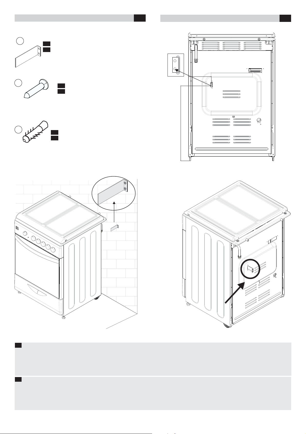
GB
Please apply the following procedure while placing your oven.
1- Place your oven to the place of use and make its height and level adjustments.
2- Determine the H and Y measure as indicated in the figure and mark the wall to which the oven will be fixed. (Figure A)
3- Fix the wall mounting fixture (in the service pouch) on the wall using a dowel and screw (not provided). (Figure B)
4- Push the oven backwards and make the fixture settle in the slot on the back side of the oven. (Figure C)
The fixture will function when inserted 20 mm deep in its slot.
FR
Veuillez respecter la procédure suivante lors de la fixation de votre four.
1- Placez votre four à son lieu d'utilisation puis réglez sa hauteur et son niveau.
2- Déterminez la mesure H et Y comme l'indique la figure, puis faites une marque sur le mur pour identifier l'endroit où le four sera fixé. (Figure A)
3- Fixez le dispositif (dans le sac de service) sur le mur en utilisant un goujon et des vis (non fournis). (Figure B)
4- Poussez le four vers l'arrière et procédez à la fixation dans la rainure, à l'arrière du four. (Figure C)
La fixation n'est effective que lorsqu'elle est d'une profondeur de 20 mm dans sa rainure.
-C-
Page 3

CONTENTS
GB
SOMMAIRE
FR
Safety Instructions
1. General Warnings
1.1. Symbols Used In This User Manual
1.2. Declaration Of Compliance
1.3. Safety Hints
1.4. Useful Tips
2. Installation
2.1. Environment The Appliance Should Be Placed
2.2. Positioning
2.3. Feet Adjustment
2.4. Electrical Connection
2.5. Cookers With Energy Cable
2.6. Cookers Without Energy Cable
2.7. Gas Connection
2.8. Conversion For Different Gas Types
2.9. Dimensions Of The Appliance
2.10.General Appearance And Definition Of The Appliance
3. Use Of Cooktop Burners
3.1. Use Of Cooktop Gas Burners
3.2. Use Of Cooktop Electrical Plates
4. Use Of The Oven
4.1. Grilling
4.2. Electric Oven
4.3. Electric Oven Suggestions For Cooking
4.4. Cooking Pizza
4.5. Cooking Cakes
4.6. Cooking Meats
4.7. Cooking Fish
4.8. Cooking Turn Spit
4.9. Using The Minute Timer
4.10. Using The End Of Cooking Timer
4.11. Gas Oven
4.12. Use Of The Electronic Programmer
4.13. Cooking Tables
5. Cleaning And Maintenance
5.1. Catalytic Self - Cleaning Oven
6. Service Centre & Troubleshooting
7. Protection Of The Environment
...............................................................................................04
............................................................................................05
....................................................................................................05
.....................................................................................................05
........................................................................................................06
......................................................................................................06
.............................................................................................06
.....................................................................................07
..............................................................................................08
................................................................................09
.............................................................................................11
............................................................................................................11
.................................................................................................11
.................................................................................................12
................................................................................................12
................................................................................................12
...................................................................................................12
...........................................................................................13
..................................................................................13
......................................................................................................13
.............................................................................................14
...............................................................05
.............................................................................05
..............................................06
..........................................................................07
......................................................................07
...............................................................08
........................................................................09
.........................................................................09
....................................................................10
.........................................................12
.................................................................13
..............................................................13
.............................................................................15
........................................................................15
.................................................................15
.....................................................................15
................................09
Conseils De Sécurité
1. Recommandations
1.1. Symboles Utilisés Dans La Notice
1.2. Déclaration De Conformité
1.3. Consignes De Sécurite
1.4. Conseils Utiles
2. Installation
2.1. Environnement Dans Lequel L'appareil Doit Être Installé
2.2. Positionnement
2.3. Réglage Des Pieds
2.4. Raccordement Electrique
2.5. Cuisinière Livrée Avec Cordon D'alimentation
2.6. Cuisiniere Livree Sans Cordon D'alimentation
2.7. Raccordement Gaz
2.8. Modification Pour Type De Gaz Différent
2.9. Dimensions De L'appareil
2.10. Aspect Général Et Definition De L'appareil
3. Utilisation Des Brûleurs
3.1. Utilisation Des Brûleurs De La Table De Cuisson
3.2. Utilisation Des Plaques Electriques Sur De La Table De Cuisson
4. Utilisation
4.1. Utilisation Du Four Grill
4.2. Four Electrique
4.3. Suggestions De Cuisson Au Four Electrique
4.4. Cuisson Pizza
4.5. Preparation De Gateaux
4.6. Cuisson De La Viande
4.7. Cuisson Du Poisson
4.8. Cuisson Au Tournebroche
4.9. Utilisation De La Minuterie
4.10. Utilisation Des Bruleurs A Gaz De La Table De Cuisson
4.11. Four A Gaz
4.12. Utilisation Du Programmateur Electronique
4.13. Tableau De Cuisson
5. Nettoyage Et Maintenance
5.1. Four Catalitique Autonettoyant
6. Centre D'assistance Technique Et Résolution Des Problèmes
7. Protection De L’environnement
...........................................................................................16
..........................................................................................17
...................................................................................17
................................................................................................17
........................................................................................................18
...............................................................................................18
.........................................................................................18
.........................................................................................20
..................................................................................22
..........................................................................................................23
....................................................................................................25
...................................................................................23
................................................................................................23
.................................................................................................24
....................................................................................24
.......................................................................................24
.....................................................................................26
..................................................................17
..............................................................................17
...............................18
................................................................................19
...............................................................................21
.................................................................................24
...............................................................................25
..............................................................................25
..............................................................................27
.......................................................................27
.....................................................................28
................................................19
................................................19
........................................................20
...................................................21
...........................................22
..................................................24
..............................25
..................................................25
..................22
...................28
GAS TYPE TABLES ...................................................................................41-42-43
Page 4

SAFETY INSTRUCTIONS
WARNING: The appliance and its accessible parts become hot during use. Care should be taken to avoid
touching heating elements.
• Children under 8 Year of age must be kept away from the appliance unless they are continuously
supervised.
• This appliance can be used by children aged from 8 years and above and persons with reduced physical,
sensory or mental capabilities or lack of experience and knowledge if they have been given supervision or
instruction concerning use of the appliance in a safe way and understand the hazards involved.
• Children must not play with the appliance.
• Cleaning and user maintenance shall not be made by children without supervision.
WARNING: Unattended cooking on a hob with fat or oil can be dangerous and may result in fire.
NEVER try to extinguish a fire with water, but switch off the appliance and then cover flame e.g. with a lid or
a fire blanket.
WARNING: Danger of fire: do not store items on the cooking surfaces.
• During use the appliance becomes hot. Care should be taken to avoid touching heating elements inside
the oven.
WARNING: Accessible parts may become hot during use. Young children must be kept away.
• Do not use harsh abrasive cleaners or sharp metal scrapers to clean the oven door glass since they can
scratch the surface, which may result in shattering of the glass.
• The internal bottom surface of the drawer can get hot.
• The oven must be switched off before removing the guard, after cleaning, the guard must be replaced in
accordance with the instructions.
• Only use the temperature probe recommended for this oven.
• Do not use a steam cleaner for cleaning operations
• Any spillage should be removed from the lid before opening.
• The hob surface must be allowed to cool down before closing the lid.
WARNING: Avoid possibility of electric shock - ensure the appliance is switched off before replacing the
lamp.
• If the range is placed on a base, measures must to be taken to prevent the appliance slipping off the base.
• A mean for disconnection from the supply mains having a contact separation in all poles that provide full
disconnection under overvoltage category III conditions, must be incorporated in the fixing wiring in
accordance with the wiring rules.
• The instructions state the type of cord to be used, taking into account the temperature of the rear surface
of the appliance.
• If the supply cord is damaged, it must be replaced by a special cord or assembly available from the
manufacturer or its service agent.
CAUTION: In order to avoid a hazard due to inadvertent resetting of the thermal cutout, this appliance must
not be supplied through an external switching device, such as a timer, or connected to a circuit that is
regularly switched on and off by the utility.
• This appliance must be installed in accordance with the regulations in force and only used in a well
ventilated space. Read the instructions before installing or using this appliance.
• These instructions are only valid if the country symbol appears on the appliance. If the symbol does not
appear on the appliance, it is necessary to refer to the technical instructions which will provide the
necessary instructions concerning modification of the appliance to the conditions of use of the country".
• Prior to installation, ensure that the local distribution conditions (nature of the gas and gas pressure) and
the adjustment of the appliance are compatible.
• The adjustment conditions for this appliance are stated on the label (or data plate).
• This appliance is not connected to a combustion products evacuation device. It shall be installed and
connected in accordance with current installation regulations. Particular attention shall be given to the
relevant requirements regarding ventilation.
• The use of a gas cooking appliance results in the production of heat and moisture in the room in which it is
installed. Ensure that the kitchen is well ventilated: keep natural ventilation holes open or install a
mechanical ventilation device (mechanical extractor hood). Prolonged intensive use of the appliance may
call for additional ventilation, for example opening of a window, or more effective ventilation, for example
increasing the level of mechanical ventilation where present.
CAUTION: Accessible parts may be hot when the grill is in use. Young children must be kept away".
WARNING: In order to prevent tipping of the appliance, stabilizing means must be installed. Please refer to
the instructions on page 02 of this manual.
04 GB
Page 5
1. GENERAL WARNINGS
Thank you for choosing one of our products. To get the most out of
your cooker we recommend that you:
•Read the notes in this manual carefully: they contain important
instructions on how to install, use and service this cooker in safety
Keep this booklet in a safe place for easy, future reference.
•In the case of the sale or transfer of the appliance, this manual should
be given together with the appliance in order to guarantee the proper
transfer of the information on installation/usage of the appliance and
the relative warnings .
•Take care to not touch these elements. When the cooker is first
switched on it may give off acrid smelling fumes-this smoke is
harmless we suggest to operate the cookers for 2 hours while empty.
1.1. SYMBOLS USED IN THIS USER MANUAL
For easier comprehension, the symbols below are used in this user
manual.
Safety Information
Information for Environment Protection
This appliance complies with the EU E.E.C directives.
Caution, possibility of tilting.
Anti-tip restraints.
inexistent or insufficient, an extractor fan must be installed. If in doubt,
please apply to a GIAS Service for advice.
•When using any electrical appliance you must follow a few basic
rules:
*It is not generally a good idea to use adapters, multiple sockets for
several plugs and cable extension.
*Do not pull the power cable to remove the plug from the socket.
*Do not touch the oven with wet or damp hands or feet.
*If the main cable is damaged it must be replaced promptly:
*When replacing the cable, follow the instructions given below:
*Cable replacement must be carried out by qualified technicians. Use
only an approved service centre for repairs end ensure that only
original parts are used.
*When necessary, remove the power cable and replace it with one of
the H05RR-F, H05VVF, and H05V2V2-F type. The cable have the
capacity for the electrical current required by the product.
•Check the flexible gas connection pipe periodically.
•The gas inlet hose must be kept away from the hot parts of the oven
and must not come into contact with the oven. You can move the gas
inlet connector to the left or to the right of the oven. After such a
modification, check for possible gas leakage with a soapy solution.
•After attaching the gas pipe to the connector, anchor it firmly with a
clamp. Particular attention must be paid for gas leakage: check with a
soapy solution.
•Do not leave the appliance unattended before it has cooled down.
If the above instructions are not adhered to, the
manufacturer cannot guarantee the safety of the cooker.
1.2. DECLARATION OF COMPLIANCE
This equipment, in the parts intended to come into contact with food,
complies with the regulations laid down in EEC directives 89/109.
The appliance complies with European Directives 2009/142/EC and
subsequent amendments.
By placing the mark on this product, we are confirming
compliance to all relevant European safety, health and environmental
requirements which are applicable in legislation for this product.
1.3. SAFETY HINTS
•The cooker must be used only for the purpose for which it was
designed: it must only be used for cooking food. Any other use, e.g. as
a form of heating, is improper use of the cooker and is therefore
dangerous.
•The manufacturers cannot be held responsible for any damage
caused by improper, incorrect or unreasonable use.
•When using any electrical appliance you must follow a few basic
rules. If the appliance breaks down or develops a fault switch it off,
disconnect it from mains, do not touch it, call the authorised Service.
•Do not insert your hand between oven and the upper lid hinges. Keep
children away.
•Make sure that all the knobs are in the OFF position when the
appliance is not in use.
•The oven drawer is to store empty trays or to keep food warm.
•Do not put flammable, explosive or cleaning materials like nylon
bags, paper, cloths, etc, into the drawer.
•Use only heat resistant pots and pans . Do not use flammable
materials.
•It is dangerous to modify or to attempt to modify the properties of
the appliance.
•Particular attention is necessary when you are frying: do not leave the
appliance unattended.
•The appliance is heavy. Take care when moving.
• The emission of hot air is normal while the appliance is working. Do
not close the vents on the oven.
•Some spillage on the appliance may occur, when placing food on or
into the appliance or when removing food with excess fat or water.
Clean such residues immediately after cooking, in order to prevent
unpleasant smells and possible fires.
•Either reduce the flame or shut down the burners, before removing
pans.
• WARNING! Heat and humidity are produced in the area where
appliances which burn gaseous fuels are used. Special attention must
be paid for correct aeration of the environment: if natura ventilation is
1.4. USEFUL TIPS
If your appliance has a top lid, it is designed for either protecting the
cook top against dust when it is not functioning or to prevent against oil
spillage during cooking.
•Do not use the lid for other purposes.
•ATTENTION! (For models with glass lid) The glass lid can break if it is
exposed an excessive heat. Always check that the burners are off
before closing the lid.
•Do not use deformed or unbalanced pans.
•Clean the grill and the fat collecting tray carefully before initial usage.
•When using cleaning sprays, do not spray on heaters or on the
thermostat.
•Make sure that oven shelves are correctly placed.
•Light the burner before placing the pan on top for quicker ignition.
•Check the burner for a normal flame.
•Do not cover oven parts with aluminium foil.
05 GB
Page 6
2. INSTALLATION
Installation have to be made by qualified personnel. The manufacturer
have no obligation to carry this out. If the assistance of the manufacturer is
required to rectify faults arising from incorrect installation, this assistance
is not covered by the guarantee.
The installation instructions for professionally qualified personnel must be
followed. Incorrect installation may cause harm or injury to people,
animals or belongings. The manufacturer cannot be held responsible for
such harm or injury.
WARNING! Care must be taken regarding where the appliance is placed!
It can only be installed in a continuously ventilated room.
Electrical connections must always be disconnected before any repair,
installation or modification.
The use of a gas cooking appliance results in the production of heat and
moisture in the room in which it is installed. Ensure that the kitchen is well
ventilated: keep natural ventilation holes open or install a mechanical
ventilation device (mechanical extractor hood). Prolonged intensive use
of the appliance may call for additional ventilation, for example opening of
a window, or more effective ventilation, for example increasing the level of
mechanical ventilation where present.
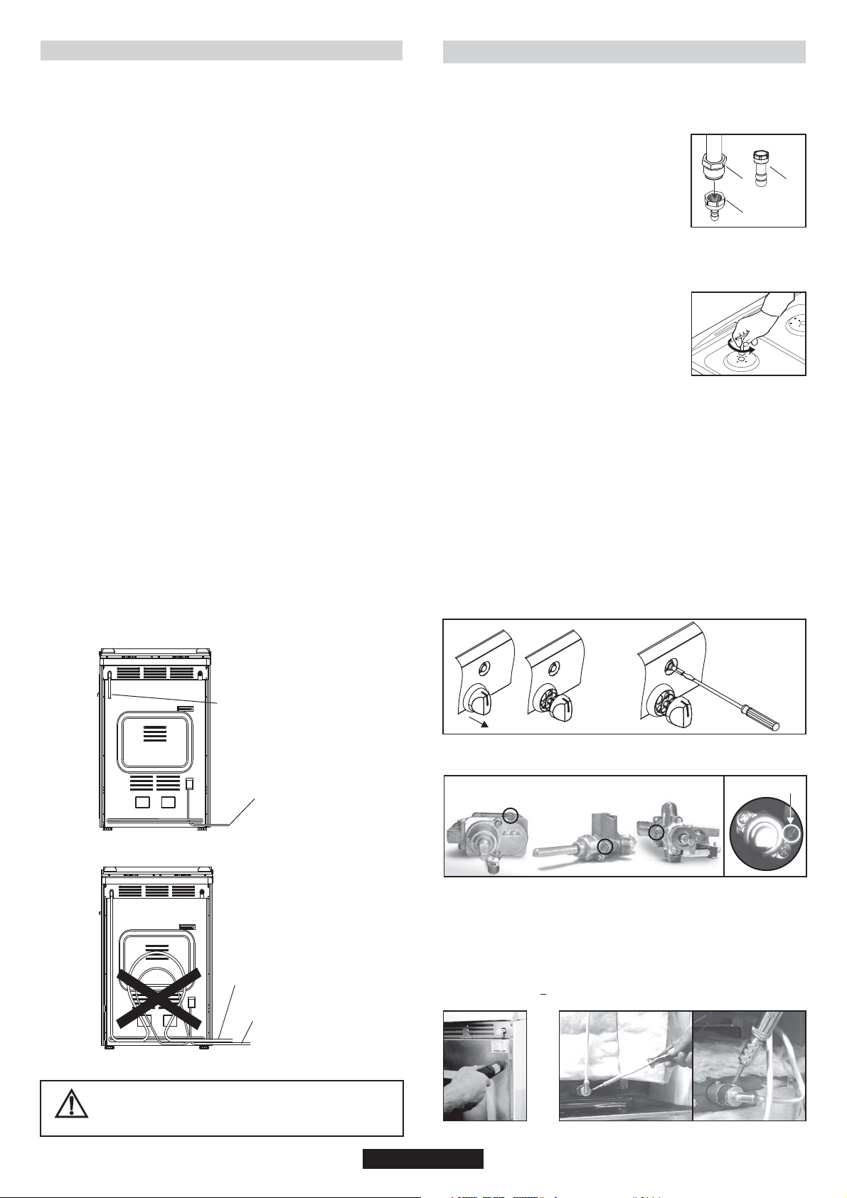
•Before positioning your appliance, check the properties of the energy
supply (gas type, gas pressure) and make sure that your appliance is
regulated accordingly.
•This appliance must not be connected to the exhaust system of any
equipment running on other fuel.
•The appliance must not be installed near flammable materials (e.g.
furniture, curtains, etc.)
•If the range is placed on a base, measures have to be taken to prevent the
appliance slipping from the base.
2.1. ENVIRONMENT THE APPLIANCE
SHOULD BE PLACED
•The appliance must not be placed on a base
•There must be sufficient natural air ventilation in the room for gas
combustion for the appliance to function correctly.
•The air flow should enter through grilled air vents in the outer walls.
•This grill(s) should be constructed so that it cannot be closed from
either side and positioned preferably near the floor. Grill(s) must not be
placed across the channels through which combustion gases and
exhausted fumes pass.
•If it is impossible to install grilled air vents in the room where the
appliance is installed, the air needed can also be supplied from an
adjacent room providing it is not a bedroom or a room where an air
current could cause danger.
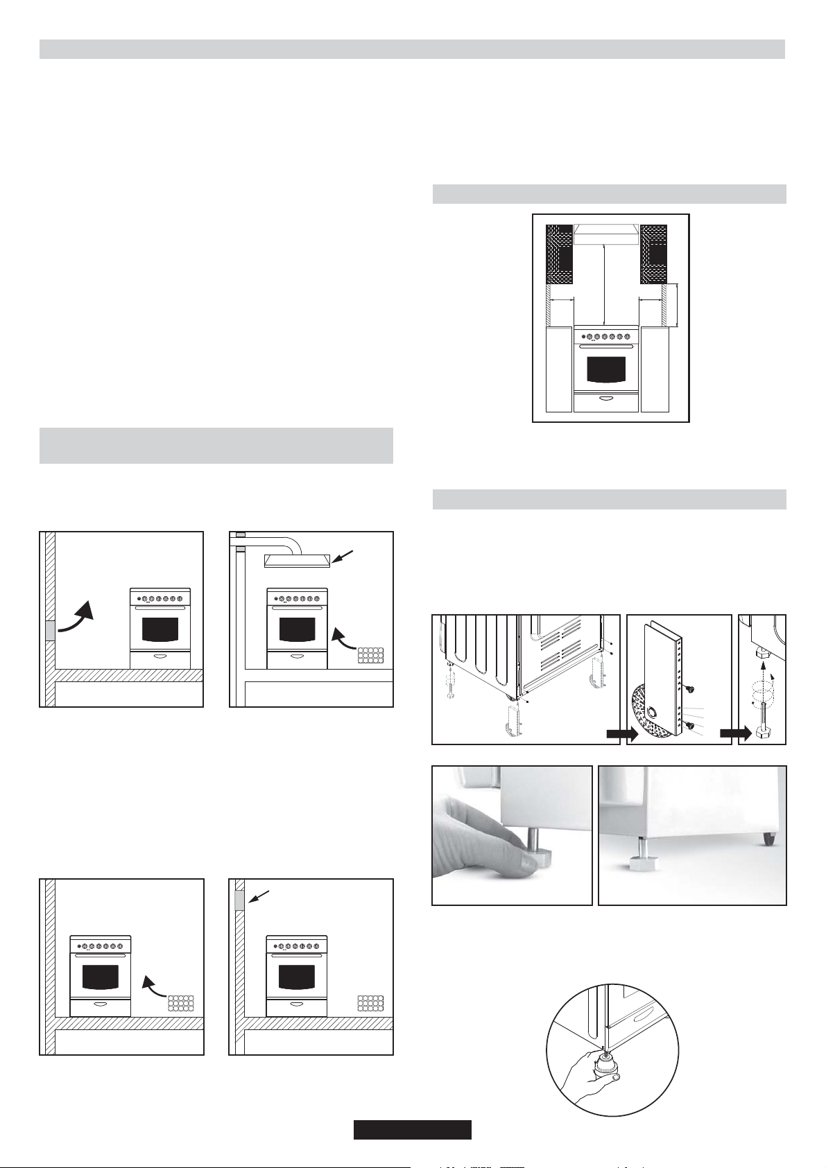
2.2. POSITIONING
200 mm 200 mm
This appliance is “Class 2.1”. The appliance has been designed on
the presumption that the adjacent work tops will be no higher than the
cook top surface.
750 mm
400 mm
2.3. FEET ADJUSTMENT
Your appliance has adjustable feet at the lower corners of its chassis.
•The feet can be adjusted individually with the aid of a wrench to
guarantee that the oven is perfectly balanced and levelled, so that any
liquids in the pans is horizontal .
•Air grills must have a cross section of 100 cm² for the passage of air and
for appliances with a flame safety device. For appliances with no flame
safety device, this cross section should be 200 cm². (Single or multiple
grills can be used)
Emission of Combustion Gases
•Combustion gases from cooking appliances must be released directly out
of doors or via a hood connected to a chimney or flue (Figure 1)
•If it is impossible to install a hood, an electric extraction fan should be fitted
in a wall or a window opening out of doors (Figure 2)
•Extractor fans should have a capacity of replacing kitchen air 3- 5 times
per hour.
Adjustable feet and wheels.
AA1
A2
4
3
2
1
CB
•The maximum height of cooker will be 868mm by fixing the adjustable
front feet and rear wheels to the 4th hole.
•Rear wheels should be fixed to the 2nd hole (picture A1), standard
height. Thus, standard height will be 850 mm.
Adjustable feet.
Figure 1 Figure 2
06 GB
Page 7
2.4. ELECTRICAL CONNECTION
2.6. COOKERS WITHOUT ENERGY CABLE
Cookers can be presented with or without enrgy cable. Cable
connection should be done by Autorited service according to
following instructions.
The electrical connection must be made according to the standards
and regulations in force. Before making the electrical connection,
check the following:
•Is the capacity of the electrical connections and safety fuses in the
building sufficient to cope with the load of the appliance? (Check with
the adhesive info label)
•Does the electricity supply line have an earth connection conforming
with the standards in force? A proper earth connection must exist in
your home. If there is not a proper earth connection at your home,
please apply to an authorized technician to deal with this problem.
•Is the socket or the multi-pole switch at a easily reachable point after
the installation of the appliance?
•A plug conforming to standards should be connected to the mains
cable and the cable should be inserted into a safe socket.
•A multi-pole switch must be used between the appliance and the
electricity line if a direct electrical connection to the appliance is
required. (It must comply with standards and be appropriate for the
load)
The green-yellow ground cable must not be interrupted by a switch.
The brown phase cable (from the “L" coded connector of the oven)
must always be connected to the phase line of the mains.
•The power line must be positioned so that it is not exposed to
temperatures higher than 50° C.
•When the power cable must be changed, a cable with a cross section
appropriate to the indicated power must be used. The green-yellow
ground cable should be approximately 2 cm longer than phase and
neutral cables.
•Check the heaters by switching them on for 3 minutes, after having
completed the connection.
•The manufacturer will not accept responsibility for damages
arising due to non-compliance with the safety standards.
•For the direct connection to the fixed wiring, it’s nessessary to provide
means for disconnection from the supply mains having a contact
separation in all poles that provide full disconnection under
overvoltage category III conditions, in accordance with the wiring
rules
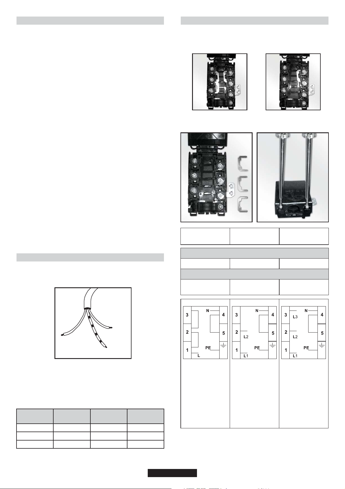
Cable box connection types
1- Monophase connection
2- Three-phase connection
Attention: A poor clamping can draw away risks dangerous
heating at the level of the cable feeding
Monophase
220-240 V~
Two-phase
380-415V2N~
Three-phase
380-415V3N~
2.5. COOKERS WITH ENERGY CABLE
•Connection is exclusively envisaged under tensions of 220-240V
Between phases or between phases and neutral.
Neutral
Phase cable
(brown)
Ground cable (Green-Yellow)
•The eventual replacement of the supply cord must be carried on by
the After Sales Service or by an agreed engineer, with a cord whose
characteristics must be similar to the original one
Ratings/Supply Cable Sections:
Model rated
power (kW)
2.3 kW
3.5 kW
4.0 kW
Rated Voltage
(V)
220 - 240 V
220 - 240 V
220 - 240 V
(blue)
Rated Current
(A)
9.1 A
15.9 A
18.2 A
Supply Cable
3 x 1.0 mm
3 x 1.5 mm
3 x 2.5 mm
2
2
2
3 G 4 mm
2
H05VV-F
H05RR-F
L1 : Phase
shunt 1-2 and
shunt 2-3
N : Neutral
shunt 4-5
PE Earth
Cable - Section
4 G 1.5 mm
2
Cable - Type
H05VV-F
H05RR-F
1 Phase
2 Phase
5 Neutral
shunt 4-5
PE Earth
5 G 1.5 mm
H05VV-F
H05RR-F
1 Phase
2 Phase
3 Phase
5 Neutral
shunt 4-5
PE Earth
2
07 GB
Page 8
2.7. GAS CONNECTION
2.8. CONVERSION FOR DIFFERENT GAS TYPES
The gas must be connected to the appliance according to standard
and the provisions in force.
•When the appliance left the factory, it was regulated for the gas type
stated on the adhesive info label near the gas inlet at the back of the
appliance.
Make sure that you are using the gas stated on the label. If it is a
different type of gas, follow the instructions in the chapter on
conversion to different gas types'.
•Make sure that gas supply pressure is that given in the gas type
category table (Last 3 pages in this user manual) in order to achieve
maximum efficiency and lowest consumption. If the gas pressure is
different, a proper gas regulator should be used on the gas inlet. The
use of a gas regulator complying with the standards for LPG is
allowed.
Connection with a Solid or Flexible Metal Pipe
•The gas supply can be connected by a proper flexible stainless steel
pipe according to the safety standards in force. In this case, there will
be no further need to move the appliance. The gas inlet connector of
the appliance is Gc ½.
Connection with a Flexible Non-metallic Pipe
•If the gas connection is in a position where it can be switched on and
off when required, a flexible pipe complying with the standards in force
can be used. The flexible pipe must be firmly fixed with a clamp.
•The flexible pipe can be connected as follows:
•Since the flexible pipe will be placed behind the oven, it should be
exposed to temperatures no higher than 30ºC at any point.
•The length should be no longer than 150 cm.
•It must not be exposed to steam.
•No folding, bending or tension is allowed.
•It should be protected against sharp or piercing objects.
•It must be accessible in order to allow for periodic inspection.
•The flexible pipe must be checked as follows to guard against wear
over time:
•Check that there are no cracks, cuts or burned spots on or at the ends
of the pipe.
•The material must maintain its flexibility . Excessive rigidity is not
allowed.
•There must be no rust on the clamps.
•It should be replaced in any case after no more than 5 years' usage.
For the cookers below written adjustment have to be done by qualified
technician.
Follow the steps given below to convert the appliance from the factory
set up to that for a different gas type.
Cookers are adjusted NG and connection type
is cylindric (1). For hose type NG connection,
hose adapter (2) can be fixed to cylindrical
adapter with seal.
For LPG connection, LPG hose adapter (3) can
be fixed to cylindric adapter with seal.
Adjustments and changing injectors
Changing Injectors
•Remove grates.
•Remove burner caps and burners.
•Remove injectors by using a 7 mm wrench, then screw on the correct
injector selected from gas type category table
(last 3 pages in this user manual) according to
the gas to be used.
•Follow the above steps in the reverse order
after completing the assembly of the new
injector.
Stand by Adjustment
Stand by adjustment for the cookers
without safety devices and with safety devices and button
ingition
•Turn the burner control knob to the small flame position and remove
the knob.
•If conversion from natural gas to LPG is required, turn clockwise the
by-pass screw of the gas valves with a screw driver to their final
position.
•If conversion from LPG to natural gas is required, turn anti-clockwise
the by-pass screw of the gas valves with a screw driver till a smaller
flame of ¼ size is obtained.
•After completing the adjustment, insert the knobs again.
•Check the adjustment by turning the burner control knob quickly from
maximum to minimum position. If the flame does not go out, it means
that the adjustment is correct.
•For safety devices, idle flame setting can be done with screw on valve
body. If there is ignition on the knob for idle flame setting cooktop,
toplid and panel must be removed.
1
3
2
RIGHT
FLEXIBLE GAS PIPE LINE
ELECTRICAL CABLE
WRONG
FLEXIBLE GAS PIPE LINE
ELECTRICAL CABLE
without safety
devices
•For thermostat valve idle frame setting cooktop, top lid and panel
must be removed.
By-pass screw for the burner
Gas Oven
•Remove rear cover ( Figure3)
•Remove injector adapter.(Figure 4)
•Remove injectors by using a 7 mm wrench, then screw on the correct
injector selected from gas type category table (last 3 pages in this
user manual) according to the gas to be used. (Figure 5)
•Follow the above steps in the reverse order after completing the
assembly of the new injector.
•Burner Gap is 4.5 + 0.3 mm for NG and LPG (Figure 6)
safety devices
Check all connections for leaks with a soapy substance
after the installation is completed. Do not use a flame
for to check gas leaks.
Figure3 Figure4
08 GB
Page 9
4.5 + 0.3
Figure5 Figure6
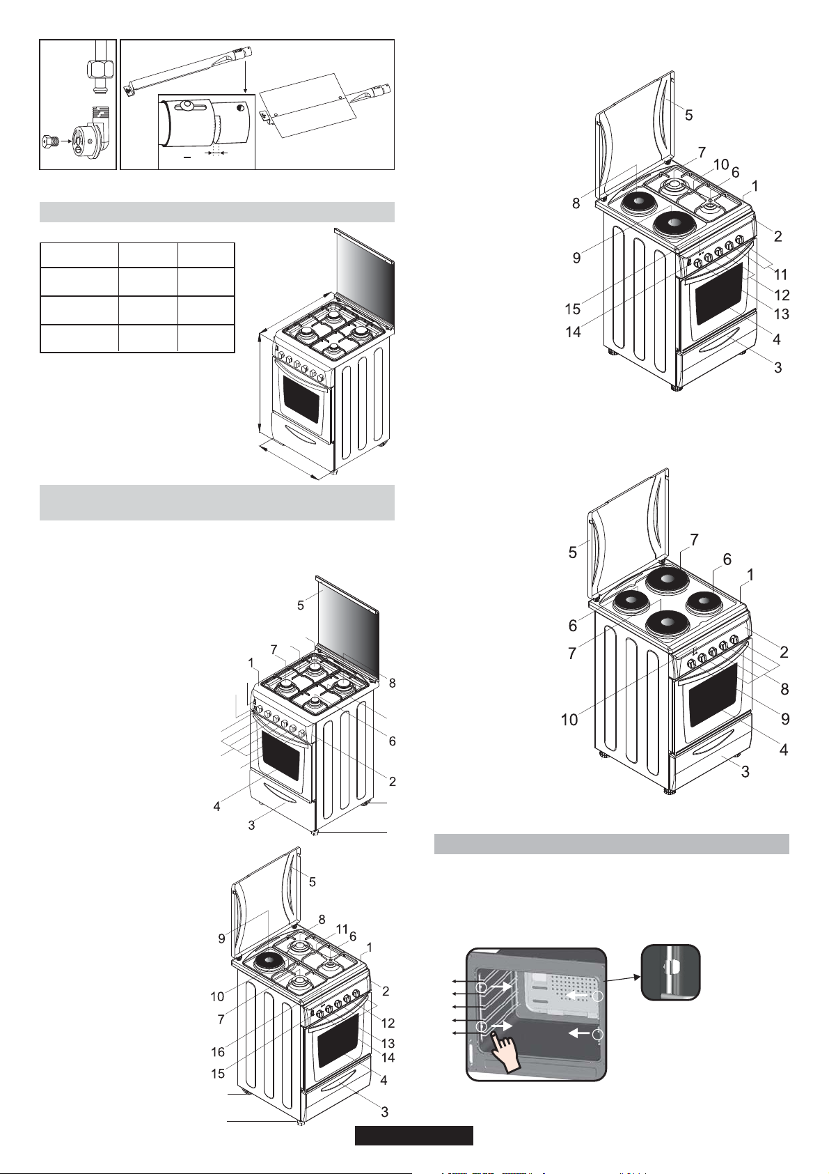
2.9. DIMENSIONS OF THE APPLIANCE
50 x 60
60 x 60
Cook top
1-
Control panel
2-
Drawer
3-
Oven door (Front door)
4-
Metallic top lid or Glass top lid
5-
Auxilary burner
6-
Rapid burner
7-
Hot plate
8-
Hot plate
9-
Right grate
10-
Burners control knobs
11-
Hot plates control knobs
12-
Thermostat oven knob
13-
Ignition button or fan button
14-
Signal lamp
15-
Height (mm)
Width (mm)
Depth (mm)
863
510
600
850
598-600
600
D
H
W
2.10. GENERAL APPEARANCE AND DEFINITION
OF THE APPLIANCE
This User Manual has been drawn up as a guide for several models.
Some of the properties mentioned in this manual may not exist in your
appliance.
Cook top
1-
Control panel
2-
Drawer
3-
Oven door (Front door)
4-
Glass top lid or metallic top lid
5-
Auxilary burner
6-
Rapid burner (Semi-Rapid burner)
7-
Ultra rapid burner (Rapid burner)
8-
Semi-Rapid burner
9-
Left grate
10-
Right grate
11-
Burners control knobs
12-
Thermostat oven knob
13-
Ignition button or fan button
14-
Lamp knob
15-
Timer knob
16-
Moving Foot (Adjustable Feet)
17-
Bolt Foo t(Adjustable Feet)
18-
14
15
13
12
16
10
9
11
17
18
Cook top
1-
Control panel
2-
Drawer
3-
Oven door (Front door)
4-
Metallic top lid or Glass top lid
5-
Hot plate
6-
Hot plate
7-
Hot plate control knobs
8-
Thermostat oven knob
9-
Signal lamp
10-
REMOVING AND CLEANING WIRE RACKS
1-
Cook top
2-
Control panel
3-
Drawer
4-
Oven door (Front door)
5-
Metallic top lid or Glass top lid
6-
Auxilary burner
7-
Rapid burner (Semi-Rapid burner)
8-
Ultra rapid burner (Rapid burner)
9-
Hot plate
10-
Left grate
11-
Right grate
12-
Burners control knobs
13-
Hot plate control knob
14-
Thermostat oven knob
15-
Ignition button or fan button
16-
Signal lamp
17-
Moving Foot (Adjustable Feet)
18-
Bolt Foot (Adjustable Feet)
1- Remove the wire racks by pulling them in the direction of the arrows
(see below)
2- To clean the wire racks either put them in the dishwasher or use a
wet sponge, ensuring that they are dried afterwards.
3- After the cleaning process install the wire racks in reverse order.
5
4
3
2
1
17
18
09 GB
Page 10
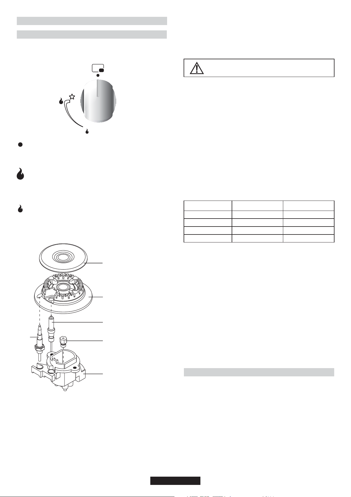
3. USE OF COOKTOP BURNERS
3.1. USE OF COOKTOP GAS BURNERS
The knobs which control the burners are positioned on the control
panel.
Figure 7
Off Position
When the knob is turned so that the 'dot' symbol faces towards
the panel, it is in the Off position and the gas valve is closed and
the flame will go out.
Maximum Gas Flow
Press the burner knob and turn it to the left till the 'dot' symbol
faces towards the large flame symbol.
The flame is on full at this position.
In this position, the gas valve is completely open.
Oven Gas Burners
The button must not be kept pressed down for more than 15 sec. If the
burner has not ignited after 15 sec. release the button and open the
compartment door and/or wait at least 1min. before attempting again.
For other models the gas is ignited by means of the control knobs.
Make sure that the gas is actually burning after this
step! If there is no flame, repeat the procedure
After ignition, adjust the flame to the size required.
Manual ignition (if the electricity supply is not available)
Hold a flame (a match or a lit taper or a hand-operated gas lighter),
near the burner.
WARNING! to wait 1 minute between two ignition tentative.
Press and turn the knob of the burner you want to ignite as far as the
large flame symbol. If the burner does not catch fire at the first attempt,
try again pressing the knob a little longer. When the burner is lit, adjust
the flame to the required level.
If the burner does not light after several attempts, check the correct
position of the burner and its cap.
Turn the knob clockwise to the “O” position in order to close the gas
flow. If the burner accidentally stops burning, wait at least one minute
before attempting to relight it.
Some cookers have a flame safety device (see the picture above,
safety device F). If the flame goes out, the gas supply is automatically
cut off.
Minimum and maximum diameters of the cooking pan bases :
Minimum Gas Flow
The flame can be decreased by turning the knob so that the 'dot'
symbol faces towards the small flame symbol. The valve will be
partially open and the burner will then be on low.
A - Burner Lid
B - Burner
A
C - Electrode
D - Injector ( Jet )
E - Burner body
F - Safety device
B
C
F
D
E
Figure 8
Burner
Auxiliary Burner
Semi Rapid Burner
Rapid Burner
Ultra rapid Burner
•The outer surface of the flame is hotter than the inner part. The tips of
the flames must touch the bottom of the pan. Flames extending
outside the pan cause unnecessary gas consumption.
•Gas burners, unlike the electrical hot plates, do not need flat
bottomed pans. Flames touching the base of the pan conduct the heat
completely.
•Although there is no need for special pans for gas burners, pans
made of thinner material conduct the heat faster than those in thicker
material.
•Some parts of the food may be heated while others remain cold due
to the uneven distribution of heat under the pan. Therefore,
continuous stirring of the food being cooked is necessary in the case
of thin-bottomed pans. Heat is more effectively and evenly distributed
with thick-based pans.
•Use of very small pans is not recommended. Wider, low-sided pans
are more suitable for more effective and quicker cooking than small,
deep pans.
•You cannot shorten cooking time by using a small pan over a large
burner. You will only waste gas in this way. However, a pan with a lid
will save energy.
Min. Diameter [mm]
Ø 240 mm
Ø 180 mm
Ø 120 mm
Ø 240 mm
Max. Diameter [mm]
Ø 280 mm
Ø 240 mm
Ø 180 mm
Ø 280 mm
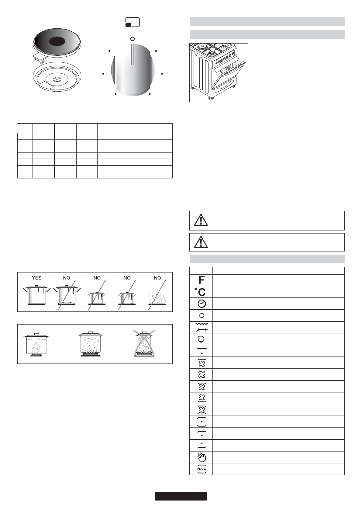
3.2. USE OF COOKTOP ELECTRICAL PLATES
Ignition of the Burners
Cooktop Gas Burners
The burner must be ignited before a pan is placed over it.
For models with automatic ignition, the 'spark' button must be
pressed.
Press the knob controlling the burner you want to ignite and then turn it
left to the big flame symbol. Press the ignition button. On models with
ignition-thru knobs, press and turn the knob controlling the burner you
want to ignite as far as the star symbol; the electrode will be
automatically activated. All the electrodes will be activated
automatically and the burner to which gas is supplied (that relative to
the knob pressed) will ignite.
Turn the knob to the position for the required temperature of the hot
plate. The indicator light of the hot plate will come on and the hot plate
will start to heat.
When cooking is completed, turn the knob to the “O” position. Do not
leave the hot plate turned on without a pan on it. The diameter and the
base of the pan you use is critical. The minimum diameter of the pan
base is 14 cm and the base should be flat.
Leave the hot plate to heat up for 5 minutes before placing a pan on it
the first time you use it. This will allow the heat resistant coating of the
plate to harden due to burning.
Use a wet cloth and detergent for cleaning the hot plates. Do not
remove food residues from the hot plates with a knife or any other
hard, sharp object.
Turn on the hot plate for a few moments to dry it after cleaning.
However, it must never be left on for more than a few moments without
a pan on top.
10 GB
Page 11
Hilight
4. USE OF THE OVEN
4.1. GRILLING
6
5
4
Figure 9 Figure 10
Position
0
1
2
3
4
5
6
Power
(Watt)
0
100 W
180 W
250 W
500 W
750 W
1000 W
Power
(Watt)
0
135 W
220 W
300 W
850 W
1150 W
1500 W
Power
(Watt)
0
175 W
220 W
300 W
850 W
1150 W
2000 W
1
2
3
Explanation
Off
Heating
Cooking at low temperature
Cooking at low temperature
Cooking, Roasting, Boiling
Cooking, Roasting, Boiling
Cooking, Roasting, Boiling
Suitability of Cooking Pans
Keep in mind that larger pans have larger heating surfaces.
This will help them to cook the food faster than pans with smaller
heating surfaces.
Always use pan sizes proportionate to the amount of the food to be
cooked. In order to prevent splashing, do not use very small pans,
especially for foods with excess liquid. If you use excessively large
pans for quick cooked foods, sausages and liquids will stick and
residues will remain attached to the pan after being emptied.
Closed pans and baking trays or moulds are suggested for cooking
sweets. Splashed sugar and juices from an open pan may stick to the
cooker surface and will be difficult to remove.
ELECTRIC GRILL: Use with closed door
ONLY
GAS GRILL: It can be used with open door
WITH panel protector inserted under control
panel, as in picture.
•Grilling gives food a rich brown colour
quickly. Depending on the quantity of the
food, you can switch the grill on to different
positions. Almost all food can be cooked
under the grill except for very lean game and
meat rolls.
•Meat and fish that is going to be grilled should first be lightly doused with
oil.
•Place a fat collecting tray beneath during grilling. Put some water into the
tray to prevent unpleasant smells and to prevent the fat catching fire.
•Grilling is usually preferred for cooking pieces of meat, for example
steaks, which are not too thick, different sized meat parts, cleaved hunted
birds, fish, some vegetables (e.g. courgettes, aubergines, tomatoes, etc.)
together with meat and fish products on spits.
Oil the fish lightly before putting it directly under the grill.
Add salt on meat after cooking, salt fish into the cleavage before cooking.
•The distance from the grill will depend on the thickness of the meat or fish.
If the distance is correctly judged, the outer parts will not be burnt and the
inside will not remain raw.
•Prevent unpleasant odours and smoke caused by dripping fats and
sauces by pouring 1-2 glass of water into the fat-collecting tray.
•You can also use the grill for toasting, toasted bread or sandwiches, for
example, and also to cook certain fruits (bananas, grapefruit or pineapple
slices, apples etc.). However, fruit must not come into contact with the
heating elements.
Never cover oven inner walls or the bottom with
aluminium foil. Accumulated heat can damage the oven
enamel and your meal.
While the oven functions are running, top lid of the
cooktop must be open position.
4.2. ELECTRIC OVEN
Position
Function
Oven Function
Figure 11
Figure 12
This is especially important for pans used for roasting or pressurized
cooking at high temperature.
Do not leave burners unattended without a pan or with an empty pan
on top.
Check the suitability of cooking pans with respect to the following
criteria;
They should be heavy.
They should completely cover the burner surface; they may be a little
bigger but no smaller.
Base surfaces should be completely flat and fit well on the cooking
surface.
•For the best use of the electric hotplates and to minimize energy
consumption, only pans with smooth flat bases should be used. The
size of the pan should be as close as possible to the diameter of the
hotplate, and never smaller. The base of the pan should be dry and
spillage should be avoided. Empty pans must not be left on the plates,
and the plates should not be left switched on without a pan.
Temperature
Cooking time
Not in function
Turn spit and grill heater
Lamp
Grill heater
Grill heater and fan
Fan
Upper heating element and fan
Lower heating element and fan
Upper heating element, lower heating element and fan
Lower and upper heating element
Upper heating element
Lower heating element
Manual
Pizza
11 GB
Page 12

4.3. ELECTRIC OVEN SUGGESTIONS FOR
COOKING
Traditional Cooking
Heat is generated from the upper and lower heaters. Generally, the
middle shelf position is preferable for cooking. However, if the top or
bottom surface of the food must be cooked more, place it on the upper
or lower shelf.
Convection Cooking (with Fan)
•The food is cooked by evenly distributed preheated air blown into the
oven by the help of the fan located on the inside back wall of the oven.
It is possible to cook several dishes simultaneously on different
shelves thanks to the evenly distributed heat inside the oven.
•This type of oven is also very useful for defrosting frozen food. It can
also be used for sterilizing canned food, preparing fruit syrups, and
dehydrating fruits and mushrooms.
4.4. COOKING PIZZA
•Thermostat setting at maximum
•Preheating time 15 min (20 min if possible)
•Position of the tray in either one of the two lowest position
•Cooking time 20 min.
4.5. COOKING CAKES
•Unless otherwise suggested, preheat the oven for at least 10 minutes
before use. Do not open the oven door when cooking cakes otherwise
they will not rise (cakes or dishes with yeast and soufflés). The blast of
cold air which will enter the oven will prevent rising. You can check
whether cakes are properly cooked by inserting a rod into the dough. If
the rod comes out dry when you pull it out, it means that the cake is
properly cooked. Do not check in this way until at least three quarters
of the cooking time has elapsed.
Please keep in mind the following tips
•If the surface of the food is cooked well but it is still raw or partly raw
inside, it must be cooked longer at a lower temperature.
•On the other hand, if the surface of the food is too dry, it should be
cooked at a higher temperature for a shorter time.
4.6. COOKING MEATS
•The minimum quantity of meat to be cooked in the oven is 1 kg.
Otherwise, the meat will be too dry.
If you require well done meat, use less fat. If meat has a little fat, there
is no need to use oil. If one side of the meat is fatty, place this side up.
The melted fat will sufficiently grease the part below. Red meats
should be taken out of the fridge at least 1 hour before the cooking.
•Otherwise the meat may become tough due to the temperature
difference. Do not use salt before cooking, especially when grilling
meat. Salt will draw the blood and juices out of the meat which will
consequently prevent the roasting of the upper surface of the meat.
•Add salt to roast meat only after half of the cooking time has elapsed.
•Place the meat to be roasted in a wide, shallow pan.
•Deep sided containers / pans act as a shield against the heat. Meat
can be placed in the oven in a heat resistant pan or directly onto the
grill. Insert a fat / gravy collecting tray beneath the grill. Sauces must
be added at the beginning if the food is cooked for a short time, while it
would be better to add sauces in the last half hour if the food is cooked
for a longer time.
4.7. COOKING FISH
Small fish can be cooked at the maximum temperature from start to
finish. Medium sized fish must be cooked at the maximum
temperature at the beginning and then the temperature must be slowly
reduced. Larger fish must be cooked at lower temperatures from start
to finish. Check the cut at the bottom of fish to understand whether it is
cooked properly. In order to understand whether the fish properly
grilled or not, check the cleavage at the bottom of the fish. The colour
(for grilled fish) should be an even matt white. This is not the case for
salmon and trout.
12 GB
Page 13
4.8. COOKING TURN SPIT
•The cooker is equipped with a metal turnspit, two forks and a hook
used to support the spit.
•Instruction for use:
-Remove all accessories from the oven;
-put the deep pan on the bottom of the oven or on the lowest bench;
-stick the turnspit through the meat, centered between the two forks;
-Fix the turnspit into the drive hole located in the bottom wall, then
hang
the support hook in the drive located at the top front of the oven cavity
and around the edge of the turnspit
•Preheating is not necessary with the turnspit.
•Cooking Time Recommended in turnspit Position
Cooking time (min)
Type of food
Beef (1kg)
Lamb, sheep (1kg)
Veal, Poultry (1kg)
Pork (1 kg)
Gas Oven
25/35
35/45
65/75
60/70
Electric oven
20/30
30/40
60/70
65/75
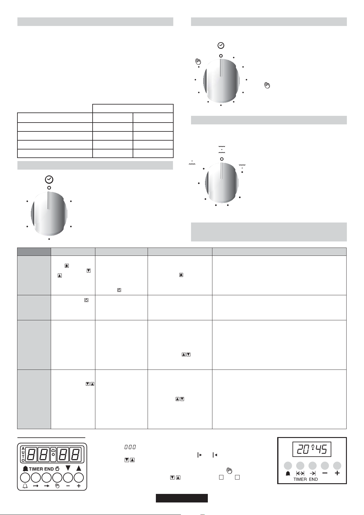
4.9. USING THE MINUTE TIMER
Figure 13
To set the cooking time, turn dial one
50
complete revolution and then position
10
the index to the required time. When the
time has lapsed, the signal will ring for a
few seconds.
4.10. USING THE END OF COOKING TIMER
Figure 14
90
80
70
10
50
60
This control enables to set the desired
cooking time (max. 90 min.) the oven will
automatically switch off at the end of the
set time.
The timer will count down from the set
20
time return to the “O” position and switch
off automatically.
30
For normal use of oven set the timer to
the position.
To set the oven ensure the timer is not on
40
the “O” position.
4.11. GAS OVEN
Figure 15
Min
150
180
210 240
The oven temperature and heater can be
selected by turning the oven adjustment
knob to the desired temperature level.
The oven thermostat range is: 140270°C.
Some cookers have flame safety device
on burners. If the flame goes out, the gas
supply is automatically cut off.
Max
40
FUNCTION
MINUTE
MINDER
MANUAL
FUNCTION
COOKING
TIME
END OF
COOKING
30
HOW TO ACTIVE
•Press and hold the
button
•Press the buttons
or to set the
equired time
•Release all the buttons
•Press the button
•Set the cooking
function with the oven
function selector
•Press and hold the
TIMER button
•Press the buttons
or to set the lenght
of cooking required
•Release all buttons
•Set the cooking
function with the oven
function selector
•Press and hold the
END button
•Press the buttons
to set the time at which
you wish the oven to
switch off
•Release the buttons
•Set the cooking
function with the oven
function selector
20
HOW TO SWITCH IT OFF
•When the set time as
elapsed an audible alarm
is activated (this alarm will
stop on its own, however
it can be stopped
immediately by pressing
the button)
•Turn the oven function
selector to position“O”
•When the time is elapsed
the oven will switch off
automatically. Should you
wish to stop cooking earlier
either turn the function
selector to 0, or set time to
0:00(TIMER and
buttons)
•At the time set, the oven
will switch off. To switch off
manually, turn the oven
function selector to position
“O”.
4.12. USE OF THE ELECTRONIC
PROGRAMMER
WHAT IT DOES WHAT IT IS FOR
•Sounds an alarm at the end of the
set time.
•To check how long is left to run
press the button
•Enables you to operate the oven.
•It allows to preset the cooking
time required for the recipe
chosen.
•To check how long is left to run
press the TIMER button.
•To alter/change the preset time
press TIMER and buttons
•Enables you to set the end of
cooking time
•To check the preset time press
the END button
•To modify the preset time press
buttons END+
•Allows to use the oven as alarm clock (could be activated either with
operating the oven or with out operating the oven)
•For cooking the desired recipes
•At the end of the cooking set time, the oven will switch off automatically
and an audible alarm will ring.
•This function is typically used with “cooking time” function. For example
if the dish has to be cooked for 45 minutes and needs to be ready by
12:30, simply select the required function, set the cooking time to 45
minutes and the end of cooking time to 12:30.
•Cooking will start automa-tically at 11:45 (12:30 minus 45 mins) and will
continue until the preset end of cooking time, when the oven will switch
itself off automatically
WARNING!
If the END of cooking is Selected without setting the length of cooking
time, the oven will start cooking Immediately and it will Stop at the END of
cooking time set.
Setting the correct time:
WARNING : the first operation to carry out after the oven has been installed or
following the interruption of power supply (this is recognizable the display pulsating
and showing ) is setting the correct time. This is achieved as follows
• Press and hold the TIMER and END buttons ( and )
• Set time with buttons
• Release all buttons
ATTENTION the oven only operates if set on manual function or preset time.
N.B.: on some models the symbols are replaced by + and - .
In the programming of a timer with 5 buttons, for manual function, press "TIMER"
and "END" buttons simultaneously
13 GB
Page 14
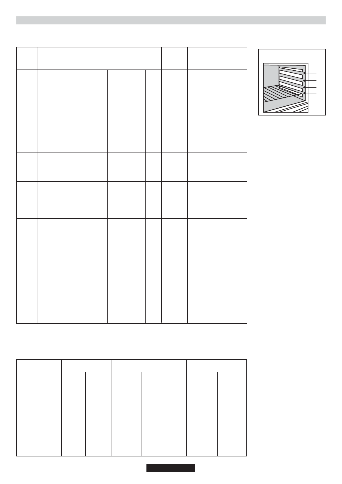
4.13. COOKING TABLES
Traditional and Hot Air Circulation Cooking Methods; Weights (Gr)
TYPE OF THE FOOD Traditional Cooking Method
Weight
(Gr)
1000
500
500
TYPE OF THE FOOD
CAKES AND DESSERTS
Dough with stirred egg
Dough
Small Cakes
Cheese Cake
Apple Pie
Strudel
Jam tart
Small cakes
Biscuits
Cream cakes
BREAD AND PIZZA
White Bread
Rye Bread
Sandwich
PASTRY
Macaroni
With vegetable
Small pastries
Lasagne
Traditional
Cooking
Method
Tempera-
Shelf
ture(°C)
Position
180
2
180
1
180
2
175
1
180
1
175
2
180
2
180
2
180
2
100
2
200
1
200
1
200
2
200
2
200
2
200
2
200
2
Hot Air
Circulation
Method
Shelf
Position
2(1and3)
2(1and3)
2(1and3)
2
2(1and3)
2(1and3)
2(1and3)
2(1and3)
2(1and3)
2(1and3)
2
2
2(1and3)
2(1and3)
2(1and3)
2(1and3)
2
Tempera-
ture(°C)
160
160
160
150
160
150
160
160
160
100
175
175
175
175
175
175
175
Cooking
times
(Minutes)
45 - 60
20 - 35
20 - 30
60 - 80
40 - 60
60 - 80
45 - 60
15 - 25
10 - 20
90 - 120
45 ~ 60
30 ~ 45
20 ~ 35
40 ~ 50
45 ~ 60
35 ~ 45
45 ~ 60
N O T E S
Shelf Pozitions
4
3
2
1
Figure 16
Inside the closed oven on
dishes 8 pieces on a tray
Under the grill
1000
1200
1000
1500
1200
1000
4000
1500
3000
1200
1000
800
MEATS
Roast beef
Roast pork
Roast veal
British style roast beef
Lamb
Chicken
Turkey
Duck
Goose
Rabbit
FISH
Whole fish
Fillet
200
2
200
2
200
2
220
2
200
2
200
2
200
2
175
2
175
2
200
2
200
200
2(1and3)
2(1and3)
2
2
175
2
175
2
175
2
200
2
175
2
175
2
175
2
160
2
160
2
175
2
175
175
50 ~ 70
100 ~ 130
90 ~ 120
50 ~ 70
110 ~ 130
60 ~ 80
210 ~ 240
120 ~ 150
150 ~ 200
60 ~ 80
40 ~ 60
30 ~ 40
Cook on grill
Cook on grill
Cook on grill
Cook on grill
Leg
Full size
Full size
Full size
Full size
In parts
2 Fishes
4 Fillets
NOTE :
1) Cooking times do not include pre heating. Preheating the oven for about 10 minutes is advisable especially for cakes, pizzas and breads.
2) Indicates tray positions for cooking several dishes simultaneously.
3) All cooking operations must be carried out with oven door closed.
COOKING TIMES
(Minutes)
UPPER
SECTION
10
12
10
30
12
13
12
8
12
8
2-3
LOWER
SECTION
8
8
6
20
10
10
-6
--
-1
FOOD TYPES
Beefsteak
Grilled cutlet
Sausage
Chicken parts
Mixed grill
Milky desserts
Tomato slices
Fish fillets
Scallops
Toast
Bread slices
QUANTITY COOKING ON GRILL
N. OF
PARTS
4
4
8
6
4
4
8
4
6
4
4
WEIGHT
800
600
500
800
700
400
500
400
---
--—
SHELF
POSITION
4
4
4
3
4
4
4
4
4
4
4
TEMPERATURE
(°C)
max
max
max
max
max
max
max
max
max
max
max
14 GB
Page 15

5. CLEANING AND MAINTENANCE
5.1. CATALYTIC SELF - CLEANING OVEN
Before all cleaning and maintenance :
•Cleaning and user maintenance shall not be made by children
without supervision
•Disconnect mains voltage.
•Shut off the gas valve for your own safety. If the oven is adjusted to
natural gas, shut off the natural gas valve.
•If the oven is hot, wait till it has cooled down.
•Clean enamelled surfaces with warm, soapy water or with suitable
brand products. On no account use abrasive powders that may
damage surfaces and ruin the appearance of the cooker.
It is very important to clean the oven each time it is used.
•Use detergents and abrasive metal pads for the stainless steel grills.
•The glass surfaces such as the top, the oven door and the warming
compartment door must be cleaned when they are cold.
•Damage caused by failure to respect this rule is not covered by the
guarantee.
•You can clean burners and burner caps with hot water and detergent.
Also the gas channels of the burners can be cleaned by a brush. Make
sure that burners are dry before replacing them in their seats. Check
correct positioning of the burner.
especially for cakes, pizzas and breads.
•Periodically clean the ignition electrodes of automatic ignition ovens.
This will prevent ignition problems. Check frequently that
the gas channels of burners are not blocked by food residues, etc.
•Wipe the top lid with a dry cloth in order to prevent harmful effects of
water, oil and steam generated by the cooked food.
•Do not use abrasive products, metal cleaning pads, sharp objects,
rough cloths, or chemical products and detergents that can
permanently damage the catalytic lining.
•It is a good idea to use deep roasting trays for fatty foods such as
joints of meat etc. and to put a tray underneath the grill to catch surplus
fat.
Cleaning of Oven Door
For thorough cleaning of the oven door, it is advisable to remove the
same, as shown in below.
Open the door completely, turn the two feet on the hinge arms 180º.
Close the door partly by a 30º. Remove the door by slightly lifting the it
at this position.
For replacing the door, follow the steps above in the reverse order.
0
180
•Special self-cleaning panels covered in a micro-porous coating are
available on some of our models. If they are fitted, the oven no longer
needs to be cleaned by hand.
•The lining must be porous for self-cleaning to be effective.
•Excessive splattering of fat may block the pores and therefore hinder
self-cleaning. This self-cleaning capacity may be restored by
switching on the empty oven to maximum for about 10-20 minutes.
•If the walls of the oven are so thickly coated in grease that the
catalytic lining is no longer effective, remove surplus grease with a soft
cloth or sponge soaked in hot water. All catalytic linings currently on
the market have a working life about 300 hours. They should therefore
be replaced after about 300 hours.
6. SERVICE CENTRE & TROUBLESHOOTING
•If the oven is not working, before calling the service centre we
recommended that :
•You should check that the oven is properly plugged into the power
supply.
Gas input is abnormal
•Check the following:
•Are the holes of the burner clogged?
•Is the pressure regulator working properly?
•If you are using a pipe, is there any gas in the pipe? Is the valve open?
•If you detect something abnormal with the gas valves, contact a
qualified electrician or an authorised service centre for assistance.
There is a smell of gas where the appliance is placed
•Please check the following:
•Has a gas valve been left open?
•Is the gas pipe in the correct position and in good condition?
If you suspect a gas leak, do not use a flame to check
The oven does not heat up
Are the oven control knobs at the correct position ?
The cooking time is too long
Has the correct temperature been selected ?
Smoke comes from the oven
It is advisable to clean the oven after each use. If fat which splashes
during the cooking of meat is not cleaned, it will cause an unpleasant
smell and smoke the next time you use the oven. (See the Cleaning
and Maintenance chapter)
The oven light does not come on
•The light might be faulty. To change the bulb, please see the relative
page.
•If you have checked the above and the oven still does not work
properly, contact the nearest authorized service for assistance
• Model and Production Number (PNC or ENR).
Figure 16
To Replace the inside light
•Switch off the mains power supply and unscrew bulb.
Replace with an identical bulb that can withstand very high
temperatures.
Figure 17
7. PROTECTION OF THE ENVIRONMENT
This appliance is marked according to the European
directive 2012/19/EU on Waste Electrical and
Electronic Equipment (WEEE). WEEE contains both
polluting substances (which can cause negative
consequences for the environment) and basic
components (which can be re-used). It is important to
have WEEE subjected to specific treatments, in order
to remove and dispose properly all pollutants, and
recover and recycle all materials.
Individuals can play an important role in ensuring that WEEE does not
become an environmental issue; it is essential to follow some basic
rules:
• WEEE shall not be treated as household waste.
• WEEE shall be handed over to the relevant collection points
managed by the municipality or by registered companies. In many
countries, for large WEEE, home collection could be present.
• When you buy a new appliance, the old one may be returned to the
retailer who has to collect it free of charge on a one-to-one basis, as
long as the equipment is of equivalent type and has the same
functions as the supplied equipment.
15 GB
Page 16

CONSEILS DE SÉCURITÉ
AVERTISSEMENT: L'appareil et les parties accessibles deviennent chauds pendant l'utilisation. Des
précautions doivent être prises pour éviter de toucher les éléments chauffants.
• Les enfants de moins de 8 ans doivent être tenus à l'écart à moins d'être surveillés continuellement.
• Cet appareil n'est pas destiné à être utilisé par des personnes (y compris les enfants) dont les capacités
physiques, sensorielles ou mentales sont réduites, ou ayant un manque d'expérience et de
connaissances, à moins qu'elles n'aient été formées à l'utilisation de l'appareil, par une personne
responsable de leur sécurité.
• Les enfants ne doivent jouer avec l'appareil.
• Le nettoyage et l'entretien par l'utilisateur ne doit pas être fait par des enfants sans surveillance.
ATTENTION: La cuisson sans surveillance sur une plaque de cuisson avec de la graisse ou d'huile peut
être dangereuse et peut entraîner un incendie.
• Ne jamais tenter d'éteindre un incendie avec de l'eau, mais éteindre l'appareil, puis couvrir la flamme
par exemple avec un couvercle ou une couverture anti-feu.
AVERTISSEMENT: Danger d'incendie: ne pas stocker des éléments sur les surfaces de cuisson.En
cours d'utilisation l'appareil devient chaud. Des précautions doivent être prises pour éviter de toucher les
éléments chauds à l'intérieur du four.
AVERTISSEMENT: Les parties accessibles peuvent devenir chaudes pendant l'utilisation. Les jeunes
enfants doivent être tenus à l'écart.
• Ne pas utiliser de nettoyants abrasifs ou de racloirs métalliques tranchants pour nettoyer la vitre de la
porte du four car ils peuvent rayer la surface, entrainant des risques d'explosion.
• L'intérieur du tiroir inférieur peut devenir chaud.Le liquide débordé doit être enlevé avant de
nettoyer.Pendant le fonctionnement de la pyrolyse, les surfaces peut devenir plus chaude que d'habitude
et les enfants doivent être tenus à l'écart.
• Le four doit être éteint avant d'enlever la protection et après le nettoyage, la protection doit être replacé
en respectant les instructions.
• Utiliser seulement la sonde de température recommandée pour ce four.
• Ne pas utiliser de nettoyants vapeur pour le nettoyage.
• Tout liquide doivent être enlevé du couvercle avant ouverture.
• Il est recommandé de laisser refroidir la table de cuisson avant de refermer le couvercle.
AVERTISSEMENT: Assurez-vous que l'appareil est éteint avant de remplacer la lampe afin d'éviter les
risques d'électrocution.
• Si le produit est placé sur un socle, des mesures doivent être prises pour eviter que le produit glisse de
son socle.
• Un moyen de déconnexion de l'alimentation secteur avec séparation de contact dans tous les pôles
assurant une déconnexion totale conformément aux conditions de surtension de catégorie III, doit être
intégré dans le câblage de fixation, selon les règles de câblage.
• Les instructions ndiquent le type de cordon à utiliser, en tenant compte de la température de la surface
arrière de l'appareil.
• Si le cordon d'alimentation est endommagé, il doit être remplacé par un cordon spécial disponible
auprès du fabricant ou de stations de dépannage agrées..
ATTENTION: Pour éviter tout danger dû à une réinitialisation accidentelle, cet appareil ne doit pas être
alimenté par un dispositif de commutation externe, comme une minuterie, ou connecté à un circuit qui est
régulièrement allumé et éteint par l'utilitaire.
• Cet appareil doit être installé en conformité avec la réglementation en vigueur et utilisé uniquement
dans un espace ventilé. Lisez les instructions avant d'installer ou utiliser cet appareil.
• Ces instructions ne sont valables que si le symbole du pays apparaît sur l'appareil. Si le symbole
n'apparaît pas sur l'appareil, il est nécessaire de se référer à la notice technique qui fournira les
instructions nécessaires concernant la modification de l'appareil selon les conditions d'utilisation du pays
• Avant l'installation, s'assurer que les conditions de distribution locale (la nature du gaz et la pression) et
le réglage de l'appareil sont compatibles.
• Les conditions de réglage de cet appareil sont indiqués sur l'étiquette (ou données de la plaque) .
• Cet appareil n'est pas relié à un dispositif d'évacuation des produits de combustion. Il doit être installé et
raccordé conformément aux règles d'installation en cours. Une attention particulière doit être accordée
aux exigences concernant la ventilation ".
• Les résultats de la table gaz dans la production de chaleur depend de l'humidité dans la pièce dans
laquelle elle est installé Veiller à ce que la cuisine soit bien ventilée. Laissez les ouvertures de ventilation
16 FR
Page 17

naturelle ouvertes ou installez un dispositif de ventilation mécanique (hotte aspirante mécanique). Une
utilisation intensive prolongée de l'appareil peut faire appel à l'utilsation d'une ventilation
supplémentaire, par exemple d'ouverture d'une fenêtre, ou plus efficace de ventilation mécanique, par
exemple en augmentant le niveau de la ventilation mécanique présent.
ATTENTION: Les parties accessibles peuvent être chaudes lorsque le barbecue est en cours
d'utilisation. les jeunes enfants doivent être tenus à l'écart.
AVERTISSEMENT : Installer un dispositif de stabilisation pour éviter un éventuel renversement de
l'appareil. Consulter les consignes figurant à la page 02 du présent manuel.
1.RECOMMANDATIONS
Nous vous remercions d'avoir choisi l'un de nos produits.
•Afin de tirer le meilleur parti de votre appareil, nous vous recommandons :
de LIRE ATTENTIVEMENT CETTE NOTICE et de la conserver dans un
endroit sûr pour toute consultation ultérieure. Elle contient des instructions
importantes concernant l'installation et l'utilisation de votre cuisinière.
•de remettre cette notice avec l'appareil en cas de sa revente.
•Lorsque la cuisinière est en fonctionnement, la porte, les parties
accessibles ainsi que tous les éléments chauffants sont brûlants ; nous
recommandons donc de ne pas toucher et d'éloigner les jeunes enfants
•Lors de la première mise en service de l'appareil, une odeur dé brûlé est
susceptible d'apparaitre cette fumée est inoffensive. Nous vous
recommandons alors de faire fonctionner l'appareil vide pendant deux
heures.
1.1. SYMBOLES UTILISES DANS LA NOTICE
Pour faciliter votre compréhension, les symboles suivants sont
utilisés dans cette notice :
Information importante de sécurité
Information pour la protection de l'environnement
Appareil conforme aux directives CEE de l'Union
Européenne
Attention, possibilité de basculement.
Restrictions anti-basculement.
1.2. DECLARATION DE CONFORMITE
Cet équipement, dans les parties destinées à entrer en contact avec les
aliments, est conforme aux normes fixées par les directives CEE 89/109.
•Des éclaboussures peuvent être projetées lors de la cuisson
d'aliments ou lorsque le plat contient trop d'eau ou de gras. Dans ce
cas, immédiatement nettoyer les résidus après la cuisson en vue
d'éviter le développement d'odeurs ou de feu.
• Eteindre le feu avant de retirer les plats ou casseroles.
•ATTENTION ! De la chaleur et de l'humidité peuvent se former lors
de la combustion de combustibles gazeux. Prêter une attention
particulière à la bonne aération de la pièce dans laquelle est placée
l'appareil : si l'aération naturelle est inexistante ou insuffisante, il
convient d'installer une grille d'aération. En cas de doute, consulter un
centre d'assistance technique GIAS.
•L'utilisation d'un appareil électroménager requiert le respect de
quelques règles de base :
*Il est en général déconseillé d'utiliser un adaptateur ou une prise
multiple.
*Ne pas tirer sur le câble d'alimentation pour éteindre l'appareil.
*Ne pas toucher le four avec les mains mouillées.
*Remplacer immédiatement le câble d'alimentation s'il est
endommagé en suivant les instructions suivantes :
*Le remplacement doit être effectué par un technicien qualifié. Pour la
réparation, se rapprocher exclusivement d'un centre d'assistance
agréé et assurez-vous qu'ils utilisent des pièces de rechange
d'origine.
*Si nécessaire, enlever le câble d'alimentation et le remplacer avec un
autre du type : H05RRF, H05VVF et H05V2V2-F. Ce câble a la
capacité suffisante pour supporter la tension électrique requise par le
produit.
•Contrôler régulièrement le flexible de gaz.
•Le flexible de gaz doit être tenu à l'écart des parties chaudes du four
et ne doit pas être en contact avec ce dernier. Il est possible de
positionner le connecteur du gaz à droite ou à gauche du four. Après
une telle modification, vérifier qu'il n'y a pas de fuite à l'aide d'un petit
peu d'eau savonneuse.
•Ne pas laisser l'appareil sans surveillance avant qu'il ne soit
complètement refroidit.
L'appareil est conforme aux directives européennes remplacée par
2009/142/EC ses modifications ultérieures.
En utilisant le symbol sur ce produit, nous déclarons sur notre
propre responsabilité que ce produit est conforme à toutes les normes
Européennes relatives à la sécurité, la santé et à l’environnement.
1.3. CONSIGNES DE SECURITE
•Cette cuisinière est exclusivement destinée à un usage domestique dans
le cadre de la cuisson d'aliments. Si l'appareil est utilisé à d'autres fins, tel
que comme un chauffage, ou mal utilisé, cela peut être dangereux et le
constructeur ne peut être tenu responsable des dommages
éventuellement causés.
•Vous devez respecter les règles de base relatives aux appareils
électriques. S'il se casse ou fonctionne anormalement, débrancher-le, ne
le touchez pas et prenez contact avec votre réparateur agréé.
•Cet appareil ne doit pas être utilisé par des personnes (y compris les
enfants) à capacité réduite, à moins qu'elles soient sous la surveillance
d'une personne responsable de leur sécurité.
•Le tiroir du four est destiné au stockage de plats vides ou au maintien au
chaud des plats.
•Ne pas mettre d'objets explosifs, inflammables ou de matériel de
nettoyage dans le four comme du nylon, du papier ou des vêtements, etc.
dans le tiroir du four.
•N'utilisez que des plats résistants et destinés à cet effet pour la cuisson de
vos aliments. Ne pas utiliser de récipients inflammables.
•La cuisinière possède des caractéristiques techniques définies et en
aucun cas des modifications ne doivent être apportées sur cet appareil.
•Une attention particulière doit être portée à l'appareil lors de la cuisson :
restez à proximité.
•La cuisinière est lourde. Faites attention lorsque vous la déplacez.
•L'émission d'air chaud est normale durant la cuisson. Ne pas
ventilations de l'appareil.
obstruer les
Le fabricant ne peut garantir la sécurité de la cuisinière
si les règles précédemment citées ne sont pas respectées.
1.4. CONSEILS UTILES
La présence d'un couvercle supérieur permet d'éviter la présence de
poussière sur la table de cuisson lorsqu'il n'est pas utilisé et des
éclaboussures d'huile sur les murs lors de la cuisson.
•Ne pas utiliser le couvercle à d'autres fins.
•ATTENTION ! (pour les modèles ayant un couvercle en verre) Le
couvercle peut s'abimer s'il est exposé à une température trop élevée.
Toujours s'assurer que les feux soient éteints avant de refermer le
couvercle.
•Ne pas utiliser de plats ou de casseroles déformés ou instables
•Nettoyer les grilles et la lèchefrite avant utilisation.
•Ne pas vaporiser de détergent sur les plats et la grille, ni sur le
thermostat.
•S'assurer que les plats du four soient correctement positionnés.
•Allumer les plaques avant de placer les plats de cuisson pour un
allumage plus rapide.
•Vérifier que la taille des flammes soit adaptée aux plats de cuisson.
•Ne pas tapisser les parois du four avec des feuilles en aluminium ou
des protections jetables du commerce. La feuille d'aluminium ou toute
autre protection, en contact direct avec l'émail chauffé, risque de
fondre et de détériorer l'émail du moufle.
17 FR
Page 18

2. INSTALLATION
La mise en place fonctionnelle des appareils ménagers dans leur
environnement est une opération délicate qui, si elle n'est pas correctement
effectuée, peut avoir de graves conséquences sur la sécurité des
consommateurs. Dans ces conditions, il est impératif de confier cette tâche à un
professionnel qui la réalisera conformément aux normes techniques en vigueur.
Si malgré cette recommandation, le consommateur réalisait lui-même
l'installation, le constructeur déclinerait toute responsabilité en cas de défaillance
technique du produit entraînant ou non des dommages aux biens et/ou aux
personnes.
ATTENTION ! Il convient de prêter la plus grande attention au positionnement
de l'appareil. Ce dernier ne peut être installé que dans une pièce où la ventilation
est assurée en continu. L'appareil doit toujours être débranché avant toute
intervention.
"Les résultats de la table gaz dans la production de chaleur depend de l'humidité
dans la pièce dans laquelle elle est installé Veiller à ce que la cuisine soit bien
ventilée. Laissez les ouvertures de ventilation naturelle ouvertes ou installez un
dispositif de ventilation mécanique (hotte aspirante mécanique). Une utilisation
intensive prolongée de l'appareil peut faire appel à l'utilsation d'une ventilation
supplémentaire, par exemple d'ouverture d'une fenêtre, ou plus efficace de
ventilation mécanique, par exemple en augmentant le niveau de la ventilation
mécanique présent.
•Contrôler le branchement du gaz (type et pression du gaz) avant l'installation de
l'appareil et s'assurer que l'appareil soit réglé en adéquation.
•Cet appareil ne doit pas être relié à un autre appareil fonctionnant avec un autre
combustible.
•L'appareil ne doit pas être installé à proximité d'un matériel inflammable.
•Si le produit est placé sur un socle, des mesures doivent être prises pour eviter
que le produit glisse de son socle.
2.1. ENVIRONNEMENT DANS LEQUEL
L'APPAREIL DOIT ÊTRE INSTALLE
•L'appareil doit être positionné sur un emplacement stable
•Pour le bon fonctionnement, le local dans lequel l'appareil est installé doit être
ventilé naturellement de telle manière à ce que les gaz brûlés soient évacués.
•Le flux d'air doit pouvoir pénétrer dans les prises d'air grillagées présentes sur
les parois extérieures.
•Les grilles doivent être positionnées de telle manière à ce que la
ventilation ne puisse être obstruée d'aucun des deux côtés et de
préférence près du sol. Elles ne doivent pas être mises sur des tuyaux
d'évacuation de gaz brûlés ou de fumées.
•Toutefois, s'il est impossible de mettre des grilles d'aération dans la pièce
dans laquelle l'appareil est installé, la ventilation peut être faite avec une
pièce attenante s'il ne s'agit pas d'une chambre à coucher ou d'une pièce
où les courants d'air pourraient représenter un risque.
2.2. POSITIONNEMENT
200 mm 200 mm
750 mm
400 mm
Cet appareil est "classe 2.1".
L'appareil a été conçu en partant
du principe selon lequel les plans
de travail adjacents ne seront pas
supérieurs à la surface du plan de
travail.
2.3. REGLAGE DES PIEDS
La cuisinière est dotée de pieds réglables aux 4 angles du châssis.
Les pieds doivent être réglés l'un après l'autre à l'aide d'une clef pour que
l'appareil soit positionné de telle manière à ce qu'il soit parfaitement stable
et que les plats posés sur les plaques soient parfaitement équilibrés.
•Sur les modèles dotés d'un dispositif de sécurité des flammes, afin
d'assurer le passage de l'air, la partie transversale de la grille d'air doit
mesurer 100 cm . Sur les modèles privés de dispositif de sécurité, elle doit
être de 200 cm (il est possible de mettre une ou plusieurs grilles).
2
2
Emission de gaz combustibles
•Les gaz brûlés de la cuisinière doivent être directement évacués à
l'extérieur ou par l'intermédiaire d'une hotte connectée à une évacuation
(figure 1).
•S'il est impossible d'installer une hotte, il convient d'installer une
ventilation électrique sur le mur ou la fenêtre tournée vers l'extérieur
(figure 2)
•La ventilation doit assurer le renouvellement de l'air de la pièce de 3 à 5
fois par heure.
Roues ajustables et roues
AA1
A2
4
3
2
1
CB
•La cuisinière est dotée de 2 pieds et de 2 roulettes réglables aux angles
du châssis.
•La hauteur maximale du four est de 868 mm en fixant les pieds réglables à
l’avant et les roues à l’arrière au 4ème trou.
•Les pieds doivent être réglés l'un après l'autre à l'aide d'une clef pour que
l'appareil soit positionné de telle manière à ce qu'il soit parfaitement stable
et que les plats posés sur les plaques soient parfaitement équilibrés.
•Les roues arrières doivent être fixées au 2ème trou (photo A1) pour
atteindre la taille standard de 850 mm.
Figure 1 Figure 2
Roues ajustables
18 FR
Page 19

2.4. RACCORDEMENT ELECTRIQUE
Les cuisinières sont fournies avec ou sans câble d'alimentation. Le
raccordement est prévu exclusivement sous des tensions de 220-
240V entre phases ou entre phase et neutre.
Le raccordement du câble doit être fait par un centre d'assistance
agréé qui devra se tenir aux instructions suivantes.
L'installation recevant l'appareil doit être conforme aux normes en
vigueur dans le pays d'installation (FRANCE : Norme NFC 15100). La
Société décline toute responsabilité en cas de non-respect de cette
disposition.
•Le technicien doit, avant de procéder au raccordement, vérifier la
tension d'alimentation indiquée au compteur, le réglage du
disjoncteur, le calibre du fusible et la continuité de la terre de
l'installation.
•Le raccordement au réseau doit être effectué par une prise de
courant avec prise de terre, ou par l'intermédiaire d'un dispositif à
coupure omnipolaire.
•Si l'appareil comporte une prise de courant, il doit être installé de telle
façon que la prise de courant soit accessible.
•Le fil de protection vert/jaune doit être relié aux bornes de terre, de
l'appareil d'une part et de l'installation d'autre part.
•Le câble d'alimentation doit être disposé de telle manière à ce qu'il ne
soit pas exposé à une température supérieure à 50°.
•Contrôler la bonne installation en les allumant pendant 3 minutes.
•Si l'appareil n'est pas muni d'un cordon d'alimentation et d'une prise,
ou d'un autre moyen assurant que l'appareil puisse être déconnecté
du réseau d'alimentation dans le cas d'un surtension répondant aux
conditions de catégorie III, il est nécessaire d'intégrer un système de
disjoncteur dans le câblage, conformément aux règles établies en la
matière.
2.6. CUISINIERE LIVREE SANS CORDON
D'ALIMENTATION
Type de boitiers de raccordement
1- branchement monophasé 2- branchement triphasé
Attention: Une inversion de la phase et du neutre sur les
cuisinières peut entraîner un dysfonctionnement des produits.
2.5. CUISINIERE LIVREE AVEC CORDON
D'ALIMENTATION
•Il est uniquement prévu un câble de raccordement pour les mises
sous des tensions à 220-240V entre phase et neutre.
Neutre
Phase (marron)
Terre (jaune et vert)
•L'éventuel remplacement du cordon d'approvisionnement doit être
effectué par le service après-vente ou par le convenus ingénieur, avec
un cordon dont les caractéristiques doivent être semblables à
l'original.
Tableau de correspondance des câbles d'alimentation
Modèle (kW)
2.3 kW
3.5 kW
4.0 kW
Puissance (V)
220 - 240 V
220 - 240 V
220 - 240 V
nominale (A)
(bleu)
Tension
9.1 A
15.9 A
18.2 A
Câble
d'alimentation
3 x 1.0 mm
3 x 1.5 mm
3 x 2.5 mm
2
2
2
Monophase
220-240 V~
3 G 4 mm
H05VV-F
H05RR-F
L1 : Phase
Shunter 1-2
Shunter 2-3
N : Shunter
Biphase
380-415V2N~
Triphase
380-415V3N~
Câble - Section
2
4 G 1.5 mm
2
5 G 1.5 mm
2
Câble Type
H05VV-F
H05RR-F
1 Phase
2 Phase
5 Neutre
Shunter 4-5
H05VV-F
H05RR-F
1 Phase
2 Phase
3 Phase
5 Shunter
19 FR
Neutre 4-5
PE : Terre
PE Terre
Neutre 4-5
PE : Terre
Page 20

2.7. RACCORDEMENT GAZ
Avant installation, le technicien doit :
•Vérifier la compatibilité entre l'appareil et l'installation gaz. La
cuisinière est réglée en usine pour le fonctionnement au gaz dont la
nature est indiquée sur l'emballage et rappelée sur l'étiquette apposée
sur l'appareil. S'assurer que le gaz que vous utilisez coïncide avec celui
de la cuisinière. Effectuer, si nécessaire, le changement de gaz en
adaptant les brûleurs avec la mise en place des injecteurs appropriés
qui assurent le débit nominal en suivant les instructions du chapitre «
modification pour type de gaz différent»
•S'assurer que la pression du gaz est celle donnée dans le tableau ci-
après afin d'atteindre une efficacité optimale et de réduire la
consommation. En cas d'utilisation d'un gaz dont la pression est
différente, il convient d'utiliser un régulateur sur la prise du gaz.
L'utilisation d'un régulateur de gaz conforme aux standards GPL est
admise.
•Le raccordement gaz doit être effectué conformément aux règlements
en vigueur dans le pays d'installation. (Voir les 3 dernières pages du
mode d’emploi) Dans tous les cas, prévoir sur la canalisation d'arrivée
du gaz un robinet d'arrêt, un détendeur ou un détendeur déclencheur
pour le gaz propane. N'utiliser que des robinets, détendeurs, abouts et
tubes souples, détenteurs de la marque officielle du pays d'installation.
Raccordement par tuyau rigide ou flexible à embout mécanique
•Raccorder directement au robinet de gaz à l'aide d'un flexible en inox
en veillant à respecter les précautions de sécurité. Dans ce cas, il n'y
aura plus besoin de déplacer la cuisinière. Le connecteur d'entrée du
gaz de l'appareil est GC ½. Nous conseillons ce type de raccordement.
Raccordement par tuyau souple caoutchouc
•Nous déconseillons ce type de raccordement (à réserver seulement
aux installations anciennes n'offrant pas d'autres possibilités).
•Ce type de raccordement ne doit être fait que sous réserve que le tube
souple soit visitable sur toute sa longueur, que la longueur n'excède pas
1,5 mètre et qu'il soit équipé de colliers de serrage.
•Le raccordement peut être effectué comme suit :
-Puisque le flexible sera placé derrière le four, il ne doit pas être exposé
à une température supérieure à 30°C.
-Il ne doit pas être exposé à la chaleur
-Il ne doit pas être tordu, écrasé ni tendu.
-Il doit être protégé des objets tranchants et pointus
-Il doit être accessible pour permettre un contrôle régulier.
-Le flexible doit être contrôlé comme suit pour prévenir des dommages
de l'usure : vérifier qu'il ne soit pas cassé, entaillé ou brulé sur toute la
longueur et sur les extrémités ; il doit conserver sa flexibilité et ne pas
durcir ; il ne doit pas y avoir de traces de rouille sur les côtés.
-Dans tous les cas, il convient de le remplacer dans les 5 ans.
2.8. MODIFICATION POUR TYPE DE GAZ
DIFFERENT
Les réglages ci-dessous doivent être réalisés par un technicien qualifié.
Il convient de suivre les instructions suivantes pour convertir l'appareil en
remplaçant les réglages établis en usine pour un autre type de gaz.
Les cuisinières sont réglées pour le gaz naturel dont l'embout de
connexion est cylindrique (1).
Pour ce type de raccordement, un adaptateur (2)
peut-être ajouté à l'embout cylindrique.
Pour un raccordement au GPL (Butane/Propane),
un autre adaptateur (3) est prévu pour être visé à
l'embout cylindrique.
Remplacement des injecteurs des brûleurs
•Enlever les grilles.
•Enlever les chapeaux et corps du brûleur
•Au moyen d'une clé à pipe adaptée (7mm),
dévisser l'injecteur et le remplacer par un injecteur
correspondant au type de gaz distribué (comme
décrit dans le tableau des correspondances voir
les 3 dernières pages de cette notice)
•Remettre chaque élément à sa place après avoir
changé les brûleurs.
Réglage du ralenti
Réglage du ralenti pour les cuisinières sans dispositifs de sécurité
ou avec dispositifs de sécurité et allumage manuel.
•Tourner la manette de contrôle du brûleur en position « ralenti ».
L'enlever.
•Si le changement pour passer du gaz naturel au Propane/Butane est
nécessaire, dévisser la vis bipasse d'un tour (dans le sens des aiguilles
d'une montre)
•Si le changement pour passer du Propane/Butane au gaz naturel est
nécessaire, tourner la vis bipasse dans le sens inverse des aiguilles d'une
montre avec un tournevis jusqu'à l'obtention d'une petite flamme inférieure
à ¼.
•Après le réglage, remettre la manette.
•Contrôler le bon réglage en tournant très rapidement de la petite à la
grande flamme. Si la flamme ne s'éteint pas, le réglage est correct.
•S'il y a un dispositif de sécurité, le réglage du ralenti de la flamme peut être
fait en réglant la vis se trouvant sur le robinet du brûleur. Dans le cas d'un
allumage une main, le réglage peut être fait en enlevant la table, le
couvercle et le bandeau de contrôle.
1
3
Sans dispositif
de sécurité
2
BON
FLEXIBLE DE GAZ
CÂBLE ÉLECTRIQUE
MAUVAIS
FLEXIBLE DE GAZ
CÂBLE ÉLECTRIQUE
Après l'installation, vérifier qu'il n'y ait pas d'éventuelle
déperdition dans le raccordement à l'aide d'eau savonneuse.
Ne jamais utiliser de flamme pour contrôler une éventuelle perte
de gaz.
•Pour le réglage au ralenti de la vanne thermostatique, la table, le
couvercle et le bandeau doivent être retirés.
Vis bipasse sur le brûleur
Dispositif de
sécurité
Four Gaz
•Retirer le couvercle de protection situé à l'arrière (Figure 3)
•Retirez l'adaptateur de l'injecteur. (Figure 4)
•Retirez les injecteurs à l'aide d'une clé de 7 mm, puis visser sur le bon
injecteur sélectionné selon le gaz de la table (cf 3 dernières pages de
ce manuel) (Figure 5).
•Suivez les étapes ci-dessus dans l'ordre inverse après avoir terminé
l'installation du nouvel injecteur.
•Le brûleur est de 4,5 ± 0.3mm pour le gaz naturel et le GPL (Figure 6)
Figure3 Figure4
20 FR
Page 21

4.5 + 0.3
Figure5 Figure6
2.9. DIMENSIONS DE L'APPAREIL
60 x 60
850
598-600
Hauteur (mm)
Largeur (mm)
50 x 60
863
510
Table de cuisson
1-
Tableau de bord avec commandes
2-
Tiroir du four
3-
Porte du four
4-
Couvercle en verre ou en métal
5-
Brûleur auxiliaire
6-
Brûleur rapide
7-
Plaque électrique
8-
Plaque électrique
9-
Grille de droite
10-
Manettes de contrôle
11-
des brûleurs
Manette de contrôle des
12-
plaques électriques
Manette de thermostat du four
13-
Bouton d'allumage ou de
14-
mise en marche de la
ventilation
Voyant de contrôle
15-
P
Profondeur (mm)
600
600
H
L
2.10. ASPECT GENERAL ET DEFINITION DE
L'APPAREIL
Cette notice est commune à plusieurs modèles. Il est possible que
certaines caractéristiques décrites ici n'existent pas sur certains
modèles.
Table de cuisson
1-
Tableau de bord avec commandes
2-
Tiroir du four
3-
Porte du four
4-
Couvercle en verre ou en métal
5-
Brûleur auxiliaire
6-
Brûleur rapide (semi-rapide)
7-
Brûleur ultra-rapide (rapide)
8-
Brûleur semi-rapide
9-
Grille de gauche
10-
Grille de droite
11-
Manettes de contrôle des
12-
brûleurs
Manette de thermostat du
13-
four
Bouton d'allumage ou de mise
14-
en marche de la ventilation
Interrupteur éclairage
15-
Manette du timer
16-
Roulettes
17-
Boulon de pied
18-
14
15
13
12
16
10
9
11
17
18
Table de cuisson
1-
Tableau de bord avec commandes
2-
Tiroir du four
3-
Porte du four
4-
Couvercle en verre ou
5-
en métal
Plaques électriques
6-
Plaques électriques
7-
Manette de contrôle
8-
des plaques
Manette de
9-
thermostat du four
Voyant de contrôle
10-
1-
Table de cuisson
2-
Tableau de bord avec commandes
3-
Tiroir du four
4-
Porte du four
5-
Couvercle en verre ou en métal
6-
Brûleur auxiliaire
7-
Brûleur rapide (semi-rapide)
8-
Brûleur ultra-rapide (rapide)
9-
Plaque électrique
10-
Grille de gauche
11-
Grille de droite
12-
Manettes de contrôle des
brûleurs
13-
Manette de contrôle de la
plaque électrique
14-
Manette de thermostat du four
15-
Bouton d'allumage ou de mise
en marche de la ventilation
16-
Voyant de contrôle
17-
Roulettes
18-
Boulon de pied
RETRAIT ET NETTOYAGEDES GRILLES
1-Retirez lesgrillesen les tirant vers l’intérieur du four (voir schéma)
2- Mettez les grilles directement au lave-vaisselle ou lavez-les
simplement avec une éponge humide et veillez à bien les essuyer.
3-Une fois les grilles nettoyées, reclipser-les dans le four ( voir
schéma)
5
4
3
2
1
17
18
21 FR
Page 22

3. UTILISATION DES BRÛLEURS
3.1. UTILISATION DES BRÛLEURS
DE LA TABLE DE CUISSON
Les manettes qui contrôlent les brûleurs sont placées sur le panneau de
commandes.
Figure 7
Position éteinte
Lorsque la manette est tournée sur le symbole « O », le brûleur est
éteint, la valve du gaz est fermée et la flamme s'éteint.
Débit de gaz maximum
Appuyer sur la manette du brûleur et la tourner à gauche vers la
flamme la plus grande. Dans cette position, la flamme est au
maximum et la valve de diffusion du gaz est complètement ouverte.
Débit de gaz minimum
L'intensité de la flamme peut être diminuée en tournant la manette
soit positionnée sur le symbole indiquant la petite flamme. La valve
sera partiellement ouverte et le brûleur sera au minimum.
A - Chapeau de brûleur
B - Tête de brûleur
A
B
C
F
D
E
C - Bougie
D - Injecteur
E - Corps du brûleur
F - Dispositif de sécurité
Après l'allumage régler la flamme à l'intensité voulue.
Allumage manuel (en cas de coupure de courant)
Approcher une flamme (allumette ou briquet) du brûleur.
ATTENTION ! Toujours attendre une minute entre deux tentatives
d'allumage.
Appuyer sur la manette et la tourner jusqu'au symbole de la grande
flamme. Si le brûleur ne s'allume pas à la première tentative,
réessayer en appuyant un peu plus longtemps sur la manette. Quand
le brûleur est allumé, régler la flamme sur la bonne intensité.
Si le brûleur ne s'allume pas après plusieurs tentatives, vérifier que le
chapeau et la tête du brûleur soient bien positionnés.
Pour couper le gaz, tourner la manette dans le sens des aiguilles
d'une montre sur la position “ O ”. Si le brûleur s'éteint
accidentellement, attendre au moins une minute avant de le rallumer.
Certaines cuisinières sont dotées de dispositifs de sécurité de flamme
(« F » sur le schéma joint). En cas de coupure de la flamme, l'arrivée
de gaz est automatiquement interrompue.
Diamètres minimum et maximum de base des récipients de
cuisson :
Brûleur
Brûleur auxiliaire
Brûleur semi-rapide
Brûleur rapide
Ultra rapide brûleur
•La partie externe de la flamme est plus chaude que la partie
intérieure. Le sommet de la flamme doit toucher le fond du récipient.
Les flammes qui s'étendent en dehors du récipient peuvent causer
une consommation inutile de gaz.
•Les brûleurs de gaz, contrairement aux plaques électriques,
n'exigent pas de récipients avec le fond plat, la flamme qui touche le
fonds du récipient conduisant complètement la chaleur.
•Bien qu'ils n'y ait pas de préconisation particulière de récipient pour
les brûleurs à gaz, les récipients constitués de matières légères
conduisent plus rapidement la chaleur que ceux plus lourds.
•Certaines parties des aliments peuvent être chaudes alors que
d'autres sont encore froides à cause de la distribution non uniforme de
la chaleur sous le récipient. Ainsi, lors de l'utilisation de récipients
légers (au fond fin), il est nécessaire de mélanger continuellement la
nourriture pendant la cuisson. La chaleur est distribuée de manière
plus efficace et uniforme dans les récipients à fonds plus épais.
•L'usage de récipients de cuisson trop petit est déconseillé. Les
récipients profonds et dont le fond n'est pas concave ni convexe sont
plus adéquats pour une cuisine rapide et efficace que des récipients
plus petits et profonds.
•Il est impossible de diminuer le temps de cuisson en utilisant un petit
récipient sur un grand brûleur. Il en résulte uniquement un gaspillage
de gaz. Cependant, un récipient doté d'un couvercle permet
d'économiser de l'énergie.
Diamètre mini. (mm)
Ø 240 mm
Ø 180 mm
Ø 120 mm
Ø 240 mm
Diamètre maxi. (mm)
Ø 280 mm
Ø 240 mm
Ø 180 mm
Ø 280 mm
Figure 8
Allumage des brûleurs
Brûleurs à gaz de la table de cuisson
Le brûleur doit être allumé avant de poser une casserole.
Sur les modèles avec allumage automatique il est d'abord nécessaire
d'appuyer sur le bouton portant le symbole d'une étincelle.
Appuyer sur la manette de contrôle du brûleur que vous voulez allumer et
tournez la à gauche jusqu'au symbole de la grande flamme. Appuyer sur le
bouton d'allumage Sur les modèles avec un allumage grâce aux
manettes, appuyer sur la manette qui contrôle le brûleur concerné et la
tourner jusqu'au symbole de l'étincelle : l'allumage s'activera
automatiquement. Toutes les électrodes seront activées
automatiquement, allumant ainsi l'allumage sur lequel le gaz est ouvert
(celui relatif à la manette qui a été manipulée).
Brûleurs à gaz du four
Il ne faut pas appuyer sur le bouton pendant plus de 15 secondes. Après
15 secondes, si le brûleur ne s'est pas allumé, relâcher le bouton et ouvrir
la porte et/ ou attendre au moins une minute avant de réessayer d'allumer.
Sur les autres modèles, le gaz est allumé par l'intermédiaire de la manette
de contrôle.
S'assurer que le gaz soit effectivement fonctionnel. S'il
n'y a pas de flamme, recommencer la même procédure.
3.2.UTILISATION DES PLAQUES ELECTRIQUES
DE LA TABLE DE CUISSON
Tourner la manette sur la position indiquant la position désirée pour la
plaque concernée. Le témoin lumineux de la plaque s'illumine et la
plaque commence à chauffer.
A la fin de la cuisson, tourner la manette sur la position « O ». Ne pas
laisser la plaque allumée sans plat dessus. Il est très important
d'utiliser un récipient au diamètre adapté à celui de la plaque. Le
diamètre maximum de la base du récipient est de 14 cm et le fond doit
être plat. Lors de la première utilisation, laisser la plaque chauffer
pendant 5 minutes avant de poser un récipient dessus. Cela permet
au revêtement résistant à la chaleur de la plaque de durcir grâce au
réchauffement. Pour le nettoyage de la plaque, utiliser un chiffon
humide et un détergent. Ne pas enlever les résidus de viande des
plaques à l'aide d'un couteau ou d'un quelconque objet dur et
tranchant.
Après l'avoir nettoyée, allumer la plaque quelques instants pour la
faire sécher. Toutefois, elle ne doit pas rester allumée sans récipient
dessus pendant plus de quelques instants.
22 FR
Page 23

Hilight
6
5
4
Figure 9 Figure 10
Position
0
1
2
3
4
5
6
Puissance
0
100 W
180 W
250 W
500 W
750 W
1000 W
(Watt)
Puissance
(Watt)
0
135 W
220 W
300 W
850 W
1150 W
1500 W
Puissance
(Watt)
0
175 W
220 W
300 W
850 W
1150 W
2000 W
1
2
3
Description
Eteint
Maintien en température
Cuisson à basse température
Cuisson à basse température
Cuisson, friture, ébullition
Cuisson, friture, ébullition
Cuisson, friture, ébullition
Plats de cuisson adaptés
Les récipients plus grands ont des surfaces de chauffe plus importantes,
ce qui permet de cuire les aliments plus rapidement que dans un récipient
plus petit.
Utiliser toujours des récipients de dimension proportionnelle à la quantité
de nourriture à cuire. Pour éviter les débordements, éviter les récipients
trop petits, surtout pour les aliments contenant beaucoup d'eau. Si un trop
grand récipient est utilisé pour les aliments à cuisine rapide, la sauce et le
jus colleront au récipient et resteront collés après la cuisson. Pour la
cuisson de mets sucrés, les récipients et casseroles fermés sont
recommandés. Sucre et jus contenus dans un récipient ouvert peuvent
éclabousser et coller au plan de cuisson et ainsi être difficiles à retirer.
OUI NON NON NON NON
4. UTILISATION
4.1. UTILISATION DU FOUR GRIL
GRIL ÉLECTRIQUE : L'utiliser UNIQUEMENT
avec la porte du four fermée
GRIL À GAZ : Vous pouvez l'utiliser la porte
ouverte, AVEC le protecteur de panneau
inséré sous le panneau de commande, tel que
indiqué sur l'image.
•Le gril permet de faire dorer les aliments
rapidement. Le gril est réglable sur plusieurs
positions selon la taille du plat contenant les
aliments. Presque tous les types d'aliments
peuvent être cuits avec le gril, exceptés les
pièces très fines et les petits morceaux de
•Le gril permet de faire dorer les aliments rapidement. Le gril est réglable sur plusieurs
positions selon la taille du plat contenant les aliments. Presque tous les types d'aliments
peuvent être cuits avec le gril, exceptés les pièces très fines et les petits morceaux de
viande.
•Viandes et poissons destinés pour être grillés doivent auparavant être badigeonnés
d'huile.
•Lorsque vous utiliséz le gril, positionner la lèchefrite en-dessous de manière à récupérer
le gras. Verser un peu d'eau dans le plat de manière à éviter la formation d'odeurs
désagréables et l'inflammation des graisses.
•Le gril est habituellement utilisé pour cuire des morceaux de viande, par exemple des
biftecks pas trop épais, des pièces de gibier, du poisson et certains légumes (comme les
courgettes, les aubergines ou les tomates) ou les brochettes de viande ou de poisson.
Badigeonner légèrement le poisson d'huile avant de le mettre sous le gril. Saler la viande
après la cuisson; saler le poisson à l'intérieur avant la cuisson.
•La distance du gril dépend de l'épaisseur de la viande ou du poisson. Si la distance est
correctement choisie, la surface externe ne sera pas brûlée alors que l'intérieur sera
parfaitement cuit.
•Pour prévenir la formation de fumée et de mauvaises odeurs dues aux graisses et
sauces, verser un ou deux verres d'eau sur la lèchefrite.
Il est aussi possible d'utiliser le gril pour griller le pain et les toasts et pour cuisiner
certains types de fruits (banane, pamplemousse, ananas, pommes…). Les fruits ne
doivent pas être en contact avec les éléments chauffants du four.
Ne pas tapisser les parois du four avec des feuilles en aluminium
ou des protections jetables du commerce. La feuille d'aluminium
ou toute autre protection, en contact direct avec l'émail chauffé,
risque de fondre et de détériorer l'émail du moufle.
Pendant l'utilisation du four de la cuisinière, le couvercle doit être
relevé.
viande.
Cela est particulièrement important pour les récipients utilisés pour rôtir ou
pour la cuisine sous pression à grande température.
Ne laissez pas les flammes sans récipient dessus ou avec un récipient
vide.
Vérifier que les récipients sont adaptés à votre appareil selon les critères
suivants: ils doivent être lourds, complètement couvrir la surface du
brûleur : ils peuvent être un peu plus grands mais pas plus petits ; la
surface de la base doit être complètement plate.
électriques et une optimisation des consommations d'énergie, il est
nécessaire d'utiliser des récipients au fond parfaitement plat et lisse.
La dimension du récipient doit être la plus proche possible du diamètre de
la plaque, et jamais inférieur. La base du récipient doit être sèche et il
convient d'éviter tout débordement sur les plaques. Ne jamais laisser sur
les plaques des récipients vides. Ne pas non plus laisser les plaques
chauffer sans récipients dessus.
surface du brûleur : ils peuvent être un peu plus grands mais pas plus
petits ; la surface de la base doit être complètement plate.
électriques et une optimisation des consommations d'énergie, il est
nécessaire d'utiliser des récipients au fond parfaitement plat et lisse.
La dimension du récipient doit être la plus proche possible du diamètre de
la plaque, et jamais inférieur. La base du récipient doit être sèche et il
convient d'éviter tout débordement sur les plaques. Ne jamais laisser sur
les plaques des récipients vides. Ne pas non plus laisser les plaques
chauffer sans récipients dessus.
4.2. FOUR ELECTRIQUE
Position
Fonction
Température
Temps de cuisson
Arrêt
Tournebroche et gril de voute.
Eclairage du four.
Gril
Turbo gril
Ventilation
Résistance de voûte et ventilation
Sole brassée
Chaleur brassée
Convection naturelle
Résistance de voûte
Résistance de sole
Manuel
Pizza
Fonction du four
23 FR
Page 24

4.3. SUGGESTIONS DE CUISSON AU FOUR
ELECTRIQUE
Cuisson traditionnelle (convection naturelle)
Utilisation simultanée de la résistance de sole et de voûte.
Préchauffer le four une dizaine de minutes. Idéale pour toutes les
cuissons à l'ancienne, pour saisir les viandes rouges, les rosbifs,
gigots, gibiers, le pain, les papillotes, les feuilletages. Placer le mets à
cuire à un niveau de gradin moyen.
Cuisson ventilée (chaleur brassée)
Ce mode de cuisson assure une répartition homogène de la chaleur et
ne mélange pas les odeurs. Cette fonction est notamment
recommandée pour les volailles, les pâtisseries, les poissons, les
légumes... La chaleur pénètre mieux à l'intérieur du mets à cuire et
réduit le temps de cuisson, ainsi que le temps de préchauffage. Ce
mode peut également être utilisé pour la décongélation de plats
surgelés. Vous pouvez réaliser des cuissons combinées avec
préparations identiques ou non sur un ou deux gradins. Prévoir une
dizaine de minutes de plus, pour la cuisson combinée.
4.4. CUISSON PIZZA
• Réglage du thermostat au maximum
• Temps de préchauffage 15 min (20 min si possible)
• La position du p’ateau dans unedes deux positions les plus basses.
• Temps de cuisson 20 min.
4.5. PREPARATION DE GATEAUX
•Sauf indication contraire, préchauffer le four pendant 10 minutes
avant de l'utiliser. Ne pas ouvrir la porte du four pendant la cuisson du
gâteau afin de ne pas interrompre la levée de la pate (gâteaux, plats
contenant de la levure et soufflés). L'afflux d'air froid qui entre dans le
four empêcherait ainsi sa levée. Il est possible de vérifier la cuisson
des gâteaux en piquant le centre avec la lame d'un couteau. Si le
couteau en ressort sec et propre, alors le gâteau est cuit. Ne pas faire
ce contrôle avant que les ¾ du temps de cuisson recommandé ne
soient écoulés.
Souvenez-vous des suggestions suivantes :
•Si le plat est bien cuit en surface mais est encore cru à l'intérieur, il
doit être cuit pendant plus longtemps mais à température plus basse.
•Si la surface du plat est trop sèche, cela signifie que le plat doit être
cuit à température supérieure pendant une période plus courte.
4.6. CUISSON DE LA VIANDE
•La quantité minimum de viande pour une cuisson au four est d' 1 kg.
La cuisson d'une plus petite quantité risquerait de rendre la viande
trop sèche. Pour obtenir une viande bien cuite, mettre moins de
matière grasse. Si la viande est grasse, il n'y a nul besoin d'utiliser de
l'huile. Si un côté de la viande est gras, le mettre vers le haut. Le gras
récolté dans le plat sera suffisant pour cuire la partie inférieure du
morceau de viande et le rendre moelleux.
•Les viandes rouges doivent être sorties du réfrigérateur au moins
une heure avant la cuisson. Dans le cas contraire la viande pourrait
durcir à cause du choc de température. N'utilisez pas de sel avant la
cuisson, surtout pour la cuisson au gril. Le sel enlève le jus de la
viande et empêche ainsi le morceau de dorer en surface
•Saler la viande seulement après la première moitié de la cuisson.
•Préparer la viande à rôtir dans un récipient large et peu profond.
•Les récipients profonds agissent comme un écran dans la diffusion
de la chaleur. La viande peut être mise dans le four dans un récipient
résistant à la chaleur ou directement sur la grille du four. Insérer sous
la grille une lèchefrite pour récolter le jus et la graisse.
Les sauces doivent être ajoutées au début de la cuisson si cette
dernière est rapide, ou dans la dernière demi-heure dans le cas d'une
cuisson plus longue.
4.7. CUISSON DU POISSON
Les poissons de petite taille peuvent être cuits à température
maximale du début à la fin. Les poissons de taille moyenne doivent
être cuits au début à température maximale, puis réduire
progressivement la température. Les poissons de grande taille
doivent être cuits à basse température du début à la fin. Vérifier la
cuisson du poisson en faisant une entaille. Pour le poisson grillé, la
couleur doit être d'un blanc opaque et uniforme. Cela ne vaut pas pour
le saumon et pour la truite.
24 FR
Page 25

4.8. CUISSON AU TOURNEBROCHE
•Il est équipé d’une broche, de deux fourchettes et d’un crochet
servant de support de broche.
•Conseils d’utilisation :
- retirer tous les accessoires du four ;
- poser le plat profond sur la sole du four ou sur le niveau de gradin le
plus bas ;
- embrocher la pièce à cuire, bien centrée entre les deux fourchettes;
- enclencher la broche dans le carré d'entraînement situé au fond de la
cavité du four puis placer le crochet dans l’encoche suitée à l’avant -
en haut du four ainsi qu’autour de la partie avant de la broche
•Le préchauffage n’est pas utile avec le tournebroche.
•Temps de cuisson recommandés en position Tournebroche
Temps de cuisson (min)
Type de nourriture
Bœuf (1kg)
Agneau, mouton (1kg)
Veau, volaille (1kg)
Porc (1 kg)
Four Gaz Four électrique
25/35
35/45
65/75
60/70
20/30
30/40
60/70
65/75
4.9. UTILISATION DE LA MINUTERIE
Figure 13
50
40
30
FONCTIONS COMMENT L'UTILISER?
•Maintenir appuyé le
bouton
•Appuyer sur les boutons
et pour sélectionner
le temps voulu.
MINUTERIE
•Relâcher tous les
boutons.
•Appuyer sur le bouton
•Choisir la fonction de
cuisson
avec la manette du four.
FONCTION
MANUELLE
•Maintenir appuyé le
bouton TIMER.
•Appuyer sur les boutons
et pour sélectionner
le temps de cuisson voulu.
•Relâcher tous les
CUISSON
DURÉE DE
boutons.
•Choisir la fonction de
cuisson avec la manette
du four.
•Maintenir appuyé le
bouton FIN.
•Appuyer sur les boutons
et pour sélectionner
le temps voulu avant
l'arrêt du four.
•Relâcher tous les
CUISSON
FIN DE LA
boutons.
•Choisir la fonction de
cuisson avec la manette
du four.
Réglage de l'heure :
Pour sélectionner le temps de cuisson
10
tournez le bouton sur le temps désiré.
Dès que le temps de cuisson est écoulé
une sonneriere retentit. Il ne vous reste
plus qu’à couper manuellement le four.
20
COMMENT L'ARRÊTER?
•Lorsque le temps
sélectionné est écoulé, une
alarme sonore netentit (qui
s'arrête automatiquement
ou qui peut être éteinte
manuellement en appuyant
sur le bouton).
•Tourner la manette du four
sur la position “O”
•Une fois le temps de
cuisson sélectionné écoulé,
le four s'éteint automatiquement. Si vous désirez
interrompre la cuisson en
cours, tourner la manette du
four sur “ O” ou changer le
temps en le mettant à 00 :00
(TIMER et boutons et ).
•A la fin du temps
programmé, le four s'éteint.
Pour l'éteindre
manuellement, tourner la
manette du four sur “O”.
ATTENTION ! La première opération à faire tout de suite après l'installation ou après une
coupure de courant (reconnaissable au clignotement du display indiquant ) est de
programmer l'heure. Pour ce faire, procéder comme suit :
• Maintenir appuyés les boutons TIMER et FIN et
• Sélectionner le temps avec les boutons et .
• Relâcher tous les boutons.
ATTENTION, le four fonctionne seulement si l'on appuie sur le bouton ou que l'on
programme un temps de cuisson
NB. Sur certains modèles les boutons et sont remplacées par des + et - .
Sur le programmateur 5 boutons, pour passer en mode manuel, presser les boutons « TIMER »
et « END » simultanément.
•A la fin du temps requis une
alarme retentit.
•Pour contrôler le temps restant,
appuyer sur le bouton
•Permet d'utiliser le four.
•Permet de programmer le temps
de cuisson nécessaire à la cuisson
d'un plat.
•Pour contrôler le temps restant,
appuyer sur TIMER.
•Pour modifier le temps restant,
appuyer sur les boutons FIN +
et .
•Permet de programmer l'heure à
laquelle la cuisson se termine.
•Pour contrôler le temps restant,
appuyer sur FIN.
•Pour modifier le temps restant,
appuyer sur les boutons FIN +
et
BUT
4.10. UTILISATION DE LA MINUTERIE DE FIN
DE CUISSON
Figure 14
90
80
70
10
50
60
Il est possible de programmer la durée de
la cuisson et l’extinction automatique du
four (max. 90 minutes).
À l’expiration du temps désigné, la
manette sera en position O, une sonnerie
retentira et le four s’arrêtera auto-
20
matiquement.
Si l’on souhaite utiliser le four sans
30
programmer d’arrêt automatique,
positionner la manette en position .
40
Le four peut être allumé seulement en
sélectionnant un temps de cuisson ou en
tournant le bouton en position .
4.11. FOUR A GAZ
Figure 15
Min
150
180
210 240
La température du four et du brûleur
peuvent être réglées par l'intermédiaire de
la manette de commande du four. Le
thermostat du four peut être reglé entre 140
et 270 °C.
Certaines cuisinières sont dotées du
dispositif de sécurité sur les brûleurs. En
cas de coupure de la flamme, l'entrée de
gaz est automatiquement interrompue.
Max
4.12. UTILISATION DU PROGRAMMATEUR
ELECTRONIQUE
A QUOI SERT-IL ?
•Permet d'utiliser le four comme réveil (peut aussi bien être utilisé lorsque
le four est en marche ou éteint).
•Pour la cuisson des recettes désirées.
•A la fin du temps de cuisson, le four s'éteint automatiquement et une
alarme retentit.
•Cette fonction est généralement utilisée avec la fonction “Temps de
cuisson”. Par exemple, si le plat doit cuire pendant 45 minutes et doit être
prêt à 12h30, il suffit de sélectionner la fonction de cuisson requise,
sélectionner un temps de cuisson de 45 minutes et une heure de fin de
cuisson de 12h30.
•La cuisson commencera automatiquement à 11h45 (12h30 moins 45
minutes) et continuera jusqu'à la fin du temps de cuisson sélectionné. Le
four s'éteindra alors automatiquement.
ATTENTION !
Si l'heure de fin de cuisson est sélectionnée sans programmation de
durée de cuisson, le four se mettra en route immédiatement et s'arrêtera
à la fin du temps de cuisson sélectionné.
25 FR
Page 26

4.13. TABLEAU DE CUISSON
Temps pour la cuisson traditionnelle et brassée
POISSONS
Recettes Mode de cuisson
Bar ou Dorade
Lotte ou Saumon
Filet de sole
Poisson grillé
Conv naturelle
Conv naturelle
Chaleur brassée
Gril
Quantité
1kg entier
1kg braisé
6 pièces
6 filets
Cuisson
220 C
220 C
160 C
Max
Temps de cuisson
30 minutes
30 minutes
15-20 minutes
2 x 5 minutes
Conseils
1
1
1
4
LEGUMES DIVERS
Toutes les cuissons ont été réalisées au niveau de gradin "1" exceptées les cuissons repérées par le symbole "*"
qui nécessitent une cuisson à un niveau moyen.
Recettes Mode de cuisson
Choux braisés
Pâté en croûte
Endives au gruyère
Tomates farcies
Flamiche aux poireaux
Quiche Lorraine
Toast de crottin*
Gratin dauphinois
Saucisses de Toulouse*
Soufflé salé/sucré
Conv naturelle
Conv naturelle
Chaleur brassée
Chaleur brassée
Sole brassée
Sole brassée
Turbogril
Turbogril
Turbogril
Chaleur brassée
Quantité
6 pers.
6 pers.
6-8 pièces
6 pers.
6 pers.
6 pièces
6 portions
4 pièces
6 pers.
Cuisson
200-220 C
200-220 C
180-200 C
200-220 C
220 C
220 C
210 C
200 C
210 C
180-200 C
Temps de cuisson
1 h
1 heure/kg
25-30 min
40-45 min
35-40 min
40-45 min
3 min pour toaster un
côté+4 min avec crottin
45 min
45 min
2 fois 10 min
Retourner à mi-cuisson
VIANDES
* en sole seule, comme en sole brassée, nous recommandons un préchauffage en chaleur brassée, pour gagner du temps. Toutes les cuissons
ont été réalisées au niveau de gradin "1".
Recettes Mode de cuisson
Bœuf aux carottes
Canard
Dinde
Gigot d'agneau
Poulet rôti
Rôti de bœuf
Lapin rôti
Bœuf bourguignon
Poulet en cocotte
Agneau / Mouton
Brochettes
Côte de porc
Conv naturelle
Conv naturelle
Conv naturelle
Conv naturelle
Conv naturelle
Conv naturelle
Chaleur brassée
Sole*
Sole*
Tournebroche
Gril
Gril
Quantité
6 personnes
1,5 kg
5/6 kg
1/1 ,5 kg
800-1 kg
6 personnes
1,5 kg
1 kg
6 pièces
6 pièces
Cuisson
200-220 C
200-220 C
160-180 C
200-220 C
220 C
240 C
200-220 C
200 C
210 C
Max
Max
Max
Temps de cuisson
4 h environ
1 h 30 min
2 h 30 - 3 h
15 min/livre
1 h environ
15 min/livre
50-60 min
1 h 30
1 h 30
20-25 min
2 x 8 min
2 x 8 min
PATISSERIES
* en sole seule, comme en sole brassée, nous recommandons un préchauffage en chaleur brassée, pour gagner du temps.
Recettes Mode de cuisson
Brioche
Génoise
Pâte a choux
Fond de tarte
Pâte feuilletéeex: Bouchée
Crème caramel
Flan
Meringues
St Honoré
NOTE :
1) Les temps de cuisson ne comprennent pas le temps de préchauffage. Il est conseillé de préchauffer le four pendant au moins 10 minutes, surtout pour
les gâteaux, les pizzas et le pain.
2) Toutes les cuissons doivent être faites porte du four fermée.
Chaleur brassée
Chaleur brassée
Chaleur brassée
Chaleur brassée
Chaleur brassée
Sole/Sole brassée*
Sole/Sole brassée*
Sole/Sole brassée*
Sole brassée*
Quantité
800 gr
40 pièces
6 pers.
6 pièces
6 moules
6 moules
1 plaque
6 pièces
Cuisson
200 C
180-200 C
190 C
180-200 C
200 C
210-220 C
210-220 C
80-85 C
190 C
Temps de cuisson
45-50 min
30-35 min
35 min
20-30 min
15-20 min
20-25 min
20-25 min
4 h 30
30-35 min
Niveau gradin
26 FR
Niveau de gradin
Conseils
Gril plat
Plat terre ovale
Gril plat
Conseils
Cocotte fonte à couvert
Cocotte fonte à couvert
Sans préchauf.
Retourner à mi-cuisson
Retourner à mi-cuisson
Conseils
1
1
1 et 3
1
moule Ø 27
2 plaques
Ø 27
1
1
1
1
Ø profiteroles
1
4
3
2
1
Figure 16
Page 27

5. NETTOYAGE ET MAINTENANCE
Le nettoyage et l'entretien par l'utilisateur ne doit pas être fait par des
enfants sans surveillance
•Avant toute opération de nettoyage ou de démontage, il est impératif
-de déconnecter électriquement l'appareil.
-par mesure de sécurité, de fermer l'arrivée de gaz.
-D'attendre le refroidissement de toutes les parties chaudes.
N'utiliser que de l'eau savonneuse ou des produits liquides ammoniaqués.
LA TABLE DE CUISSON
Les Parties Emaillees Ou Inox
Ne jamais utiliser de produits abrasifs, d'éponges métalliques, ou d'objets
tranchants. L'émail serait irrémédiablement abîmé. Nettoyer simplement à
l'eau savonneuse lorsque l'appareil est froid, rincer et essuyer avec un
chiffon propre et sec.
Les Brûleurs Gaz
Pour l'entretien régulier, il est conseillé de retirer tous produits graisseux ou
carbonisés avec des produits ammoniaqués ou produits d'entretien du
commerce, non abrasifs.
Ne pas plonger les chapeaux de brûleur dans l'eau froide immédiatement
après leur utilisation afin d'éviter qu'un choc thermique ne provoque la
rupture de l'émail.
Pour conserver l'aspect d'origine des corps de brûleur, utiliser un produit
détergent non abrasif, rincer puis sécher efficacement. Si les orifices sont
encrassés, les brosser à l'eau savonneuse, rincer puis sècher. Après avoir
réalisé le nettoyage de chacun des élements, il est important de les
essuyer correctement et de veiller à les replacer dans leur position initiale.
Le remontage doit être parfait car un mauvais repositionnement peut
causer de graves anomalies de fonctionnement et de combustion.
Attention: ne pas laisser s'infiltrer de l'eau à l'intérieur des brûleurs.
La Plaque Electrique
Ne pas utiliser de produits abrasifs. Après chaque utilisation, essuyer le
revêtement protecteur avec un chiffon gras. La plaque doit toujours rester
sèche, ou légèrement graissée si elle n'est pas utilisée pendant un certain
temps. En cas de présence de rouille, l'emploi d'une toile émeri fine, par
exemple, est conseillé pour retirer la rouille. Passer ensuite un produit
rénovateur, disponible dans le commerce.
Le Verre De La Porte Du Four
Nous vous conseillons d'essuyer à la fin de chaque cuisson, le verre de
porte de four à l'aide d'un papier absorbant. Si les projections sont trop
importantes, vous pouvez ensuite nettoyer le verre avec une éponge et de
l'eau chaude légèrement savonneuse, puis le rincer avec de l'eau claire et
sécher. Ne pas nettoyer le verre avec des produits abrasifs.
Nous vous conseillons de démonter la porte pour son entretien en suivant
les explications suivantes :
-Ouvrir complètement la porte et tourner les crochets de la charnière à
180°C. Refermer partiellement la porte à 30°C. Enlever la porte en la
levant légèrement et en gardant cette position.
-Pour remonter la porte, procéder de la même manière dans le sens
inverse.
0
180
Figure 16
REMPLACEMENT DE L'AMPOULE
•Couper l'alimentation électrique et éteindre l'ampoule. La remplacer
avec une ampoule identique supportant l'exposition à très haute
température.
Le Couvercle
Nettoyer simplement à l'eau savonneuse lorsque l'appareil est froid, rincer
et essuyer avec un chiffon propre et sec. Avant d'ouvrir le couvercle,
s'assurer que tous les produits dus à un éventuel débordement soient
retirés de la surface.
LE FOUR
La Grille Du Four
Ne pas nettoyer ces accessoires avec un produit abrasif. Nettoyer
simplement avec une éponge et de l'eau chaude légèrement savonneuse,
puis la rincer avec de l'eau claire et sécher.
Le Plat Lechefrite
Après une grillade, retirer le plat du four. Prenez soin de reverser les
graisses dans un récipient. Laver et rincer le plat dans de l'eau très
chaude, avec une éponge imbibée de produit lessiviel. Si les aliments
restent collés, le faire tremper dans de l'eau additionnée d'un détergent.
Ne jamais replacer le plat encrassé dans le four. Il peut aussi être nettoyé
dans un lave-vaisselle.
Le Tiroir
Ne pas mettre de produits inflammables ou d'entretien dans le tiroir. Ne
prévoir son utilisation que pour ranger les casseroles et plats de cuisson.
Pour le nettoyage, un coup d'éponge suffit.
Le Joint De La Porte Du Four
En cas de grosses salissures, nettoyer le joint du four avec une éponge
légèrement humidifiée.
Figure 17
5.1. FOUR CATALITIQUE AUTONETTOYANT
•Certains modèles sont dotés de parois autonettoyantes pourvues de
revêtements microporeux. Dans ce cas, le four n'a pas besoin d'être
nettoyé manuellement.
•Pour que l'auto nettoyage soit efficace, la surface des parois doit être
microporeuse.
•La présence excessive de gras peut obstruer les pores et ainsi
empêcher le nettoyage automatique. La capacité d'auto nettoyage
peut être récupérée en mettant le four en marche à température
maximum pendant 10-20 minutes.
•Si les parois du four sont tellement recouvertes de graisse que l'auto
nettoyage catalytique est inefficace, enlever la graisse avec un chiffon
humide ou avec une éponge passée sous l'eau chaude. Tous les
revêtements catalytiques disponibles à ce jour sur le marché ont une
durée de vie de 300 heures. Après cette période, elles doivent donc
être remplacées.
27 FR
Page 28
6. CENTRE D'ASSISTANCE TECHNIQUE ET
RESOLUTION DES PROBLEMES
En cas de mauvais fonctionnement, vérifier les points suivants avant
de prendre contact avec le centre d'assistance technique :
-Vérifier que la prise est branchée.
-Si le gaz se diffuse de manière anormale :
•Les trous de brûleurs ne sont-ils pas obstrués ?
•Le régulateur de pression fonctionne-t-il correctement ?
•Dans le cas de l'utilisation d'un tube, ce dernier contient-t-il bien du
gaz ? La valve est-t-elle ouverte ?
•Si des anomalies sont relevées dans la valve du gaz, rapprochez-
vous d'un technicien qualifié ou d'un centre d'assistance agréé.
-Si vous identifiez une odeur de gaz aux alentours de la cuisinière
•Une ouverture de gaz n'a-t-elle pas été fermée ?
•Le tube de gaz est il bien positionné ?
Ne pas utiliser de flamme pour contrôler une éventuelle fuite de gaz.
-Le four ne chauffe pas
•Vérifier la bonne position des manettes de contrôle du four
-Le temps de cuisson est trop long
•Vérifier que la bonne température a été sélectionnée
-De la fumée sort du four
•Il est conseillé de laver le four après chaque utilisation. Si le gras qui a
éclaboussé durant la cuisson n'est pas retiré il peut provoquer des
fumées ou mauvaises odeurs lors des prochaines utilisations du four
(voir le chapitre sur l'entretien de l'appareil).
-La lumière du four ne s'allume pas
•La lampe est peut-être défectueuse. Se référer au chapitre
précédent pour la remplacer.
Si après avoir fait ces vérifications l'appareil ne fonctionne toujours
pas correctement, adressez vous à votre revendeur ou prévenez
directement notre service technique qui interviendra dans les plus
brefs délais. Veiller à ce que le coupon de garantie fourni avec le
produit soit correctement rempli, avec la date d'achat de l'appareil.
7. PROTECTION DE L’ENVIRONNEMENT
Le présent appareil est marqué conformément à la
directive 2012/19/UE relative aux déchets
d'équipements électriques et électroniques
(DEEE). Les DEEE contiennent à la fois des
substances polluantes (qui peuvent avoir des
conséquences négatives sur l'environnement) et
des éléments de base (réutilisables). Il est important
de soumettre les DEEE à des traitements spécifiques,
toutes les substances polluantes, puis de récupérer et recycler tous
les matériaux.
Chacun peut jouer un rôle important quant à la protection de
l'environnement contre les DEEE. Pour atteindre cet objectif, il est
impératif de suivre quelques règles élémentaires :
• Les DEEE ne doivent pas être traités comme des déchets
ménagers.
• Ils doivent être remis aux points de collecte appropriés gérés par la
municipalité ou par des sociétés immatriculées. Dans plusieurs pays,
il est possible de collecter à domicile les DEEE volumineux.
• Lorsque vous achetez un nouvel appareil, vous devez retourner
l'ancien au vendeur qui le récupère gratuitement, au cas par cas, à
condition que l'équipement soit de type équivalent et possède les
mêmes fonctions que celui fourni.
en vue d'extraire et d'éliminer de façon appropriée
28 FR
Page 29

ﺏﻳﻗﺭ ﺩﻭﺟﻭ ﻥﻭﺩ ﺔﻧﺎﻳﺻﻟﺍﻭ ﻑﻳﻅﻧﺗﻟﺍ ﻲﺗﻳﻠﻣﻌﺑ ﻝﺎﻔﻁﻷﺍ ﻡﻭﻘﻳ ﻥﺃ ﺏﺟﻳ ﻻ
180
0
16
17
13
Page 30

16
4
3
2
1
12
Page 31

10
20
90
14
15
80
150
70
Min
180
60
210 240
30
40
50
20/30
30/40
60/70
65/75
25/35
35/45
65/75
60/70
13
Max
50
40
10
20
30
11
Page 32

10
Page 33

Hilight
11
12
09
9 10
1
2
3
6
5
4
Page 34

5
4
3
2
1
7
08
A
B
C
F
D
E
8
Page 35

1
2
4.5 + 0.3
5 6
D
H
W
3
60 x 60
850
598
600
13
12
15
16
14
10
without safety
9
By-pass screw for the burner
devices
safety devices
11
17
18
17
18
43
07
Page 36

RIGHT
ELECTRICAL CABLE
WRONG
ELECTRICAL CABLE
06
Page 37

200 mm 200 mm
750 mm
400 mm
AA1
A2
4
3
2
1
CB
05
1
2
Page 38

04
Page 39

04........................................................................................................
04.......................................................................
04.......................................................................................................
04......................................................................................................
04.........................................................................................................
05.................................................................................................................
05............................................................................
05.......................................................................................................
05.......................................................................................................
06..................................................................................................
06......................................................................................
06..........................................................................................................
07.....................................................................................
07......................................................................................................
07......................................................................................
08.......................................................................................
08.................................................................................
09.........................................................................
10........................................................................................................
10................................................................................................................
10......................................................................................................
10................................................................................
10..........................................................................................................
10..........................................................................................................
10..........................................................................................................
10.........................................................................................................
11.......................................................................................................
11.............................................................................................
11.....................................................................................
11...........................................................................................................
11....................................................................................
12......................................................................................................
13...................................................................................................
13........................................................................................
13........................................................................
13...........................................................................................................
Page 40

ﻉ
1
ﻉ
2
(4,8 mm x 32mm)
3
(8mm)
ﻉ
Y
H
ﻉ
ﻉ
-B-
-C-
Page 41

Semi-Rapid burners (SR)
Ultra Rapid burner (UR)
Rapid burners (R)
Auxilary burner (A)
Grill
Oven
GAS TYPEFS COOKERS
II2HS3B/P
A
SR
R
UR
Oven
Grill
A
SR
R
UR
Oven
Grill
Gaz tipusa
Gaz nyomasa
P (Kw)
Max (kW) Min (kW)
1.00
1.85
2.95
3.80
2.35
2.30
Gaz tipusa
Gaz nyomasa
P (Kw)
Max (kW) Min (kW)
1.00
1.70
2.65
3.15
2.10
2.10
Gaz tipusa
Gaz nyomasa
HU
0.60
0.85
1.20
1.00
0.80
-
0.60
0.85
1.20
1.00
0.80
-
II2ELS3B/P
PL
G20
25 mbar
Cisnienie gazu/Pression gaz/Gasdruck
P (Kw)
Ø mm
0.83
1.00
1.20
1.40
1.10
1.10
A
SR
R
UR
Oven
Grill
Max (kW) Min (kW)
1.00
1.70
2.70
3.50
2.30
2.25
0.60
0.85
1.20
1.00
0.80
-
G25.1
25 mbar
Cisnienie gazu/Pression gaz/Gasdruck
P (Kw)
Ø mm Ø mm
0.83
1.00
1.20
1.40
1.10
1.10
G30 / G31
30 / 30 mbar
A
SR
R
UR
Oven
Grill
Rodzaj gazu/Type de gaz/Gassoort/Gasart
Cisnienie gazu/Pression gaz/Gasdruck
Max (kW) Min (kW)
1.00
1.75
2.95
3.80
2.30
2.30
0.60
0.85
1.20
1.00
0.80
-
G20
20 mbar
Ø mm
0.83
1.00
1.20
1.40
1.10
1.10
G30
37 mbar
0.50
0.65
0.85
0.92
0.70
0.70
G2.350
13 mbar
A
SR
R
UR
Oven
Grill
P (Kw)
Max (kW) Min (kW)
1.00
1.70
2.70
3.80
2.30
2.25
0.60
0.85
1.20
1.00
0.80 0.70
-
Ø mm
0.50
0.65
0.85
0.92
0.70
41
A
SR
R
UR
Oven
Grill
P (Kw)
Max (kW) Min (kW)
1.00
1.70
2.70
3.50
2.30
2.25
0.60
0.85
1.20
1.00
0.80 1.55
-
Ø mm
1.10
1.35
1.70
1.90
1.25
Page 42

II 2H3+
CY, CZ, GB, GR, IE, IT, PT, SI, ES, CH, TR
II 2H3B/P
BG, HR, DK, EE, FI, LV, LT, NO, RO, SK, SE
Tipo di gas/Gas type/Gassoort/Gasart/Type de gaz
Tipo de gás/Tύттоς αερіоυ/Gaz type/Gaz Tipi
Pressione gas/Gas pressure/Pression gaz/
Gasdruck/Presion gas/Πίεση του αερίου/
Pressão gás/Tlak plina/Ciśnienie gazu/
Gáz nyomása/Gaz Basıncı
P (Kw)
Max (kW) Min (kW)
A
SR
R
Oven
Grill
Tipo di gas/Gas type/Gassoort/Gasart/Type de gaz/
Tipo de gás/Tύттоς αερіоυ/Tipo de gás/Gaz type/
Vrsta plina/Pritisk plina/Typ gazu/Rodzaj gazu
Pressione gas/Gas pressure/Pression gaz/
Gasdruck/Presion gas/Πίεση του αερίου/
Pressão gás/Tlak gasa/Tlak plina/Ciśnienie gazu/
1.00
1.70
2.70
3.50
2.30
2.25
Gáz nyomása
0.60
0.85
1.20
1.00
0.80
-
P (Kw)
Max (kW) Min (kW)
A
SR
R
Oven
Grill
1.00
1.70
2.70
3.80
2.30
2.25
0.60
0.85
1.20
1.00
0.80
-
G20
20 mbar
Tipo di gas/Gas type/Gassoort/Gasart/
Type de gaz/Tipo de gás/Tύттоς αερіоυ/Gaz type
Pressione gas/Gas pressure/Pression gaz/
Gasdruck/Presion gas/Πίεση του αερίου/
Pressão gás/Tlak gasa/Tlak plina/Ciśnienie gazu/
Gáz nyomása
P (Kw)
Max (kW) Min (kW)
0.83
1.00
1.20
1.40
1.10
1.10
G30 / G31
28-30/37 mbar
A
SR
R
URUR
Oven
Grill
Tipo di gas/Gas type/Gassoort/Gasart/Type de gaz/
Tipo de gás/Tύттоς αερіоυ/Tipo de gás/Gaz type/
Vrsta plina/Pritisk plina/Typ gazu/Rodzaj gazu
Pressione gas/Gas pressure/Pression gaz/
Gasdruck/Presion gas/Πίεση του αερίου/
Pressão gás/Tlak gasa/Tlak plina/Ciśnienie gazu/
1.00
1.70
2.70
3.50
2.30
2.25
Gáz nyomása
0.60
0.85
1.20
1.00
0.80
-
P (Kw)
Ø mm Ø mm
0.50
0.65
0.85
0.92
0.70
0.70
A
SR
R
URUR
Oven
Grill
Max (kW) Min (kW)
1.00
1.70
2.70
3.80
2.30
2.25
0.60
0.85
1.20
1.00
0.80
-
G20
20 mbar
Ø mmØ mm
0.83
1.00
1.20
1.40
1.10
1.10
G30 / G31
30/30 mbar
0.50
0.65
0.85
0.92
0.70
0.70
II 2L 3B/P
Tipo di gas/Gas type/Gassoort/Gasart/Type de gaz
Pressione gas/Gas pressure/Pression gaz/
Gasdruck/Presion gas
NL
P (Kw)
Max (kW) Min (kW)
A
SR
R
UR
Oven
Grill
Tipo di gas/Gas type/Gassoort/Gasart/Type de gaz
Pressione gas/Gas pressure/Pression gaz/
Gasdruck/Presion gas
1.00
1.70
2.70
3.40
2.25
2.20
0.60
0.85
1.20
1.00
0.80
-
P (Kw)
Max (kW) Min (kW)
A
SR
R
UR
Oven
Grill
1.00
1.70
2.70
3.80
2.30
2.25
0.60
0.85
1.20
1.00
0.80
-
G25
25 mbar
Ø mm
0.83
1.00
1.20
1.40
1.10
1.10
G30 / G31
30/30 mbar
0.50
0.65
0.85
0.92
0.70
0.70
II 2E 3B/P
Tipo di gas/Gas type/Gassoort/Gasart/Type de gaz
Pressione gas/Gas pressure/Pression gaz/
Gasdruck/Presion gas
DE
P (Kw)
Max (kW) Min (kW)
A
SR
R
UR
Oven
Grill
Tipo di gas/Gas type/Gassoort/Gasart/Type de gaz
Pressione gas/Gas pressure/Pression gaz/
Gasdruck/Presion gas
1.00
1.70
2.70
3.50
2.30
2.25
0.60
0.85
1.20
1.00
0.80
-
P (Kw)
Max (kW) Min (kW)
A
SR
R
UR
Oven
Grill
1.00
1.70
2.70
3.90
2.30
2.25
0.60
0.85
1.20
1.00
0.80
-
G20
20 mbar
Ø mm
0.83
1.00
1.20
1.40
1.10
1.10
G30 / G31
50/50 mbar
Ø mmØ mm
0.45
0.60
0.70
0.82
0.65
0.65
42
Page 43

II 2E+3+
FR, BE
II2H 3B/P
Tipo di gas/Gas type/Gassoort/Gasart/
Type de gaz/Tipo de gás/Tύттоς αερіоυ/Gaz type
Pressione gas/Gas pressure/Pression gaz/
Gasdruck/Presion gas/Πίεση του αερίου/
Pressão gás/Tlak gasa/Tlak plina/Ciśnienie gazu/
Gáz nyomása
P (Kw)
Max (kW) Min (kW)
A
SR
R
UR
Oven
Grill
Tipo di gas/Gas type/Gassoort/Gasart/
Type de gaz/Tipo de gás/Tύттоς αερіоυ/Gaz type
Pressione gas/Gas pressure/Pression gaz/
Gasdruck/Presion gas/Πίεση του αερίου/
Pressão gás/Tlak gasa/Tlak plina/Ciśnienie gazu/
1.00
1.70
2.70
3.50
2.30
2.25
Gáz nyomása
0.60
0.85
1.20
1.00
0.80
-
P (Kw)
Max (kW) Min (kW)
A
SR
R
UR
Oven
Grill
Tipo di gas/Gas type/Gassoort/Gasart/Type de gaz/
Tipo de gás/Tύттоς αερіоυ/Tipo de gás/Gaz type/
Vrsta plina/Pritisk plina/Typ gazu/Rodzaj gazu
Pressione gas/Gas pressure/Pression gaz/
Gasdruck/Presion gas/Πίεση του αερίου/
Pressão gás/Tlak gasa/Tlak plina/Ciśnienie gazu/
1.00
1.70
2.70
3.40
2.25
2.20
Gáz nyomása
0.60
0.85
1.20
1.00
0.80
-
G20
20 mbar
Ø mm
0.83
1.00
1.20
1.40
1.10
1.10
G25
25 mbar
Ø mm
0.83
1.00
1.20
1.40
1.10
1.10
G30 / G31
28-30/37 mbar
Tipo di gas/Gas type/Gassoort/Gasart/Type de gaz
Pressione gas/Gas pressure/Pression gaz/
Gasdruck/Presion gas
P (Kw)
Max (kW) Min (kW)
A
SR
R
UR
Oven
Grill
Tipo di gas/Gas type/Gassoort/Gasart/Type de gaz
Pressione gas/Gas pressure/Pression gaz/
Gasdruck/Presion gas
1.00
1.70
2.70
3.50
2.30
2.25
0.60
0.85
1.20
1.00
0.80
-
P (Kw)
Max (kW) Min (kW)
A
SR
R
UR
Oven
Grill
1.00
1.70
2.70
3.90
2.30
2.25
0.60
0.85
1.20
1.00
0.80
-
G20
20 mbar
Ø mm
0.83
1.00
1.20
1.40
1.10
1.10
G30 / G31
50/50 mbar
Ø mm
0.45
0.60
0.70
0.82
0.65
0.65
A
SR
R
UR
Oven
Grill
P (Kw)
Max (kW) Min (kW)
1.00
1.70
2.70
3.80
2.30
2.25
0.60
0.85
1.20
1.00
0.80
-
Ø mm
0.50
0.65
0.85
0.92
0.70
0.70
43
Page 44

GB
FR
Le constructeur décline toute responsabilité concernant d'éventuelles inexactitudes imputables à des erreurs d'impression ou de transcription contenue dans
cette notice. Le constructeur se réserve le droit de modifier les produits en cas de nécessité, même dans l'intérêt de l'utilisation, sans causer de préjudices aux
caractéristiques de fonctionnement de sécurité des appareils.
04.2016 • REV:A • 42817516
 Loading...