

CANDY HOOVER GROUP S.R.L. • Via Comolli 16 • 20861 Brugherio (MB) Italy
HOBS
USER INSTRUCTIONS
PIANI COTTURA
ISTRUZIONI PER L’USO
GBIT02
06

SAFETY INSTURUCTIONS
We recommend you keep the instructions for
installation and use for later reference, and before
installing the hob, note its serial number in case
you need to get help from the after sales service.
WARNING: the appliance and its accessible parts
become hot during use. Care should be taken to
avoid touching heating elements. Children under
8 years of age must be kept away from the
appliance unless they are continuously
supervised.
WARNING: use only hob guards designed by the
Manufacturer of the cooking appliance or
indicated by the Manufacturer of the appliance in
the instructions for use as suitable or hob guards
incorporated in the appliance. The use of
inappropriate guards can cause accidents.
WARNING: unattended cooking on a hob with fat
or oil can be dangerous and may result in fire.
NEVER try to extinguish a fire with water, but
switch off the appliance and then cover flame e.g.
with a lid or a fire blanket.
WARNING: danger of fire: do not store items on
the cooking surfaces.
WARNING: if the surface is cracked, do not touch
the glass and switch off the appliance to avoid the
possibility of electric shock.
This appliance can be used by children aged from
8 years and above and people with reduced
physical, sensory or mental capabilities or lack of
experience and knowledge if they have been
given supervision or instruction concerning use of
the appliance in a safe way and understand the
hazards involved. Children should be supervised
to ensure that they do not play with the appliance.
Cleaning and user maintenance shall not be
made by children without supervision.
CAUTION: the cooking process must be
supervised. A short term cooking process has to
be supervisedcontinuously.
It is strongly recommended to keep children away
from the cooking zones while they are in operation
or when they are switched off, so long as the
residual heat indicator is on, in order to prevent
the risks of serious burns.
This appliance is not intended to be operated by
means of an external timer or separate remote
control system.
If present do not to stare into halogen lamp hob
elements.
Connect a plug to the supply cable that is able to
bear the voltage, current and load indicated on the
tag and having the earth contact. The socket must
be suitable for the load indicated on the tag and
must be having the earth contact connected and
in operation. The earth conductor is yellow-green
in color. This operation should be carried out by a
suitably qualified professional. In case of
incompatibility between the socket and the
appliance plug, ask a qualified electrician to
substitute the socket with another suitable type.
The plug and the socket must be conformed to the
current norms of the installation country.
Connection to the power source can also be
made by placing an omnipolar breaker between
the appliance and the power source that can bear
the maximum connected load and that is in line
with current legislation.
The yellow-green earth cable should not be
interrupted by the breaker. The socket or
omnipolar breaker used for the connection
should be easily accessible when the appliance is
installed.
The disconnection may be achieved by having
the plug accessible or by incorporating a switch in
the fixed wiring in accordance with the wiring
rules.
If the supply cord is damaged, it must be replaced
by Manufacturer, its service agent or similarly
qualified people in order to avoid a hazard. The
earth conductor (yellow-green) must be longer
than 10 mm on the terminal block side. The
internal conductors section should be
appropriate to the power absorbed by the hob
(indicated on the tag). The type of power cable
must be for 60-75cm hobs or H05-
H05 GG-F
V2V2-F for 75cm hobs.
Do not put metallic objects such as knives, forks,
spoons or lids on the hob. They could heat up.
Aluminum foil and plastic pans must not be
placed on heating zones.
After every use, some cleaning of the hob is
necessary to prevent the build-up of dirt and
grease. If left, this is recooked when the hob is
used and burns giving off smoke and unpleasant
smells, not to mention the risks of fire
propagation.
Never use a steam or high pressure spray to
clean the appliance.
Do not touch the heat zones during operation or
for a while after use.
Never cook food directly on the glass ceramic
hob.
Always use the appropriate cookware.Always
place the pan in the center of the unit that you are
cooking on.
Do not place anything on control panel.
Do not use the hob as a working surface.
Do not use the surface as a cutting board.
Do not store heavy items above the hob. If they
drop onto the hob, they may cause damage.
Do not use the hob for storage of any items.
Do not slide cookware across the hob.
No additional operation/setting is required in
order to operate the appliance at the rated
frequencies.
In case of hotplate glass breakage:
Shut immediately off all burners and electrical
heating element and isolate the appliance from
the power supply.
Do not touch the appliance surface.
Do not use the appliance.
02 GB
1. INSTRUCTIONS FOR THE INSTALLER
INSTALLINGA DOMESTIC APPLIANCE CAN BE A COMPLICATED OPERATION WHICH IF NOT CARRIED OUT CORRECTLY, CAN SERIOUSLY
AFFECT CONSUMER SAFETY. IT IS FOR THIS REASON THAT THE TASK SHOULD BE UNDERTAKEN BY A PROFESSIONALLY QUALIFIED
PERSON WHOWILL CARRYIT OUT IN ACCORDANCE WITH THETECHNICAL REGULATIONS INFORCE. IN THE EVENTTHAT THIS ADVICE IS
IGNOREDAND THEINSTALLATION IS CARRIED OUT BYAN UNQUALIFIEDPERSON, THEMANUFACTURER DECLINES ALLRESPONSIBILITY
FORANY TECHNICAL FAILUREOF THE PRODUCT WHETHER OR NOTIT RESULTSIN DAMAGETO GOODS ORINJURY TO INDIVIDUALS.
1.1 BUILDING IN
The hob may be installed in any worktop which is heat resistant to a
temperature of 100°C, and has a thickness of 25-45 mm. The
dimensions of the insert to be cut out of the worktop are in shown in
Figure 2.
When there is an accessible space between the built-in hob and the
cavity below, a dividing wall made of insulating material should be
inserted (wood or a similar material) (Figure3).
If the Hob is fitted next toacabineton either side, the distance between
the Hob and the cabinet must be at least
(75cm) (see Figure 2)
wall must be at least .
The distance between the hob andany other unit or appliance above it
(e.g.An extractor hood) must be no less than 70 cm .(Figure 4)
Metal objects in the drawer may reach high temperatures due to
air recirculation. It is therefore recommended to use an
intermediate wood panel.
Important - Thediagraminfigure 1 shows how thesealantshould
be applied.
The Hob unit is fitted by attaching the Fixing Clamps supplied, using
the holes at the base of the unit.
When a 60cm hob or a 75 cm hobis fitted over a built inoven, the latter
must be fan cooled.
; while the distance between thehobandtherear
70 mm
17 cm (60cm) or 25 cm
1.2. SUITABLE LOCATION
This appliance must be installed in accordance with the regulations in
force and only used in a well ventilated space. Read the instructions
before installing or using this appliance.
A gas-powered cooking appliance produces heat and humidity in the
area in which it is installed. For this reason you should ensure good
ventilation either by keeping all natural air passages open or by
installing an extractor hood with an exhaust flue. Intensive and
prolonged use of the appliance may require extra ventilation, such as
the opening of a window or an increase in speed of the electric fan, if
you have one.
If a hood can not be installed, an electric fan should be fitted to an
outside wall or window to ensure that there is adequate ventilation.
The electric fan should be able to carry out a complete change of air in
the kitchen 3-5 times every hour. The installer should follow the
relevant national standards.
2. ELECTRICAL CONNECTION (FOR U.K. ONLY)
Warning - this appliance must beearthed
This appliance is designed for domestic use only. Connection to the main
supply must be made by a competant electrician, ensuring that all current
regulations concerning such installations are observed.
The appliance must only be connected to a suitably rated spur point, a
3 pin 13 amp plug/socket is not suitable.A double pole switch must be
provided and the circuit must have appropriate fuse protection.
Further details of the power requirement of the individual product will
be found in the users’ instruction and on the appliance rating plate. In
the case of built-in product you are advised, should you wish to use a
longer cable than the one supplied, that a suitably rated heat resistant
type must be used.
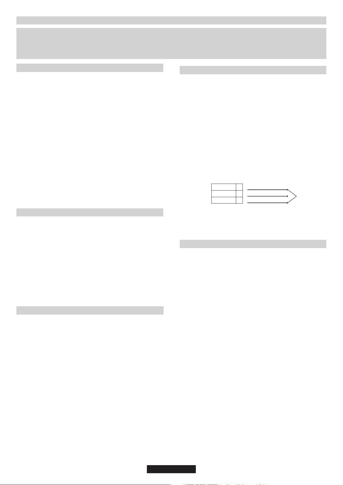
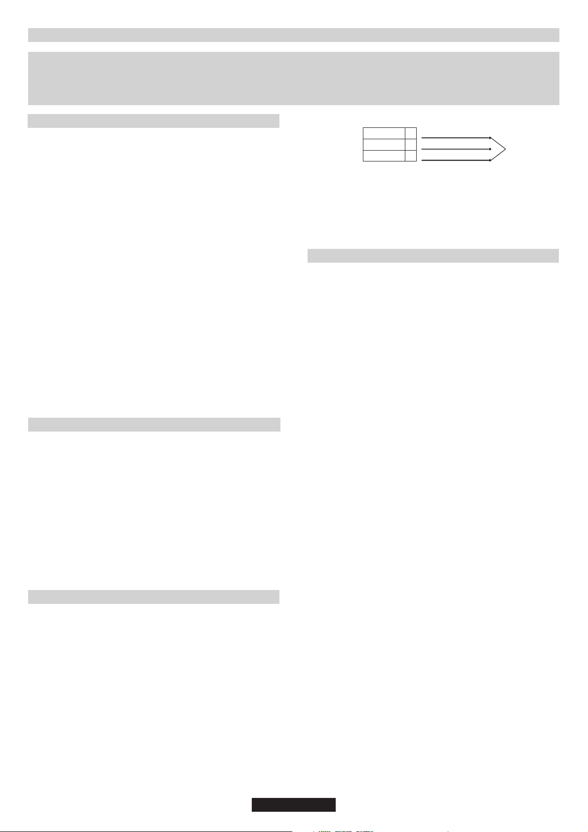
The wiring must be connected to the mains supply as follows:
CONNECT TO SPUR TERMINAL
Green & Yellow Wire Earth Connection
Blue Wire Neutral Connection
Brown Wire Live Connection
Note: We do not advocate the use of earth leakage devices with
electric cooking appliances installed to spur points because of the
«nuisance tripping» which may occur. You are again reminded that the
appliance must be correctly earthed, the manufacturer declines any
responsibility for any event occurring as a result of incorrect electrical
installation.
2.1. ELECTRICAL CONNECTION
Check the data on the rating plate, located on the outside of the unit, to
ensure that thesupply and input voltage are suitable.
Before connection, checkthe earthing system.
By Law, this appliance must beearthed. If this regulation is not complied
with, the Manufacturer will not be responsible for any damage caused to
persons or property. If a plug is not already attached, fit a plug
appropriate to the load indicated on the rating plate. The earth wire is
coloured yellow/green. The plugshould always be accessible.
Where the Hob is connected direct to the electricity supply, a circuit
breaker must befitted.
If the power supply cord is damaged this is to be replaced by a qualified
engineer so asto prevent any potential risk.
The earth wire ( green and yellow coloured ) must be at least 10 mm
longer than thelive and neutral wires.
The section of the cable used must be of the correct size in relation to
the absorbed powerof the hob.
Please check rating plate for the power details and ensure that the
power supply cord is of the type 3x0.75 mm² for 60-75cm
hobs or H05-V2V2-Ffor 75cm hobs.
LIVE
Mains Supply
If an appliance is not fitted with a supply cord and a plug, or with other
means for disconnection from the supply mains having a contact
separation in all poles that provide full disconnection under overvoltage
category III conditions, the instructions shall state that means for
disconnection must be incorporated in the fixed wiring in accordance with
the wiring rules.
EARTH
NEUTRAL
Brown Wire
L
Green/Yellow Wire
Blue Wire
N
H05 GG-F
2.2. GAS CONNECTION
These instructions are for qualified personnel, installation of
equipment must be in line with the relevant national standard. (For
U.K. only: by law the gas installation\commissioning must be
carried out by a "Gas Safe" installer)
All work must be carried out with the electricity supply disconnected.
The rating plate on the hob shows the type of gas with which it is
designed to be used. Connection to the mains gas supply or gas
cylinder should be carried out after having checked that it is regulated
for the type of gas with which it will be supplied. If it is not correctly
regulated see the instructions in the following paragraphs to change
gas setting.
For liquid gas (cylinder gas) use pressure regulators which comply
with the relevant national standards.
Use only pipes,washers and sealing washers which comply with the
relevant national standards.
For some models a conic link is furnished to outfit for the installation in
the countries where this type of link is obligatory; in picture 8 it is
pointed out how to recognize the different types of links (CY =
cylindrical, CO = conic). In every case the cylindrical part of the link
has to be connected to the hob.
When connecting the hob to the gas supply via use offlexible hoses
please ensure that the maximum distance covered by the hose does
not exceed 2 metres.
The flexible tube shall be fitted in such a way that it cannot come into
contact with a moveable part of the housing unit (e.g. a drawer) and does
not pass through any space where it may become crushed/ kinked or
damaged in any way.
To prevent any potential damage to the hob please carry out the
installation following this sequence (picture 6):
1)As illustrated, assemble parts in sequence:
A: 1/2 Male Adaptor Cylindirical
B: 1/2 Seal
C: 1/2 Female Gas Adaptor Conical-Cylindiricalor
Cylindirical-Cylindirical
2)Tighten the joints with the spanner, remembering to twist the
pipes into position.
3)Attach fitting C to mains gas supply using rigid copper pipe or
flexible steel pipe.
03 GB
Power Cable
IMPORTANT: carry out a final check for leaks on the pipe
connections using a soapy solution.
Also, make sure that the flexible pipe cannot come into contact
with a moving part of the cabinet (eg.adrawer) and that it is not
situated where it could be damaged.
Warning: If gas can be smelt in the vicinity of this appliance turn off
the gas supply to the appliance and call the engineer directly. Do not
search for a leak with a naked flame.
NEVER USE A FLAME.
2.3. ADAPTING THE HOB TO DIFFERENT
TYPES OF GAS
To adapt the Hob for use with different types of gas, carry out the
following instructions:
•Remove the grids and burners
•Insert on hexagonal spanner (7 mm) into the burner support
(Figure7)
•Unscrew the injector and replace it with one suitable for the gas to be
used (see gas type table)
2.4. REGULATING THE MINIMUM FLAME
After lighting the burners, turn the control knob to the minimum setting
and then remove the knob (this can easily be removed by applying
gentle pressure).
Using a small «Terminal» type screwdriver the regulating screw can
be adjusted as in Turning the screw clockwise reduces the
gas flow, whilst turning it anticlockwise increases the flow – Use this
adjustment to obtain a flame of approximately 3 to 4 mm in length and
then replace the control knob.
When the gas supply available is LPG - the screw to set the idle flame
must be turned (clockwise) to the end stop.
When you have carried out thenew gas regulation, replacethe old gas
rating plate on your appliance with one (supplied with hob) suitable for
the type of gas for which it has been regulated.
Figure 9.
3. USE OF HOB - USER INSTRUCTIONS
This appliance must only be used for the purpose for which it is
intended, domestic cooking, and any other use will be considered
improper and could therefore be dangerous. The Manufacturer will
not be responsible for any damage or loss resulting from improper
use.
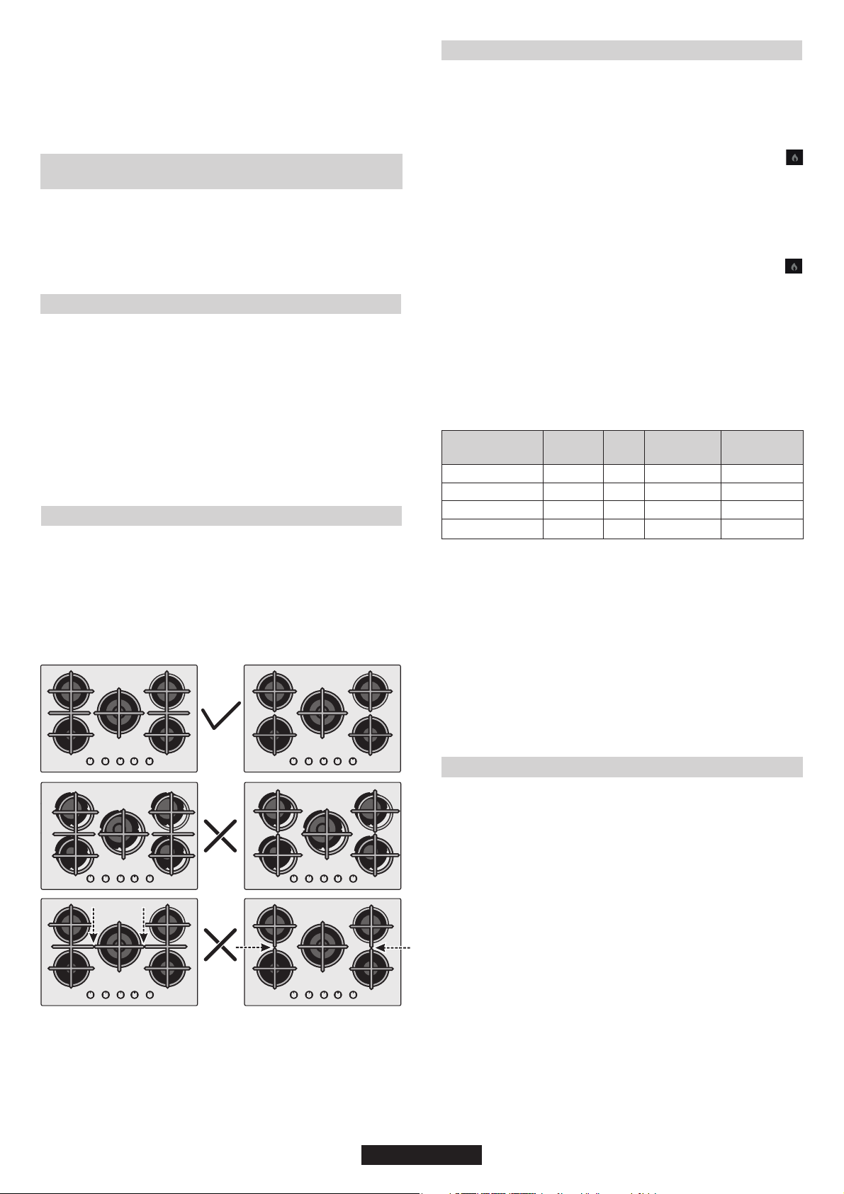
Before using burner, be sure, grid perimeters center the burner as
below figure.
If you are using Cast Iron Grids; underneath the grid, position of it is
stated. Be sure for the exact grid is used in correct position.
3.1. USING THE GAS BURNER
Prior to switching on the gas hob ensure that the burners and burner
caps are correctly placed within their position.
This hob is fitted with electronic ignition to ignite the burner.
To ignite the burnerscarry out the following:
° push in and turn the knob anticlockwise to the larger flame symbol
and keep pushed 5 s after ignition.
The ignition system will continue to generate sparks as long as the
control knob is being pressed
Warning: If there is no electricity on appliance to ignite the burner a
match or a lighter should be used carring out the following:
°place a lighted match or lighter close to the burner
°Push in and turn the knob anticlockwise to the larger flame symbol
and keep pushed 5 s after ignition.
Warning: In any case If after 5 s the burner has not lit, stop operating
the device and wait at least 1 min before attempting a further ignition
of the burner.
GENERALADVISE
For best results, use cooking vessels with a flat surface. The size of
the surface should match the gas burner side as follows. TableA.
Burner Type
AUX
Auxiliary
SR
Semi Rapid
R
Rapid
DC 4 kW MONO
The gas burner should be regulated so that the flame does not overlap
the base of the pan. Vessels with a concave orconvex baseshould not
be used.
WARNING: If a flame is accidentally extinguished, turn the knob
to the off position and do not attempt to re-ignite if for at least 1
minute.
If over the years the gas taps become stiff to turn it is necessary to
lubricate them.
Such operation must be carried out only by qualified Service
Engineers.
Ø pan/pot
(cm)
10 - 18
12 - 22
16 - 26
16 - 26
Power
(kW)
1,00
1,75
2,70
4,00
G20/20 mbar
(methane)
95 l/h
167 l/h
257 l/h
381 l/h
G30/28-30 mbar
(LPG)
73 g/h
127 g/h
196 g/h
291 g/h
Table A
4. MAINTENANCE AND CLEANING
Before cleaning the hob, ensure the appliance has cooled down.
Remove the plug from the socket or (if connected directly) switch off
the electricity supply.
Cleaning and user maintenance shall not be made by children without
supervision
Never use abrasives, corrosive detergents, bleaching agents or
acids. Avoid any acid or alkaline substances (lemon, juice, vinegar
etc.) on the enamelled, varnished or stainless steel sections.
When cleaning the enamelled, varnished or chrome sections, use
warm soapy water or a non caustic detergent. For stainless steel use
an appropriate cleaning solution.
The burners can be cleaned with soapy water. To restore their original
shine, use a household stainless steel cleaner. After cleaning, dry the
burners and replace.
It is important the Burners are replaced correctly.
04 GB

Chromed grids and burners
Chromed grids and burners have a tendency to discolour with use.
This does not jeopardize the functionality of the hob.
Our After Sales Service Centre can provide spare parts if required.
7. DECLARATION OF COMPLIANCE
The appliance complies with European Directive 2009/142/EC (GAD)
and starting from 21/04/2018 with Gas Appliances Regulation
2016/426 (GAR).
5. AFTERCARE
Before calling out a Service Engineer please check the following:
• that the plug is correctly inserted and fused;
• that the gas supply is not faulty.
If the fault cannot be detected:
Switch off the appliance and call the After Service Centre. DO NOT
TAMPER WITH THE APPLIANCE.
6. PROTECTION OF THE ENVIRONMENT
This appliance is labelled in accordance with
European Directive 2012/19/EU regarding electric
and electronic appliances (WEEE). The WEEE
contain both polluting substances (that can have a
negative effect on the environment) and base
elements (that can be reused). It is important that the
WEEE undergo specific treatments to correctly
remove and dispose of the pollutants and recover all
the materials. Individuals can play an important role in ensuring that
the WEEE do not become an environmental problem; it is essential to
follow a few basic rules:
- The WEEE should notbe treated as domestic waste;
- The WEEE should be taken to dedicated collection areas managed
by the town council or a registered company.
In many countries, domestic collections may be available for large
WEEEs. When you buy a new appliance, the old one can be returned
to the vendor whomust acceptit freeof chargeas a one-off, aslong as
the appliance is of an equivalent type and has the same functions as
the purchased appliance.
By placing the mark on the product, we are confirming
compliance to all relevant European safety, health and environmental
requirements which are applicable in legislation for this product.
SAVINGAND RESPECTINGTHE ENVIRONMENT
Where possible use lid to cover the pan. Regulate the flame to not
overlap the diameter of the pan.
Table 1
Burner Plate
Burner
Type
FFD
AUX 1kW
SR 1,75 kW
R 2,7 kW
DC 4 kW MONO
Nominal Heat Input
G20/20 mbar
G30/28-30 mbar
Installation Class
Voltage V/Frequency Hz
Electrical Input Power
Electric Ignition
Product Dimension
4 Gas - L1
AUX/SR/2R
PVUH60MF
YES
1
1
2
-
8,15 kW 9,45 kW
776 l/h
593 g/h
3
220-240V 50/60Hz 220-240V 50/60Hz 220-240V 50/60Hz
1
YES
595x505x42
4 Gas - L2, L4
AUX/SR/R/DC AUX/SR/2R/DC
PVUH60MF
YES
1
1
1
1
900 l/h
688 g/h
3
1
YES
595x505x42
5 Gas - L3
PVUH75MF
12,15 kW
1158 l/h
745x505X42
YES
1
1
2
1
884 g/h
3
1
YES
This appliance has been designed for non-professional, i.e. domestic, use.
05 GB

ISTRUZIONI DI SICUREZZA
Si consiglia di conservare le istruzioni di uso e
montaggio per riferimento successivo e, prima di
montare il piano di cottura, annotare il suo numero
di serie per richiedere assistenza al Servizio postvendita.
AVVERTENZA: l'elettrodomestico e le sue parti
accessibili diventano calde durante l'uso.
Prestare attenzione ad evitare qualsiasi contatto
con le resistenze di riscaldamento. Mantenere
lontani dall'elettrodomestico i bambini di età
inferiore agli 8 anni, a meno che non siano
continuamente supervisionati.
AVVERTENZA: utilizzare unicamente protezioni per
piani di cottura progettate dal produttore della cucina
o indicate dal produttore dell'elettrodomestico nelle
istruzioni d'uso come adatte, o ancora protezioni
incorporate nell'elettrodomestico. L'utilizzo di
protezioni non adatte può provocare incidenti.
AVVERTENZA: la cottura senza sorveglianza su un
piano di cottura in presenza di grasso o olio nella
pentola può essere pericolosa, con rischio di
incendi. NON cercare MAI di spegnere un incendio
con acqua, bensì spegnere l'elettrodomestico e
coprire la fiamma con un coperchio o una coperta
antifiamma.
AVVERTENZA: pericolo di incendio: non
appoggiare nulla sulle superfici di cottura.
AVVERTENZA: se la superficie è crepata, non
toccare la vetroceramica e spegnere
l'elettrodomestico per evitare la possibilità di
elettrocuzioni.
L'elettrodomestico può essere utilizzato da
bambini di età superiore a 8 anni e da persone con
ridotte capacità fisiche, sensoriali o mentali,
oppure prive di esperienza e conoscenza, se
supervisionate o istruite riguardo all'uso
dell'elettrodomestico in sicurezza, e se
comprendono i rischi che derivano dall'uso dello
stesso. I bambini dovrebbero essere supervisionati
per assicurarsi che non giochino con
l'elettrodomestico. La pulizia e la manutenzione da
parte dell'utente non possono essere effettuate da
bambini senza supervisione.
ATTENZIONE: il processo di cottura deve essere
supervisionato. Un processo di cottura di breve
termine deve essere supervisionato in continuo.
Si consiglia vivamente di tenere i bambini a
distanza dalle zone di cottura quando queste
sono in funzione o quandosono spente, per tutto il
tempo durante il quale l'indicatore di calore
residuo rimane attivo, per evitare il rischio di
ustioni gravi.
Questo elettrodomestico non è concepito per
funzionare con temporizzatori esterni o con
sistemi di comando a distanza separati.
Se è presente, non guardare direttamente gli
elementi riscaldati della lampada alogena.
Collegare al cavo di alimentazione una spina
dimensionata per la tensione, la corrente e la
potenza indicate nella targhetta e dotata del
contatto di terra. La presa deve essere
dimensionata per la potenza indicata sulla
targhetta e deve avere il contatto di terra collegato
e funzionante. Il conduttore di terra è giallo-verde.
Questa operazione deve essere eseguita solo da
un tecnico adeguatamente addestrato. In caso di
incompatibilità tra presa e spina
dell'elettrodomestico, richiedere ad un tecnico
specializzato di sostituire la presa con un'altra di
tipo compatibile. La spina e la presa devono
essere conformi alle normative attuali del paese
di installazione.
Il collegamento alla rete di alimentazione può
essere effettuato anche collocando un interruttore
automatico onnipolare tra l'elettrodomestico e la
rete di alimentazione, in grado di supportare il
carico massimo collegato, in linea con la
legislazione corrente.
Il cavo di terra giallo-verde non deve essere
interrotto dall'interruttore automatico. La presa o
l'interruttore automatico onnipolare utilizzati per il
collegamento devono essere facilmente accessibili
al momento del montaggio dell'elettrodomestico.
La disconnessione può essere eseguita con la
spina accessibile o aggiungendo un interruttore
sul cablaggio fisso, nel rispetto delle normative
relative ai cablaggi.
Se il cavo di alimentazione dell'elettrodomestico
dovesse essere danneggiato, farlo sostituire dal
produttore, dal suo servizio tecnico o da tecnici
qualificati, per evitare rischi. Il conduttore di terra
(giallo-verde) deve essere più lungo di 10 mm sul
lato della morsettiera. La sezione dei conduttori
interni deve essere adatta alla potenza assorbita
dal piano di cottura (come indicato sulla
targhetta). Il cavo di alimentazione deve essere di
tipo H05 GG-F per pancottura da 60-75 cm o
H05-V2V2-F per pancottura da 75 cm.
Non appoggiare sul piano di cottura oggetti
metallici come coltelli, forchette, cucchiai o
coperchi. Potrebbero scaldarsi eccessivamente.
Non appoggiare sulle zone riscaldanti pellicole di
alluminio e padelle in plastica.
Dopo ogni utilizzo è necessario pulire il piano di
cottura per evitare l'accumulo di sporcizia e grasso.
Se ci sono accumuli di questo tipo vengono cotti
nuovamente quando il piano di cottura viene
acceso, creando fumo e odori sgradevoli per non
parlare del rischio di propagazione di incendi.
Non utilizzare mai un getto di vapore o ad alta
pressione per la pulizia dell'elettrodomestico.
Non toccare le zone riscaldanti durante il
funzionamento o per un breve periodo dopo l'uso.
Non cuocere mai gli alimenti direttamente sul
piano di cottura in vetroceramica.
Utilizzare sempre i recipienti di cottura adatti.
Mettere sempre la pentola al centro del gruppo sul
quale si sta effettuando la cottura. Non appoggiare
nulla sul pannello di comando.
Mai utilizzare il piano di cottura come superficie di
lavoro.
Mai utilizzare il piano di cottura come tagliere.
Non appoggiare oggetti pesanti al di sopra del
piano di cottura. Se cadono sul piano possono
danneggiarlo.
Non utilizzare il piano di cottura per riporvi oggetti.
Non fare scivolare i recipienti sul piano di cottura.
Il funzonamento dell'elettrodomestco alle frequenze
nomnal non rchede alcuna operazone o
mpostazone.
In caso drottura del vetro del pano cottura:
Spegnere mmedatamente tuttbrucatore le
resstenze elettrche e staccare l'almentazone
elettrca dell'elettrodomestco.
Non toccare la superfce dell'elettrodomestco.
Non utlzzare l'elettrodomestco.
06 IT
1. ISTRUZIONI PER L'INSTALLATORE
INSTALLARE UN ELETTRODOMESTICO PUÒ ESSERE UN'OPERAZIONE COMPLICATA CHE, SE NON ESEGUITA CORRETTAMENTE, PUÒ
COMPROMETTERE SERIAMENTE LA SICUREZZA DELL'UTENTE. È PER QUESTA RAGIONE CHE L'OPERAZIONE DEV'ESSERE CONDOTTA
DA PERSONALE PROFESSIONALMENTE QUALIFICATO CHE TENGA PRESENTE LE NORME VIGENTI. NEL CASO IN CUI QUESTO AVVISO
VENGA IGNORATO E L'INSTALLAZIONE VENGA ESEGUITA DA PERSONALE NON QUALIFICATO, IL PRODUTTORE DECLINA OGNI
RESPONSABILITÀ PER OGNIPROBLEMA TECNICO DEL PRODOTTO SIAIN CASODI DANNIA COSE O PERSONE SIA INASSENZA DI ESSI.
1.1 INSTALLAZIONE.
Il plano cotturapuò essereInstallato In qualsiasi top che sia resistente
ad una temperatura di 100°C e abbia uno spessore di 25-45 mm. La
dimensione del vano di Inserimento del plano cottura è mostrata In
Figura 2.
Qualora sotto II plano cottura vi sia un vano accessibile bisogna
predisporre un parete di divisione In materiale Isolante (legno o slmili)
(Figura 3).
Qualora II plano venga Incassato In modo che sul suo lato sinistro o
destro ci sia una parete, la distanza non dev'essere Inferiore a 117 cm
(60 cm) o 25 cm (75 cm) (vedere Figura 2); mentre la distanza tra la
parete posteriore e II plano deve essere di almeno .70 mm
La distanza tra II plano cottura e qualsiasi altro apparecchio sopra di
esso (es. una cappa) non deve essere Inferiore a 70 cm .(Figura 4)
Alimentazione
principale
Il mezzo di disconnessione deve essere incorporato nel cablaggio
fisso in accordo con le leggi di cablaggio.
Per il collegamento diretto alla rete, è necessario prevedere un
dispositivo che assicuri la disconnessione dalla rete, con una
distanza di apertura dei contatti che consenta la disconnessione
completa nelle condizioni della categoria di sovratensione III,
conformemente alle regole di installazione.
FASE
TERRA
NEUTRA
Cavo Marrone
F
Cavo Verde/Giallo
Cavo Blu
N
Cavo di
alimentazione
2.2 CONNESSIONE GAS.
Oggetti metallici nel cassetto possono raggiungere temperature
elevate a seguito del ricircolo dell'aria. Pertanto si consiglia di
utilizzare una separazione intermedia in legno.
Importante - Il diagramma In figura 1 mostra come deve essere
applicato il sigillante.
Il piano cottura è fissato grazie a morsetti di supporto agganciati alla
base.
Se sopra un forno è montato un piano cottura di 60 cm, si consiglia di
creare delle aperture all'interno dei mobili per garantire la corretta
circolazione dell'aria.
La dimensione di queste aperture deve essere di almeno 300 cm e
posizionate come in .
Quando un piano cottura da 75 cm viene posizionato sopra un
forno, la parte posteriore deve essere raffreddata ad aria.
Figura 5
60 cm o
²
1.2 LOCAZIONI CONSIGLIATE.
Questo apparecchio può essere installato in accordo con il
regolamento vigente e solo in un ambiente ben ventilato. Leggere le
istruzzioni prima dell'installazione o l'uso dell'apparecchio.
Un piano gas produce umidità e calore nell'area in cui è installato. Per
questa ragione bisogna garantire una buona ventilazione sia tramite
passaggio di aria naturale sia grazie all'installazione di una cappa
d'aspirazione. Un uso intensivo e prolungato dell'apparecchio
richiede una ventilazione maggiore, come l'apertura di una finestra o
aumentando la velocità di ventole di raffreddamento, se possibile. Se
non vi èla possibilità di installare una cappa, un aspiratore può essere
installato su una parete esterna o su una finestra affinché ci siano
delle correnti d'aria nell'area.
Una ventola elettrica è in grado di assicurare un cambio d'aria
completo nella cucina 3-5 volte ogni ora. L'installatore dovrà seguire
gli standard nazionali pertinenti.
2.1 CONNESSIONE ELETTRICA.
Controllare i dati sulla placca segnaletica, situata sotto l'unità, per
assicurarsi che il collegamento elettrico sia corretto. Prima della
connessione, controllare l'impianto di messa a terra. Per legge,
quest'apparecchio deve avere la messa a terra. Se questa
operazione non viene eseguita, il produttore non sarà responsabile di
eventuali danni occorsi a persone o proprietà. Se non è già applicata
una spina, applicarne una appropriata come indicato sulla placca
segnaletica. Il cavo di messa a terra è di color verde/giallo. La spina
deve essere posizionata in modo tale che sia sempre accessibile.
Qualora il piano cottura sia connesso direttamente all'alimentazione
principale, bisognerà predisporre anche un salvavita. Se il cavo di
alimentazione è danneggiato dovrà essere sostituito da personale
qualificato in modo da prevenire qualsiasi potenziale rischio.
Il cavo di messa a terra (di color verde/giallo) deve essere più lungo di
almeno 10 mm rispetto ai cavi neutro e fase. La sezione del cavo
usato deve essere delle giuste dimensioni in base all'assorbimento
dell'apparecchio.
Si prega di controllare laplacca segnaleticaper idettagli riguardanti la
potenza dell'aparecchio e assicurare che il cavo di connessione sia
dei tipi 3x0.75 mm² H05 GG-F per piani cottura da 60-75 cm o H05V2V2-F per piani cottura da 75 cm.
Queste istruzioni sono per personale qualificato, l'installazione
dell'apparecchio deve seguire le direttive standard nazionali. (Solo
per U.K.: perlegge l'installazione deve essere commissionata ad
un operatore "Corgi")
Qualsiasi operazione deve essere svolta staccando la corrente
elettrica.
La placca segnaletica sotto il piano cottura mostra il tipo di gascon cui
bisogna allacciare l'apparecchio. La connessione all'alimentazione
gas principale deve essere apportata dopo aver controllato che sia
regolata in base al tipo di gas previsto dall'apparecchio. Se non è
regolata correttamente guardare le istruzioni nei paragrafi seguenti
per cambiare le impostazioni gas.
Per il gas liquido GPL usare dei regolatori di pressione che siano
conformi con gli standard nazionali.
Usare solo tubazioni, guarnizioni e sigillanti che siano conformi con gli
standard nazionali.
Per alcuni modelli viene fornito in dotazione una raccordo conico,
come attrezzatura per l'installazione, neipaesi dove èobbligatorio per
legge; in Figura 8 viene mostrato come riconoscere i diversi tipi di
raccordi (CY=cilindrico, CO=conico). In qualsiasi caso la parte
cilindrica del raccordo sarà connessa al piano cottura.
Quando la connessione del piano all'alimentazione gas verrà
effettuata utilizzando manicotti flessibili assicurarsi che la distanza
massima coperta dal tubo non superi i 2 metri.
Il tubo flessibile deve essere sistemato in modo tale che non possa
entrare in contatto con parti mobile dell'unità abitativa (ad esempio un
cassetto) e non passi attraverso alcuno spazio che sia suscettibile a
congestionamento.
Per prevenire qualsiasi danno al piano seguire l'installazione
seguendo questa sequenza :(Figura 6)
1) Come illustrato, assemblare le parti in sequenza:
A: 1/2Adattatore cilindricomaschio
B: ½ Sigillante
C: 1/2Adattatore gasfemmina conico-cilindrico o cilindrico-cilindrico
2) Stringere le giunture con la chiave inglese, ricordando di
mettere le tubature in posizione.
3) Attaccare l'elemento C all'alimentazione gas usando tubi di
rame o manicotti flessibili in acciaio.
IMPORTANTE: eseguire un ultimo controllo con una soluzione a
base disapone per controllare che le tubature non perdano. Non
usare mai una fiamma. Inoltre assicurarsi che il manicotto
flessibile non venga acontatto conuna partemobile dellacucina
(es. cassetto) e che non sia situato dove possa essere
danneggiato.
Attenzione: se si avverte odore di gas in vicinanza dell'apparecchio
spegnere l'alimentazione e chiamare il tecnico. Non cercare
un'eventuale perdita con una fiamma.
07 IT

2.3 ADATTARE IL PIANO COTTURA CON.
DIVERSI TIPI DI GAS
Per adattare il piano cottura all'uso di diversi tipi di gas, seguire le
seguenti istruzioni:
• rimuovere le griglie e i bruciatori
• inserire una chiave esagonale a tubo (7 mm) dentro il supporto
bruciatore ( )Figura 7
• svitare l'iniettore e sostituirlo con uno compatibile con il tipo di gas
che verrà utilizzato (vedere la tabella tipi di gas).
2. REGOLARE IL MINIMO DELLA FIAMMA4.
Dopo aver acceso i bruciatori, girare la manopola del gas sul minimo
quindi rimuovere la manopola (può esere rimossa con una leggera
pressione).
L'apparecchio può essere usato da bambini dagli 8 anni in su e
persone con ridotte capacità fisiche, sensoriali o mentali o senza
esperienza e conoscenzadel prodotto se supervisionate o dando loro
istruzioni riguardo al funzionamento dell'apparecchio in maniera
sicura e coscente del rischio possibile.
Usare una piccola estermità come un cacciavite per regolare la vite
come mostrato in Figura 9. Girando la vite in senso orario si riduce il
flusso di gas,viceversa in senso antiorario si aumenta il flusso - Usate
questi aggiustamenti per ottenere una fiamma approssimativamente
di 3/4 mm di lunghezza dopodiché riposizionare la manopola. Nel
caso in cui l'alimentazione sia di tipo GPL - la vite per regolare la
fiamma ideale deve essere ruotata (in senso orario) verso fine corsa.
Una volta che si è impostata la nuova regolazione, sostituire la
vecchia placca segnaletica sull'apparecchio con una adatta al tipo di
alimentazione gas che è stata installata.
3. USO DEL PIANO - ISTRUZIONI UTENTE
Quest'apparecchio deve essere utilizzato solo per gli scopi con cui è
stato pensato, qualsiasi altro utilizzo può essere considerato
improprio e quindi pericoloso. Il produttore non è responsabile per
qualsiasi danno o perdita dovuti ad un uso inappropriato.
Questo apparecchio non è pensato per essere usato da persone
(inclusi bambini) con handicap fisici, sensoriali o capacità mentali
limitate, con mancanza di esperienza e conoscenza, a meno che non
siano supervisionati o istruiti all'uso dell'apparecchio da una persona
responsabile della loro incolumità.
I bambini devono essere supervisionati per assicurare che non
giochino con l'apparecchio.
3. USO DEL BRUCIATORE GAS1.
Prima di accendere il piano di cottura a gas, accertarsi che i bruciatori
e i relativi cappellotti siano posizionati correttamente.
Questo piano di cottura è dotato di accensione elettronica per
accendere il bruciatore.
Per accendere i bruciatori, procedere come segue:
° premere all'interno e ruotare in senso antiorario la manopola verso il
simbolo della fiamma più alta e tenere premuto per 5 secondi
dopo l'accensione.
Il sistema di accensione continua a generare delle scintille per tutto il
tempo in cui la manopola viene premuta
Avvertenza: Se non c'è elettricità nell'elettrodomestico per accendere
il bruciatore utilizzare un fiammifero o un accendisigari, procedendo
come segue:
° mettere un fiammifero acceso o un accendisigari vicino al bruciatore
° premere all'interno e ruotare in senso antiorario la manopola verso il
simbolo della fiamma più alta e tenere premuto per 5 secondi
dopo l'accensione.
Avvertenza: In ogni caso, se il bruciatore non si accende dopo 5
secondi, smettere di azionare l'accensione e attendere almeno un
minuto prima del successivo tentativo di accensione.
AVVISIGENERICI:
Per risultati migliori, la dimensione delle pentole deve seguire la
dimensione del bruciatore come mostrato qui a seguito. TabellaA.
Tipo di bruciatore
AUX
Ausiliario
SR
Semi rapido
R
Rapido
DC 4 kW MONO
Ø / (cm)
10 - 18
12 - 22
16 - 26
16 - 26
Potenza
(kW)
1,00
1,75
2,70
4,00
Per contenitori più piccoli il bruciatore gas può essere regolato in
modo che la fiamma non superi la pase della pentola. Recipienti con
una base concava o convessa non possono essere usati.
ATTENZIONE: se un bruciatore si spegne accidentalemente,
riportare la monopola sulla posizione spenta e non tentare di
riaccenderlo prima che sia passato 1 minuto.
Se col passare del tempo il rubinetto del gas si indurisce è necessario
lubrificarlo.
Questo tipo di operazione deve essere eseguita da personale
qualificato.
G20/20 mbar
(Metano)
95 l/h
167 l/h
257 l/h
381 l/h
G30/28-30 mbar
(LPG)
73 g/h
127 g/h
196 g/h
291 g/h
Tabella A
4. MANUTENZIONE E PULIZIA
Prima di pulire il piano cottura, assicurarsi che l'apparecchio si sia
raffreddato.
La pulizia e la manutenzione non dovrebbero essere fatte da bambini
senza supervisione.
Rimuovere la spina dalla presa corrente o (se connessa direttamente
all'alimentazione generale) toglierela corrente dall'impianto generale.
Non usare sostanze abrasive, detergenti corrosivi, agenti sbiancanti o
acidi. Evitare ogni tipo di acido o sostanza alcalina (limone, aceto, etc.)
per pulire leparti smaltate, laccate o in acciao inox.
Quando bisogna pulire le parti smaltate, laccate o cromate, usare acqua
calda con sapone o un detergente non corrosivo. Per l'acciaio
antimacchia usare unasoluzione appropriata.
I bruciatori possono essere puliti con acqua e sapone. Per ripristinare la
loro brillantezza originale, usare un comune prodotto di pulizia per
superfici in acciaio.Dopo averli puliti, asciugarli e ricollocarli al loro posto.
È importante chei bruciatorivengano riposizionaticorrettamente.
Griglie cromate ebruciatori
Le griglie cromateeibruciatoritendono a diventare scuri con l'uso.
Questo è un fenomeno normale ed inevitabile, che tuttavia non
compromette assolutamente il buon funzionamento del piano cottura. In
ogni caso sono disponibili, presso i centri servizio post vendita, i pezzi di
ricambio.
08 IT

5. RIPRISTINO
Prima di contattare un tecnico del Centro Assistenza si prega di
controllare:
• he la spina sia ben inserita e collegata;C
• he l'alimetazione gas non sia difettosa.C
Se il malfunzionamento non è identificabile:
spegnere l'apparecchio - non manometterlo e chiamare il Centro
Assistenza.
-
6. RISPETTO DELL'AMBIENTE
Questo apparecchio è contrassegnato in conformità alla
Direttiva europea 2012/19/EU sulle apparecchiature
elettriche ed elettroniche (WEEE). I WEEE contengono
sia sostanze inquinanti (che possono provocare
conseguenze negative sull’ambiente) che componenti
di base (che possono essere riutilizzati). E’ importante
rimuovere e smaltire correttamente tutti gli inquinanti e recuperare
tutti i materiali. I singoli possono giocare un ruolo importante
nell’assicurare che i WEEE non diventino un problema ambientale; è
essenziale seguire alcune regole di base:
- i WEEE non devono essere trattati come rifiuti domestici;
- i WEEE devono essere portati ai punti di raccolta appositi gestiti dal
comune o da società registrate.
In molti paesi, per i WEEE di grandi dimensioni, potrebbe essere
presente la raccolta domestica. Quando si acquista un nuovo
apparecchio, quello vecchio potrebbe essere restituito al rivenditore
che deve acquisirlo gratuitamente su base singola, sempre che
l’apparecchio sia del tipo equivalente e abbia le stesse funzioni di
quello acquistato.
che i WEEE siano soggetti a trattamenti specifici per
7. DICHIARAZIONE DI CONFORMITÀ
L'elettrodomestico è conforme alla Direttiva Europea 2009/142/CE
(GAD) e a partire dal 21/04/2018 con il regolamento GAR (Gas
Appliances Regulation) 2016/426.
Apponendo la marcatura su questo prodotto, dichiariamo, sotto
la nostra responsabilità, di ottemperare a tutti i requisiti relativi alla
tutela di sicurezza, salute e ambiente previsti dalla legislazione
europea in essere per questo prodotto.
8. GARANZIE
Il prodotto è garantto, oltre che asensdlegge, alle condzonene
termnrportatsul certfcato dgaranza convenzonale nserto nel
prodotto. Il certfcato dovrà essere conservato e mostrato al nostro
Centro dAssstenza Tecnca Autorzzato, n caso dnecesstà,
nseme allo scontrno comprovante l’acqusto dell’elettrodomestco.
Puoconsultare le condzondgaranza anche sul nostro sto
nternet.
Per ottenere assstenza compla l’apposto form on-lne oppure
contattacal numero che trovndcato nella pagna dassstenza del
nostro sto nternet.
SALVARE ERISPETTAREL'AMBIENTE
Ove possibile, utilizzare il coperchio per coprire la padella. Regolare
la fiamma per non superare il diametro della padella.
Tabella 1
Piastra del bruciatore
Bruciatore
Genere
FFD
Aux 1kW
Sr 1,75 kW
R 2,7 kW
Dc 4 kW MONO
Ingresso nominale di calore
G20/20 mbar
G30/28-30 mbar
Classe di installazione
Voltaggio / Frequenza (V / Hz)
Potenza elettrica in ingresso
Iniezione elettrica
Dimensione prodotto (mm)
4 Gas - L1 4 Gas - L2, L4 5 Gas - L3
AUX/SR/2R
PVUH60MF
sì
1
1
2
-
8,15 kW 9,45 kW
776 l/h
593 g/h
3
220-240V 50/60Hz 220-240V 50/60Hz 220-240V 50/60Hz
1
sì
595x505x42
AUX/SR/R/DC AUX/SR/2R/DC
PVUH60MF
sì
1
1
1
1
900 l/h
688 g/h
3
1
sì
595x505x42
PVUH75MF
12,15 kW
1158 l/h
884 g/h
745x505X42
sì
1
1
2
1
3
1
sì
Questo apparecchio è stato progettato per uso domestico e non professionale.
09 IT

C
AB
60
560 mm
480 mm
min 70 mm
min 600 mm
min 50 mm
min 170 mm (60 cm)
min 250 mm (75 cm)
75
25 - 45 mm
min. 5 mm
Figure 3
min. 10 mm
42
mm
Figure 1
min.
50 mm
min.
50 mm
25 - 45 mm
min. 5 mm
Min. 70 cm
min. 10 mm
42
mm
Figure 2
min.
50 mm
min.
50 mm
1/2 GAS
CONICAL
CYLINDRICAL
CYLINDRICAL
CONICAL
Figure 8
10
Figure 6
Figure 4
INJECTOR
Figure 7

SR
R R
AUX
GAS TYPEHOBS
SR R
DC
4kW
MONO
L1 L2
AUX
AUX
DC
4kW
MONO
RR
SR
DC
4kW
MONO
AUX
L3
R
SR
L4
DC 4 kW
Mono
G20/G25 20/25mbar 2E+
G30/G31 28-30/37mbar 3+
G20 20mbar 2H
G30/G31 50/50mbar 3B/P
PVUH60MF - DIAMOND (L1)
SINGLE BURNER EFFICENCY
AUX SR R
-
60%
54.3% 54.3%
145H3
G20 20mbar 2H
G30/G31 28-30/37mbar 3+
II2HS3B/PII2EK3B/P
G20 20mbar 2E
G25.3 25mbar 2K
G30/G31 30/30mbar 3B/P
G20 20mbar 2H
G25.1 25mbar 2S
G30/G31 30/30mbar 3B/P
Efficiency Decleration 2016/426
PVUH60MF - BIG FRONT (L2)
SINGLE BURNER EFFICENCY
R
AUX SR R DC
60%
-
54.3% 57.6%
AUX SR R DC
-
G20 20mbar 2H
G30/G31 30/30mbar 3B/P
G20 20mbar 2E
G30/G31 37/37mbar 3B/P
PVUH75MF - CENTRAL (L3)
SINGLE BURNER EFFICENCY
R
60%
54.3% 54.3%
G20 20mbar 2E
G30/G31 50/50mbar 3B/P
57.6%
MEDIUM %56.2
MEDIUM %57.3
PVUH60MF - BIG REAR (L4)
SINGLE BURNER EFFICENCY
AUX SR R DC
60%
-
54.3% 57.6%
MEDIUM %57.3
11
MEDIUM %56.6

GB - IE
The manufacturer will not be responsible for any inaccuracy resulting from printing or transcript errors contained in this brochure. We reserve the right
to carry out modifications to products as required, including the interests of con sumption, without prejudice to the characteri stics relating to safety or
function.
IT
La Ditta costruttrice declina ogni responsabilità per eventualierrori distampa contenuti nel presente libretto. Si riserva inoltre il dirittodi apportare le modifiche
che si renderanno utili aipropri prodotti senza compromettere le caratteristiche essenziali.
RU
42833992 • 70 gr - A4 • 06.2020 • Rev_D
 Loading...